¶ A1 mini (Excluding the Toolhead)
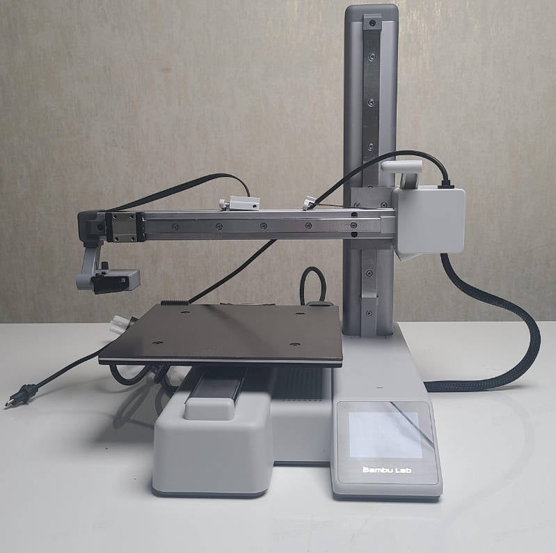
This article provides guidelines and precautions for disassembling and assembling the A1 mini, and the disassembly and assembly of replaceable components involved in this process can also be referenced in this article.
¶ Parts List
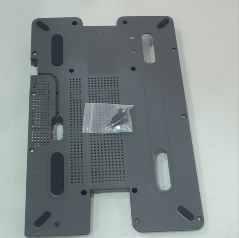
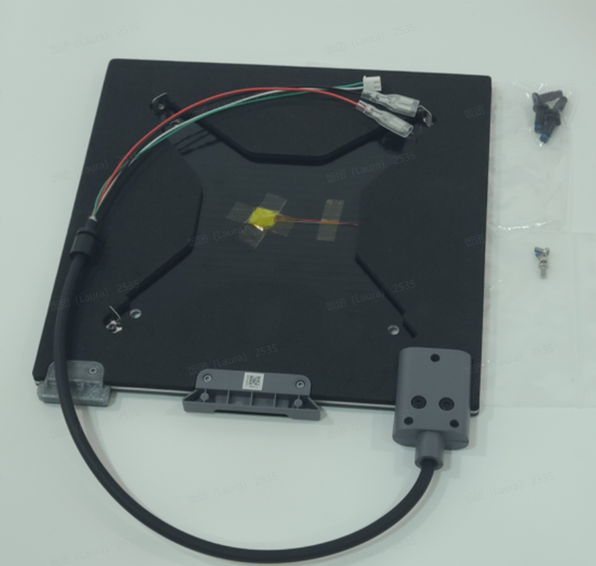
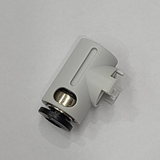
The following are the after-sales spare parts that will be covered in this guideline.
| No. | Name | Image | No. | Name | Image | No. | Name | Image |
| 1 |
A1 Mini Baseplate
|
 |
2 |
Heatbed
|
 |
3 |
PTFE Tube Connector
|
 |
| 4 |
Bambu USB-C Cable
|
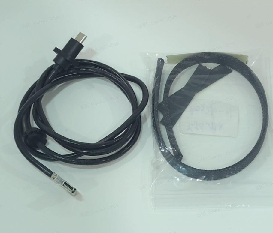 |
5 | X Motor Cover |
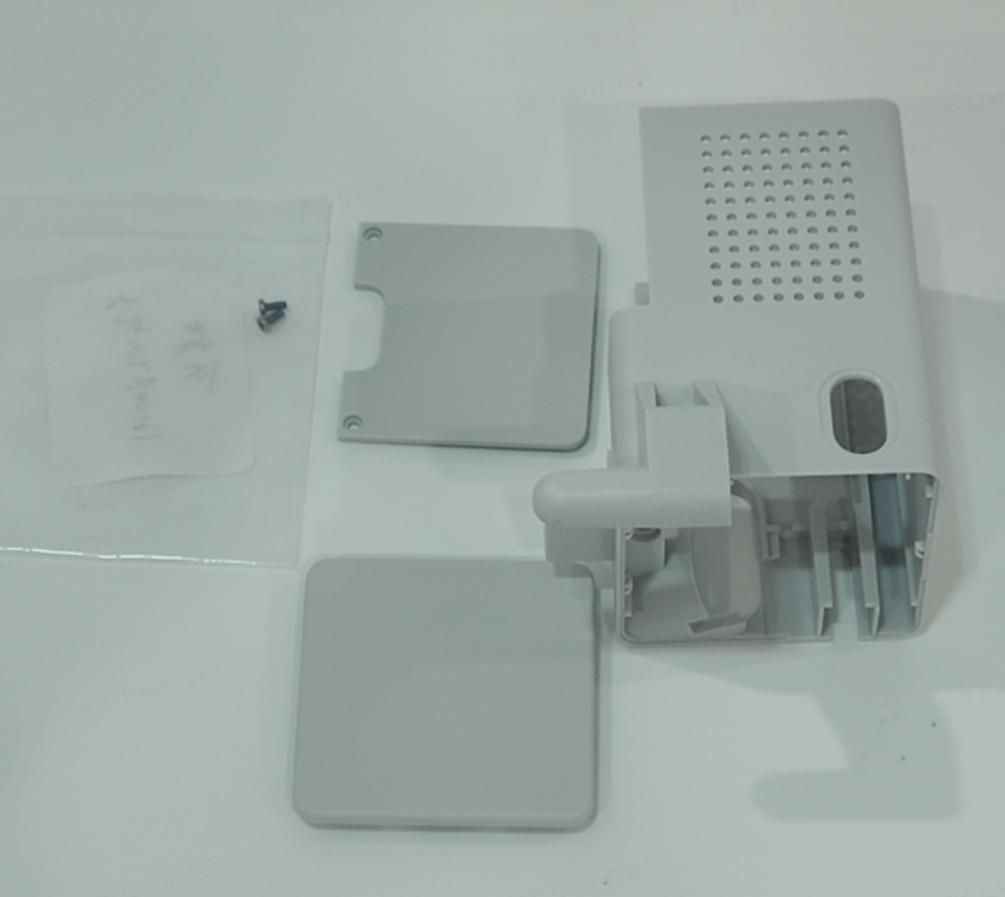 |
6 |
Live View Camera
|
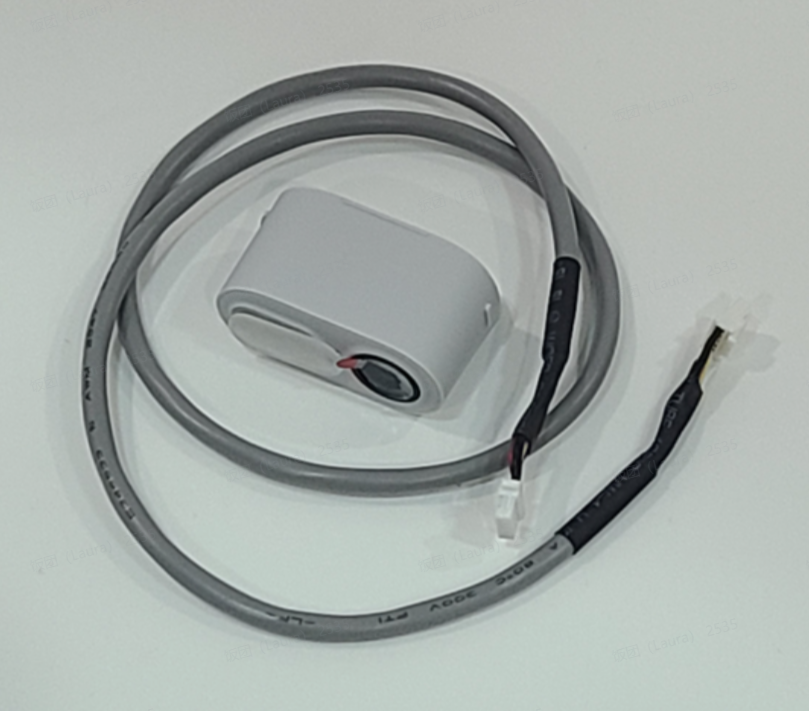 |
| 7 | X Motor |
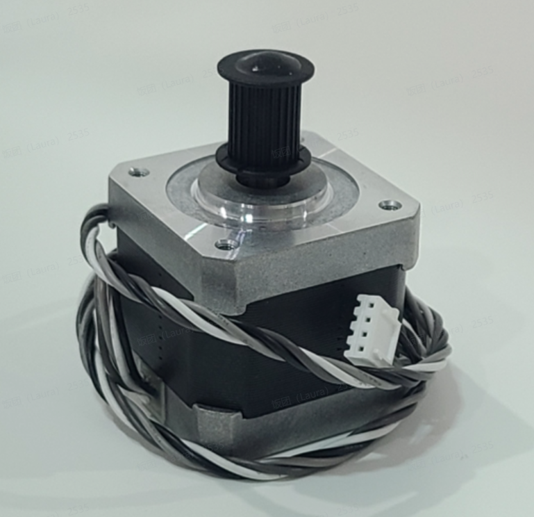 |
8 | Y-axis Linear Rail |
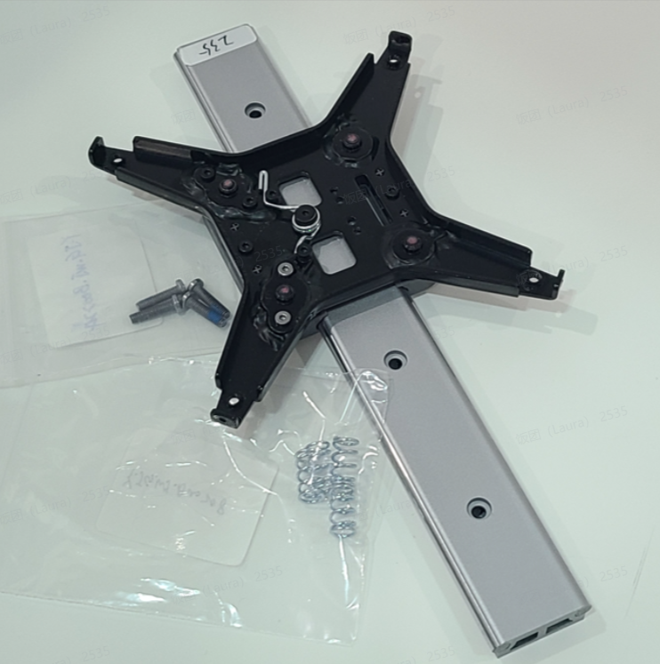 |
¶ Module List
Components that require continued disassembly but are not dealt with in this article.
| No. | Name | Image | No. | Name | Image |
| 1 | X Assembly |
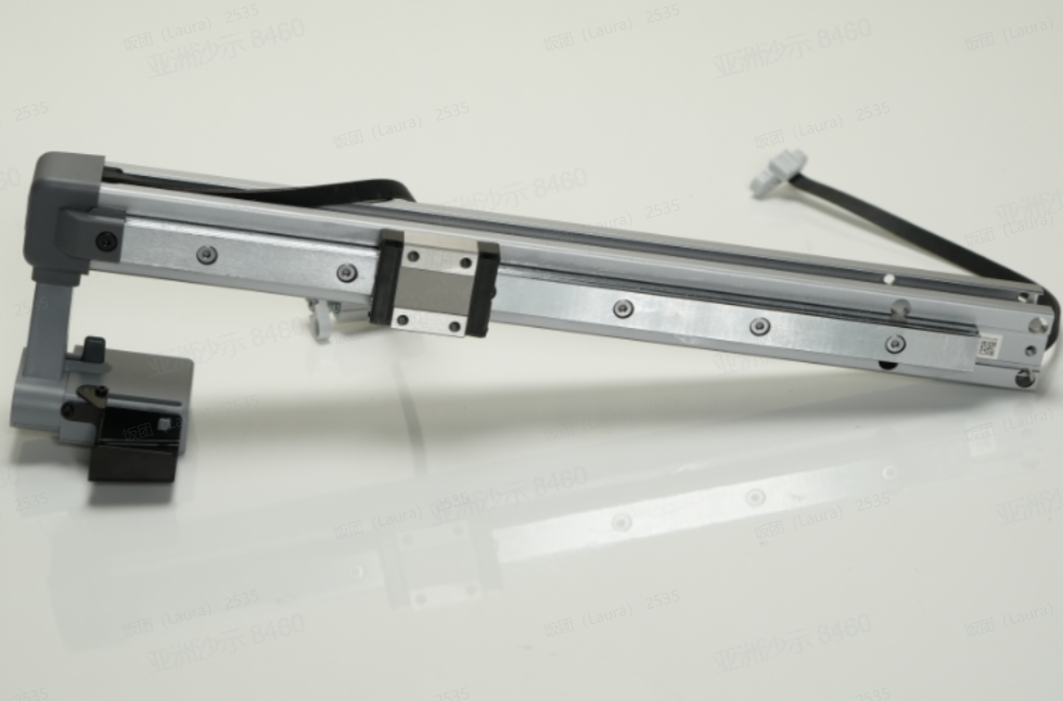 |
2 | Bottom Base Assembly |
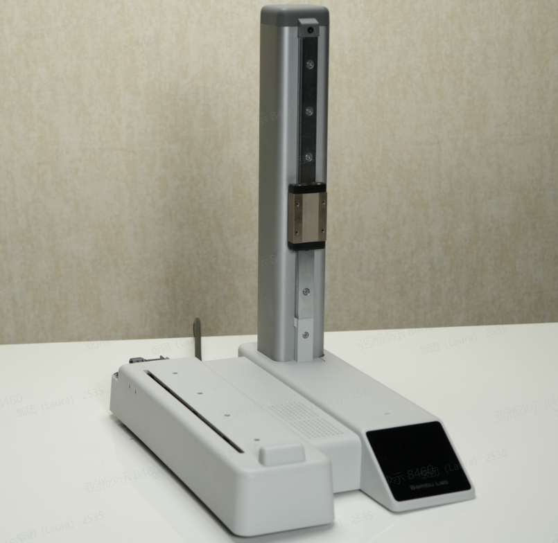 |
¶ Screw List
| Model | Position | Drawings | Model | Position | Drawings | ||
| Screw A |
BT2.6*8 B0046 |
Cable buckles (2PCS+2PCS) |
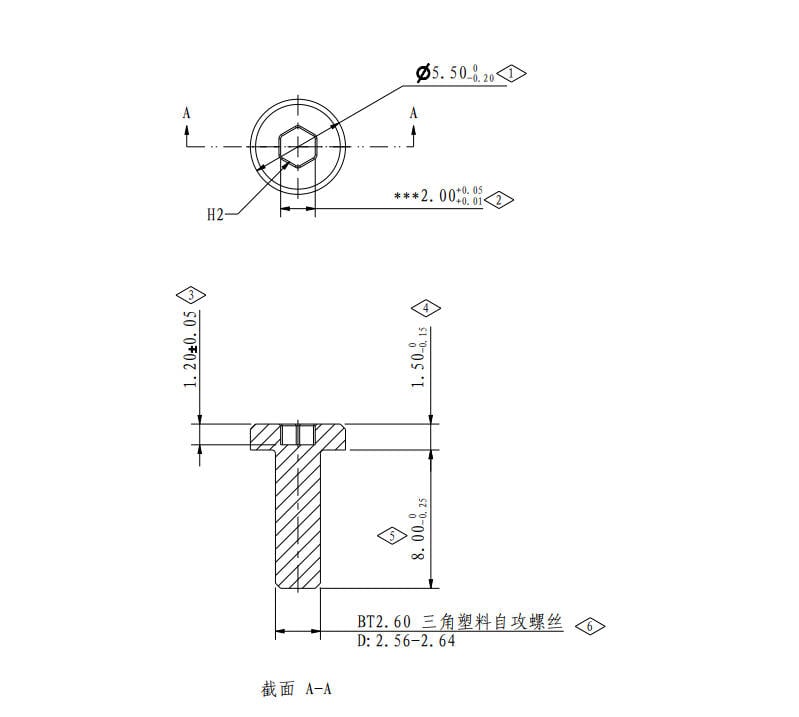 |
Screw B |
BT3*8 B0022
|
Baseplate, Fireproof cover (14PCS+3PCS) |
 |
| Screw C |
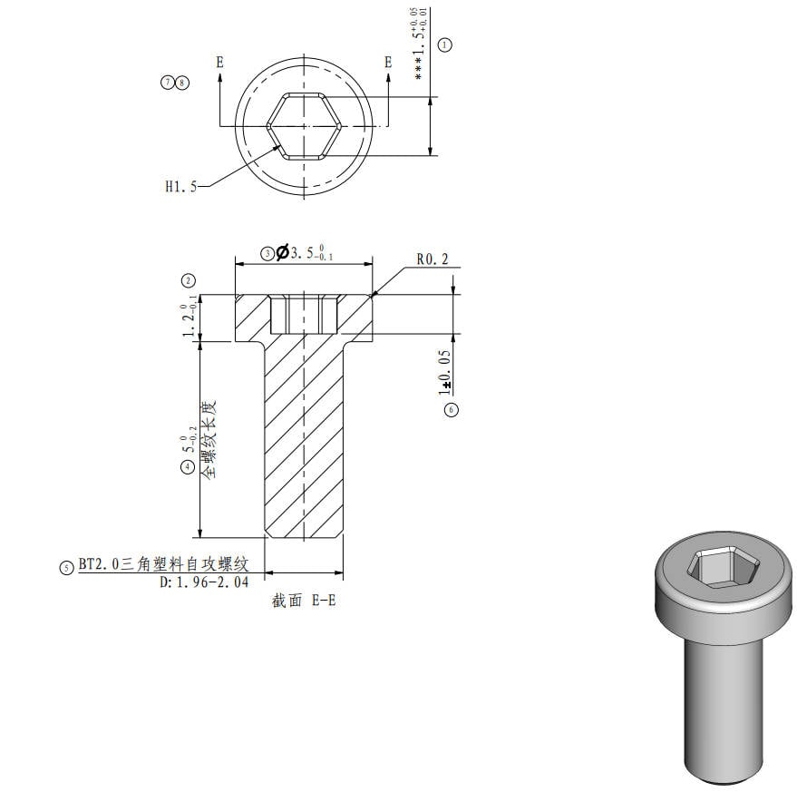
BT2*5 B0017 |
USB plate (2PCS) |
 |
Screw D |
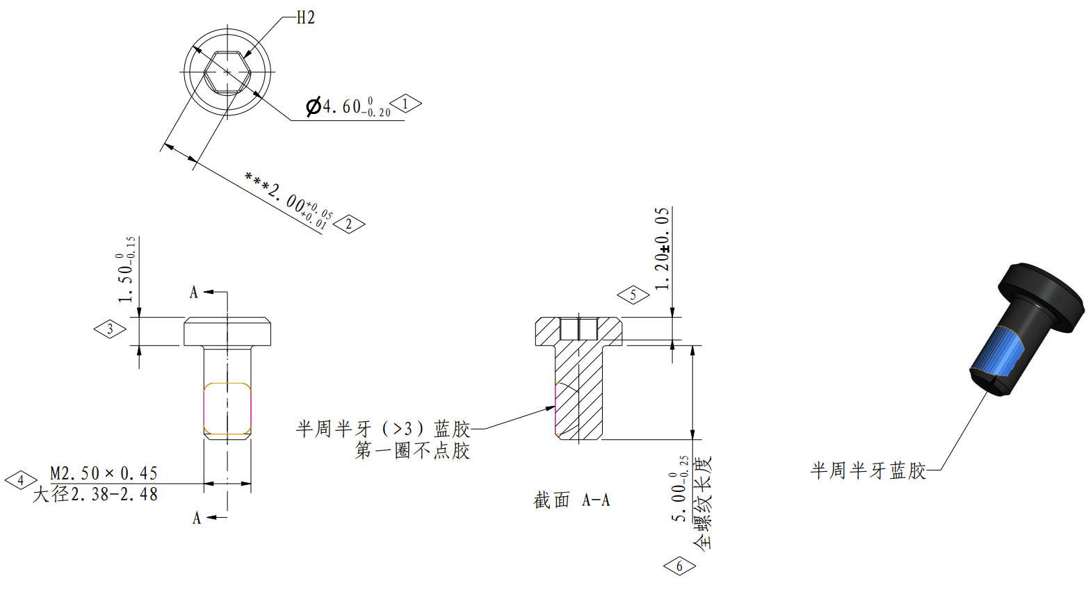
M2.5*5 B0055 |
Heatbed Lock (3PCS) |
 |
| Screw E |
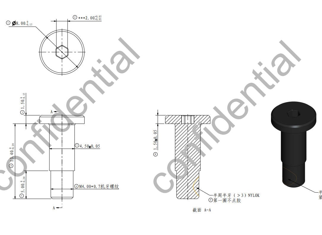
MG4*13 B00229 |
Heatbed Leveling (4PCS) |
|
Screw F |
M3*10 B00208
|
X motor Cover (1PCS) |
 |
| Screw G |
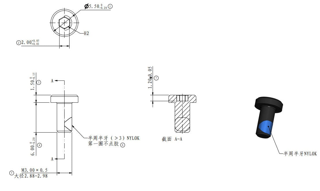
M3*6 B0036 |
X motor Cover (2PCS)
|
 |
Screw H |
M2*4.5 B00211 |
X motor rear cover (2PCS)
|
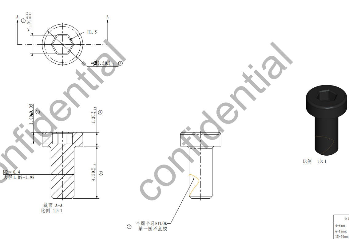 |
| Screw I |
B0010 M3*5 |
X motor (4PCS)
|
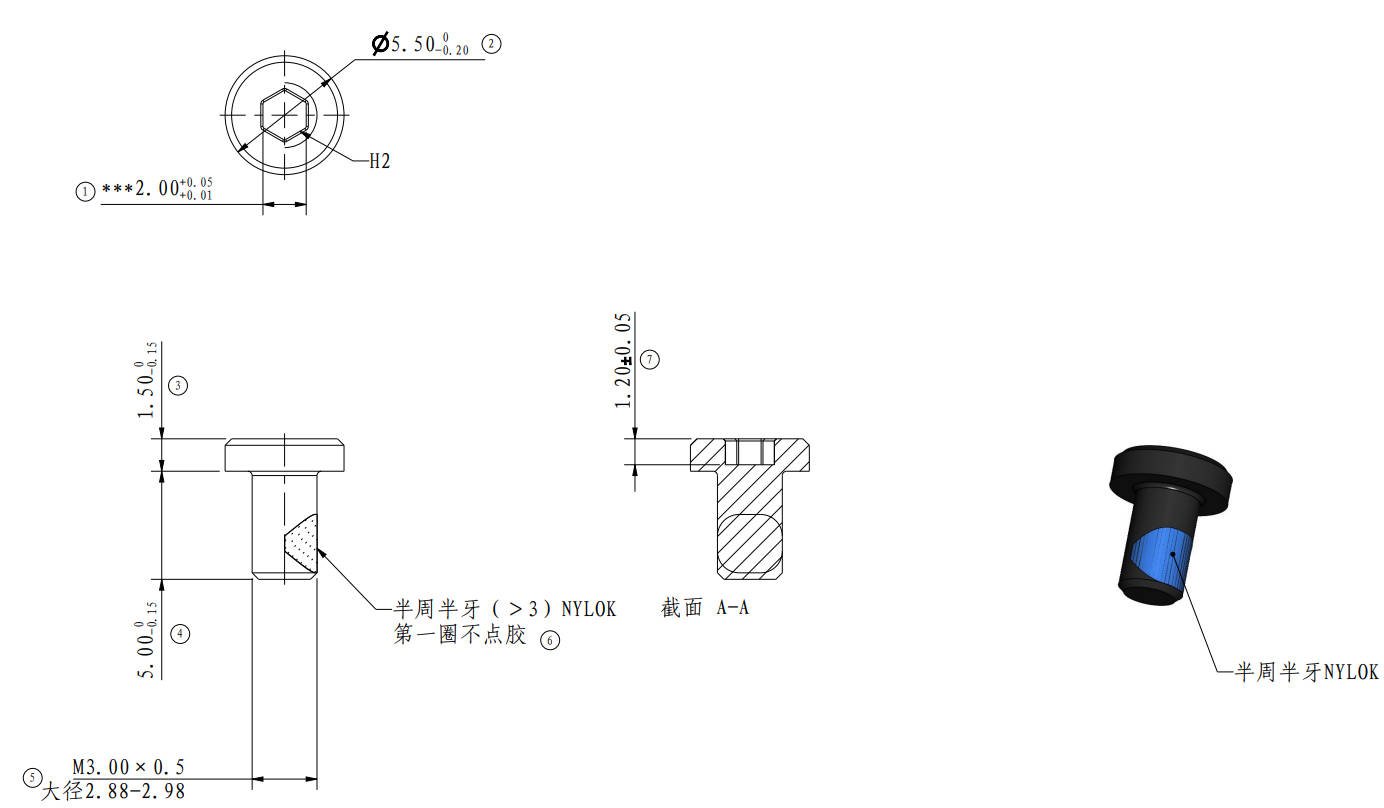
|
Screw J |
M3*6 B00247 |
X-axis (4PCS)
|
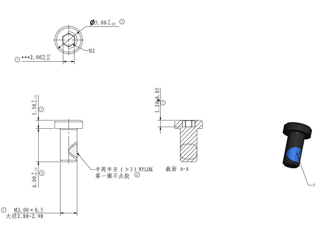 |
| Screw K |
MG3*14 B00212 |
Adapter Bracket (Rear, 2PCS)
|
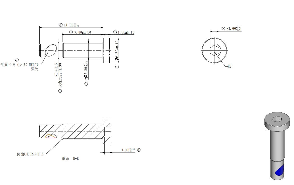 |
Screw L |
B0042 M3*4.5 |
Connecting Plate (2PCS) |
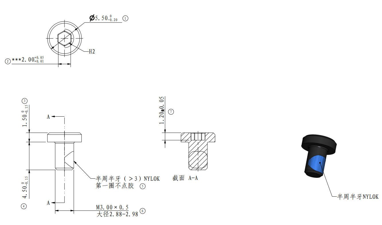 |
| Screw M |
M2.5*18 B00228 |
Y rear cover (2PCS) |
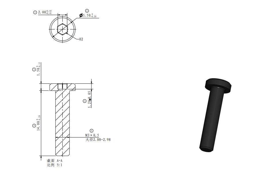 |
Screw N |
M4*16 B00224 |
Y-axis Linear Rail (4PCS) |
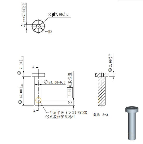 |
¶ Tool List
- H2.0/H1.5 Allen Key
- Wire Cutters
- Needle-nose Pliers
¶ Safety Warning
Important Reminder!
Before performing any maintenance work on the printer and its electronic devices (including Tool head cable), please turn off the printer's power and disconnect the power supply to avoid circuit short-circuits that may cause additional damage to electronic devices and potential safety hazards.
When conducting maintenance or troubleshooting on the printer, please first ensure that the hotend and heated bed are at a safe temperature. Avoid operating them at high temperatures. If it is necessary to perform tasks at high temperatures, please wear appropriate heat-resistant gloves to ensure safe and effective maintenance work
If you have any questions about this guide, please Click here to submit a service ticket, and we will respond promptly and provide the assistance you need.
¶ Video Guide
Due to differences in product versions, there may be some differences in details.
¶ Disassembly Guide
¶ Step 1: Remove the Baseplate
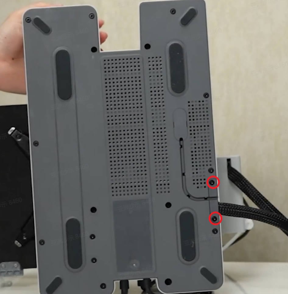
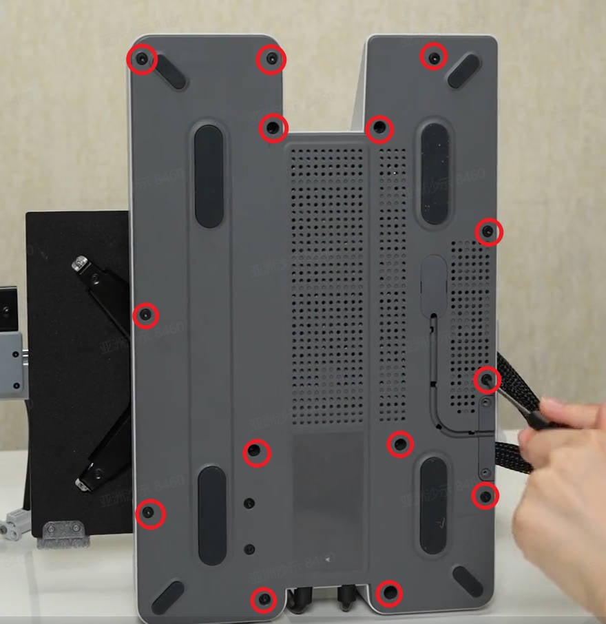
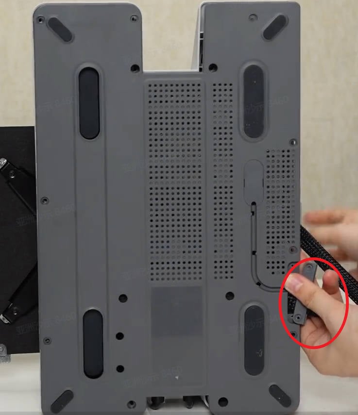
Tilt the printer backward and remove 2 screws A. Remove the cable buckle.
Remove 14 screws B, then pull and stretch the nylon ties to loosen the baseplate and then remove it.
 |
 |
 |
¶ Step 2: Disconnect the cables
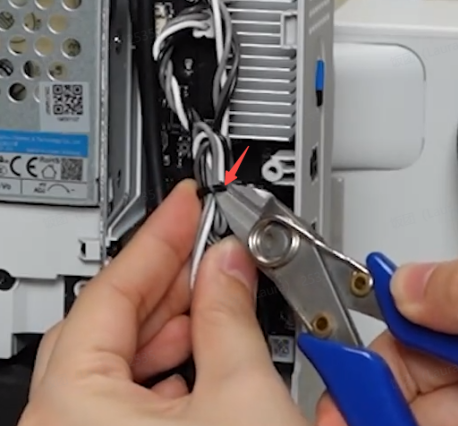
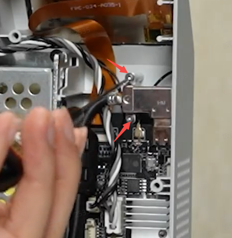
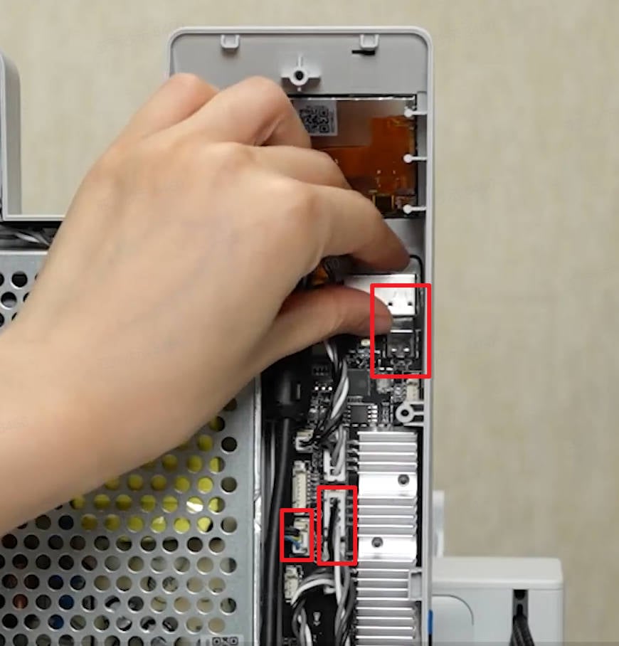
Use wire cutters to cut the zip ties, remove 2 screws C and plate, and disconnect the USB cable, camera cable, and X motor cable from the mainboard.
 |
 |
 |
¶ Step 3:Remove the Heatbed
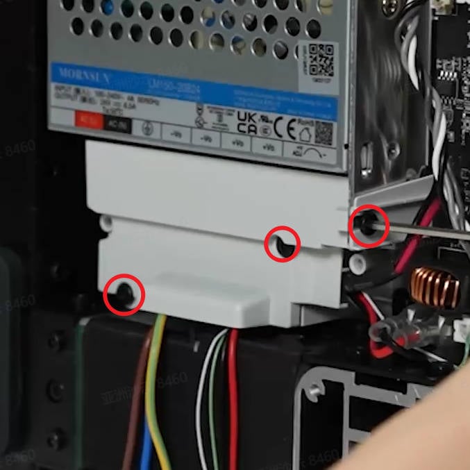
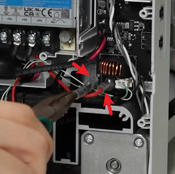
Use an H2.0 hex wrench to remove 3 screws B, remove the fireproof cover, use pliers to remove the two terminal insulating rubber sleeves,
 |
 |
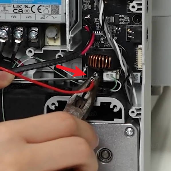
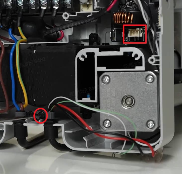
Use a wrench to unlock the plug and unplug the 2 heatbed power cords at the same time; Disconnect the connection of the heatbed signal cable from the mainboard, remove 1 screw A, and loosen the heatbed cable from the cable buckle.
 |
 |
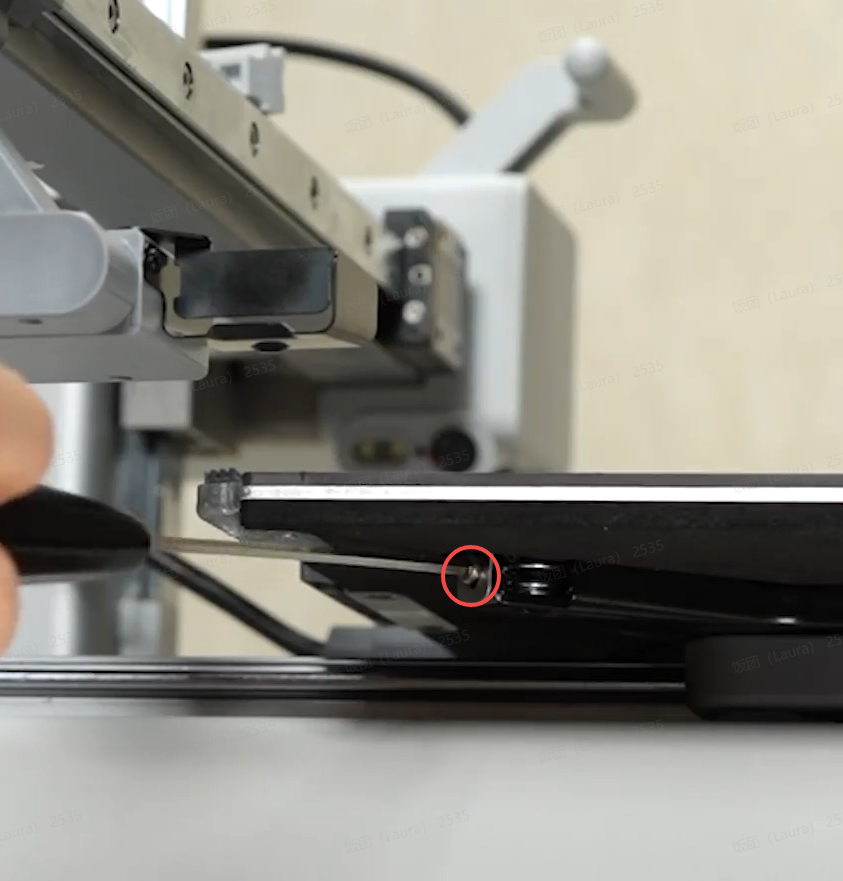
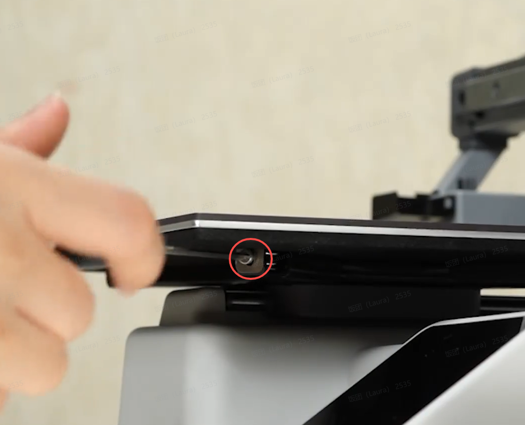
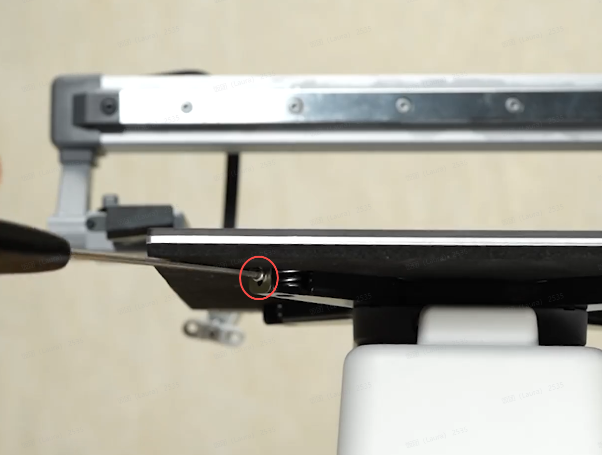
Place the printer upright and remove 3 screws D that secure the heat bed.
 |
 |
 |
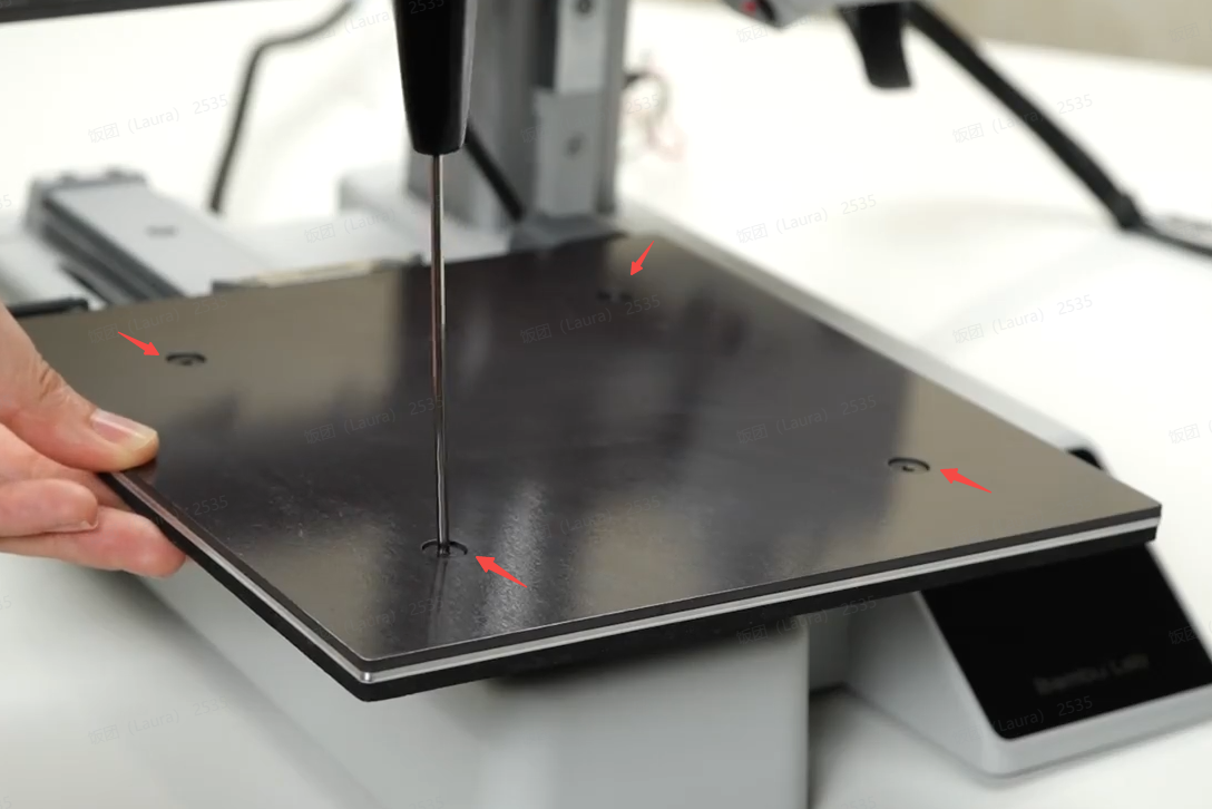
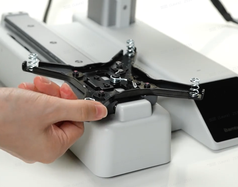
Press down on the heat bed with your hand and remove 4 leveling screws E. Take off the heat bed along with the adjustment springs.
 |
 |
¶ Step 4: Remove the USB cable, camera, and X motor cover
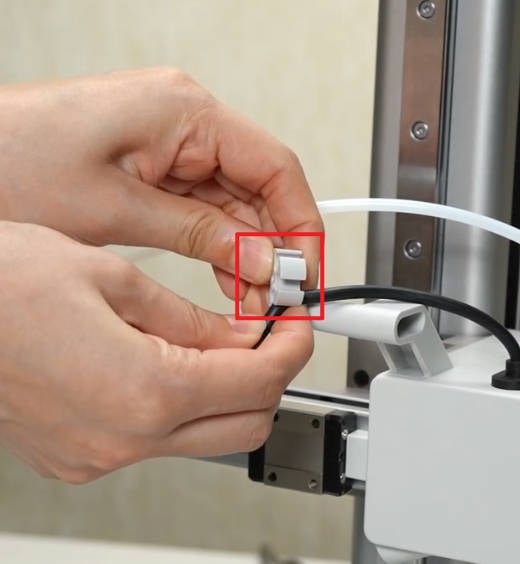
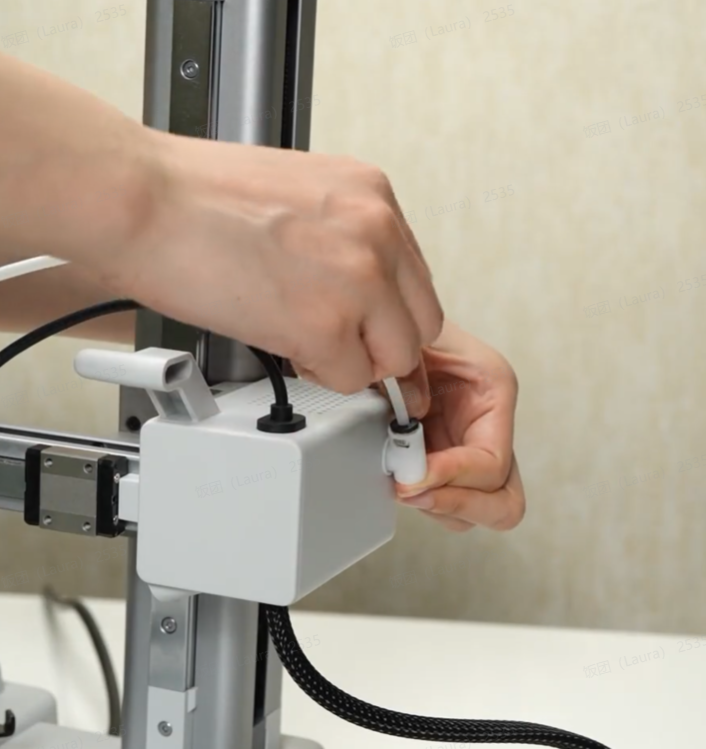
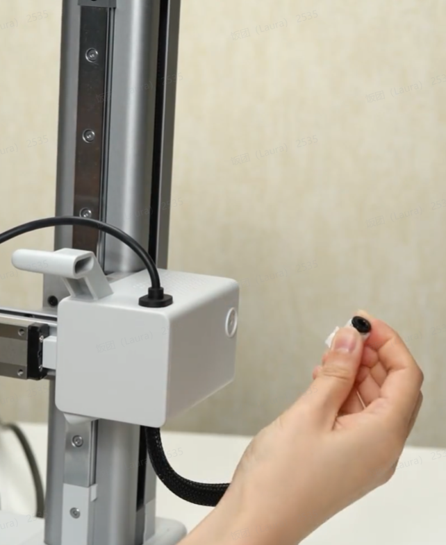
Remove the PTFE tube and USB cable from the Cable Organizer. Press the connector to disconnect the tube, and then remove the PTFE Tube Connector.
 |
 |
 |
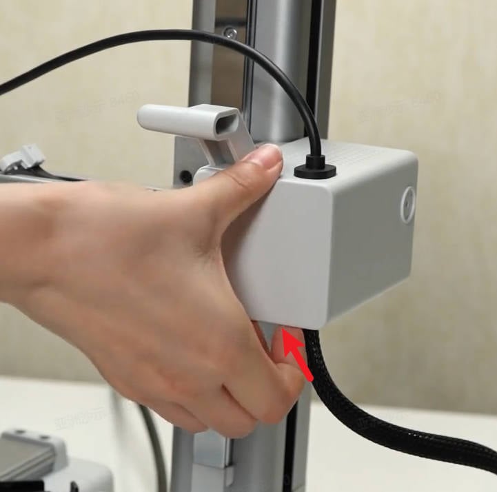
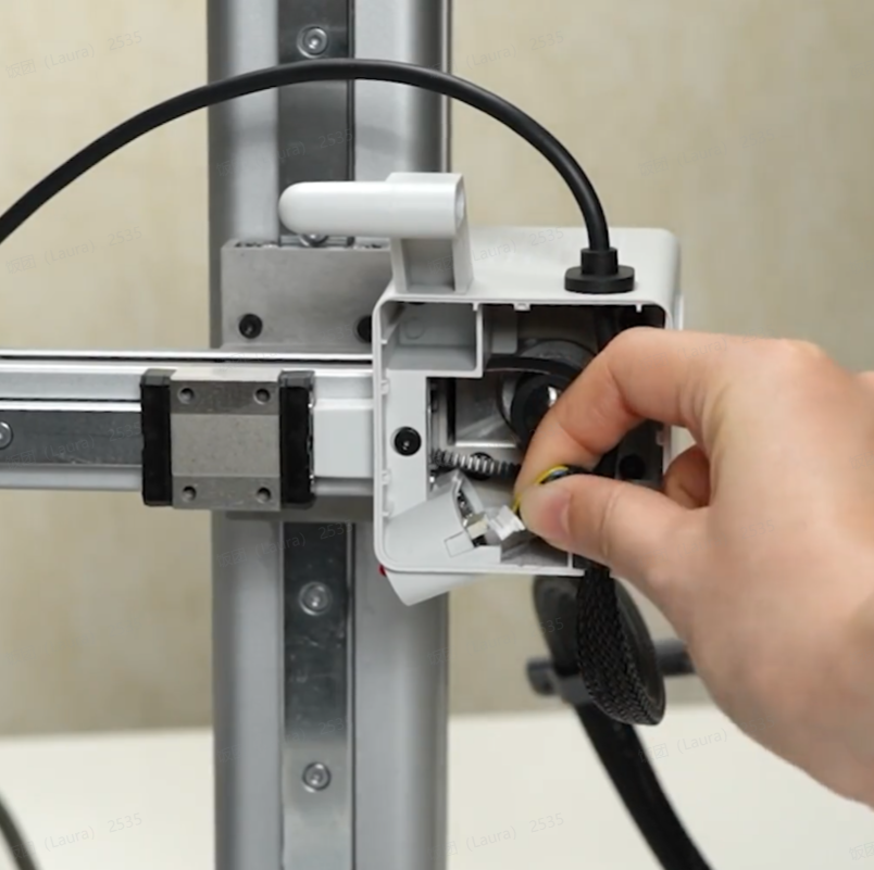
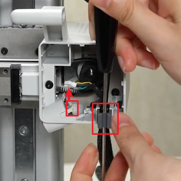
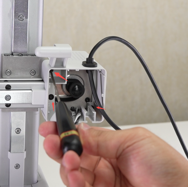
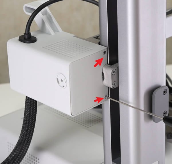
Apply force from below the motor cover front lid to remove it. Disconnect the camera cable. Insert an Allen wrench through the cable clamp and pry it out. Remove the cable clamp.
 |
 |
 |
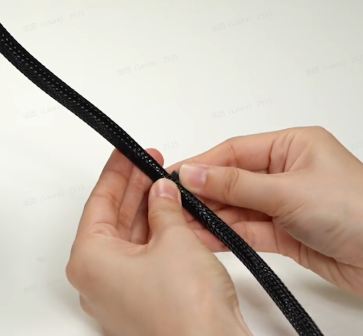
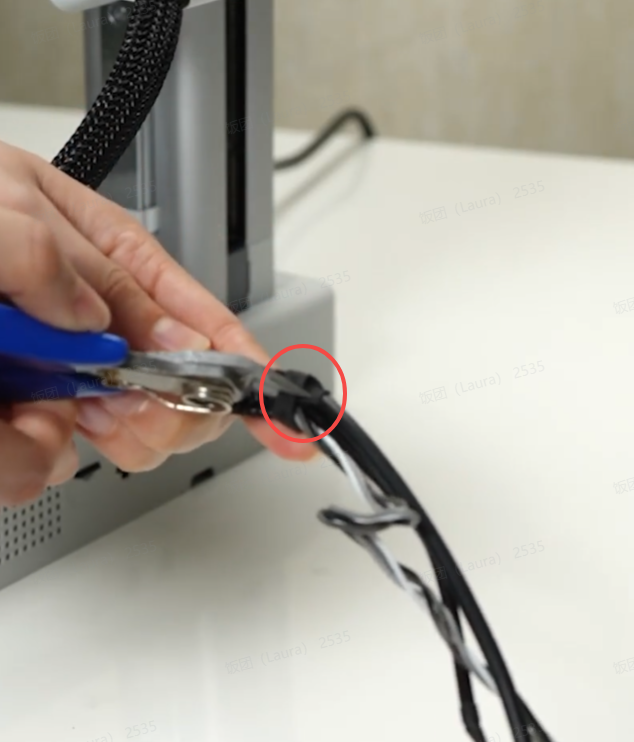
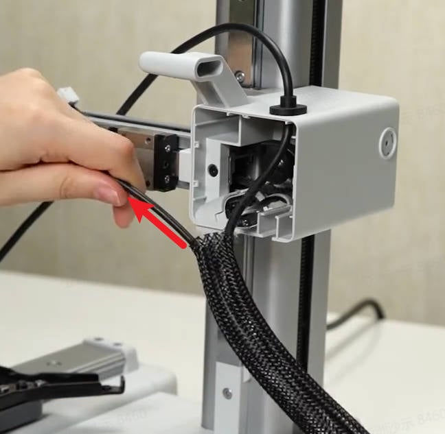
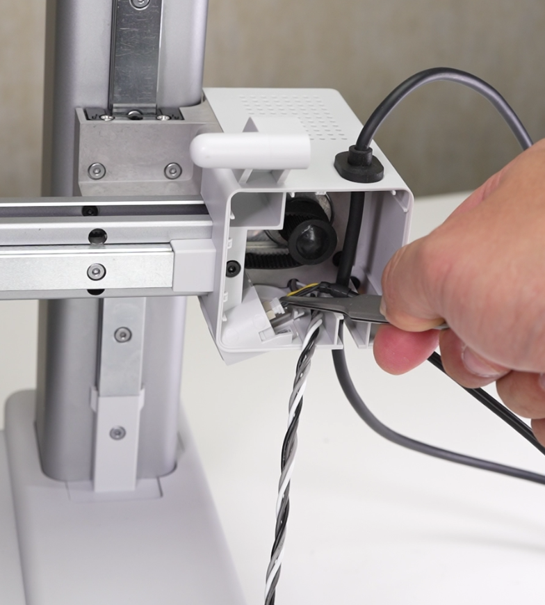
Remove the cable buckle left on the cables, tear off the tape at one end of the nylon mesh, and pull out the camera connection cable and X motor cable;
 |
 |
 |
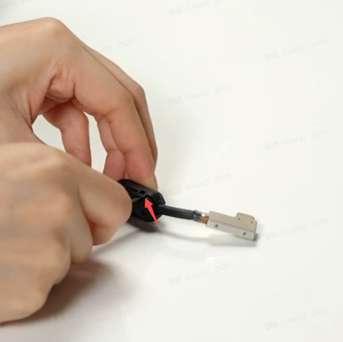
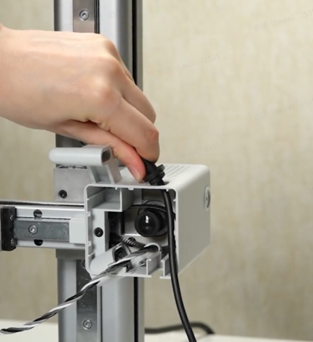
Remove the ferrite cores, pull out the rubber plug on the USB cable from the motor cover, and remove the USB cable;
There are two versions of the USB-C ferrite cores: the split/separated structure shown in the image and an integrated one-piece ferrite core.
If it is the integrated one-piece structure, you do not need to install the separated/split type of ferrite core onto the cable, as the ferrite core is already integrated into the cable.
The two versions are shipped randomly. The final product received should be considered the authoritative version.
 |
 |
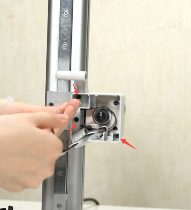
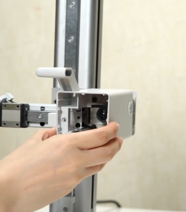
Remove 1 screw F, 2 screws G, and take off the X motor cover assembly;
 |
 |
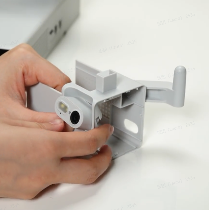
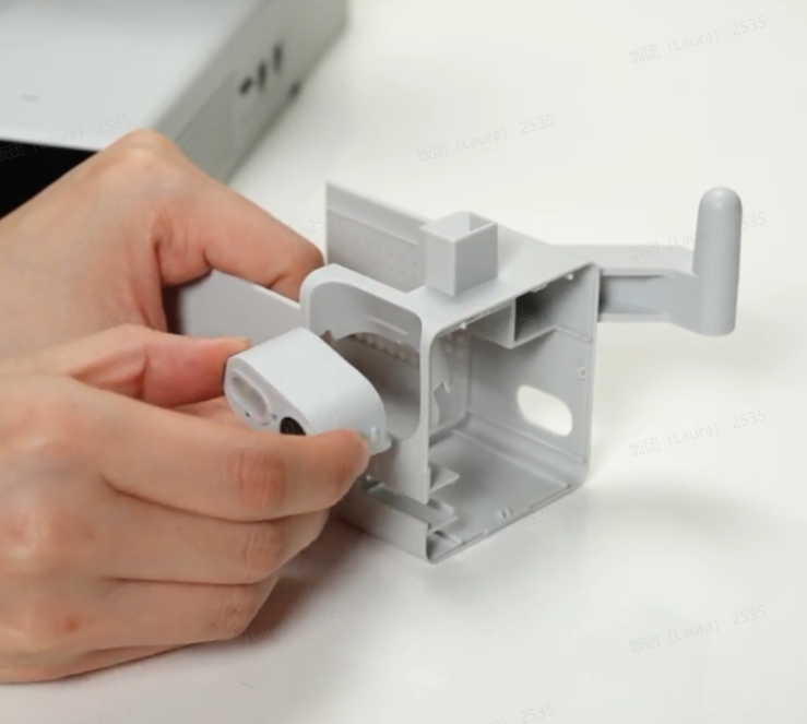
Press the direction of the arrow to unlock the camera and remove the camera from the X motor cover.
 |
 |
 |
¶ Step 5: Remove the X Motor
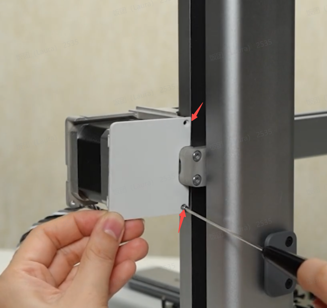
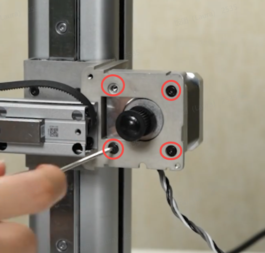
Remove 2 screws F and remove the motor rear cover. Remove 4 screws I and take down the X motor
 |
 |
¶ Step 6: Remove the X-axis assembly.
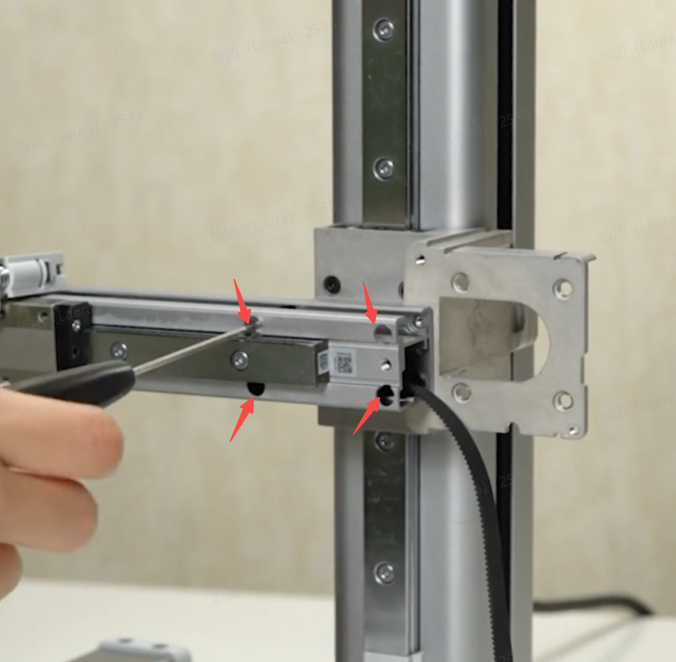
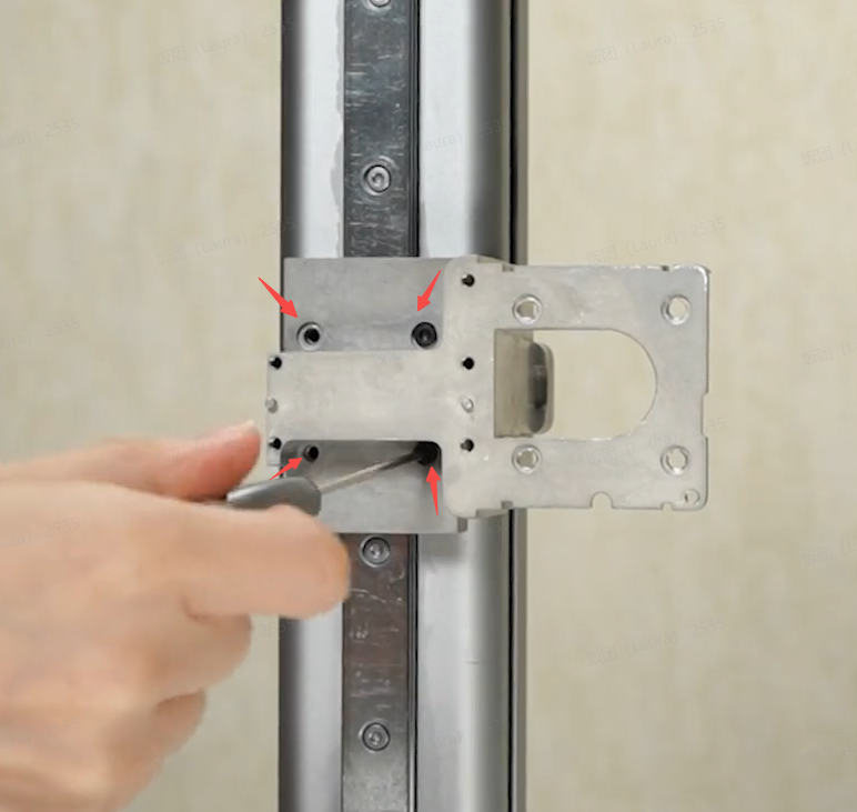
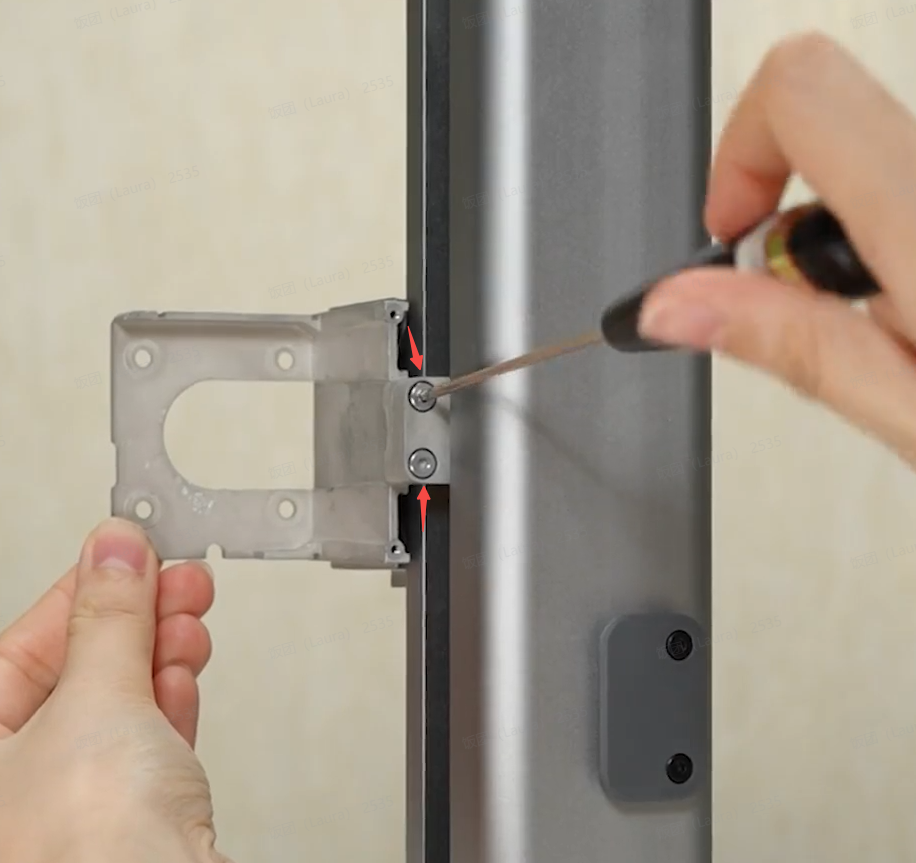
Remove 4 screws J, take down the X-axis module; remove 4 silver screws, remove 2 screws K, and take down the adapter bracket.
 |
 |
 |
¶ Step 7: Remove the Y-axis Linear Rail
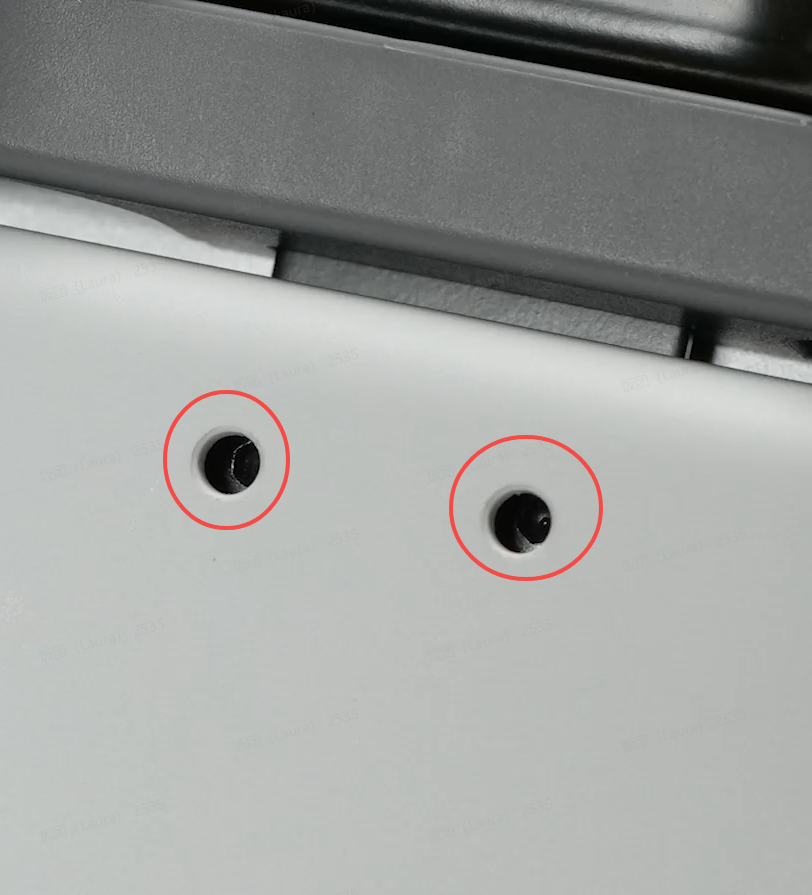
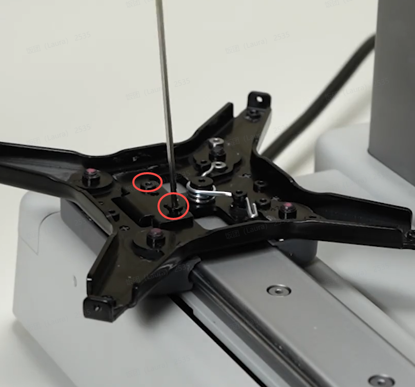
Push the heatbed bracket backward to expose the 2 screws on the connecting plate and loosen the screws completely, then remove the 2 screws L on the pulley and take down the connecting plate;
 |
 |
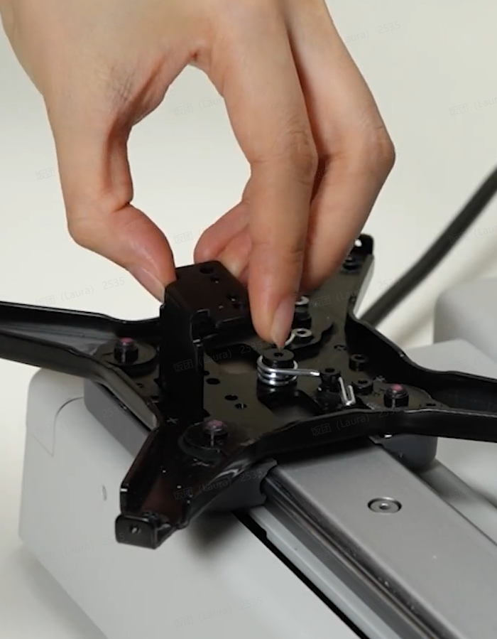 |
Remove 2 screws M and take off the Y-axis rear cover.
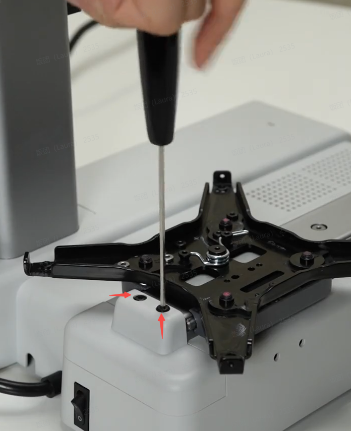 |
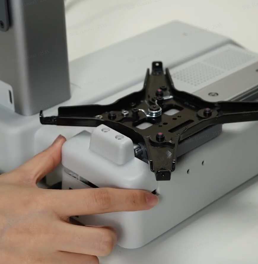 |
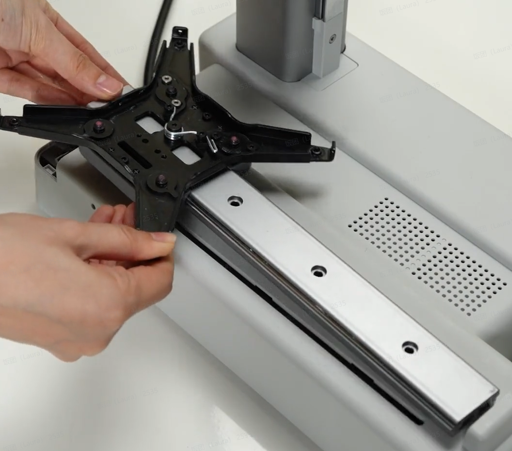
Remove 4 screws N and remove the Y-axis linear rail.
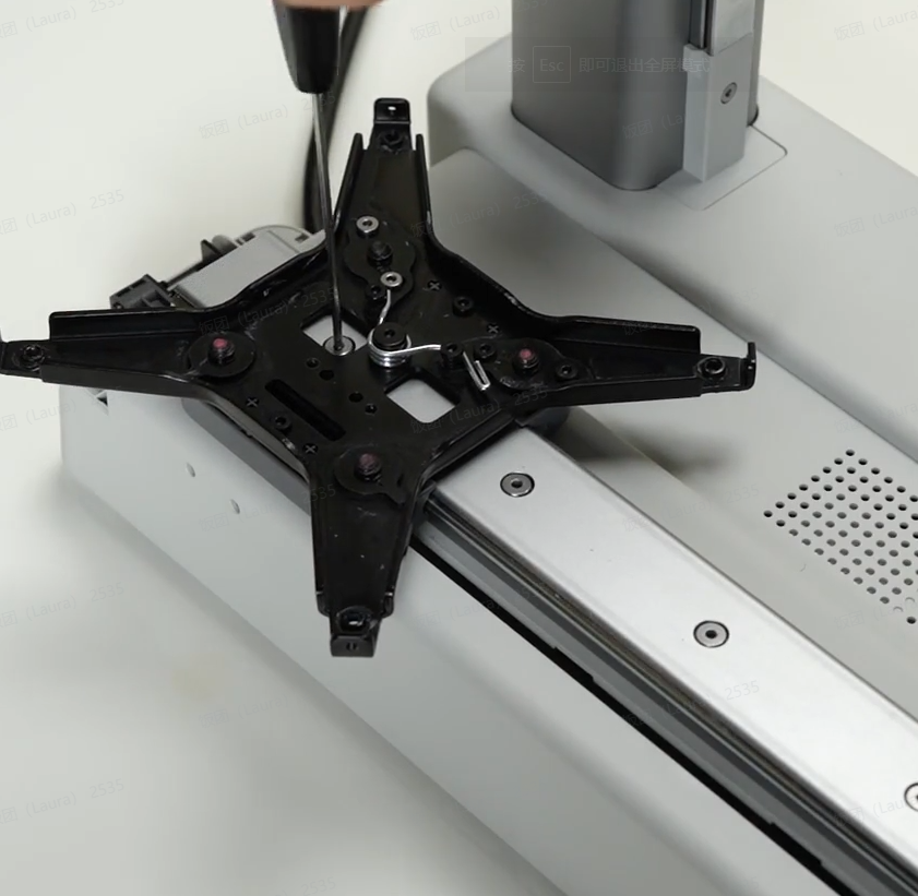 |
 |
¶ Assembly Guide
¶ Step 1: Install the Y-axis Linear Rail
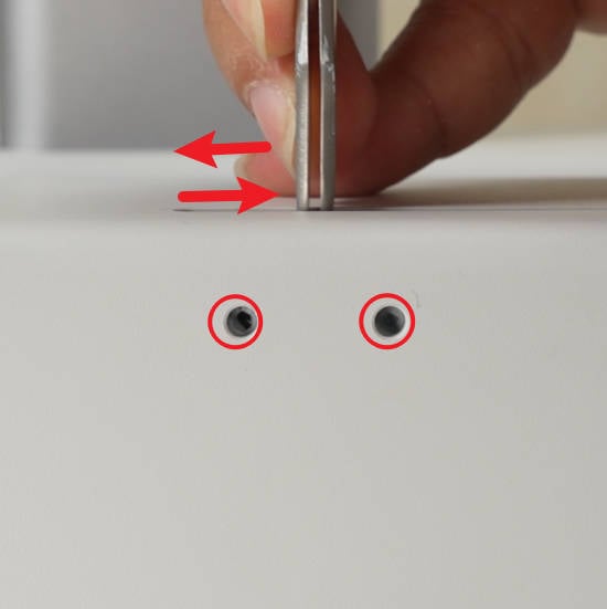
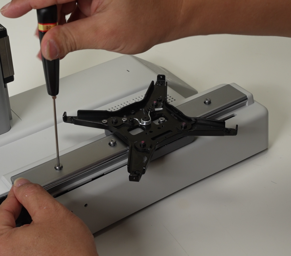
Use tweezers to move the Y belt pressing block to expose the 2 screws. Confirm the installation direction according to the installation position of the connecting plate, place the Y-axis linear rail on the base, align the screw holes, put in 4 screws N, and lock them alternately;
 |
 |
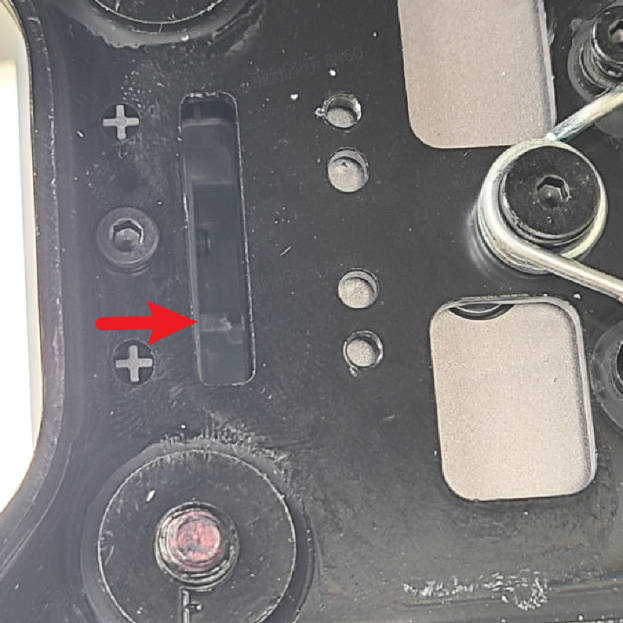
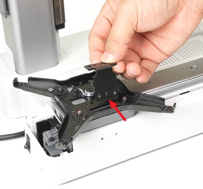
Move the heatbed bracket to expose the Y-axis belt block, then install the connecting plate, confirm that it is in place, and lock 2 screws L to fix the connecting plate;
 |
 |
 |
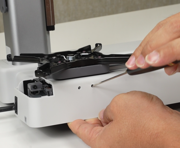
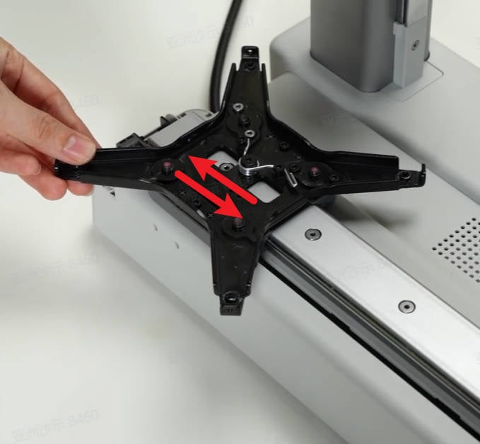
Then tighten the 2 screws through the base, move the heatbed bracket, and confirm that the heatbed bracket can drive the Y belt to move smoothly.
 |
 |
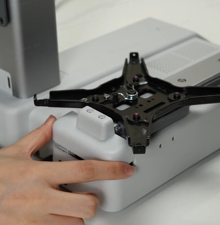
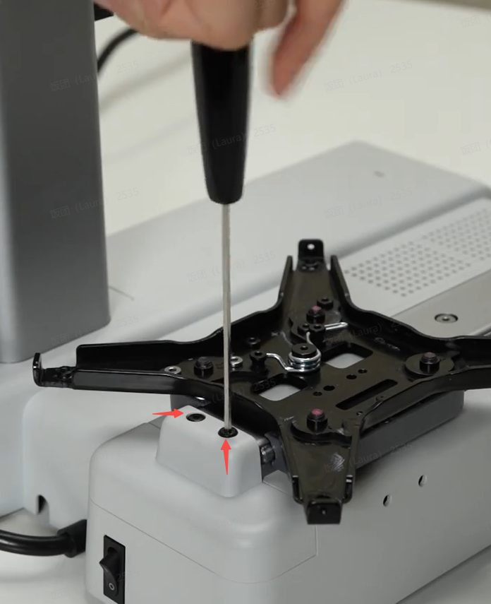
Install the Y-axis rear cover, and lock in 2 screws M.
 |
 |
¶ Step 2: Install the X-axis assembly.
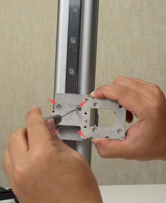
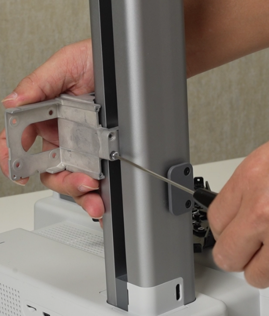
Install the adapter bracket, lock 4 silver screws on the front and 2 screws K on the back;
 |
 |
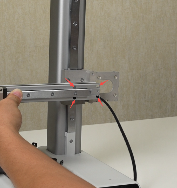
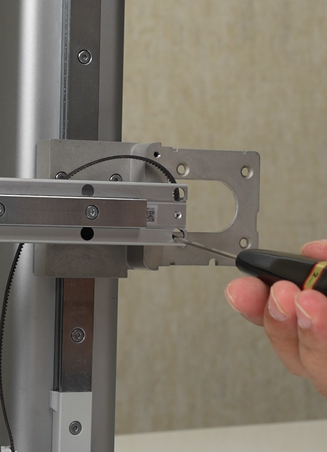
Install the X-axis module, taking care to prevent the X slider from falling off, and then lock the 4 screws J. Be careful not to press the X-axis timing belt when tightening the lower 2 screws.
 |
 |
¶ Step 3: Install the X motor
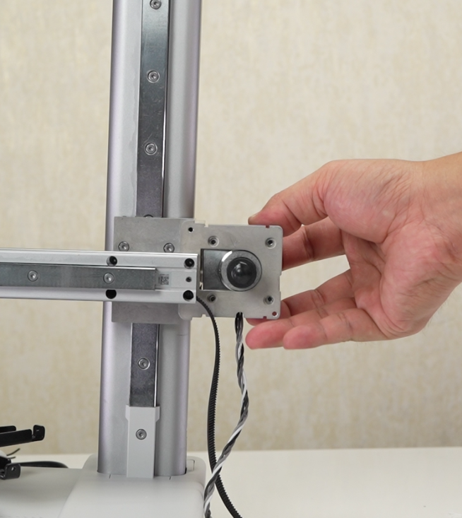
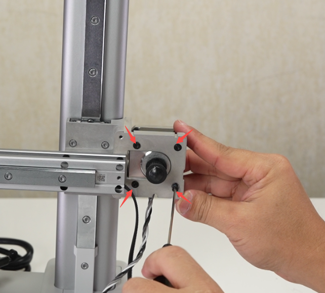
Install the X motor with the motor cable facing downwards and lock in the 4 screws G.
 |
 |
¶ Step 4: Install the X motor cover, camera, and USB cable
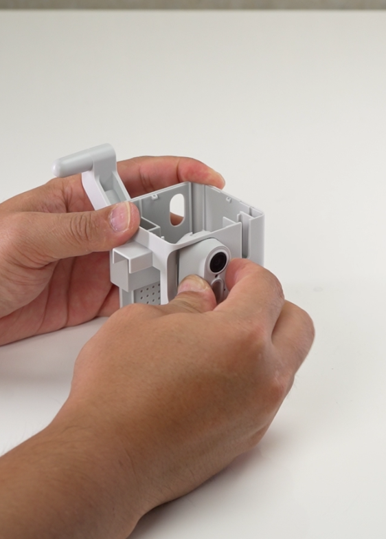
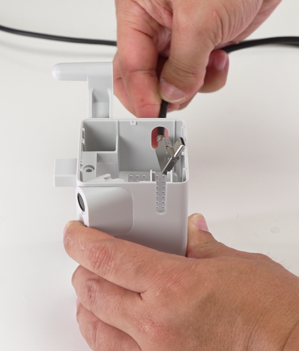
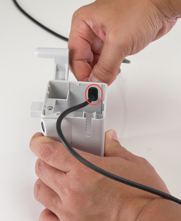
Install the camera onto the motor cover. Thread the USB cable and fasten it to the motor cover.
 |
 |
 |
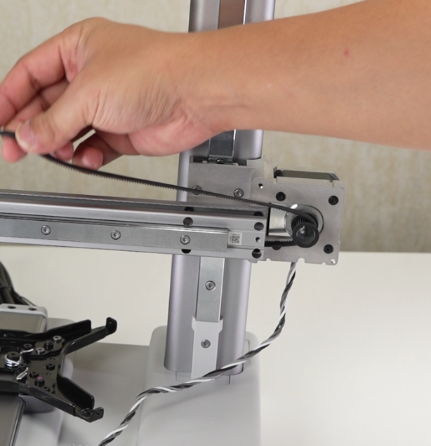
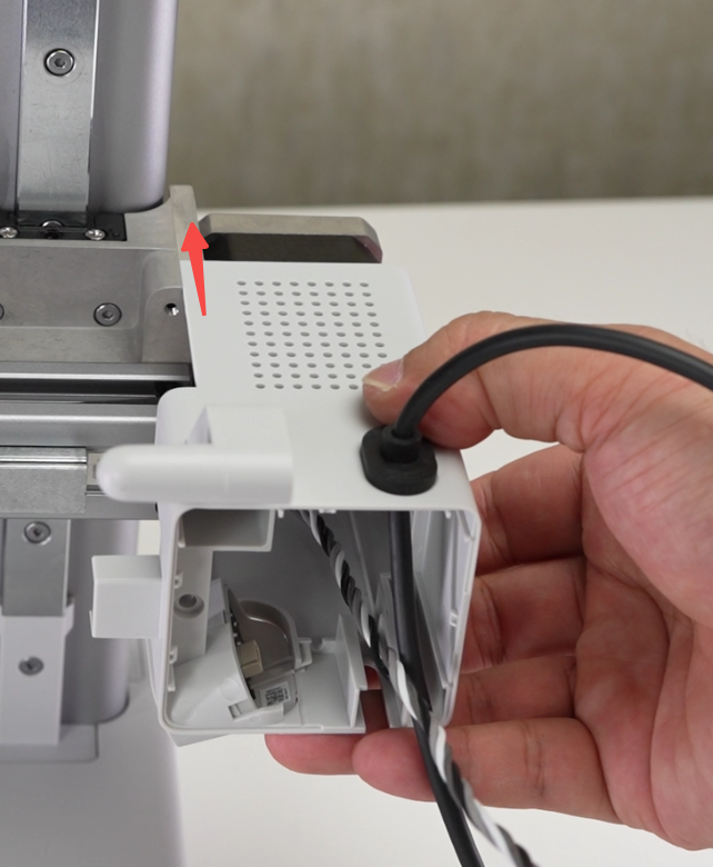
Pass the X-axis synchronous belt around the motor driving wheel, and then install the motor cover to the adapter bracket in the direction of the arrow. Note that the motor cable must pass through the motor cover. Lock 1 screw F on the X-axis and lock it inside the motor cover. 2 screws G secure the motor cover;
 |
 |
 |
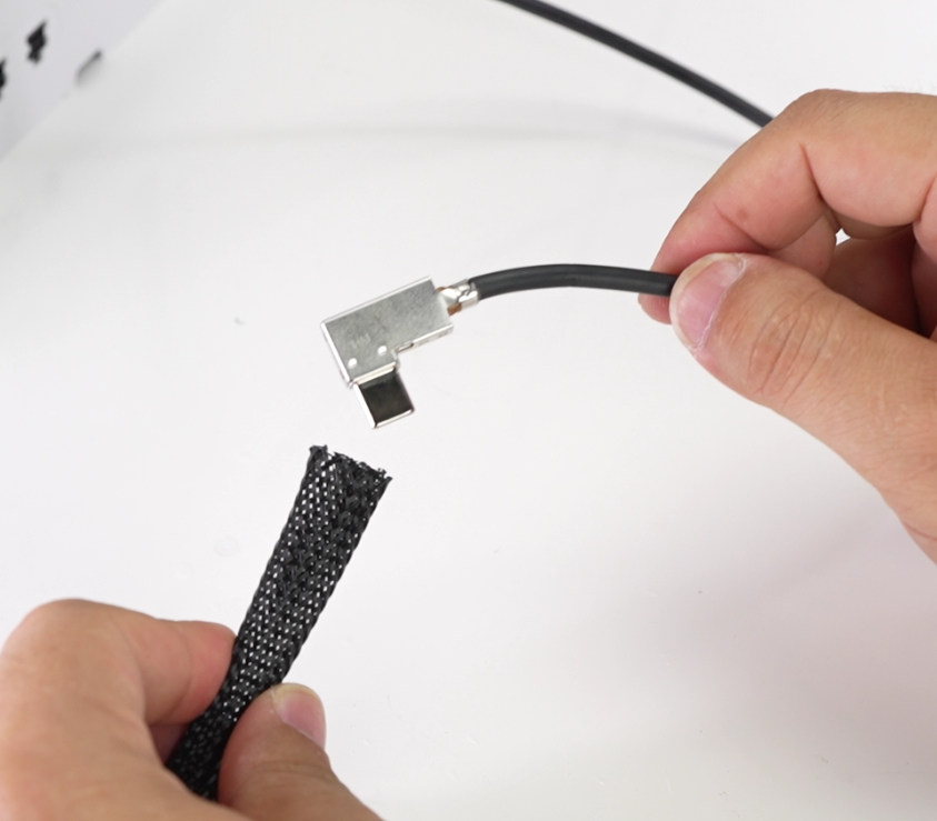
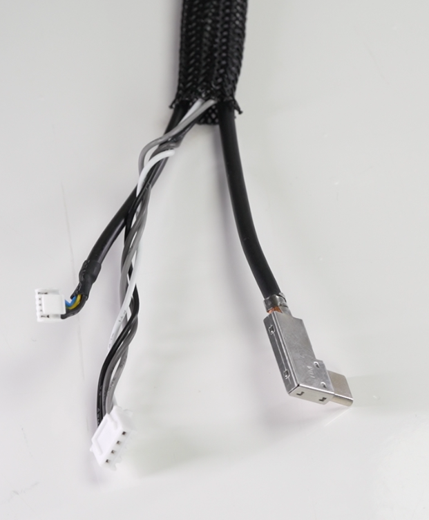
Connect the small end of the camera cable to the camera, and then pass the USB cable, X motor cable and camera cable through the nylon mesh in sequence;
 |
 |
 |
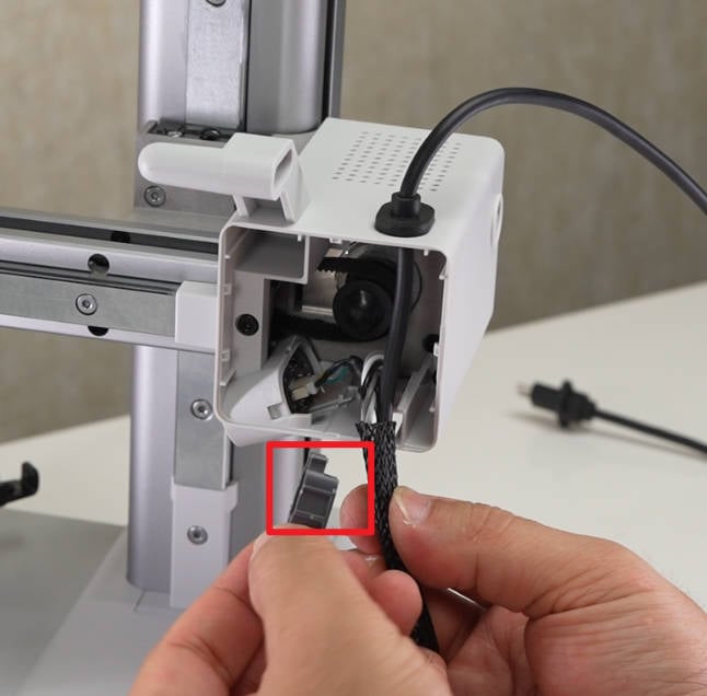
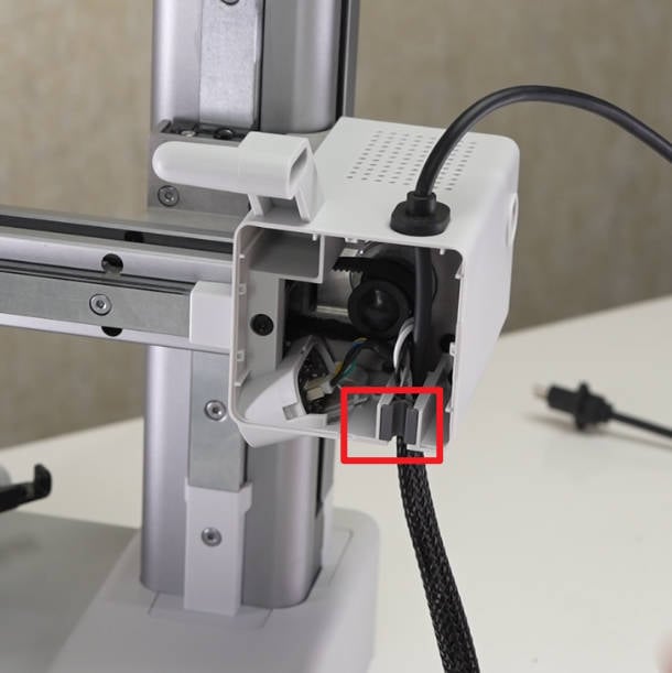
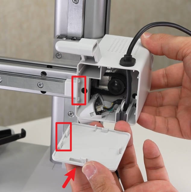
Confirm the direction of the wire clamp, install the wire clamp on the motor cover, then confirm the installation direction, and cover the front cover of the motor cover;
 |
 |
 |
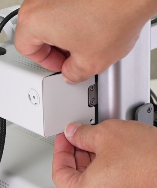
Install the rear cover of the X motor cover , lock in 2 screws H, align the installation position, and install the PTFE Tube Connector;
 |
 |
 |
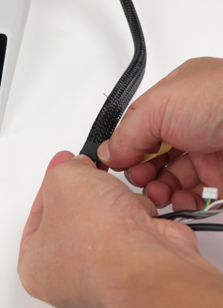
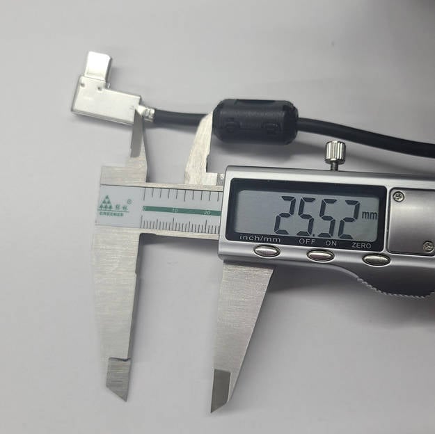
Wrap the other end of the nylon mesh with tape and install a ferrite cores about 25 mm away from the USB connector.
 |
 |
¶ Step 5: Install the Heatbed.
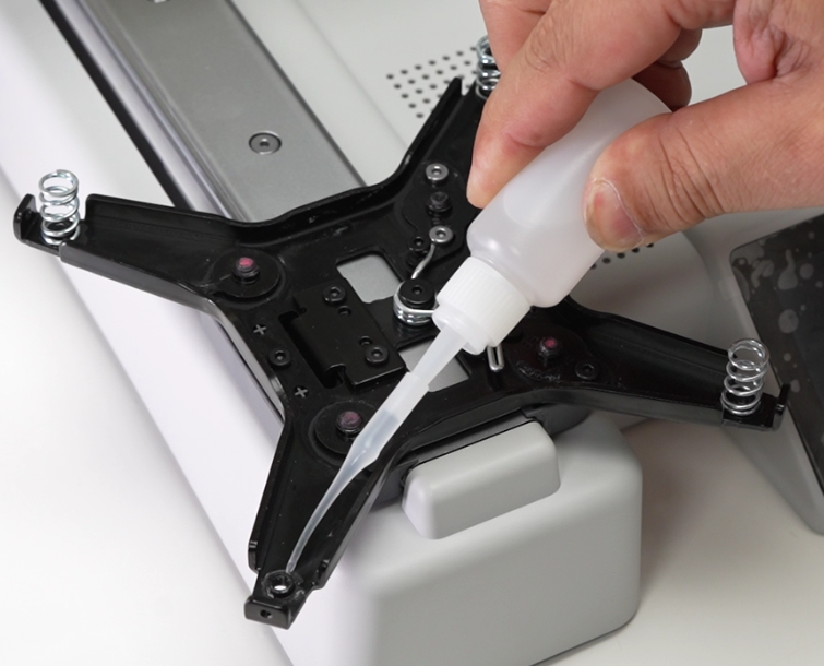
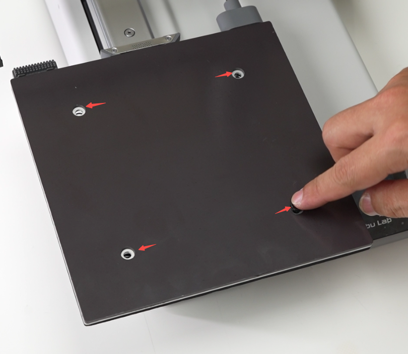
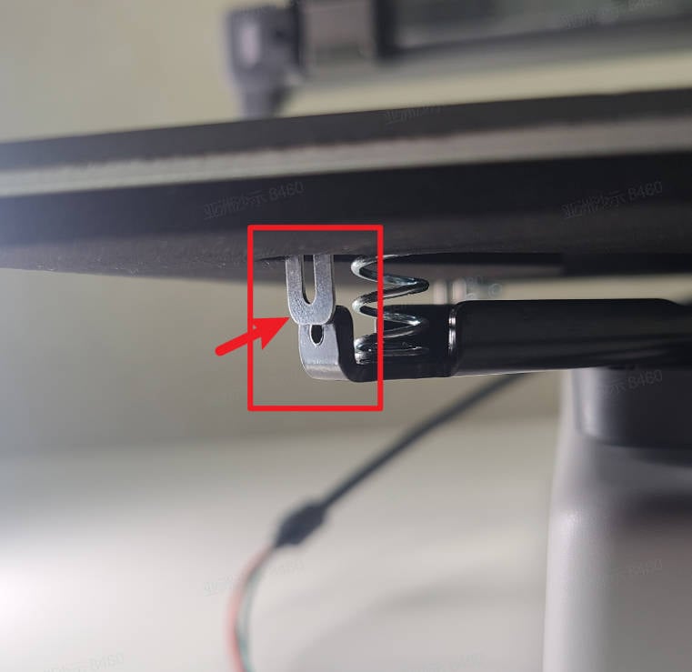
Pre-fix the four springs to the corresponding positions with glue, align the spring positions, place the heatbed, and confirm from the bottom of the heatbed that the three fixing pieces on the heatbed are all on the outside of the heatbed bracket;
 |
 |
 |
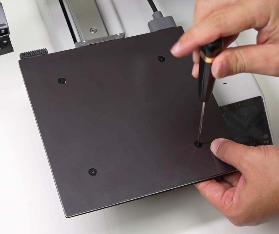
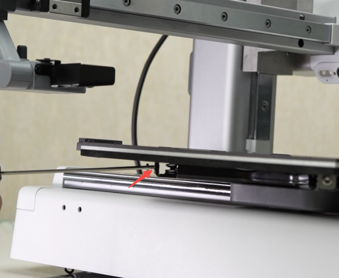
Insert 4 leveling screws E and compress the leveling spring of the heatbed by hand so that the leveling screws can be locked. After all are locked, loosen the 4 leveling screws by 1 turn; install 3 heatbed secure screws D, but do not tighten them. These 3 screws need to be tightened after completing the manual leveling of the heatbed;
 |
 |
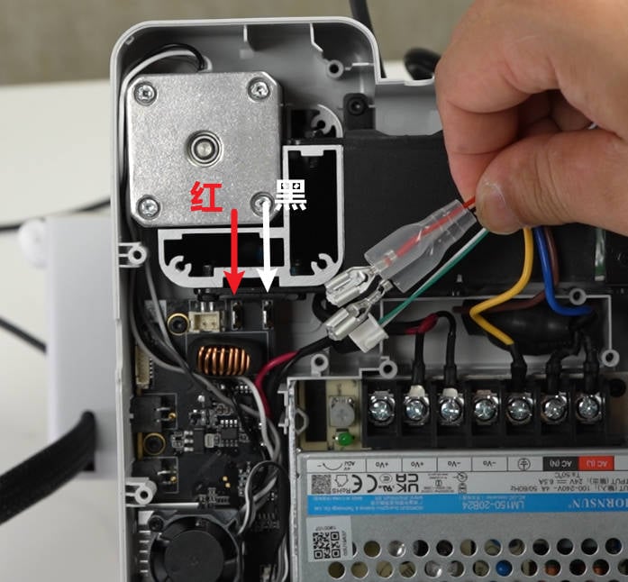
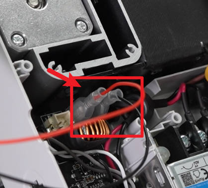
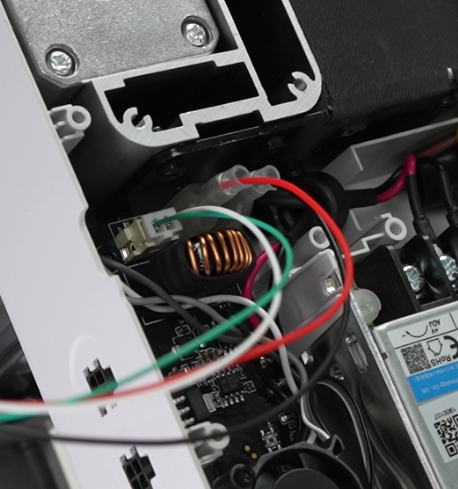
Tilt the printer backwards, then connect the heatbed power cord as shown in the picture, pay attention to distinguish the red and black cables, install the insulating rubber sleeves, and then connect the heatbed signal cable;
 |
 |
 |
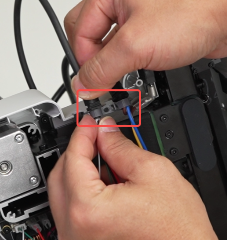
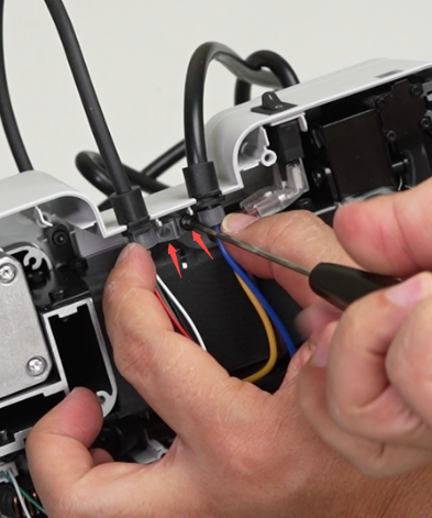
Install the cable buckle and use 2 screws A to lock the heatbed wire and power cable;
 |
 |
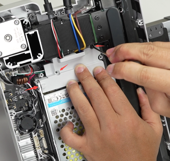
Arrange the heatbed cables and power cable, install the fireproof cover, confirm that the cables are not pressed, and then lock in the 3 screws B.
¶ Step 6: Connect the cables
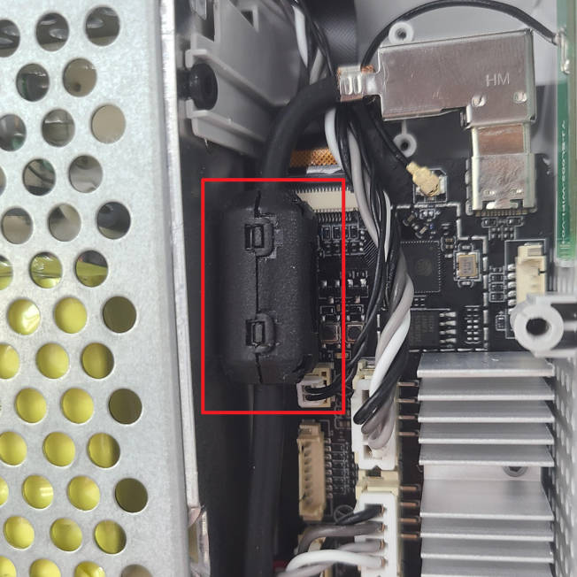
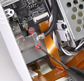
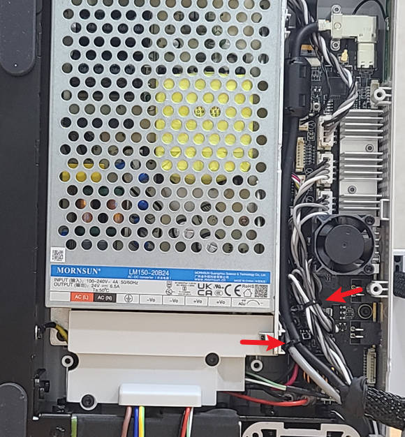
Connect the X motor cable and camera cable to the mainboard, connect the USB cable, after confirming the location of the ferrite cores, lock the pressing piece with 2 screws C. Arrange the cables and tie them with small zip ties.
There are two versions of the USB-C ferrite cores: the split/separated structure shown in the image and an integrated one-piece ferrite core.
If it is the integrated one-piece structure, you do not need to install the separated/split type of ferrite core onto the cable, as the ferrite core is already integrated into the cable.
The two versions are shipped randomly. The final product received should be considered the authoritative version.
 |
 |
 |
 |
¶ Step 7: Install the Baseplate
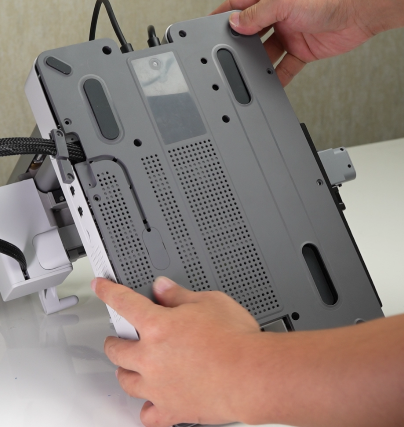
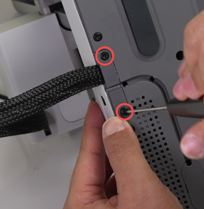
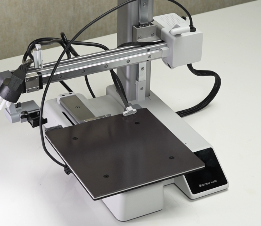
Install the baseplate, align the position, and lock in 14 screws B to fix it; then install the cable clamp, lock in 2 screws A to fix it; place the printer upright.
 |
 |
 |
¶ Verify the functionality
After installing the tool head, connect the USB cable, start the printer, and confirm that the printer can start normally and the screen can display normally.
¶ Calibration
After disassembling and assembling the heatbed, you need to manually level the heatbed. Please click on Manual Leveling of the Heatbed for specific operations;
End Notes
We hope that the detailed guide we shared with you was helpful and informative.
We want to ensure that you can perform it safely and effectively. If you have any concerns or questions regarding the process described in this article, we encourage you to reach out to our friendly customer service team before starting the operation. Our team is always ready to help you and answer any questions you may have.
Click here to open a new ticket in our Support Page.
We will do our best to respond promptly and provide you with the assistance you need.