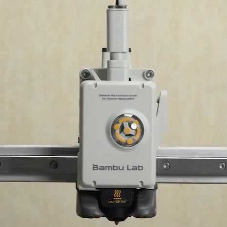
This article offers guidelines and precautions for disassembling and assembling the A1 Series Toolhead. It also includes instructions for removing and replacing replaceable parts.
If A1 replaces the extruder mainboard of A1mini, the firmware upgrade may fail. If this happens, please click here to submit a technical ticket and for resolution.
It's crucial to power off the printer before conducting any maintenance work, including work on the printer's electronics and tool head wires. Performing tasks with the printer on can result in a short circuit, leading to electronic damage and safety hazards.
During maintenance or troubleshooting, you may need to disassemble parts, including the hotend. This exposes wires and electrical components that could short circuit if they contact each other, other metal, or electronic components while the printer is still on. This can result in damage to the printer's electronics and additional issues.
Therefore, it's crucial to turn off the printer and disconnect it from the power source before conducting any maintenance. This prevents short circuits or damage to the printer's electronics, ensuring safe and effective maintenance. For any concerns or questions about following this guide, open a new ticket in our Support Page and we will do our best to respond promptly and provide the assistance you need.
If the filament is in the loading status, please use the filament cutter to cut it off first.
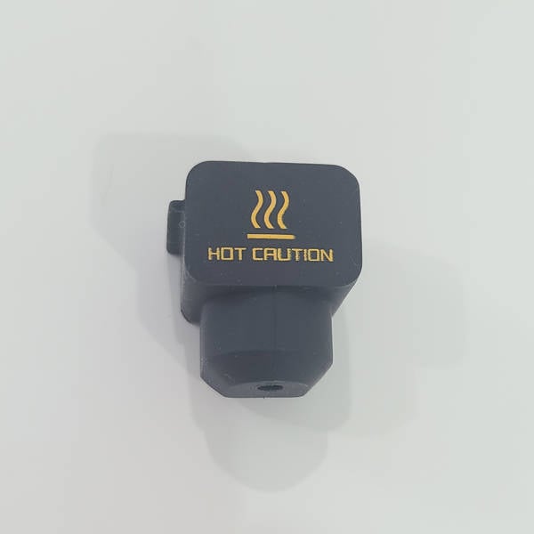
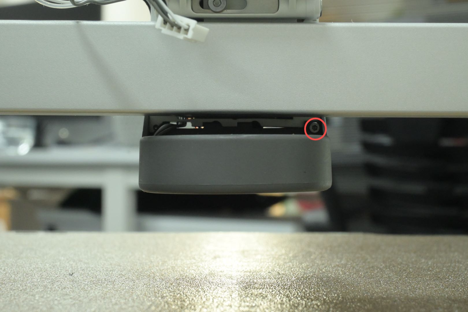
Press the Toolhead Cover from both sides to unlock and remove the cover, being careful not to press on the Cooling Fan for Hotend. Pull the protrusion on the side of the Silicone Sock for Hotend with your hands, and remove the Silicone Sock for Hotend.
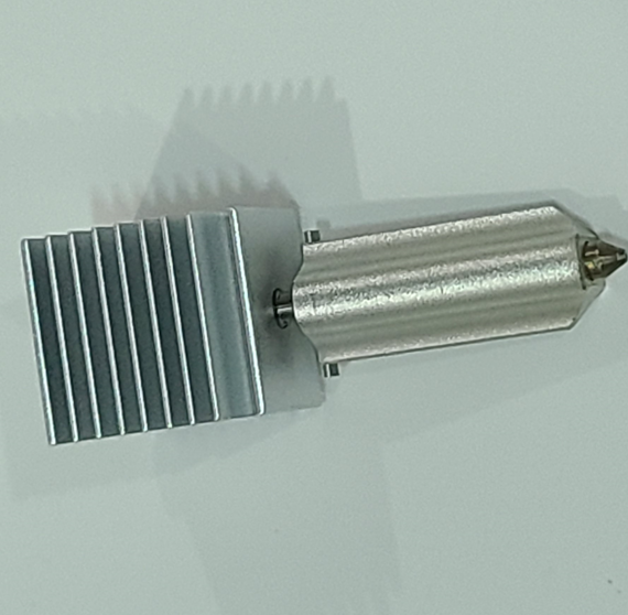
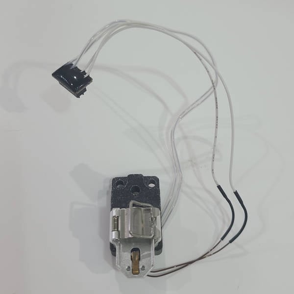
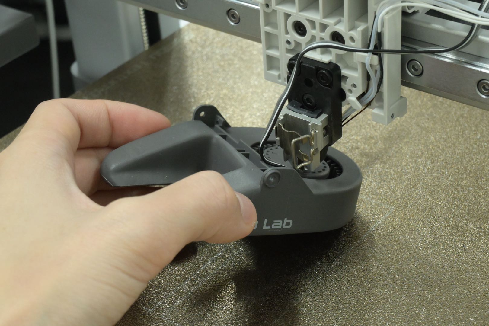
Release the hotend latch, then hold the heat sink with your hands and remove the hotend.
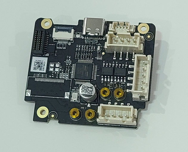
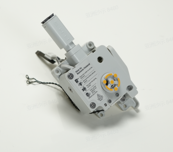
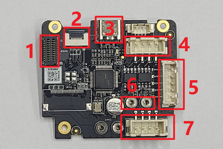
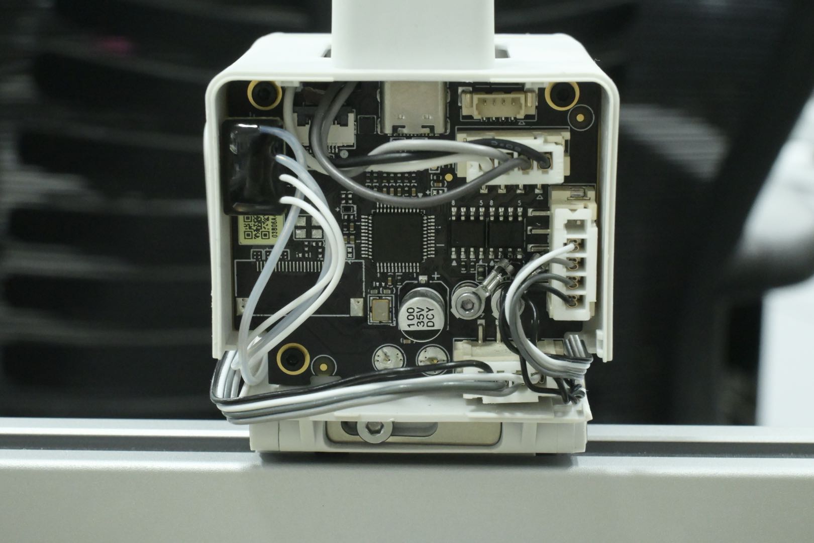
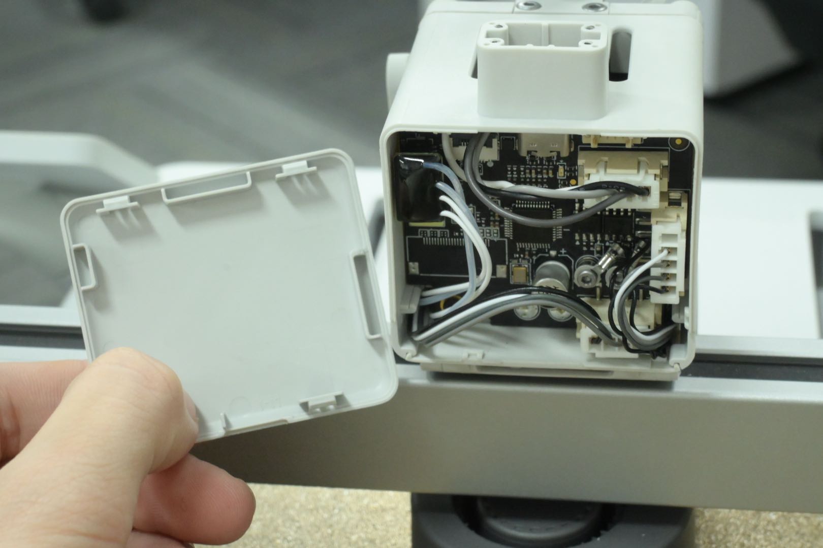
Please refer to the description of each connector in the following figure to understand their function:
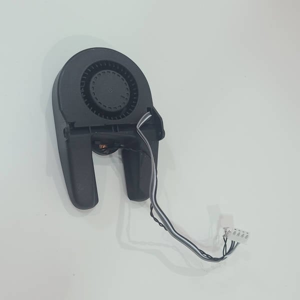
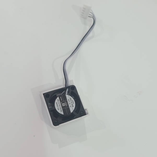
1. Hotend Heating Assembly; 2. Filament sensor; 3. USB Cable; 4. Extruder Motor; 5. Cooling Fan for Hotend; 6. Eddy Current Coil; 7. Part Cooling Fan.
1. Disconnect the 4 connectors for the Hotend Heating Assembly, Extruder Motor, Part Cooling Fan, and Cooling Fan for Hotend one by one. Then, unscrew the 2 Screws B with an H1.5 Allen key and loosen the eddy current coils.
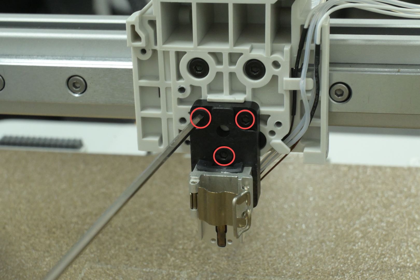
2. Unscrew the 3 screws C with an H1.5 Allen key, remove the TH Board, and loosen and disconnect the Filament Sensor FPC Cable.
1. Unscrew the belt tensioning screws I and the anti-rotation plate using an H2.0 Allen Key. Loosen a total of 4 belt block fixing screws J on the left and right sides to loosen the belt.
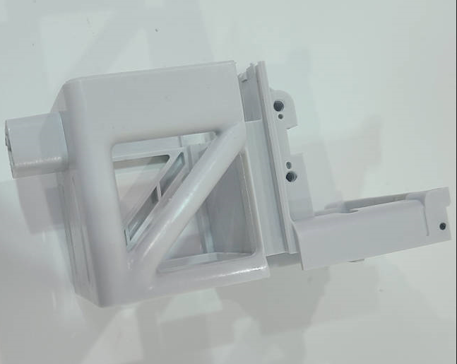
2. Remove the Toolhead Block by unscrewing the 4 screws K with an H2.0 Allen key.
Note: Before installing the extruder, check whether the cables on both sides (eddy current coils and cooling fan for hotend cable on the left; part cooling fan cable and hotend heating assembly cable on the right) are well organized to avoid damage caused by squeezing the cables when installing the extruder. A broken eddy current coil may cause abnormal zero return, and a broken part cooling fan may cause a short circuit and fail to start.
Install the Extruder Module onto the Toolhead Block, being careful not to press on the connecting wires, and secure it with 2 screws D at the top and 2 screws E at the bottom.
1. Connect and snap the Filament Sensor FPC Cable to the corresponding connectors on the TH Board.
2. Mount the TH Board onto the Toolhead, being careful not to press on other cables, and then tighten the 3 screws C to secure the TH Board.
3. Lock the 2 screws B to secure the coil connection wires. Connect the Hotend Heating Assembly, Extruder Motor, Cooling Fan for Hotend and Part Cooling Fan cables in sequence to the corresponding connectors on the TH Board.
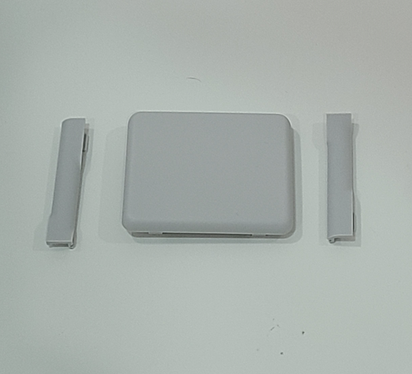
¶ Step 6 - Install the Cable Covers and Toolhead Rear Cover
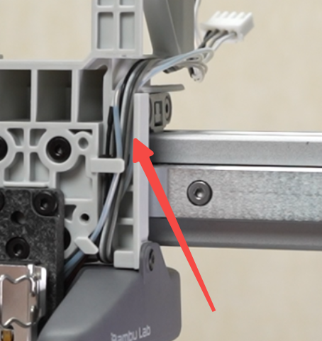
1. After ensuring that the cables are properly placed in the cable channel, check to confirm that the installation direction of cable cover is correct, and then securely install the cable covers on both sides.
2. Check the position of the Toolhead Rear Cover notch and press the cover into place after confirming that the installation direction is correct.
Connect the USB cable to the through-hole above the Toolhead following the direction of the cable slot, and tighten the 4 screws A to secure it in place.
1. Open the quick-release device, hold the nozzle heat sink, align the mounting position, install the nozzle in place, and snap the quick-release device closed.
2. Put on the Silicone Sock for Hotend and install the Toolhead Front Cover.