¶ X motor
The X motor is a stepper motor mounted on the X-axis of the printer that drives the toolhead in the X-axis.
¶ What to use?
- X motor is burned out
- After analyzing the logs, official technical support confirmed that the X motor is faulty.
¶ Safety warning
Important!
It's crucial to power off the printer before conducting any maintenance work, including work on the printer's electronics and tool head wires. Performing tasks with the printer on can result in a short circuit, leading to electronic damage and safety hazards.
During maintenance or troubleshooting, you may need to disassemble parts, including the hotend. This exposes wires and electrical components that could short circuit if they contact each other, other metal, or electronic components while the printer is still on. This can result in damage to the printer's electronics and additional issues.
Therefore, it's crucial to turn off the printer and disconnect it from the power source before conducting any maintenance. This prevents short circuits or damage to the printer's electronics, ensuring safe and effective maintenance.
For any concerns or questions about following this guide, please open a new ticket in our Support Page and we will do our best to respond promptly and provide the assistance you need.
¶ Tools and materials needed
- X motor for Bambu Lab A1 mini(purchase link: X Motor - A1 mini )
- H2.0 hex wrench
- H1.5 hex wrench
- Wire cutters
¶ Remove X motor
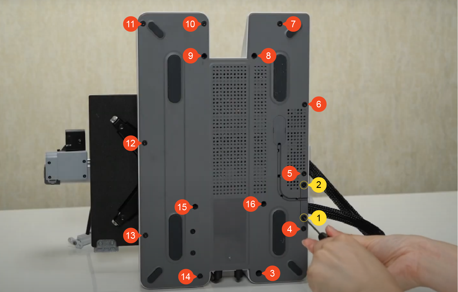
¶ Step 1: Remove the baseplate
Tilt the printer backward until the Z-axis pillars make contact with the table surface.
Use a H2.0 hex wrench to remove the 2 screws (BT2.6×8), then remove the 14 screws (BT3×8). Pull the nylon mesh to loosen the baseplate, and then remove the baseplate.
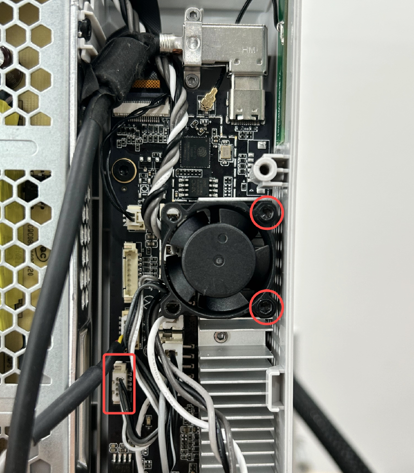
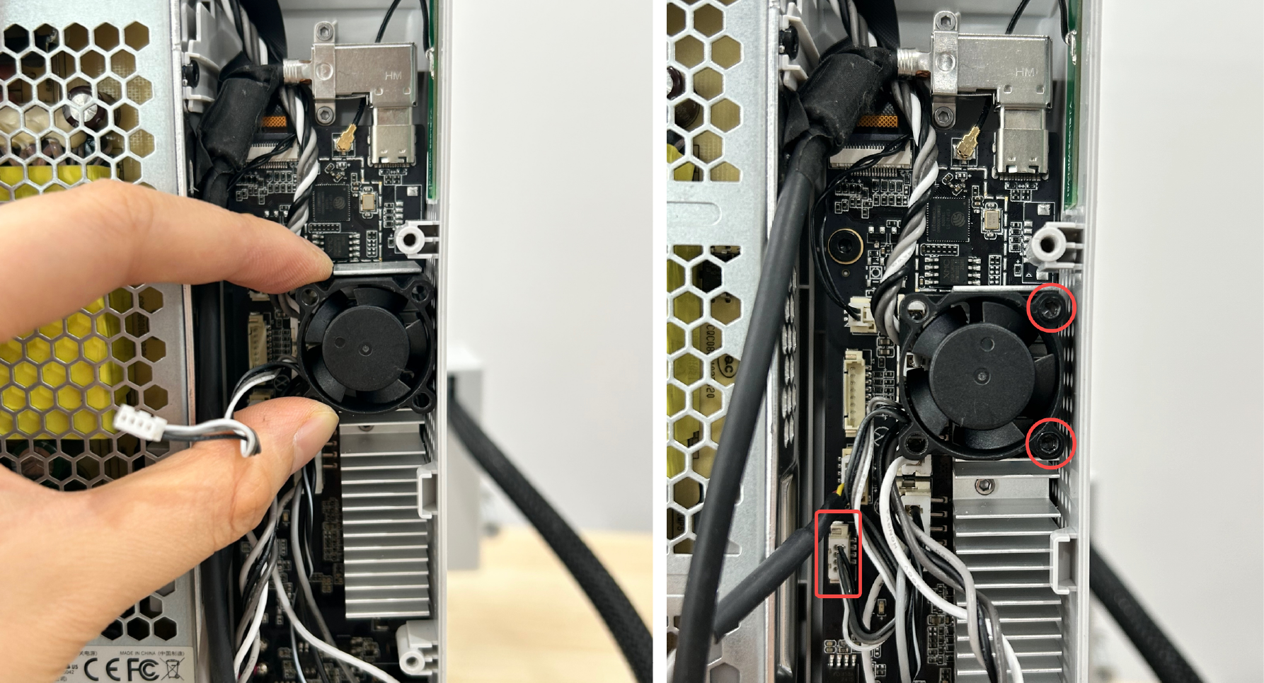
¶ Step 2: Remove the main board fan
Use the H2.0 hex wrench to remove 2 screws (MG2.5×15),and disconnect the main board fan cable.
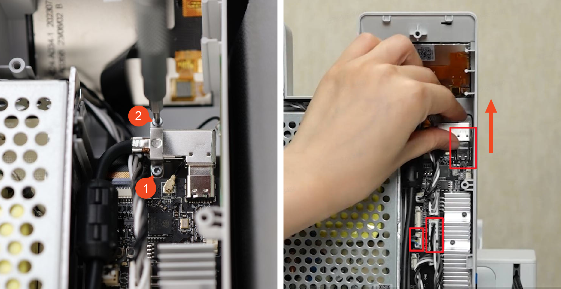
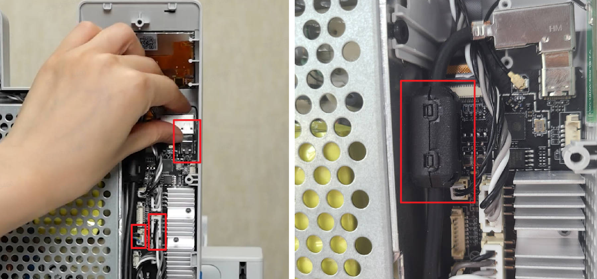
¶ Step 3: Disconnect the cables
Remove 2 screws (BT2×5) and plate, and disconnect the USB cable, camera cable, and X motor cable from the mainboard. Note that the camera cable has a latch. Press to release it before disconnecting.
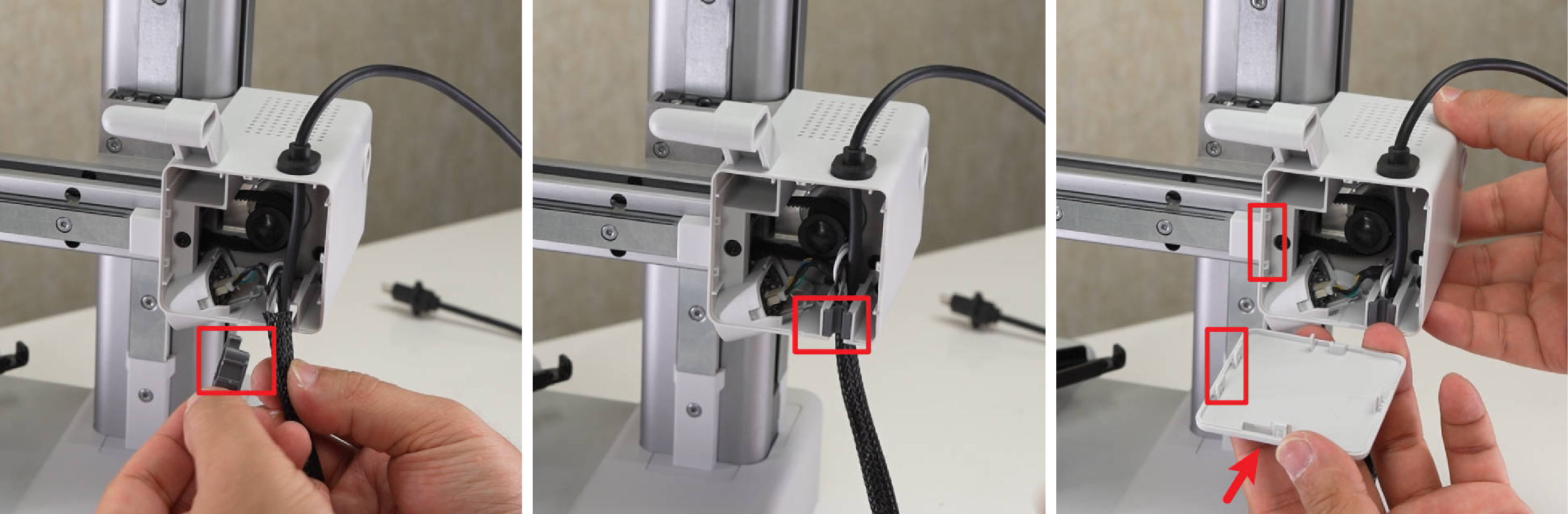
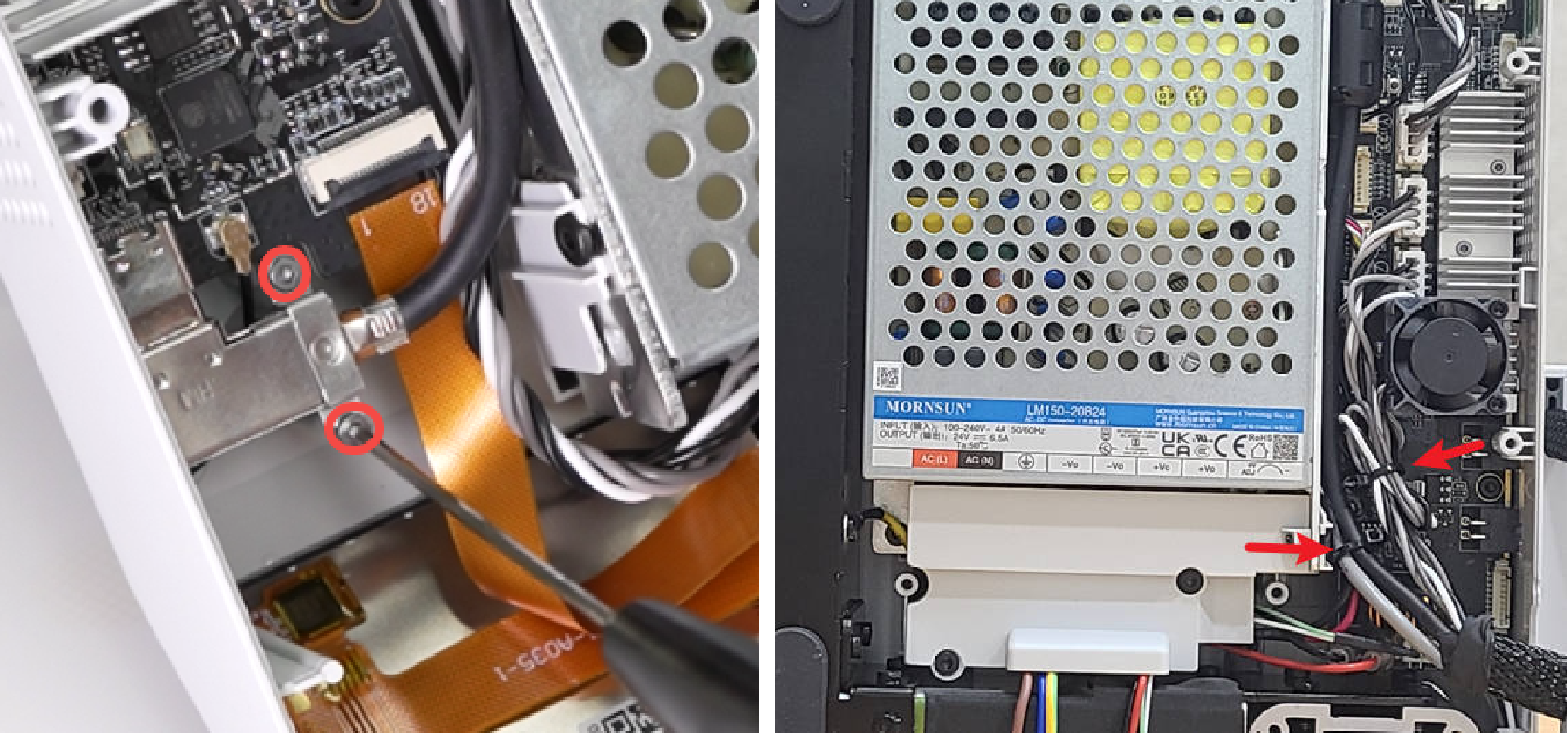
¶ Step 4: Remove the camera cable and X motor cover
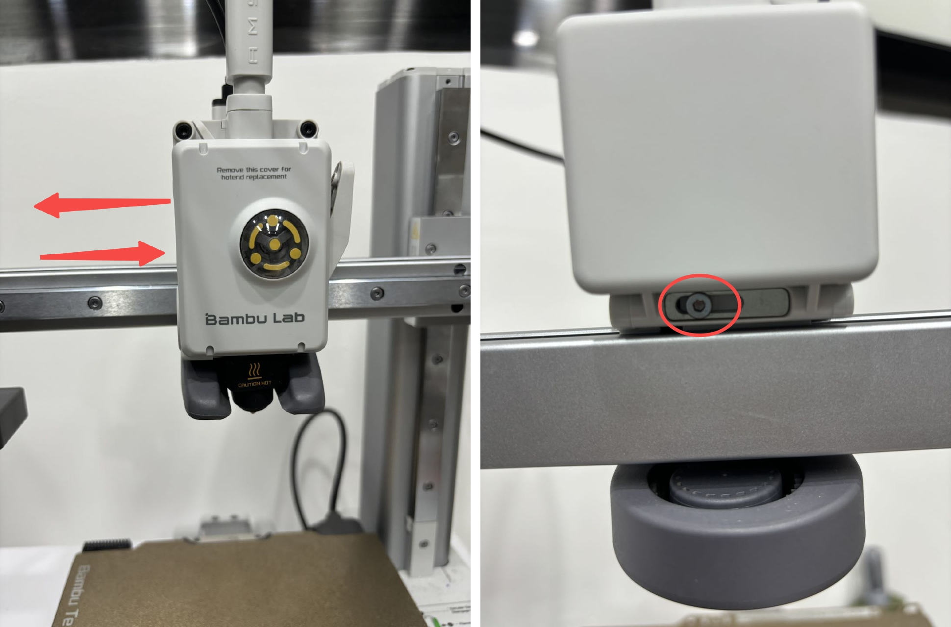
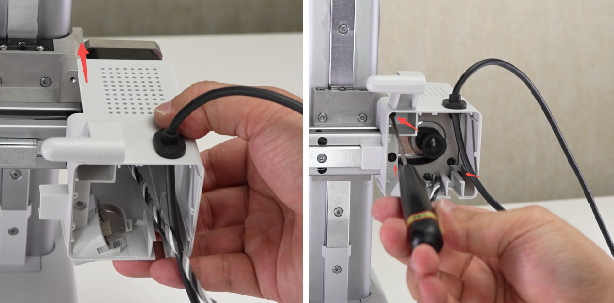
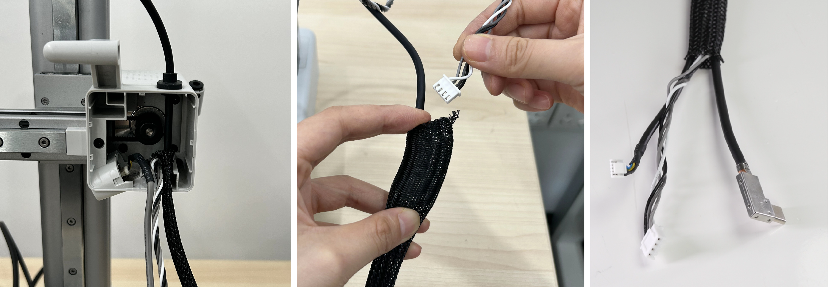
Apply force from below the motor cover front lid to remove it. Disconnect the camera cable. Insert an Allen wrench through the cable clamp and pry it out. Remove the cable clamp.
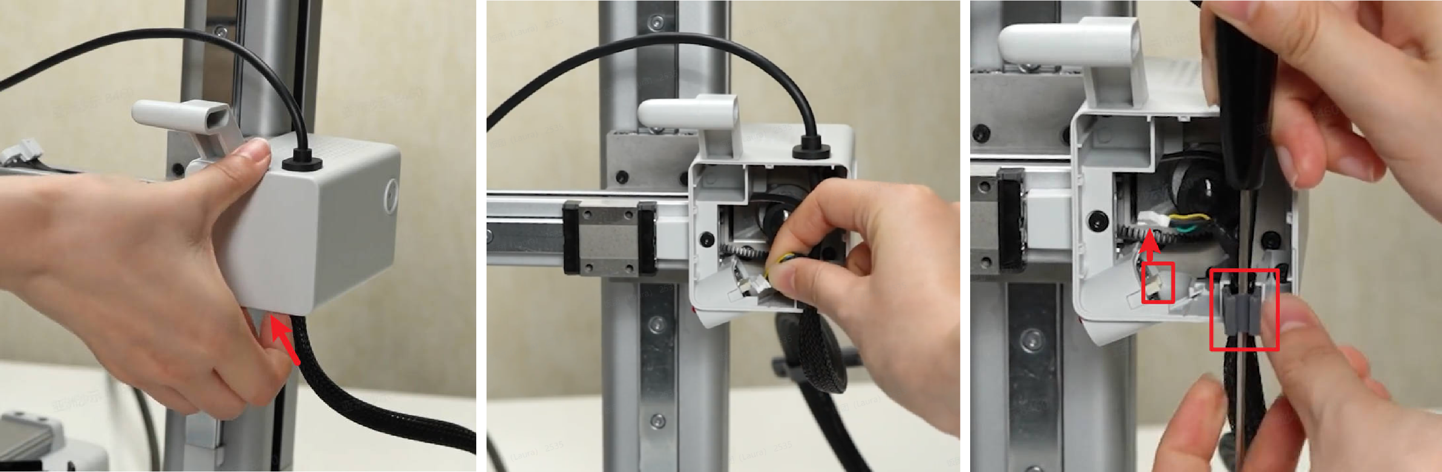
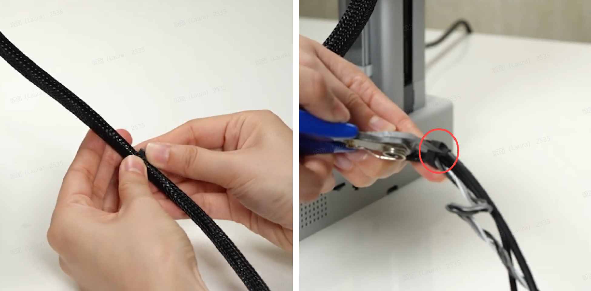
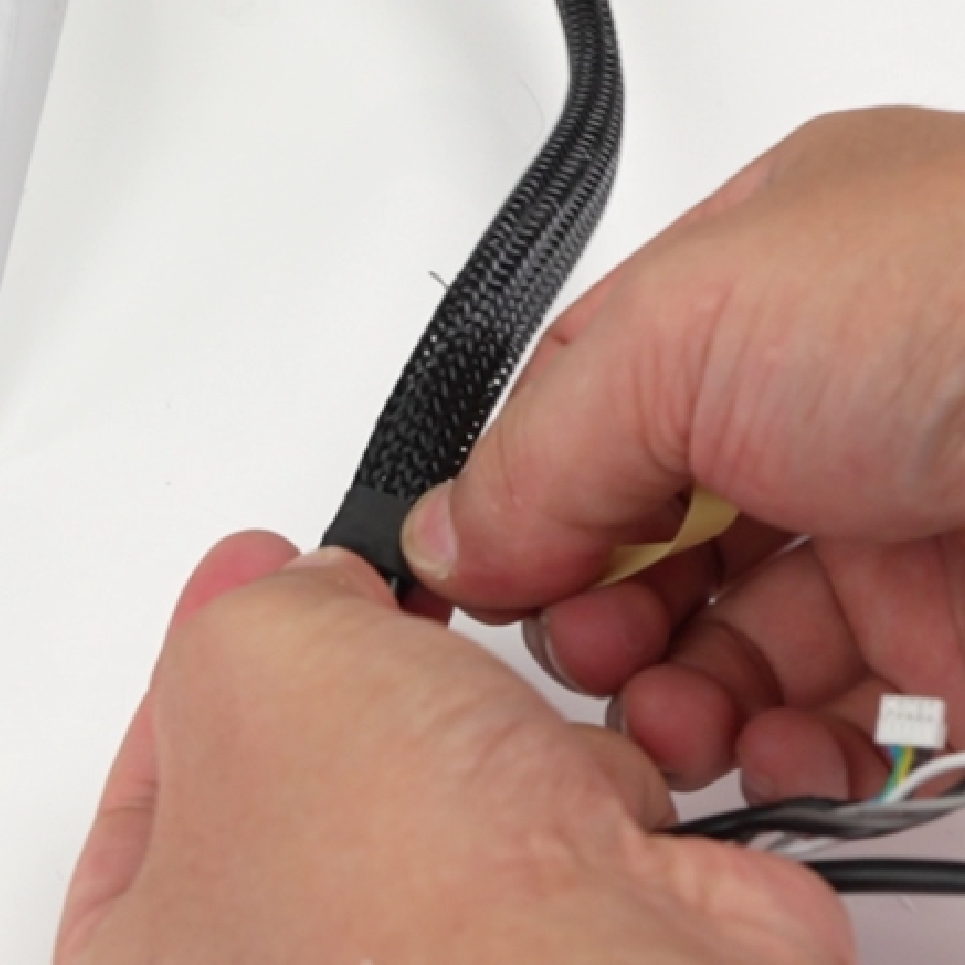
Remove the cable buckle left on the cables, tear off the tape at one end of the nylon mesh, and pull out the camera connection cable and X motor cable;
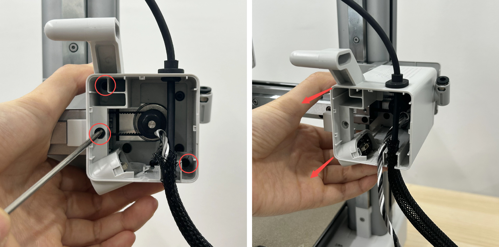
Remove 1 screw (M3×10), 2 screws (M3×6), and take off the X motor cover assembly.
¶ Step 5: Loosen the X belt
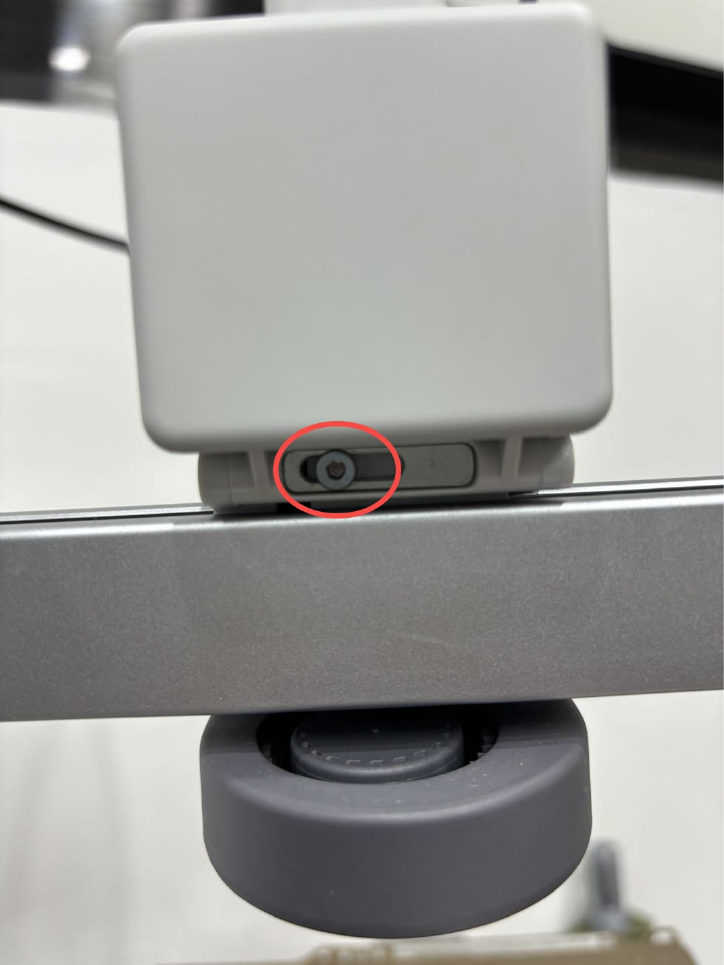
Loosen the tension screw in one turn (do not fully loosen them) to loose the X belt.
¶ Step 6: Remove the X motor
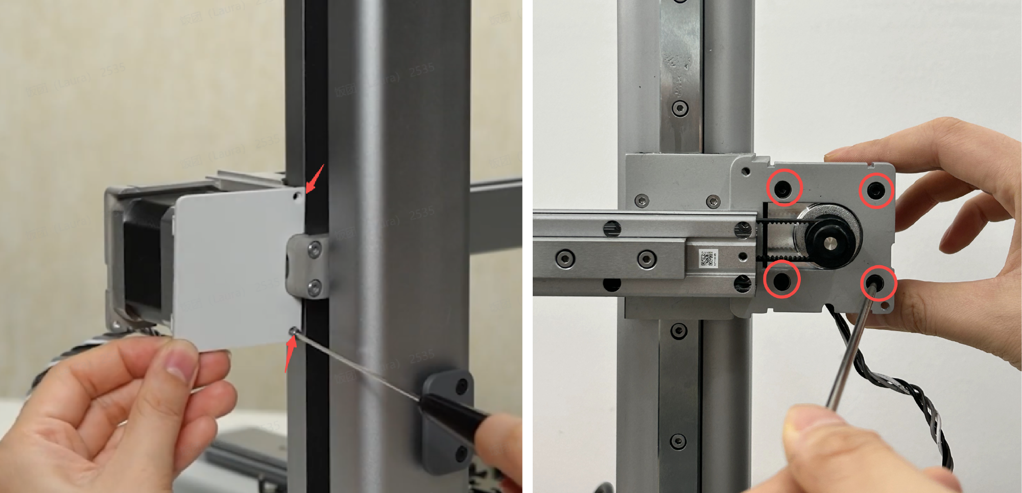
Remove 2 screws (M2×4.5) and remove the motor rear cover. Remove 4 screws (M3×5) and take down the X motor.
¶ Assembly guide
¶ Step 1: Install the X motor
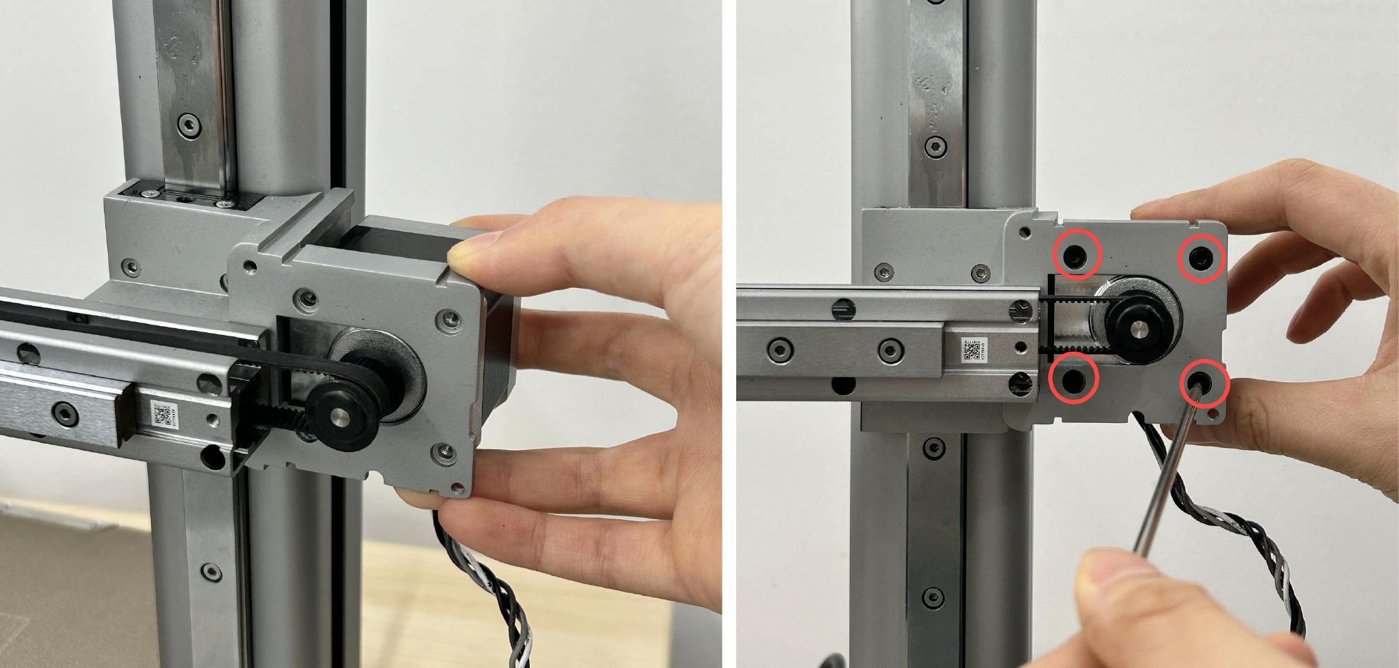
Install the X motor with the motor cable facing downwards. Thread the motor driving wheel through the X belt and lock in the 4 screws (M3×5).
¶ Step 2: Tension the X belt
Move the X-axis to the position close to the middle of the Z-axis to avoid scratching the hotbed when moving the toolhead.
Ensure that the tension screw has been loosened but not fully unscrewed. Move the toolhead back and forth along the X-axis three times by hand, and then re-tighten the tension screw.
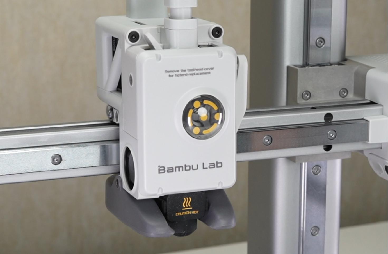
¶ Step 3: Install the X motor cover, camera, and USB cable
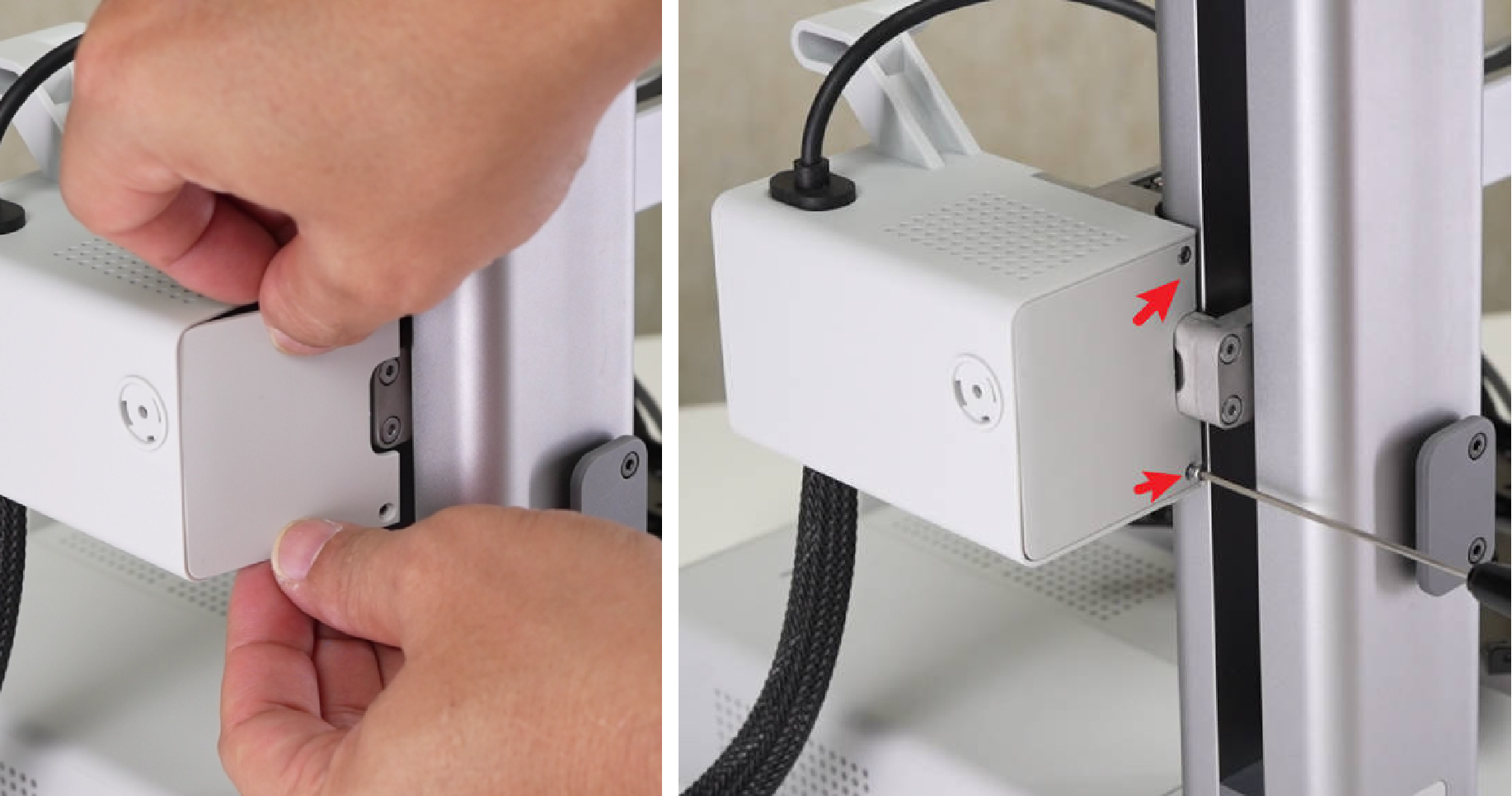
Install the motor cover to the adapter bracket in the direction of the arrow. Note that the motor cable must pass through the motor cover. Lock 1 screw (M3×10) on the X-axis and lock it inside the motor cover. 2 screws (M3×6) secure the motor cover;
Connect the small end of the camera cable to the camera, and then pass the X motor cable and camera cable through the nylon mesh in sequence;
Confirm the direction of the wire clamp, install the wire clamp on the motor cover, then confirm the installation direction, and cover the front cover of the motor cover;
Install the rear cover of the X motor cover , lock in 2 screws (M2×4.5), align the installation position;
Wrap the other end of the nylon mesh with tape.
¶ Step 4: Connect the cables
Connect the X motor cable and camera cable to the mainboard, connect the USB cable, after confirming the location of the ferrite cores, lock the pressing piece with 2 screws (BT2×5).
Arrange the cables properly to ensure the baseplate can be installed smoothly and the mainboard fan will not come into contact with the cables during operation.
¶ Step 5: Install the main board fan
Install the main board fan with the cable facing left. Lock it with two screws (MG2.5×15), and then connect the main board fan cable.
¶ Step 6: Install the Baseplate
Install the baseplate, align the position, and lock in 14 screws (BT3×8) to fix it; then install the cable clamp, lock in 2 screws (BT2.6×8) to fix it; place the printer upright.
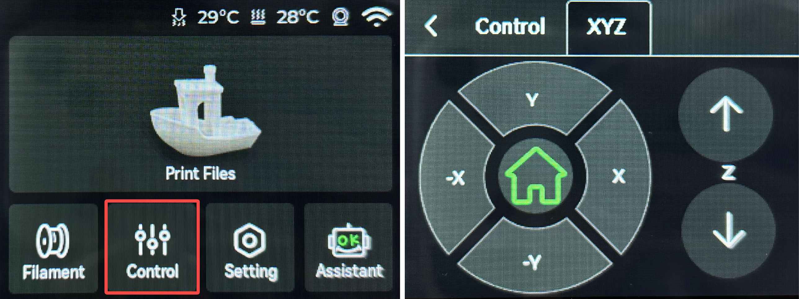
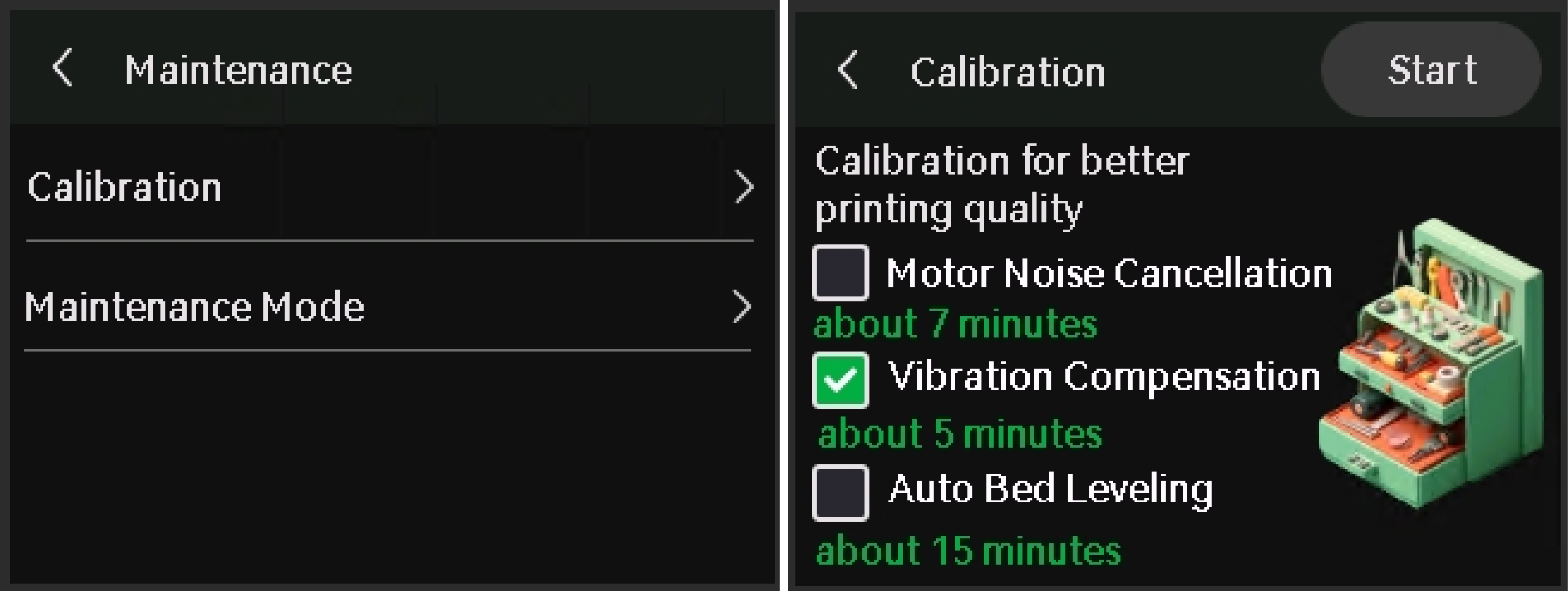
¶ Functionality verification and calibration step
After completing all the assembly steps above, power on the printer, enter the control interface, and click the "-X" or "X" button on the screen to move the X-axis and confirm whether the X motor is functioning properly.
In the Calibration screen, select only Vibration Compensation, and then tap Start.
The calibration will confirm the printer is running as expected.
¶ End Notes
We hope the detailed guide provided has been helpful and informative.
To ensure a safe and effective execution, if you have any concerns or questions about the process described in this article, we recommend submitting a technical ticket regarding your issue.
Please include a picture or video illustrating the problem, as well as any additional information related to your inquiry.