¶ Y motor
The Y motor is a stepper motor mounted on the Y-axis of the printer that drives the heatbed in the Y-axis.
¶ What to use?
- Y motor is burned out
- After analyzing the logs, official technical support confirmed that the Y motor is faulty.
¶ Safety warning
Important!
It's crucial to power off the printer before conducting any maintenance work, including work on the printer's electronics and tool head wires. Performing tasks with the printer on can result in a short circuit, leading to electronic damage and safety hazards.
During maintenance or troubleshooting, you may need to disassemble parts, including the hotend. This exposes wires and electrical components that could short circuit if they contact each other, other metal, or electronic components while the printer is still on. This can result in damage to the printer's electronics and additional issues.
Therefore, it's crucial to turn off the printer and disconnect it from the power source before conducting any maintenance. This prevents short circuits or damage to the printer's electronics, ensuring safe and effective maintenance.
For any concerns or questions about following this guide, please open a new ticket in our Support Page and we will do our best to respond promptly and provide the assistance you need.
¶ Tools and materials needed
- Y motor for Bambu Lab A1 mini(purchase link: Y Motor - A1 mini )
- H2.0 hex wrench
- H1.5 hex wrench
- Phillips screwdriver
- Flat-tip tweezers
- Pliers
¶ Remove Y motor
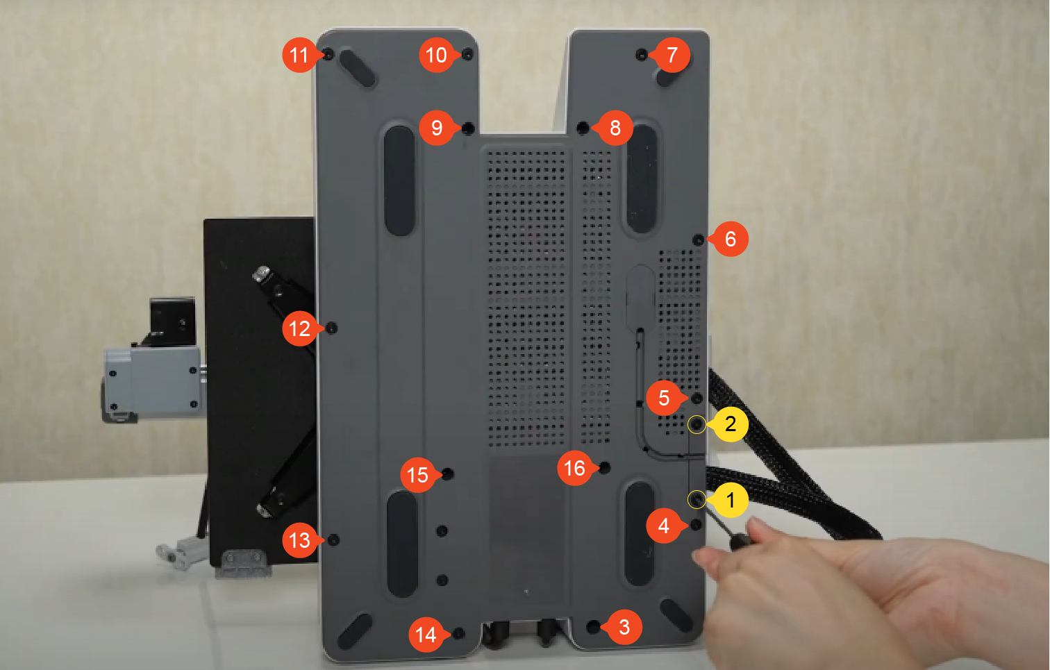
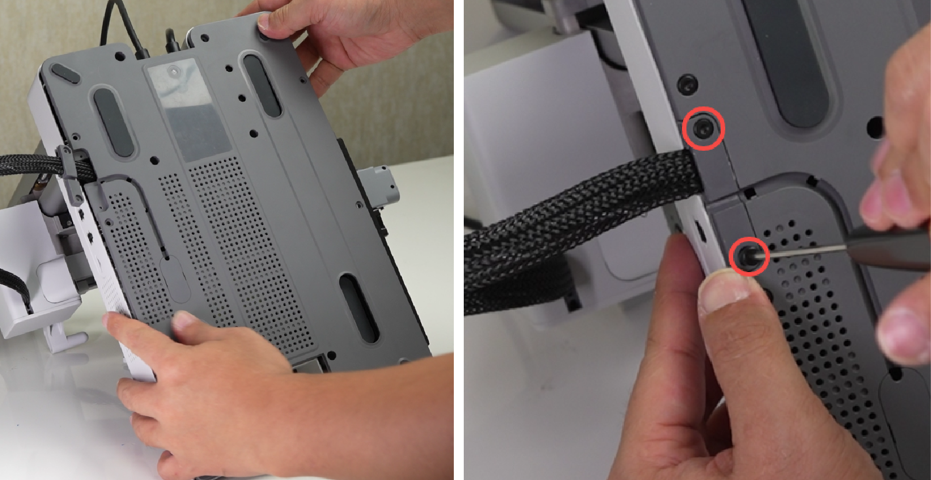
¶ Step 1: Remove the baseplate
Tilt the printer backward until the Z-axis pillars make contact with the table surface.
Use a H2.0 hex wrench to remove the 2 screws (BT2.6×8), then remove the 14 screws (BT3×8). Pull the nylon mesh to loosen the baseplate, and then remove the baseplate.
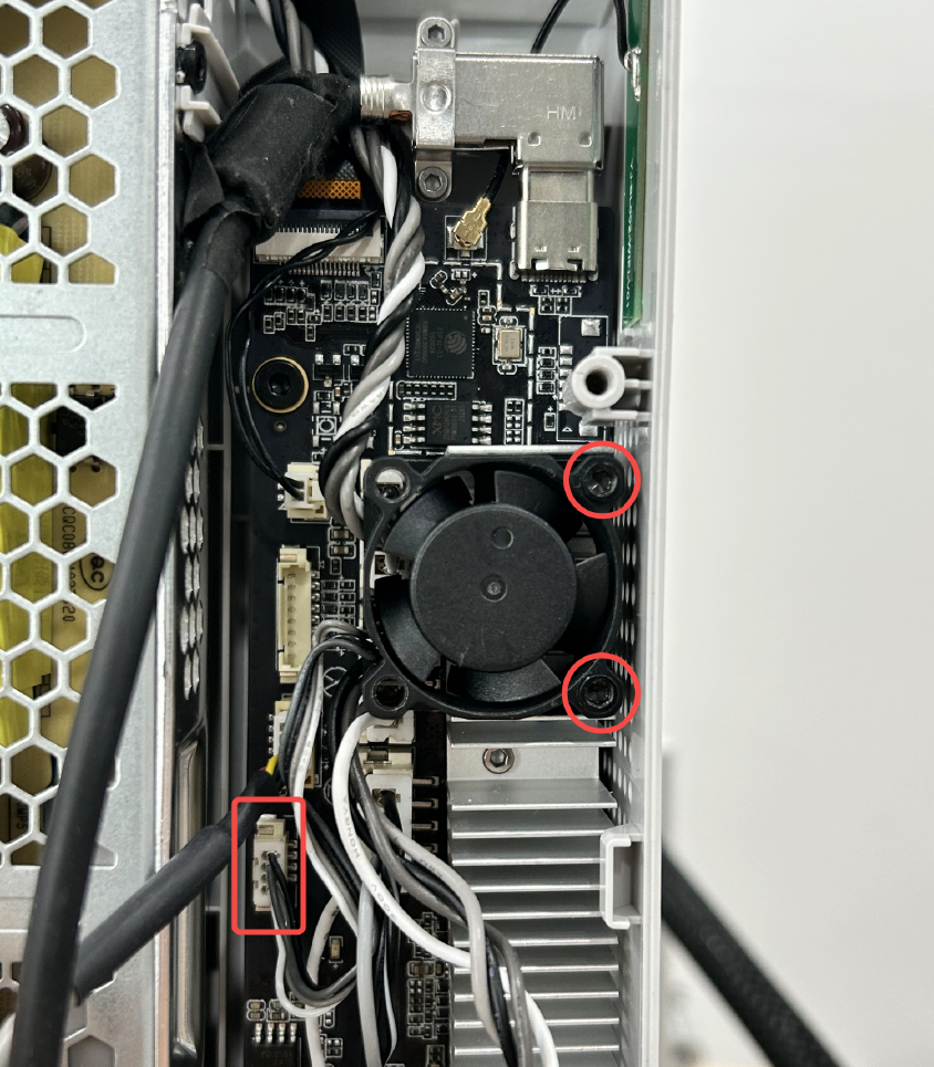
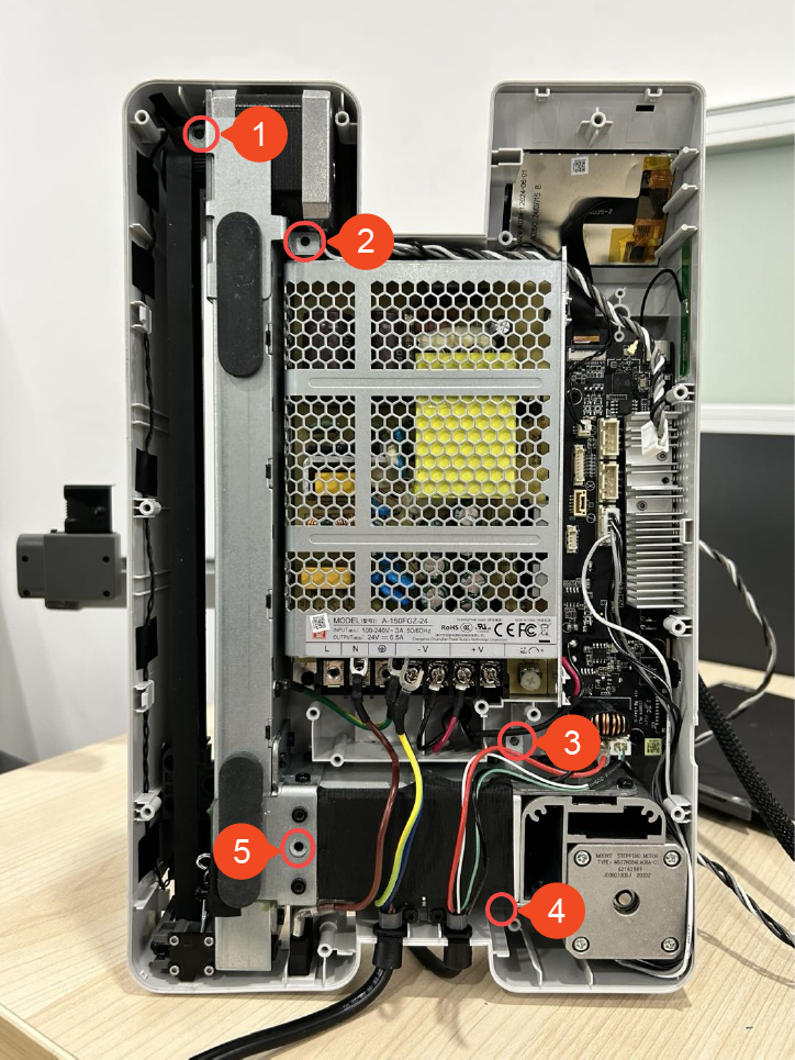
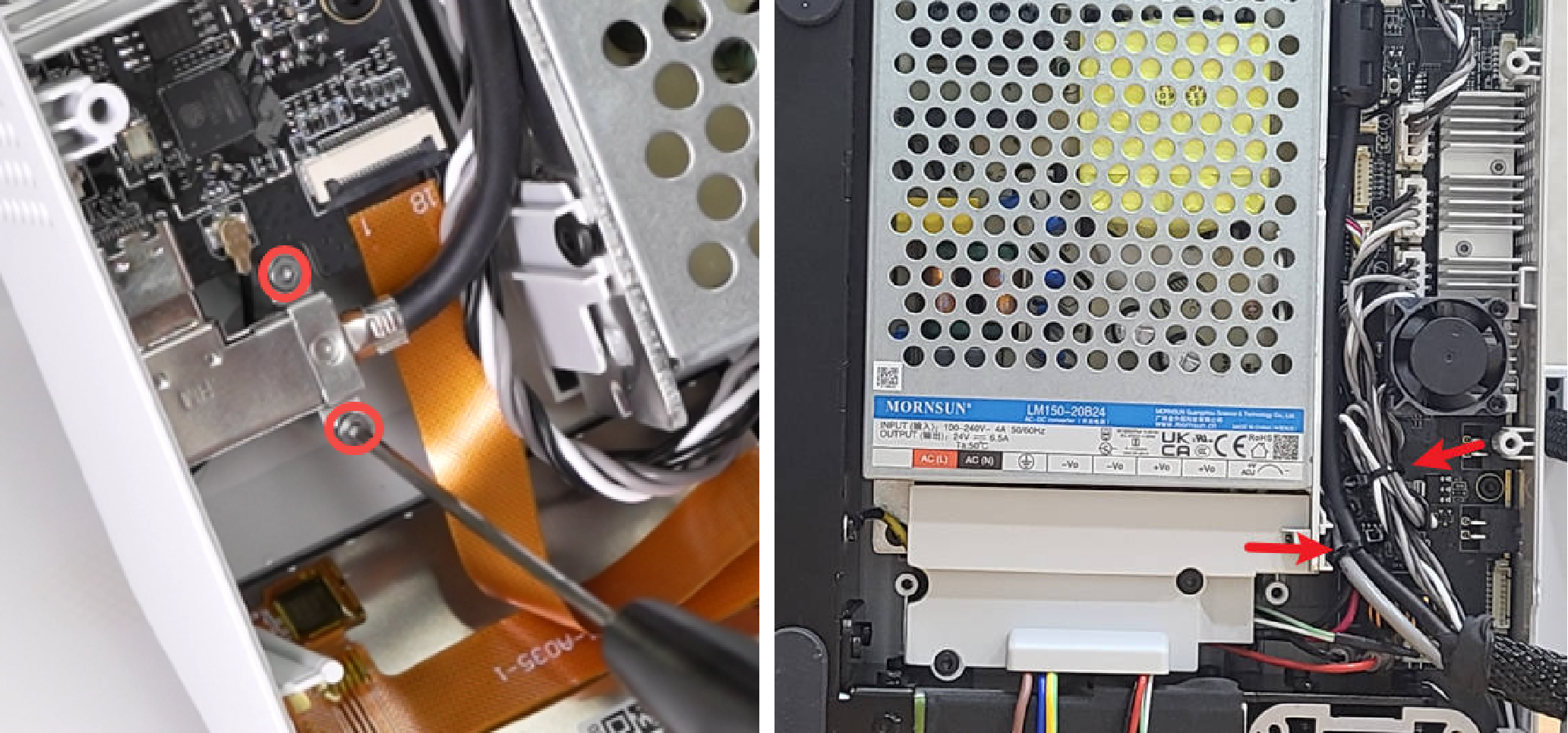
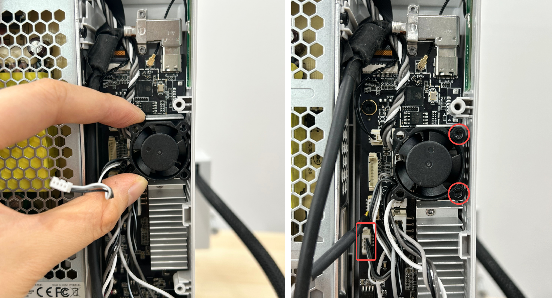
¶ Step 2: Remove the main board fan
Use the H2.0 hex wrench to remove 2 screws (MG2.5×15),and disconnect the main board fan cable.
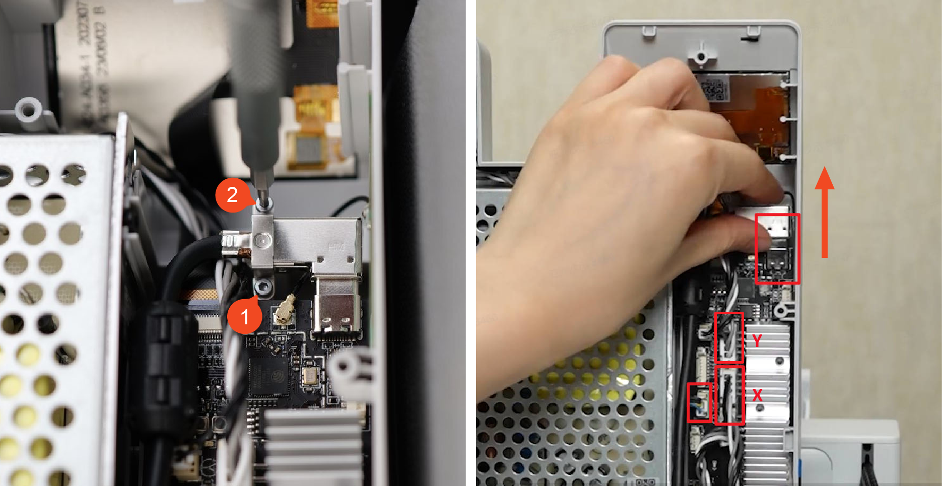
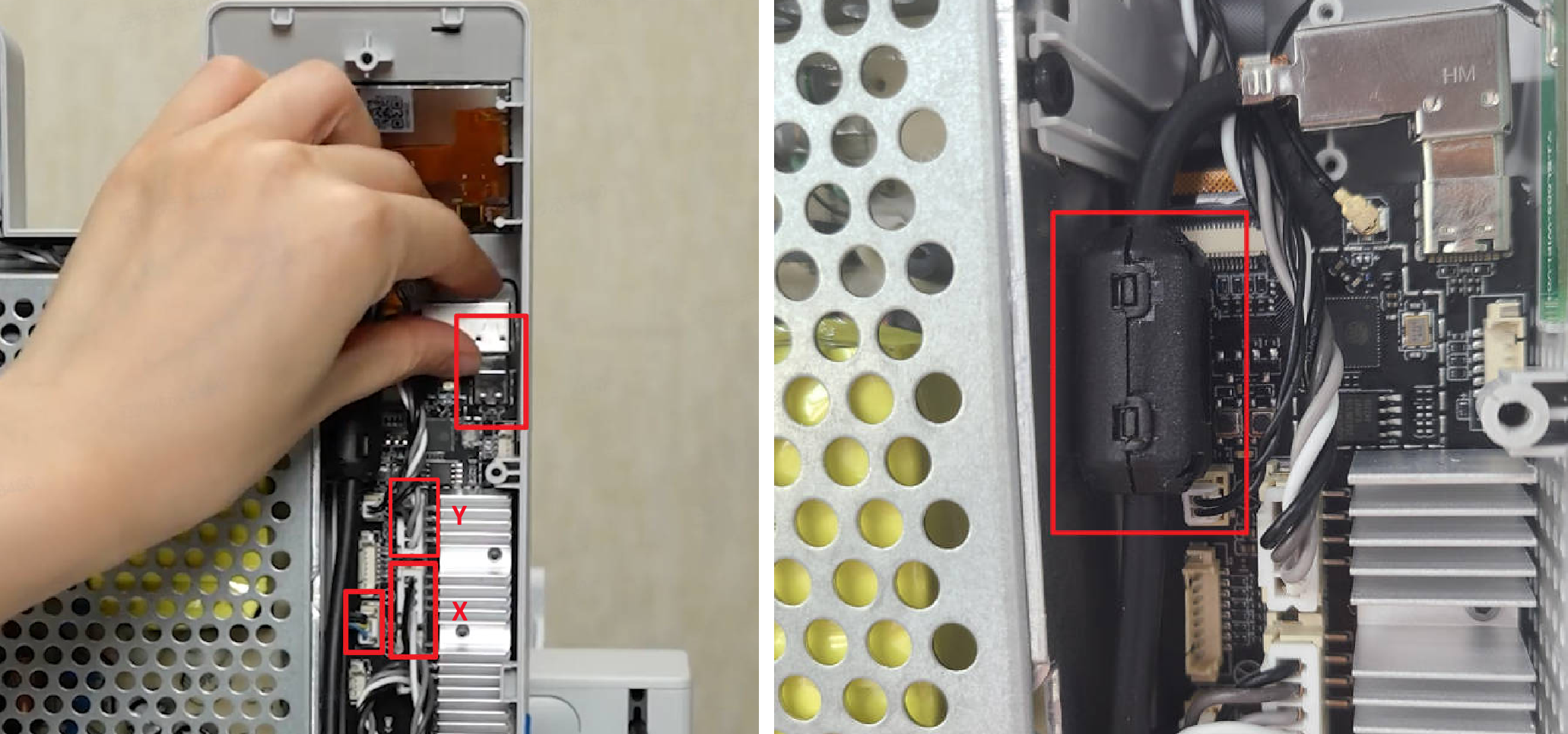
¶ Step 3: Disconnect main board cables
Remove the two screws (BT2×5) and plate. Disconnect the USB cable, Y motor cable, X motor cable, and camera cable from the mainboard. Please note that the camera cable has a locking mechanism — press to unlock before disconnecting. Gently move the nylon-sleeved cable to the side to avoid pulling or damaging the internal wiring during the operation.
¶ Step 4: Disconnect the power supply cables
Use an H2.0 hex wrench to remove 3 screws (BT3×8), remove the fireproof cover;
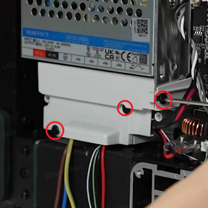
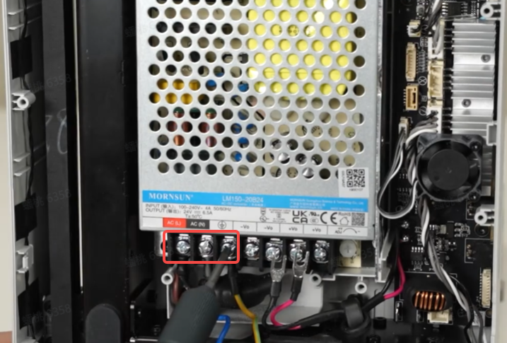
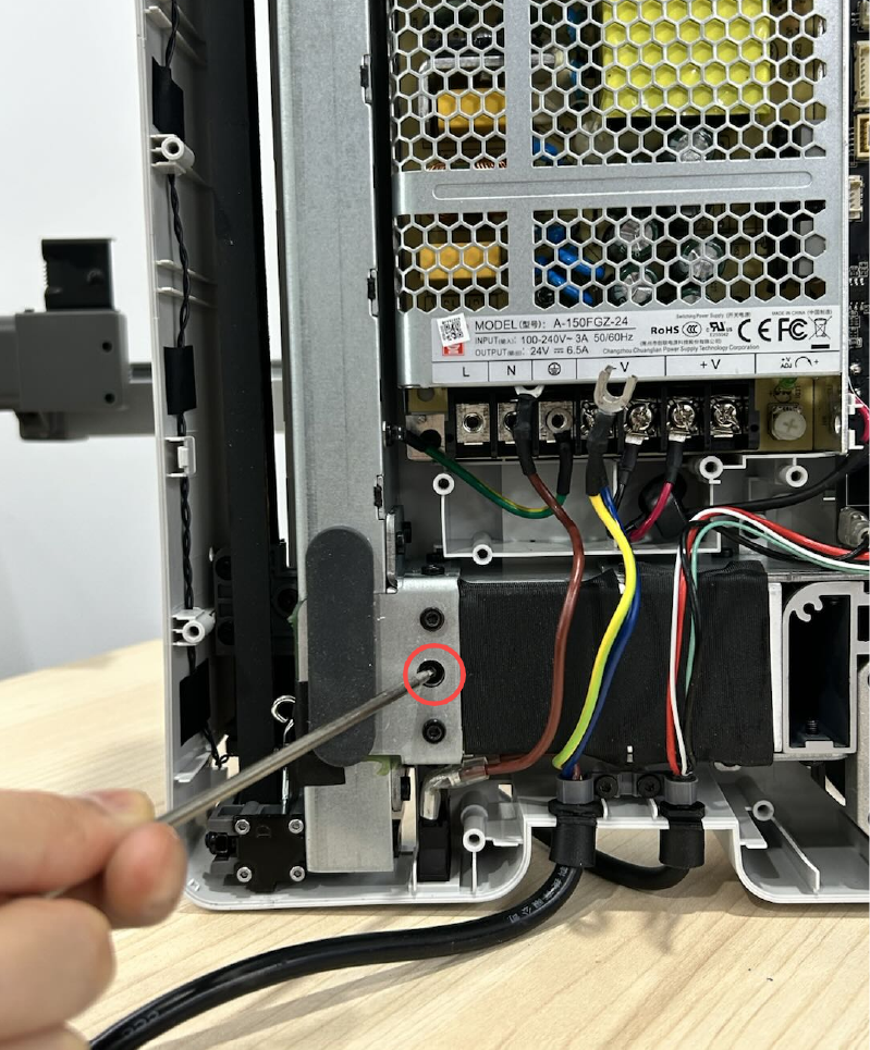
Use a Phillips screwdriver to loosen the 3 terminal screws and remove the printer power cable from the power supply.
¶ Step 5: Remove the heatbed
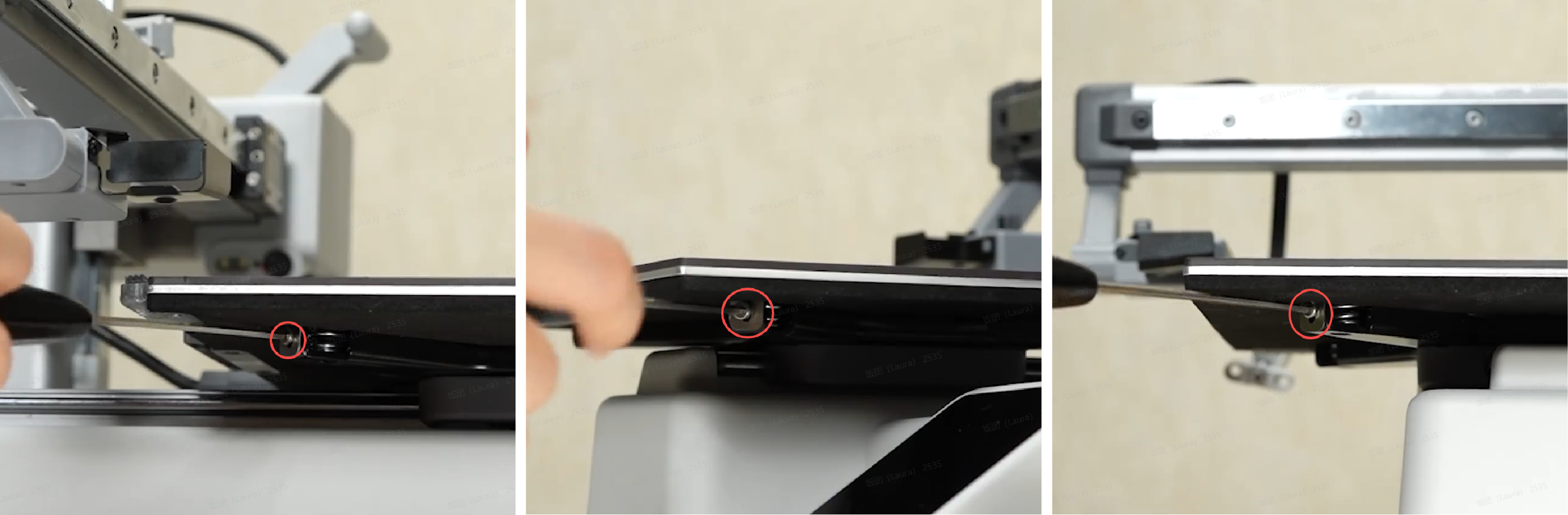
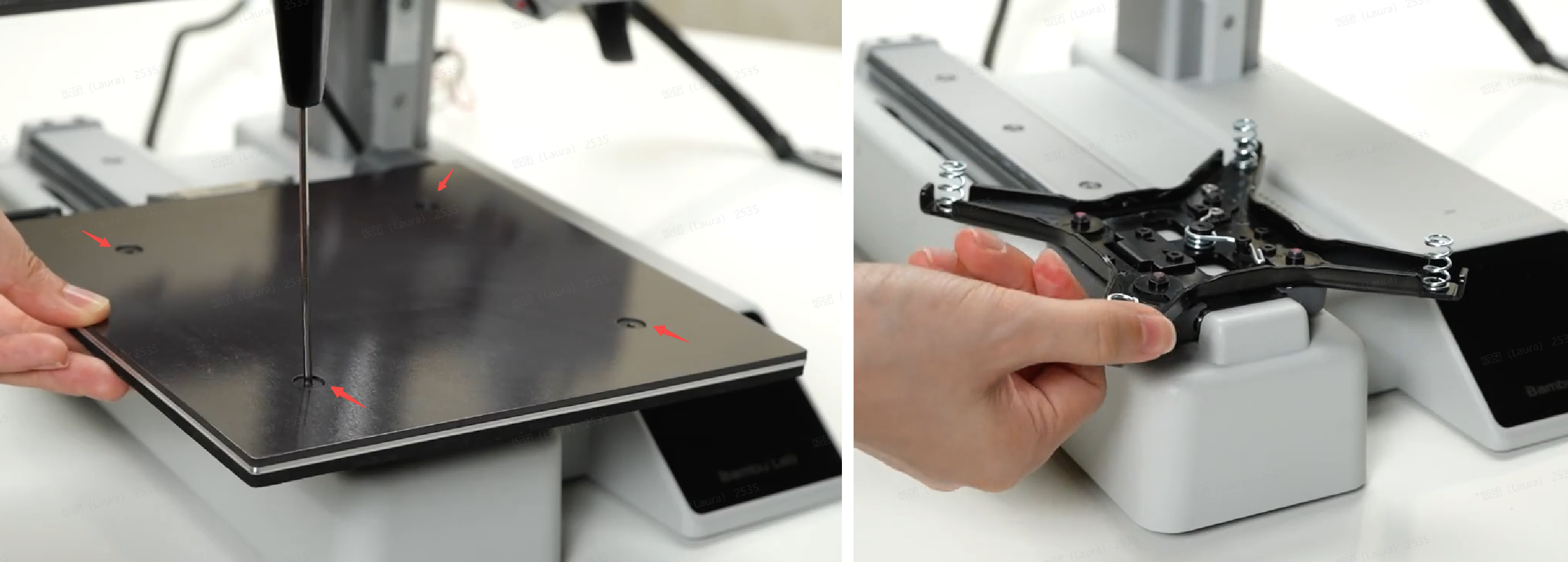
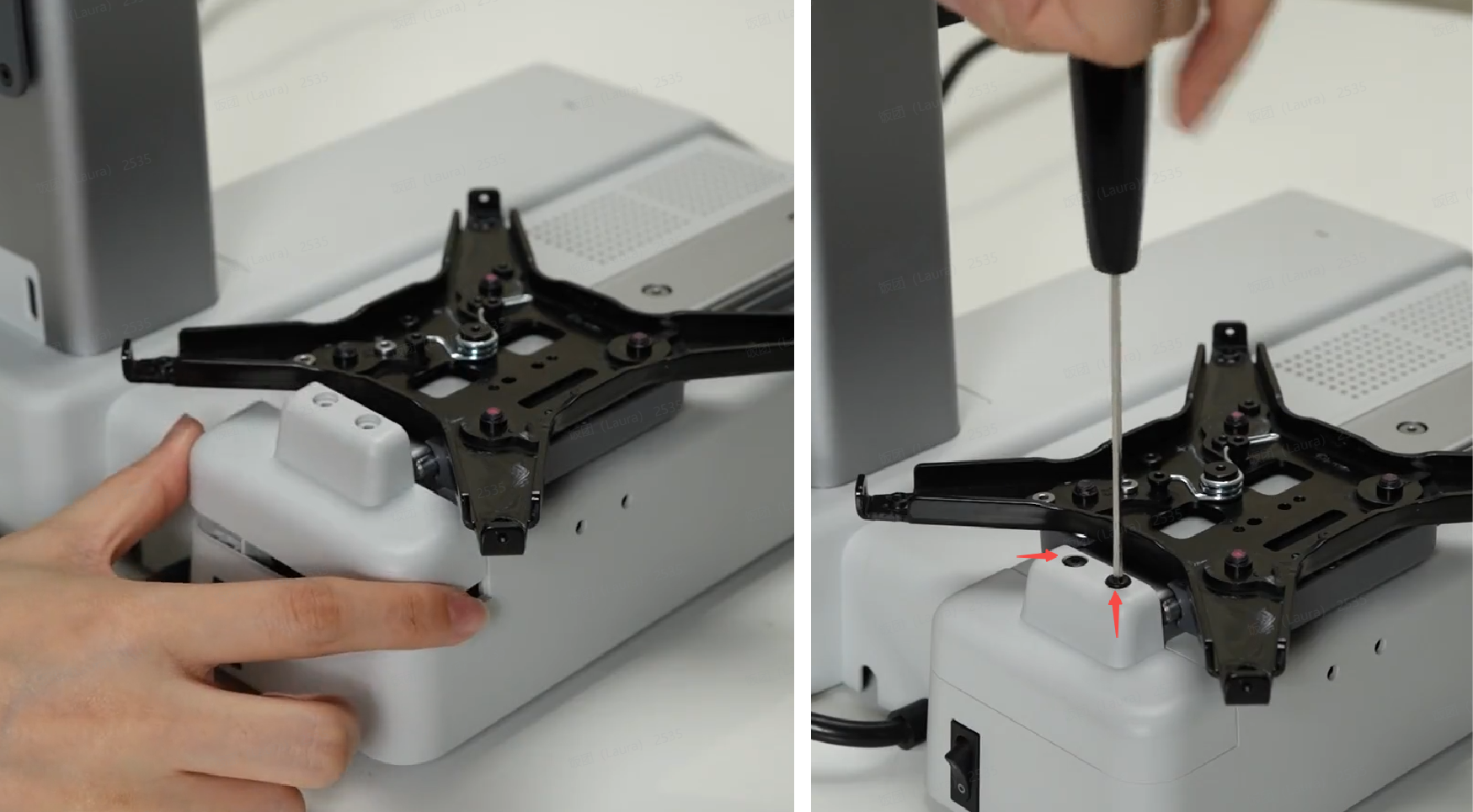
Place the printer upright and remove 3 screws (M2.5×5) that secure the heat bed;
Press down on the heat bed with your hand and remove 4 leveling screws (MG4×13). Take off the heat bed along with the adjustment springs. If the adjustment springs are fixed, removal is not necessary.
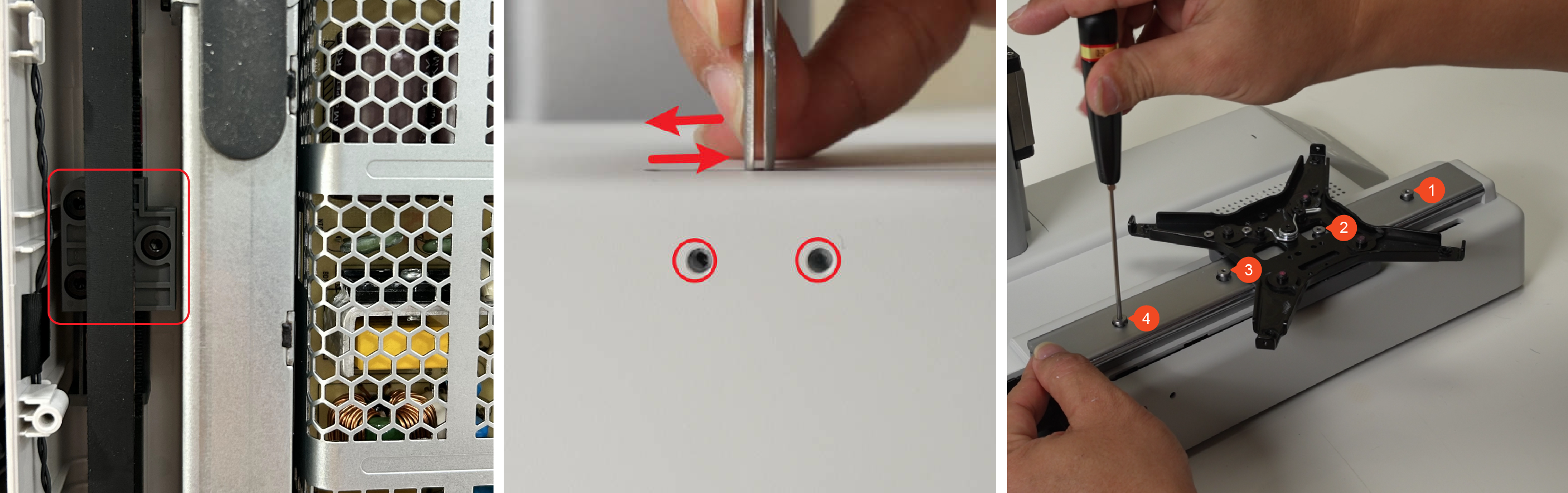
¶ Step 6: Remove the Y-axis linear rail
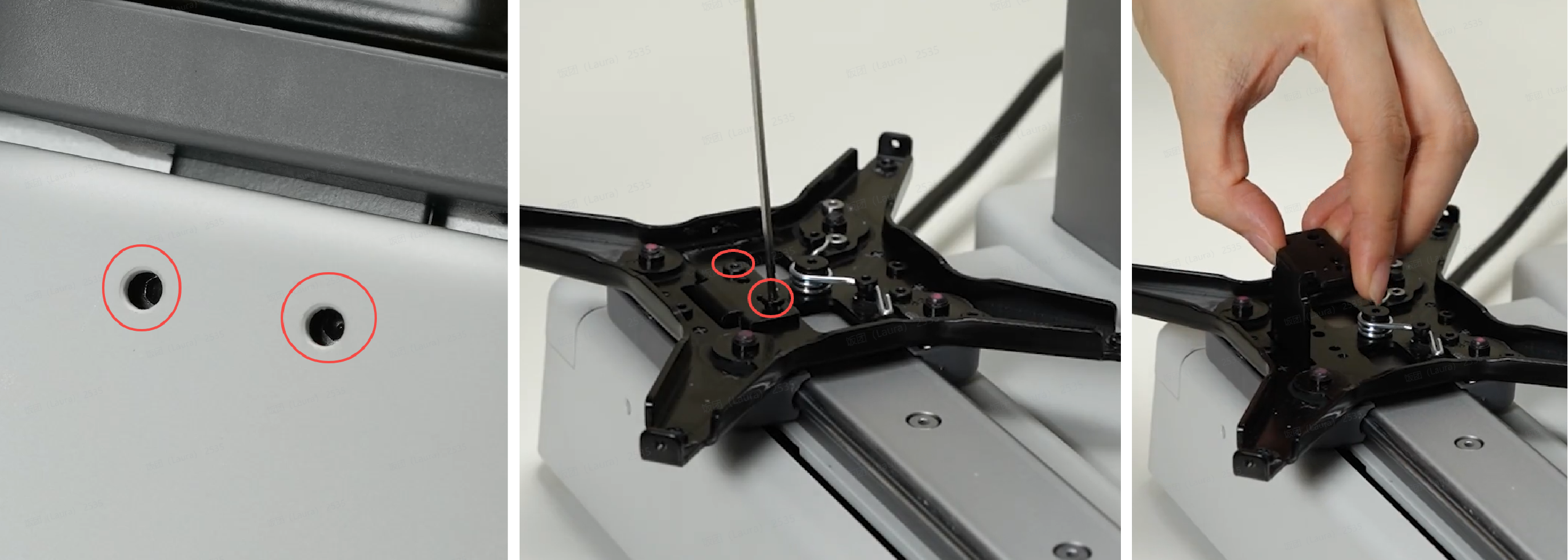
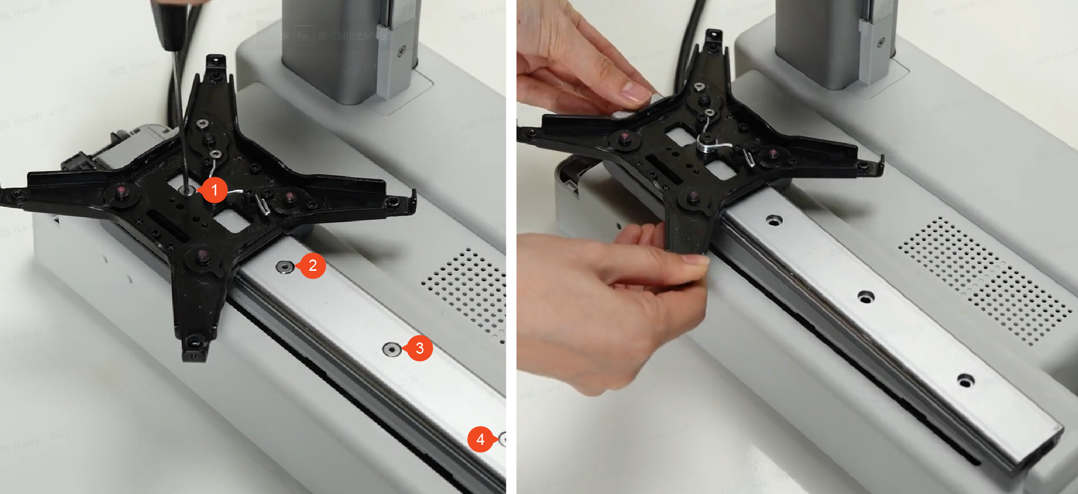
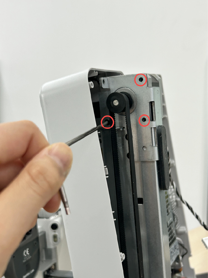
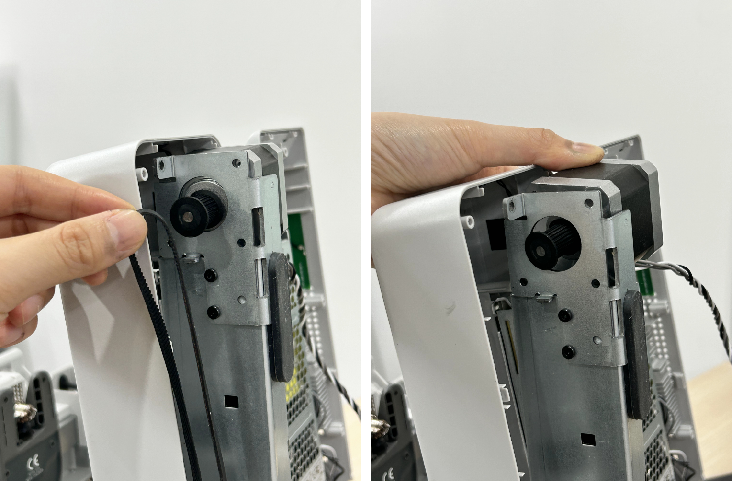
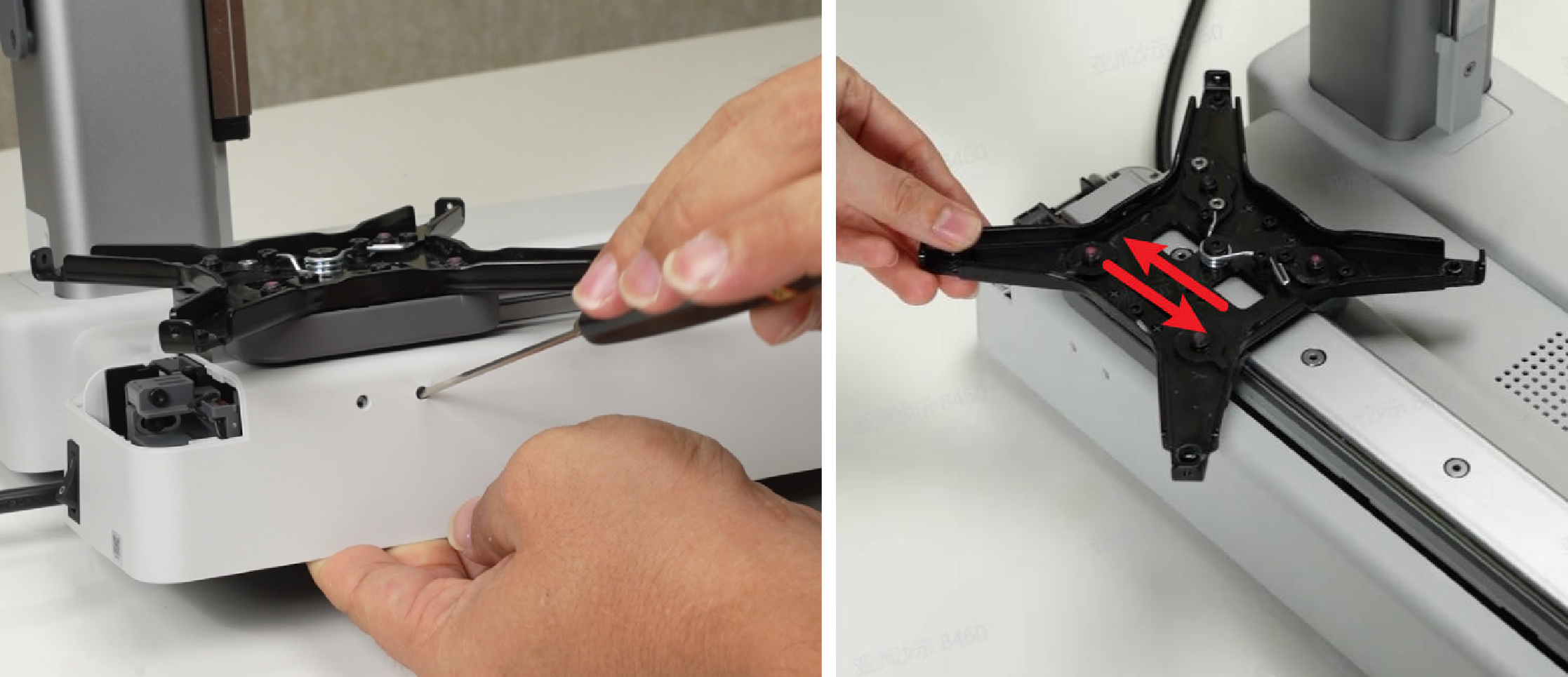
Push the heatbed bracket backward to expose the 2 screws on the connecting plate and loosen the screws completely, then remove the 2 screws (M3×4.5) on the pulley and take down the connecting plate;
Remove 2 (M2.5×18) and take off the Y-axis rear cover;
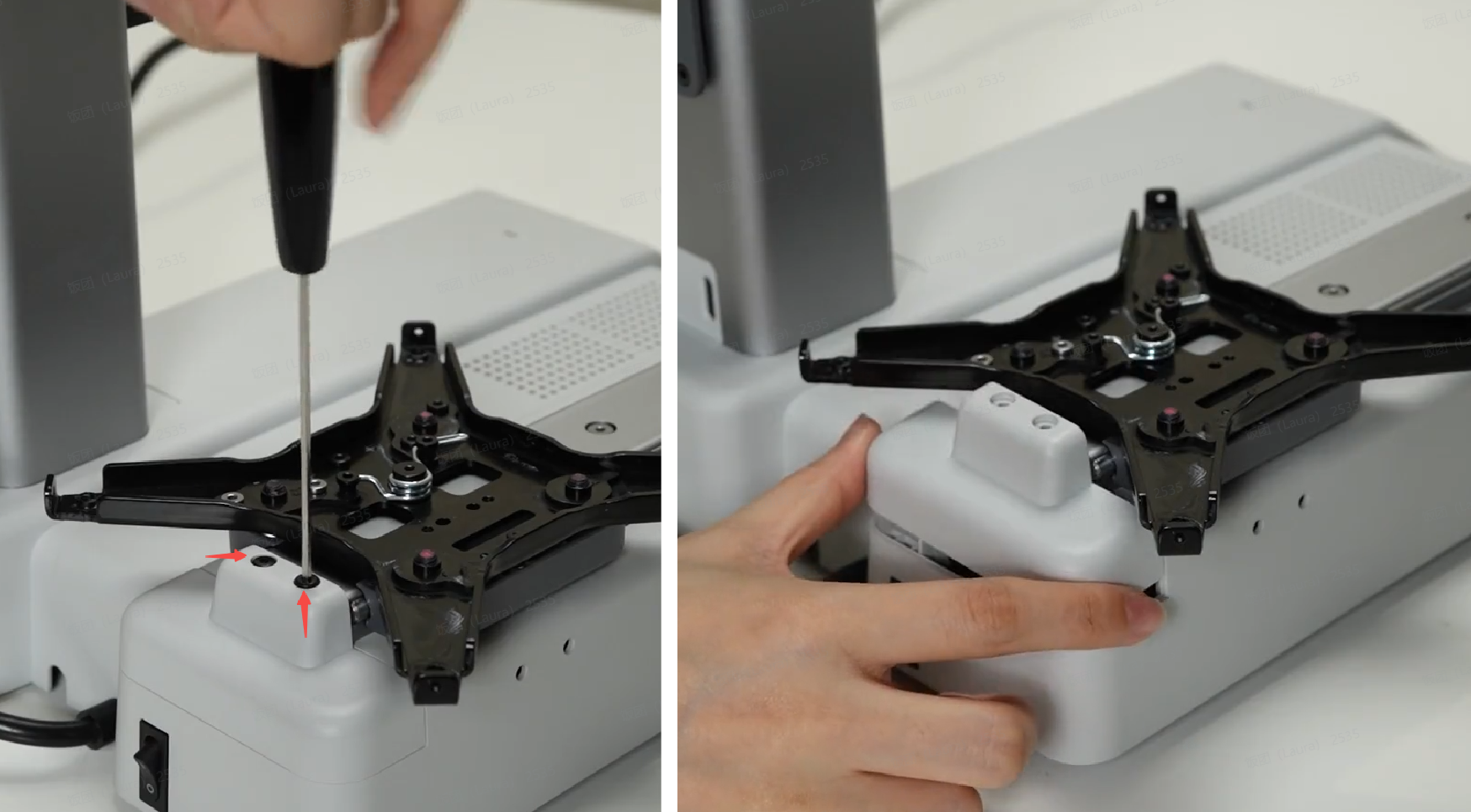
Remove 4 screws (M4×16) and remove the Y-axis linear rail. When removing the linear rail, please hold both the bracket and the linear rail to prevent slipping.
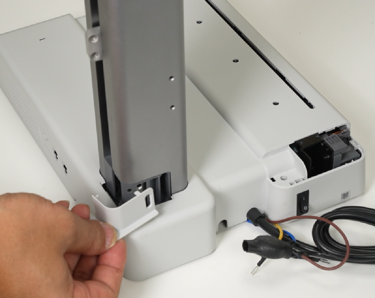
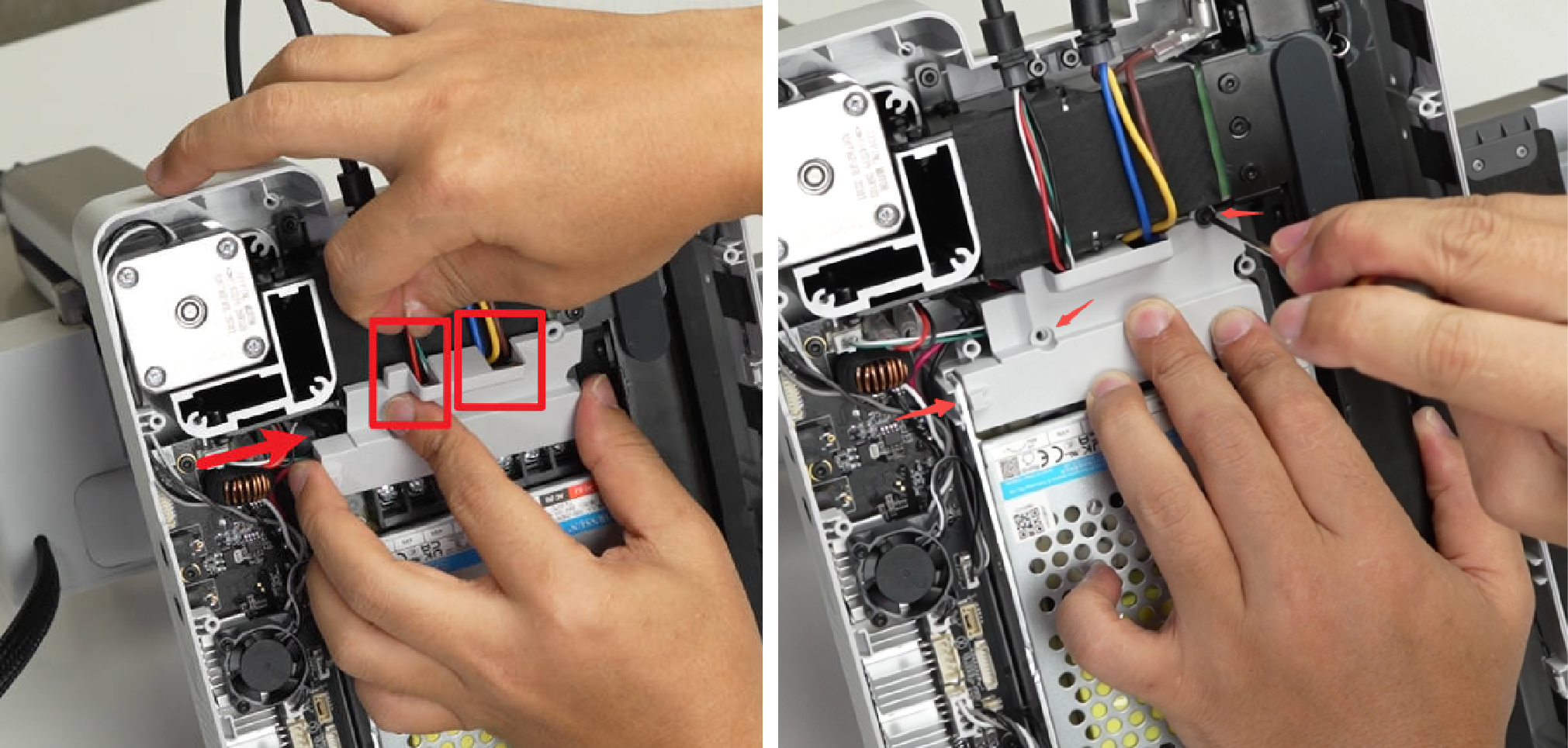
¶ Step 7: Loosen base housing
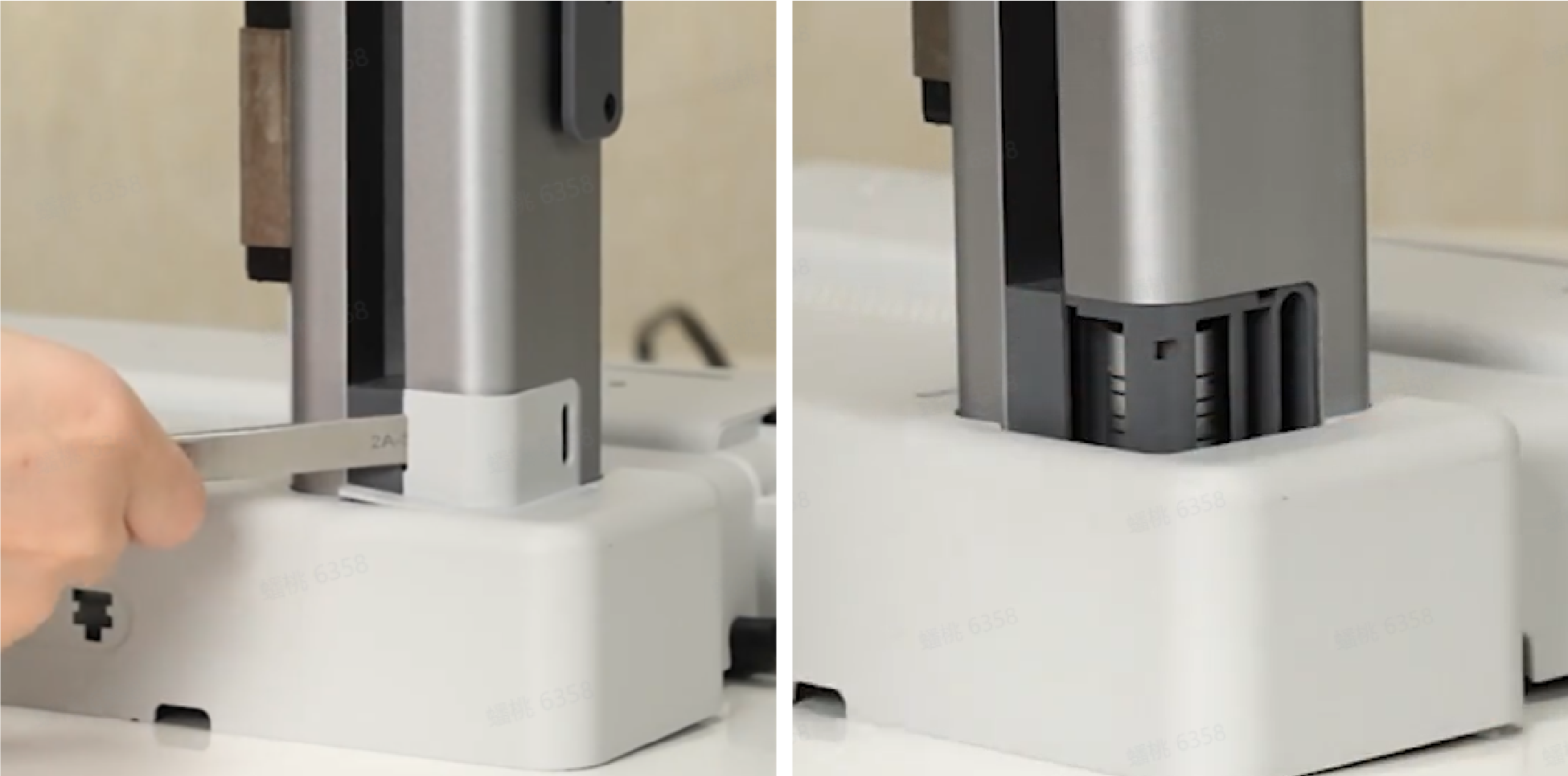
Remove the Z-axis trim cover with flat-tip tweezers;
Remove 4 screws (BT3×8) with H2.0 hex wrench;
Remove 1 screws (BTG3×45) with H2.0 hex wrench.
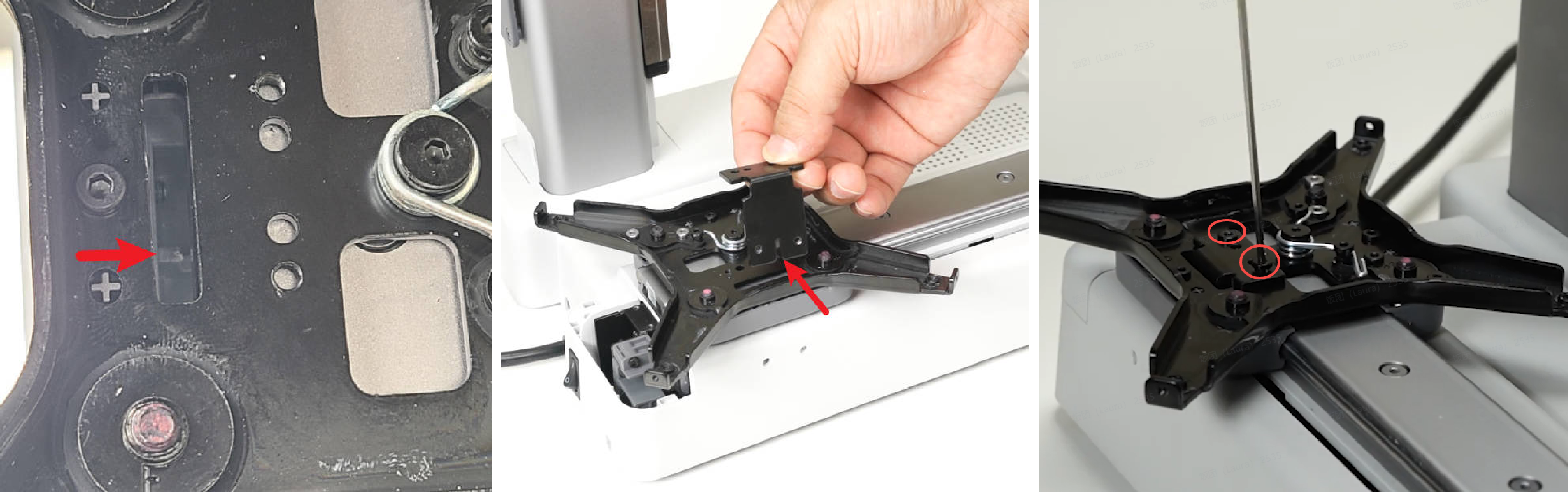
¶ Step 8: Remove the Y motor
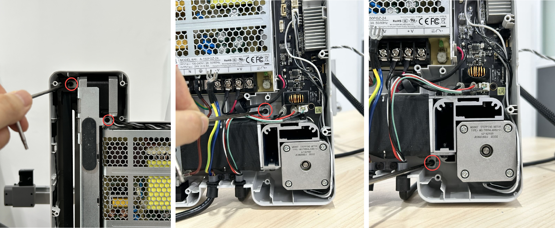
Gently move the base by hand to expose the Y motor. Remove the three screws (M3×6) with an H2.0 hex wrench;
Remove the belt and take out the Y motor.
¶ Assemble Y motor
¶ Step 1: Install the Y motor
Thread the Y motor through the motor mounting bracket, ensuring the cable orientation is correct. Hang the drive pulley onto the Y belt and then install it in place. Secure the Y motor in place by tightening three screws (M3×6).
¶ Step 2: Secure base housing
Insert and tighten 1 screw (BTG3×45) and 4 screws (BT3×8) to secure the base housing;
Install the Z-axis trim cover.
¶ Step 3: Install the Y-axis linear rail
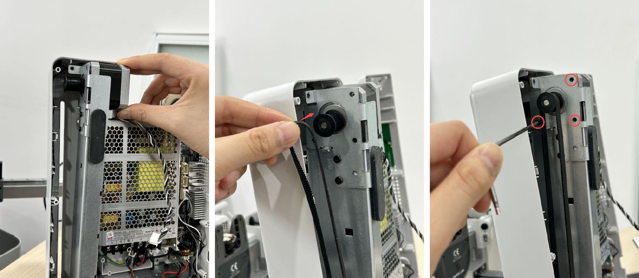
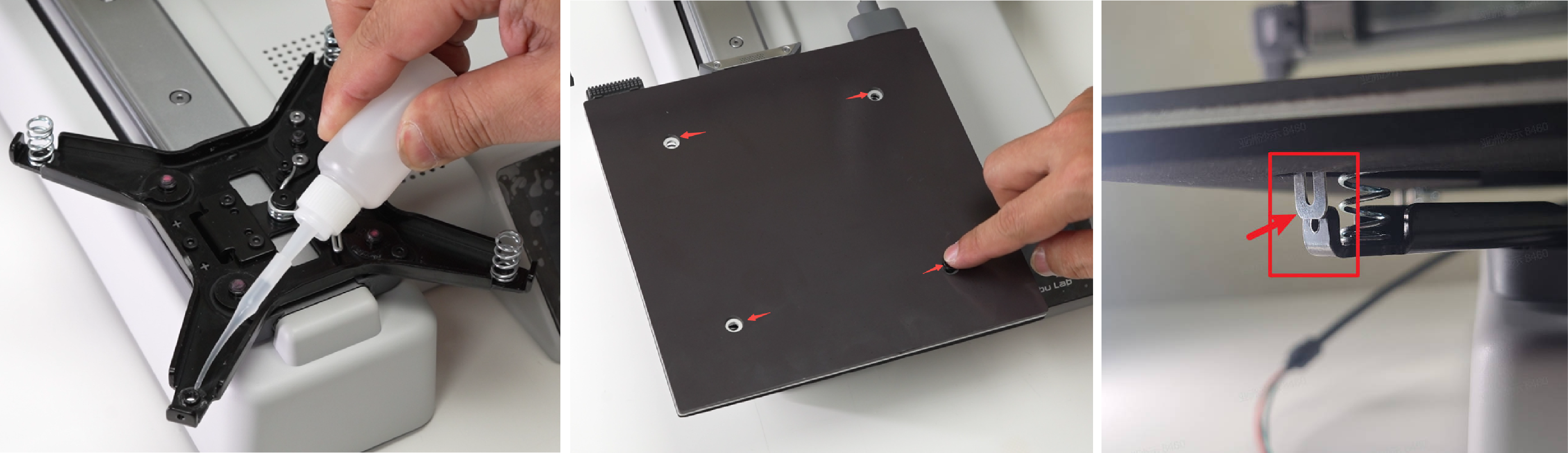
Use tweezers to move the Y belt pressing block (the component shown in the box from the bottom view) to expose the 2 screws. Confirm the installation direction according to the installation position of the connecting plate, place the Y-axis linear rail on the base, align the screw holes, put in 4 screws (M4×16), and lock them alternately;
Move the heatbed bracket to expose the Y-axis belt block, then install the connecting plate, confirm that it is in place, and lock 2 screws (M3×4.5) to fix the connecting plate;
Then tighten the 2 screws through the base, move the heatbed bracket, and confirm that the heatbed bracket can drive the Y belt to move smoothly.
Install the Y-axis rear cover, and lock in 2 screws (M2.5×18).
¶ Step 4: Install the heatbed
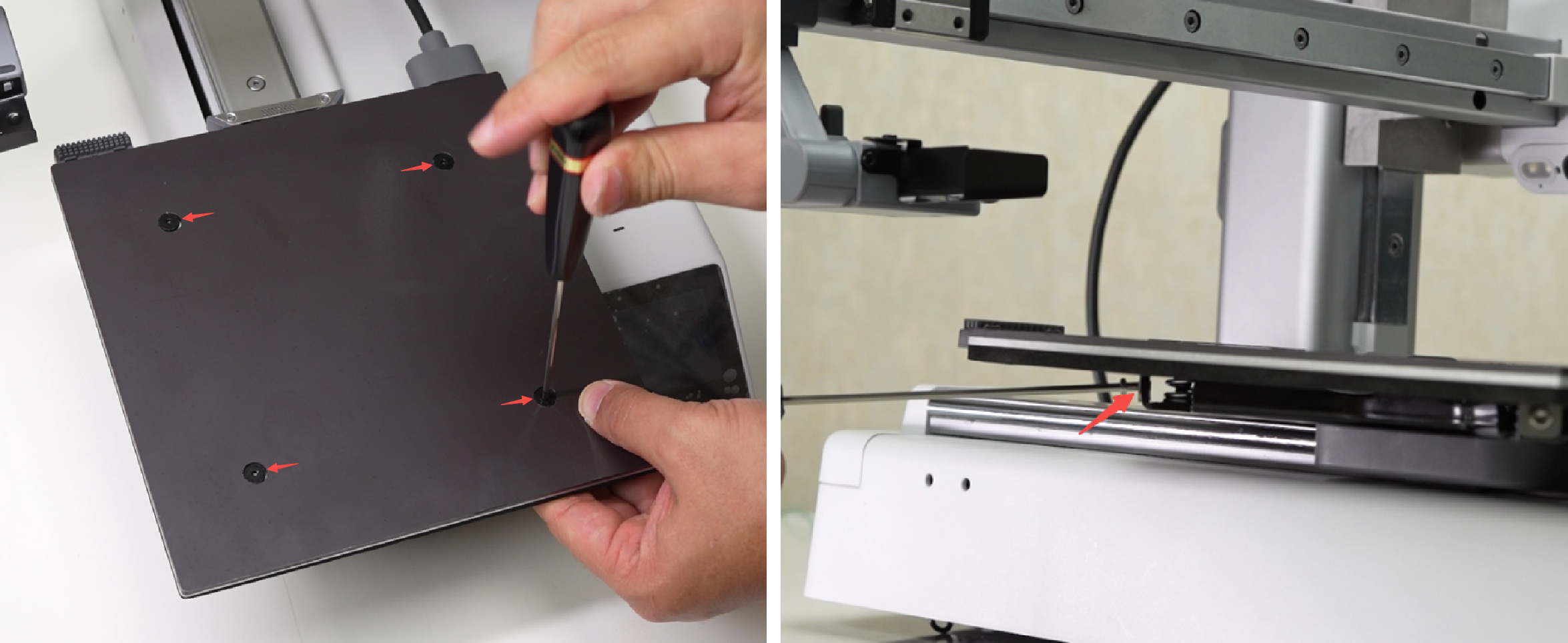
Pre-fix the four springs to the corresponding positions with glue, align the spring positions, place the heatbed, and confirm from the bottom of the heatbed that the three fixing pieces on the heatbed are all on the outside of the heatbed bracket;
Insert 4 leveling screws (MG4×13) and compress the leveling spring of the heatbed by hand so that the leveling screws can be locked. After all are locked, loosen the 4 leveling screws by 1 turn; install 3 heatbed secure screws (M2.5×5), but do not tighten them. These 3 screws need to be tightened after completing the manual leveling of the heatbed.
¶ Step 5: Connect power supply cables
Connect the power cables to the input terminals, with the brown wire connected to L, blue wire connected to N, and two yellow-green wires connected to the ground, and then tighten the 3 screws;
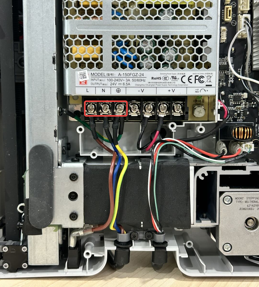
Arrange the heatbed cables and power cable, install the fireproof cover, confirm that the cables are not pressed, and then lock in the 3 screws (BT3×8).
¶ Step 6: Connect main board cables
Connect the Y motor cable, X motor cable and camera cable to the mainboard. Then connect the USB cable. After confirming the location of the ferrite cores, lock the pressing piece with 2 screws (BT2×5). Arrange the cables and tie them with small zip ties.
¶ Step 7: Install the main board fan
Install the main board fan with the cable facing left. Lock it with two screws (MG2.5×15), and then connect the main board fan cable.
¶ Step 8: Install the Baseplate
Install the baseplate, align the position, and lock in 14 screws (BT3×8) to fix it; then install the cable clamp, lock in 2 screws (BT2.6×8) to fix it; place the printer upright.
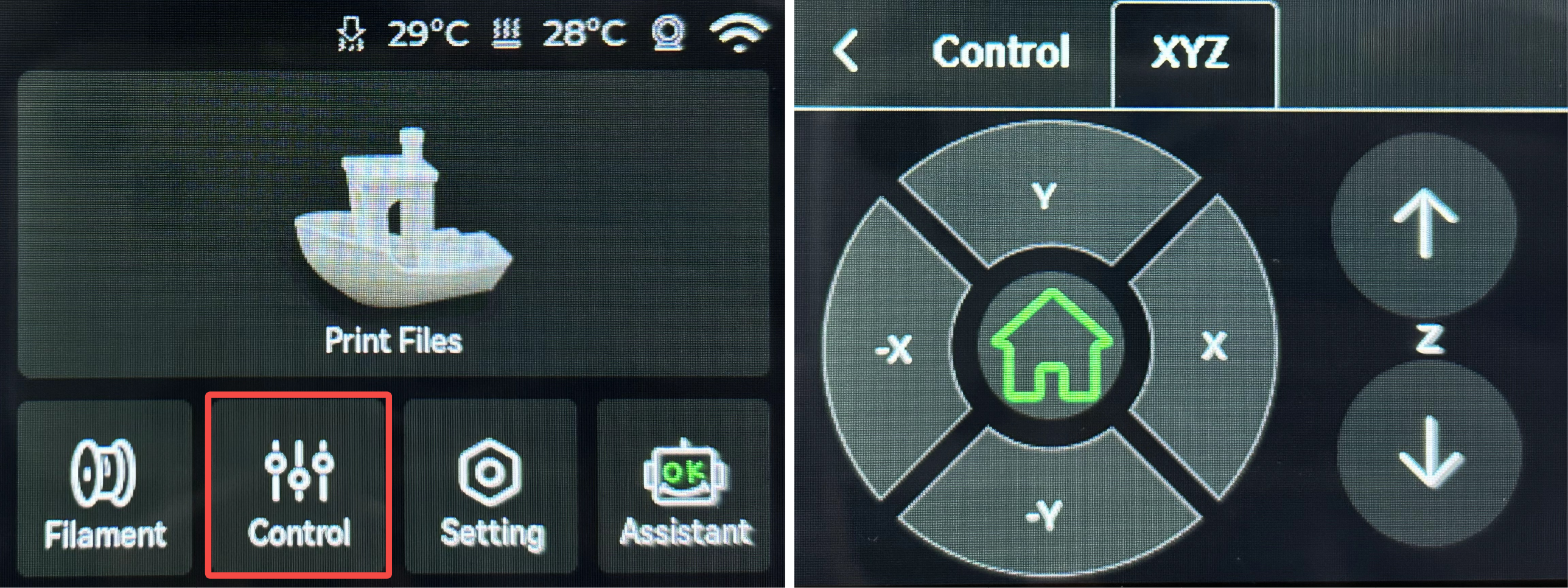
¶ Functionality Verification and Calibration Step
After completing all the assembly steps above, power on the printer, enter the control interface, and click the "-Y" or "Y" button on the screen to move the Y-axis and confirm whether the Y motor is functioning properly.
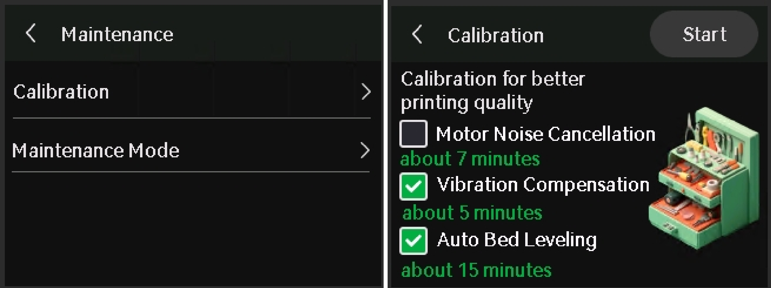
In the Calibration screen, select only Vibration Compensation and Auto Bed Leveling, and then tap Start. After completing calibration, tighten the three heatbed mounting screws.
The calibration will confirm the printer is running as expected.
¶ End Notes
We hope the detailed guide provided has been helpful and informative.
To ensure a safe and effective execution, if you have any concerns or questions about the process described in this article, we recommend submitting a technical ticket regarding your issue.
Please include a picture or video illustrating the problem, as well as any additional information related to your inquiry.