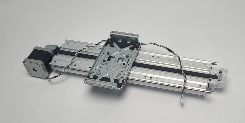
¶ Y-axis Linear Guide Assembly
Hereinafter, we will present the detailed steps for replacing the Y-axis component of A1.
¶ Applicable models of printers
Bambu Lab A1
¶ When to use?
- Abnormal noise and sluggishness on the Y-axis
- Recommended by Bambu Lab customer support
¶ Tools and materials needed
- New Y-axis Linear Guide Assembly
- H2.0 hex wrench
- 25 minutes
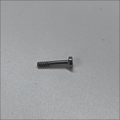
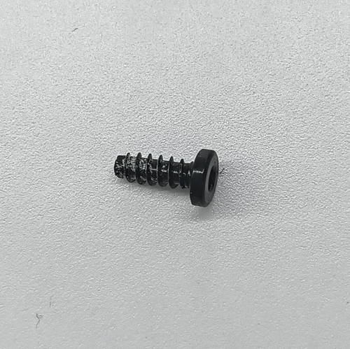
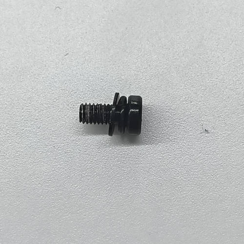
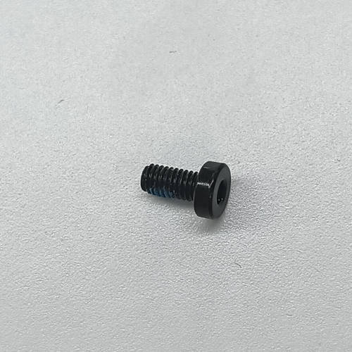
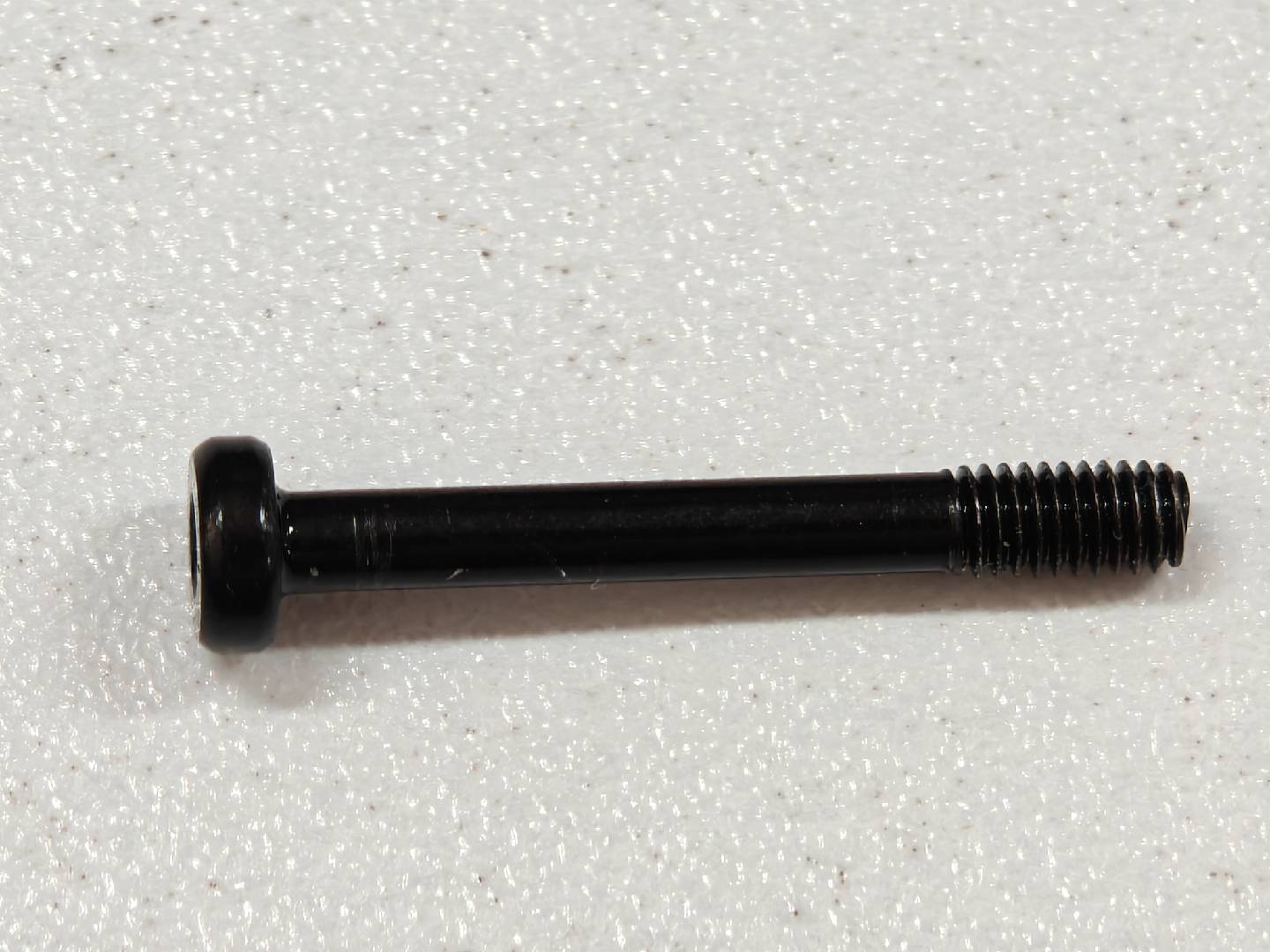
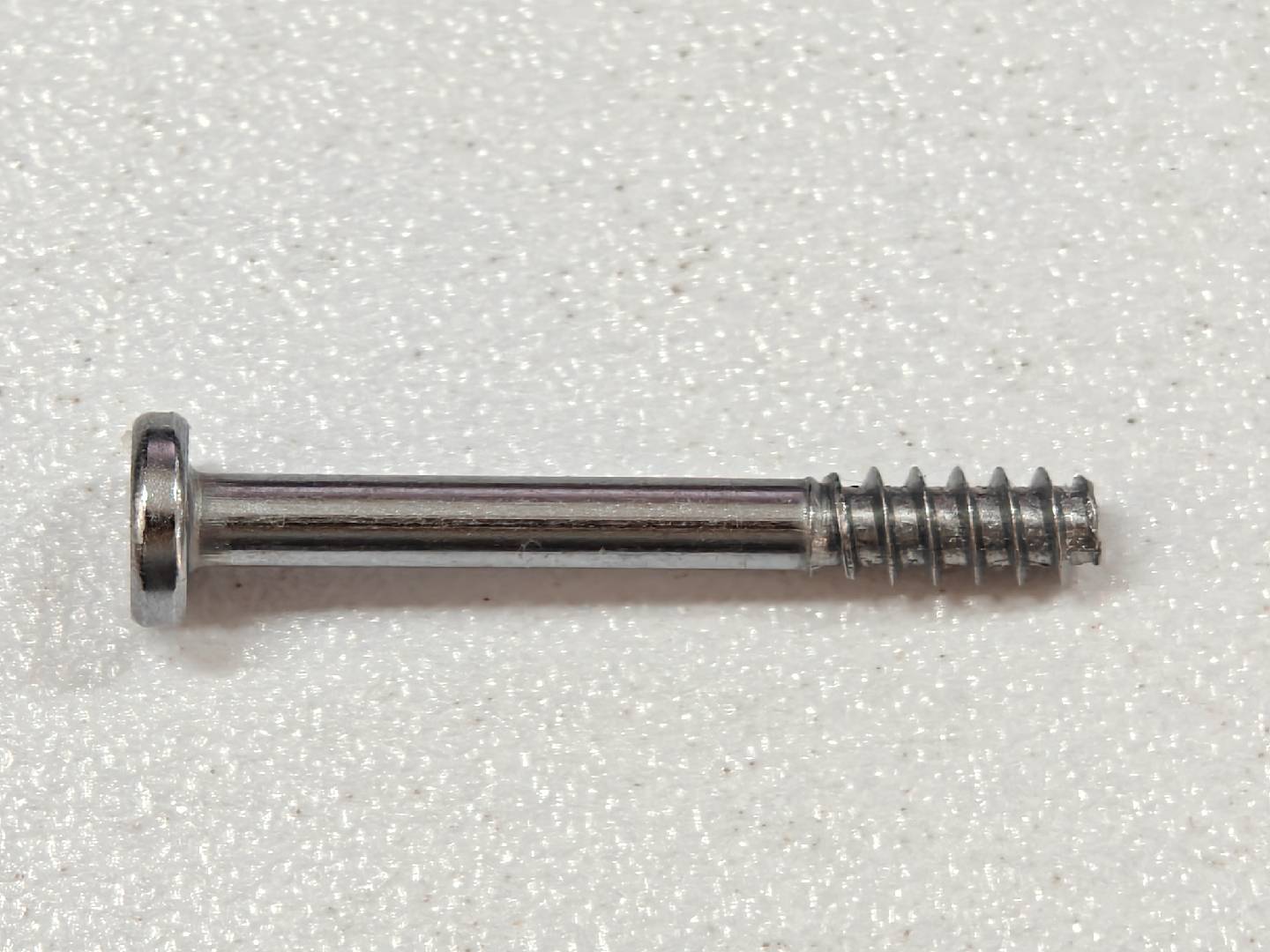
¶ List of screws
|
|
|
|
|
|
¶ Safety Warning
It's crucial to power off the printer before conducting any maintenance work, including work on the printer's electronics and tool head wires. Performing tasks with the printer on can result in a short circuit, leading to electronic damage and safety hazards.
During maintenance or troubleshooting, you may need to disassemble parts, including the hotend. This exposes wires and electrical components that could short circuit if they contact each other, other metal, or electronic components while the printer is still on. This can result in damage to the printer's electronics and additional issues.
Therefore, it's crucial to turn off the printer and disconnect it from the power source before conducting any maintenance. This prevents short circuits or damage to the printer's electronics, ensuring safe and effective maintenance. For any concerns or questions about following this guide, open a new ticket in our Support Page and we will do our best to respond promptly and provide the assistance you need.
¶ Remove the old Y-axis Linear Guide Assembly
¶ 1.Place the printer on its front
For easy access to the bottom section of the A1, you need to place the printer on the front.
Start by flipping the screen on its side, then gently place the printer on its front, as shown in the image below.
Use a box of filament to keep the top side raised to avoid putting pressure on the extruder and the screen.
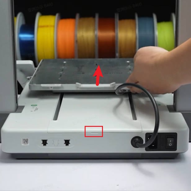
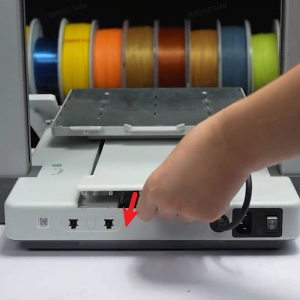
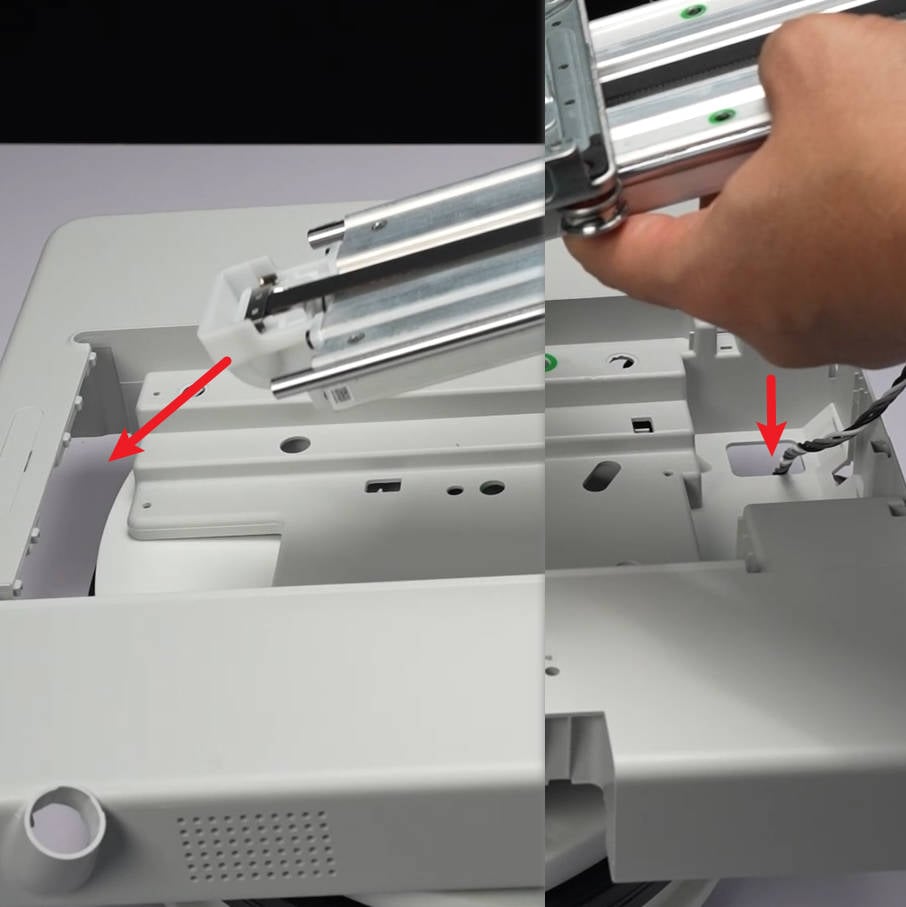
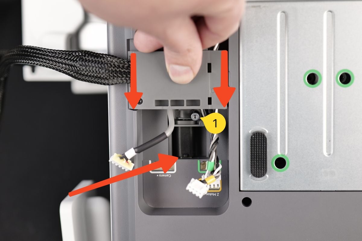
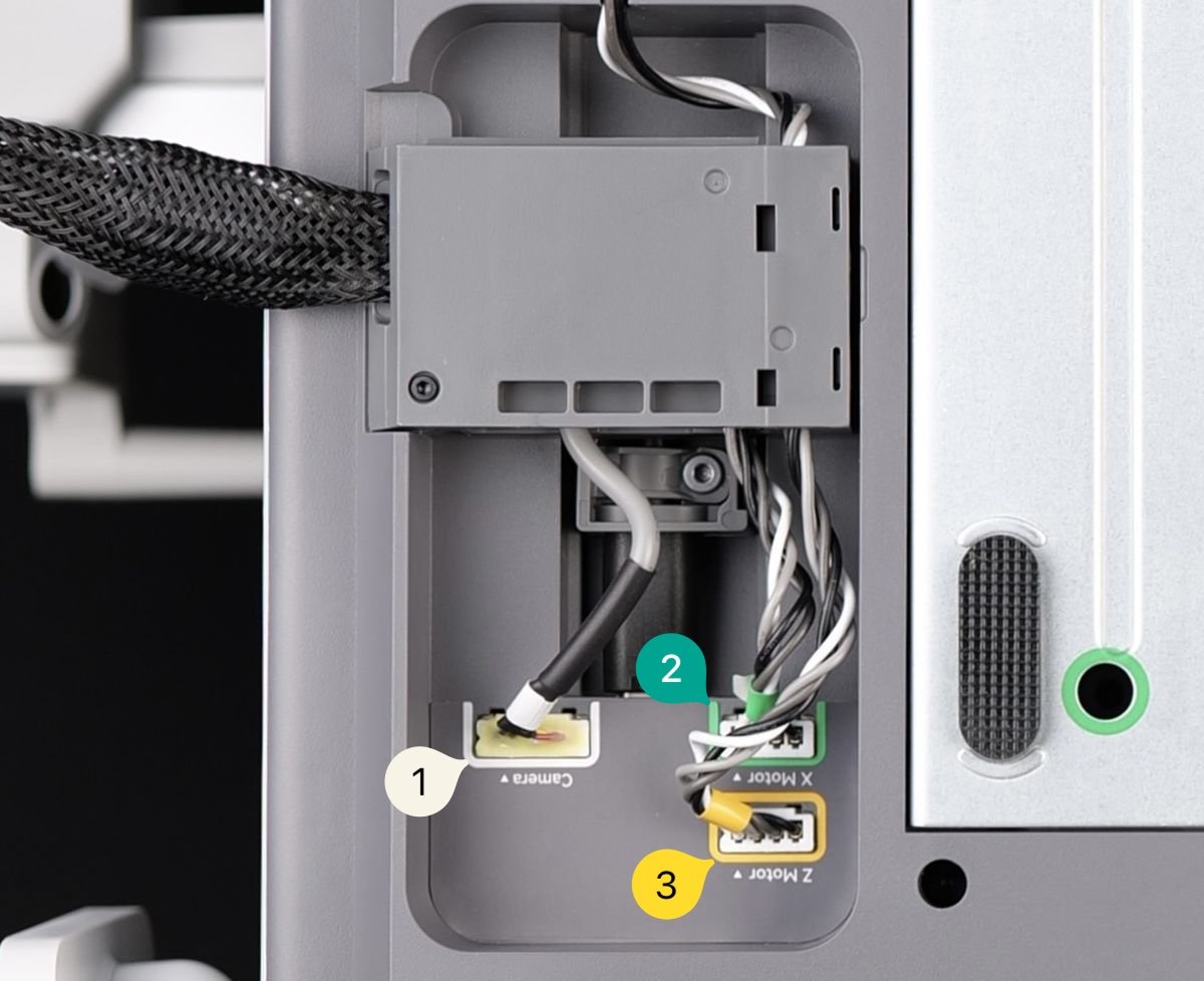
¶ 2.Disconnect the cable and remove the cable bracket
Loosen the yellow-marked screws without completely removing them. After removing the 1st, 2nd and 3rd cables, which are the camera, Z-axis motor and X-axis motor respectively, push up the cable bracket to disconnect the USB-C cable.
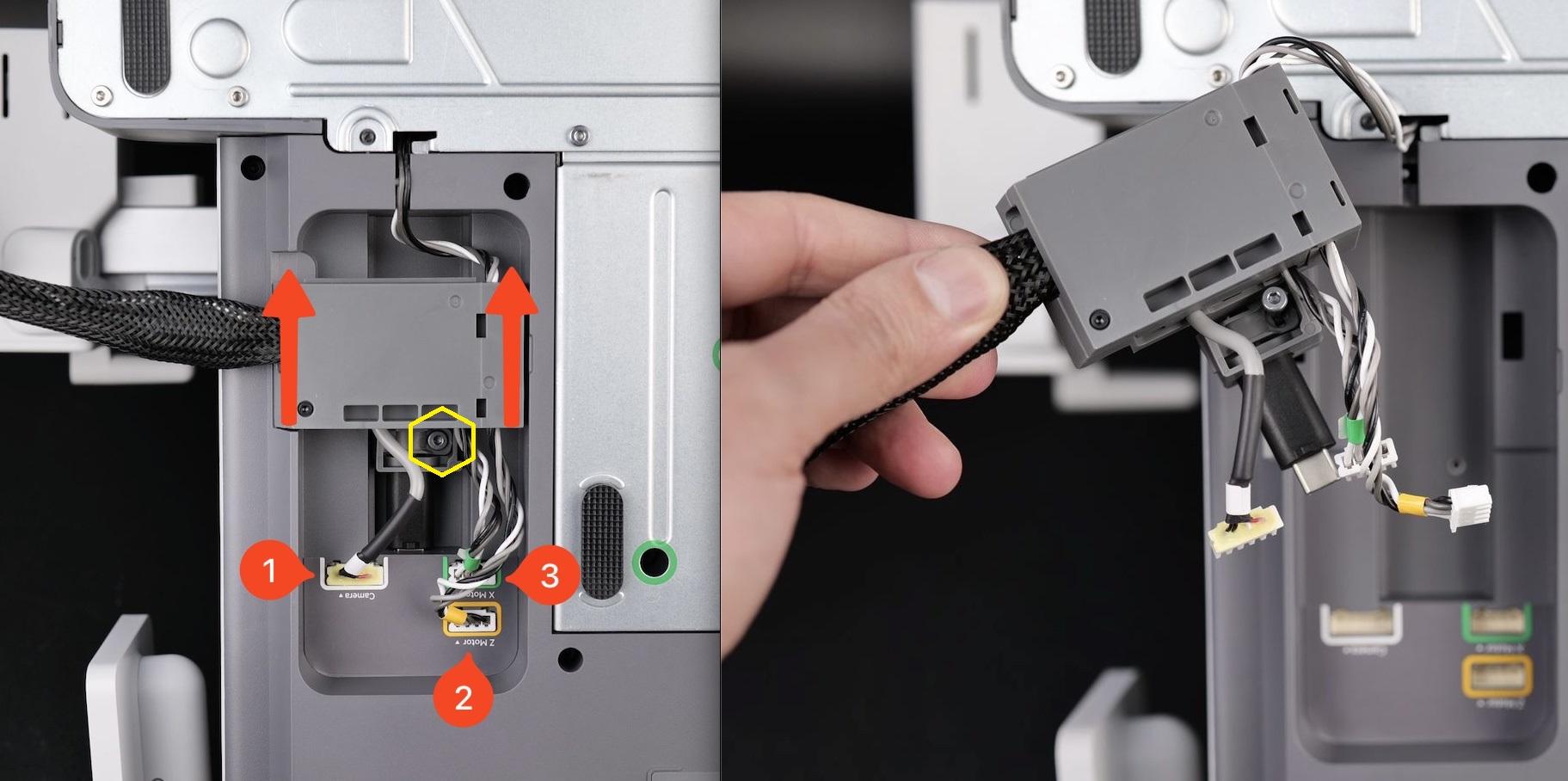
Note:If it is not easy to remove the cable bracket, you can completely remove the yellow-marked screws and try again.This screw is of model BT3-27.
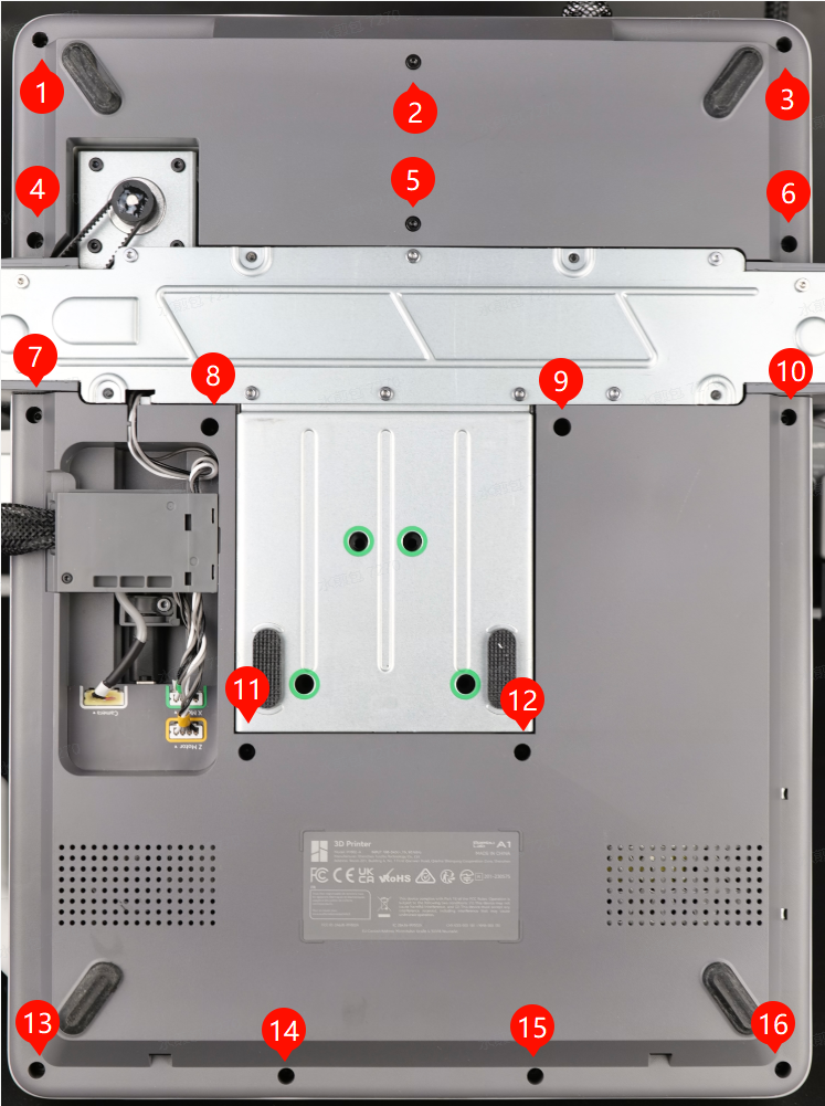
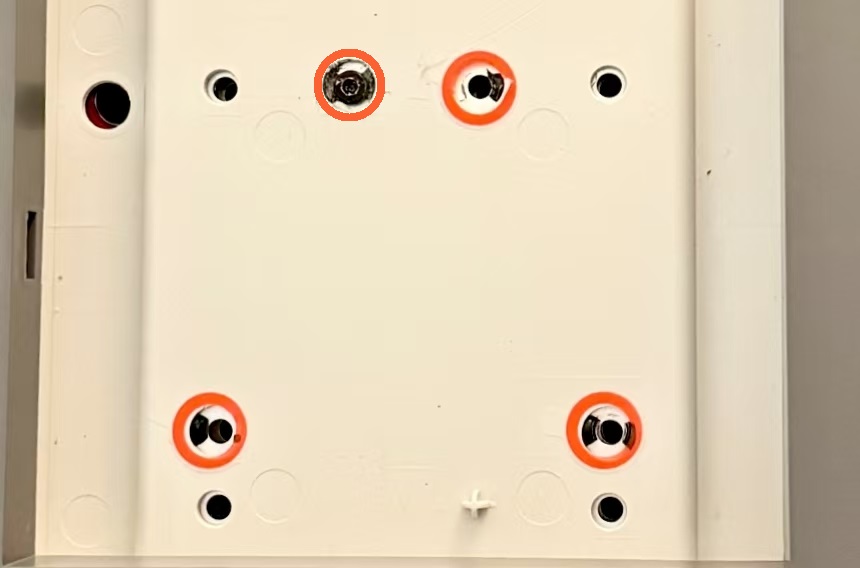
¶ 3.Remove the printer's bottom cover
Remove the 16 screws (BT3-8) at the bottom, and then remove the printer bottom cover one by one.
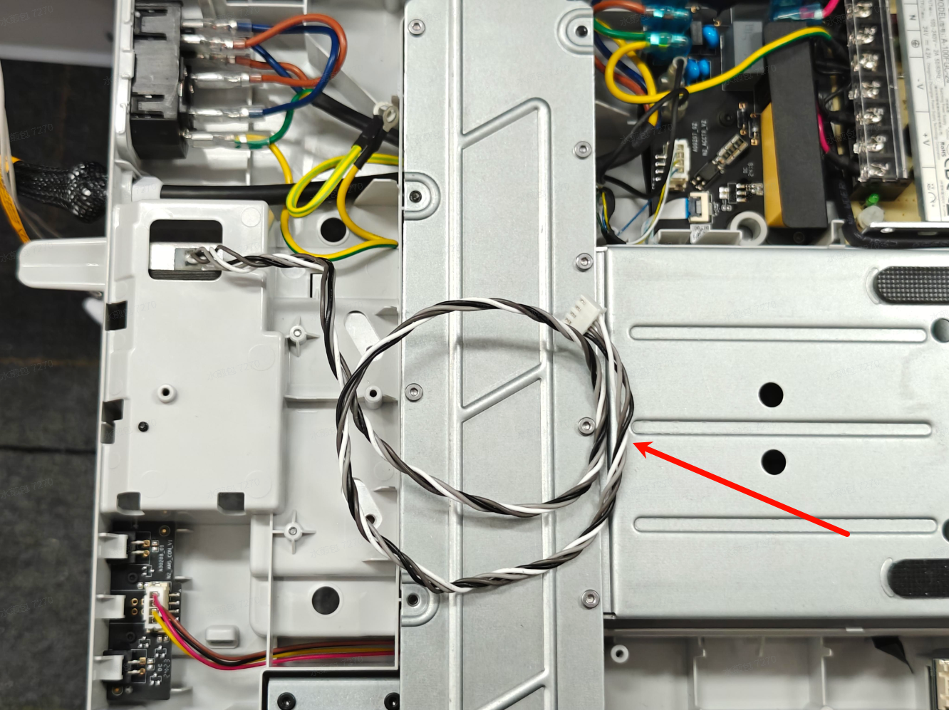
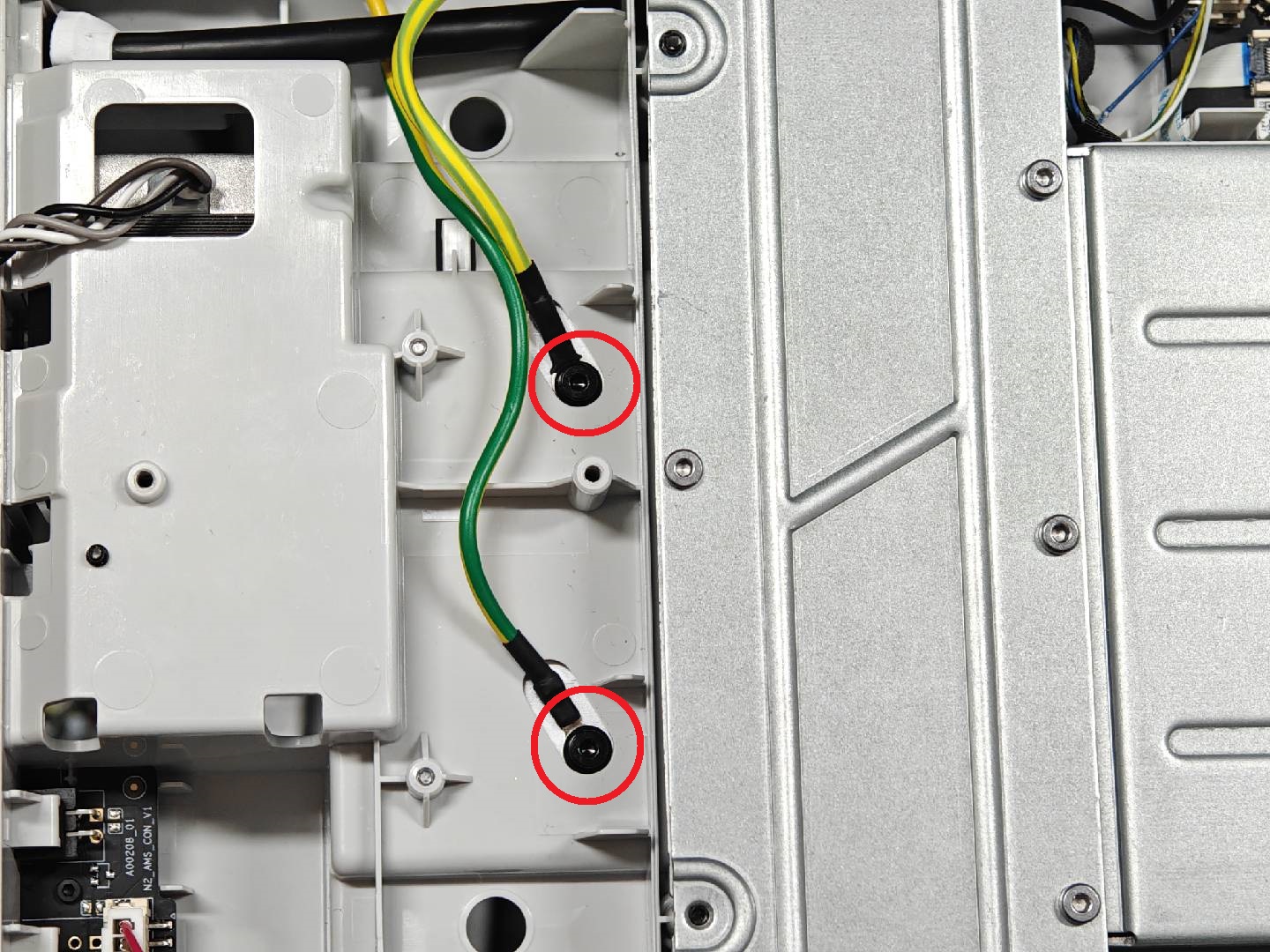
¶ 4.Remove the bottom screws and the Y motor cable
Remove the two fixing screws on the ground cable.This screw is of model M3-6.

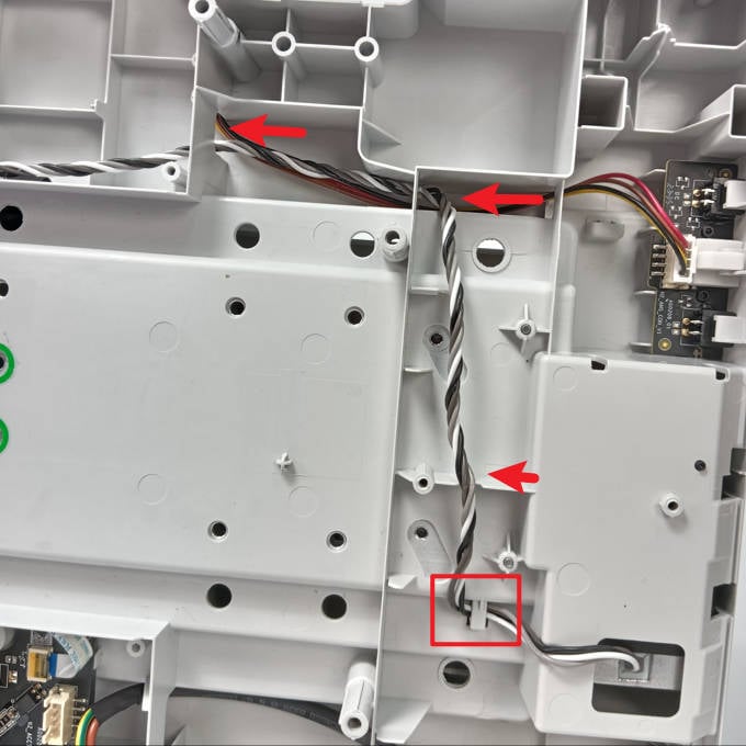
Next, remove the fixing screw for the heat sink and the connector for the Y motor cable.

After removing the Y motor connector, the cables need to be removed from the routing trough to facilitate the removal of the entire Y-axis component in the next step.
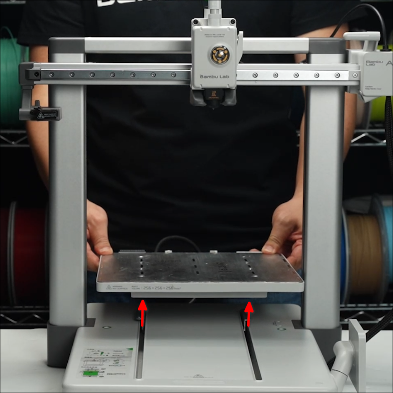
¶ 5.Remove the heatbed and the Y-axis cover plate
Place the A1 printer on a flat surface and slowly raise the X-axis to the top.
Move the heatbed to the bottom and remove the cover on the Y-axis.
 |
 |
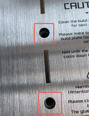
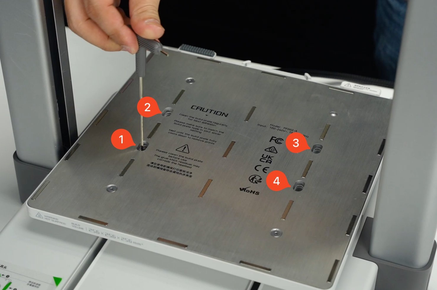
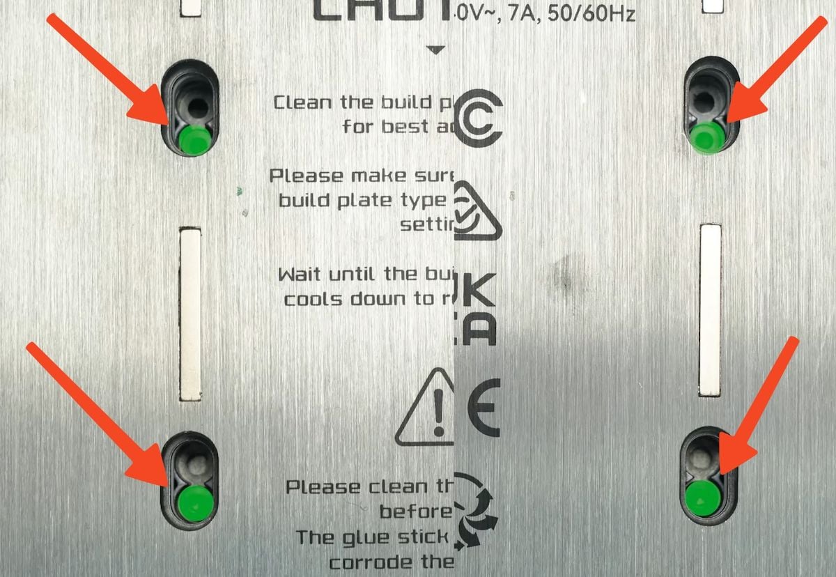
Before removing the heatbed, it is necessary to use the H2.0 hex wrench to remove the 4 soft silicone sleeves;
Then loosen the 4 screws that fix the heatbed, remove the heatbed from the base and place it on the desktop.
This screw is of model M3-6.
 |
 |
Note: The latest version of the heatbed has removed the soft rubber stopper.
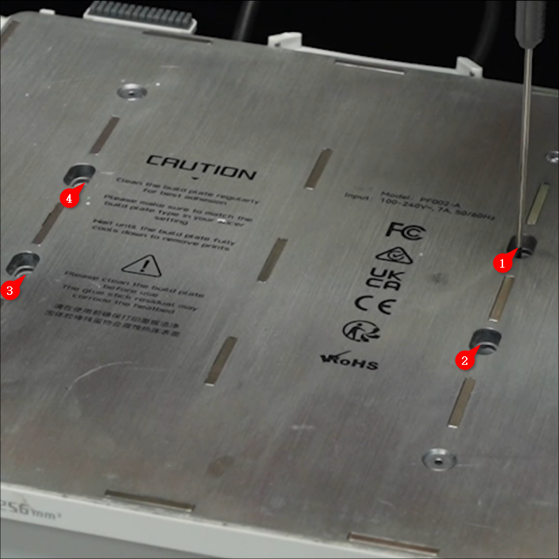
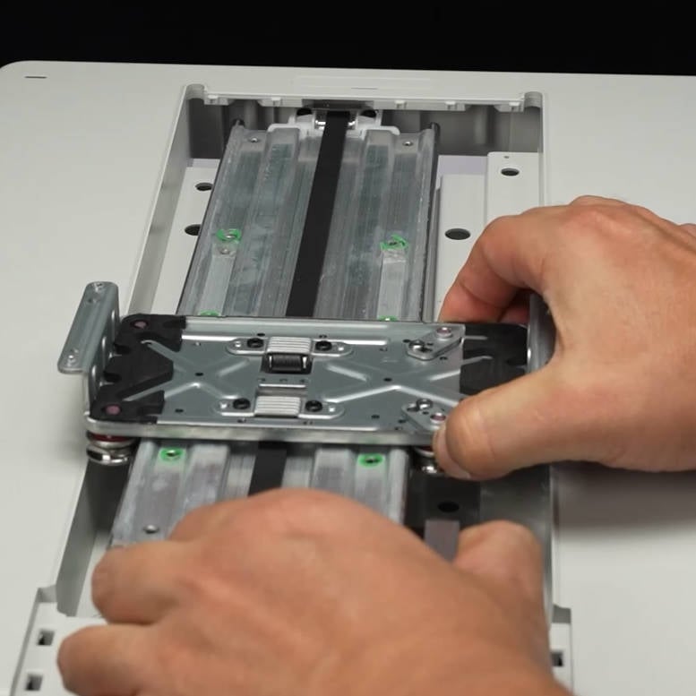
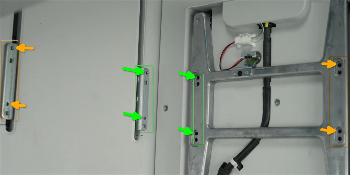
¶ 6.Remove the Y-axis Linear Guide Assembly
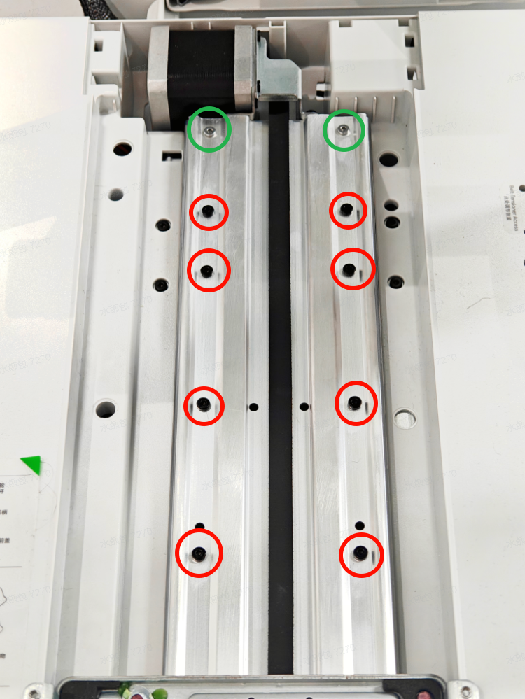
First, the Y-axis slide block needs to be moved to the front end to remove the 8 red-marked screws and 2 green-marked screws shown in Figure 8.
After the screws are removed, move the pulley to the tail end and then remove the 2 green-marked screws at the front end.
The red-marked screws are M3-23 and the green-marked ones are BT3-23.
 |
 |
Then remove the fixing screws of the tail motor.

At this point, the Y-axis linear guide assembly can be completely removed.
Note: In some versions, the Y-axis linear guide assembly and the base may be adhered together with glue. Before removing them, it is necessary to clean off the remaining glue.
¶ Install the new Y-axis Linear Guide Assembly
¶ 1.Install the new Y-axis Linear Guide Assembly
Pass the Y motor cable through from the bottom. First, insert a section of the tensioner into the base, then install the Y motor end;
After the installation is completed, first lock the black screw at the Y motor position. This screw can be used to confirm whether the installation is in place.
 |
|
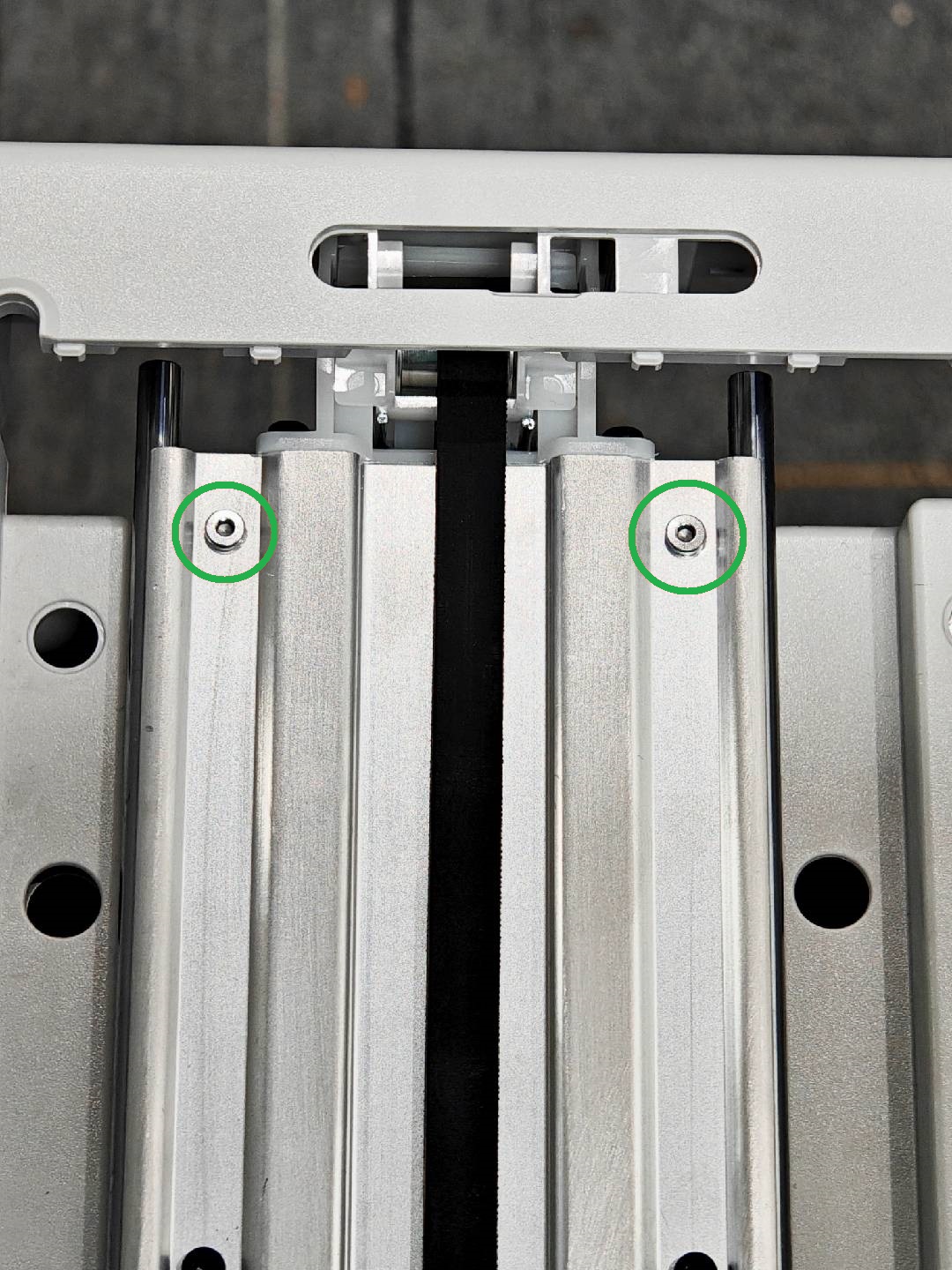
First, install four green-marked screws at both ends, and then install eight red-marked screws at the middle position.
The red-marked screws are M3-23 and the green-marked ones are BT3-23.
|
|
¶ 2.Connect the Y motor cable and the bottom screws
Pass the Y motor cable through the bottom wiring trough.
 |
 |
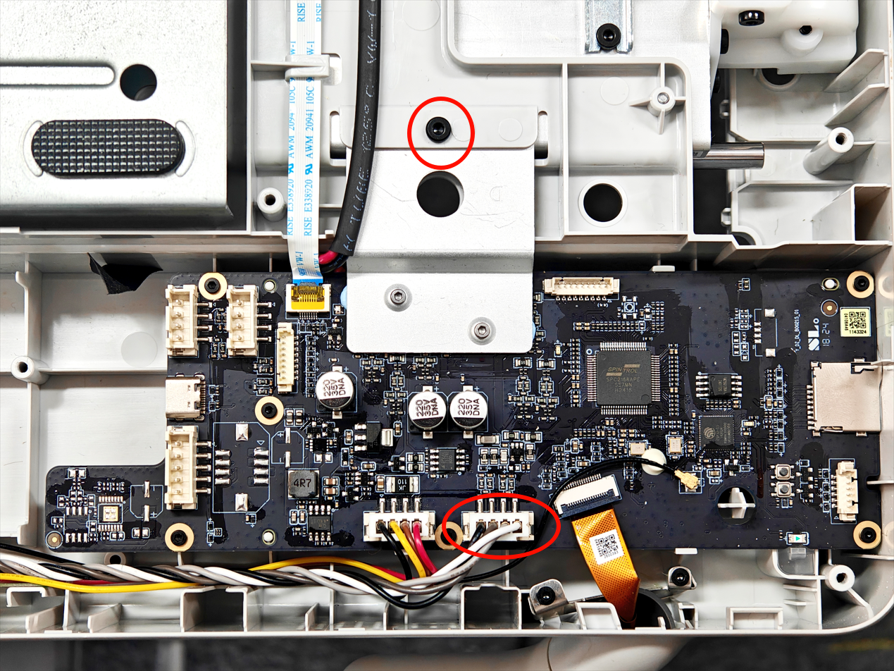
Install two ground cable fixing screws(M3-6);
Connect the Y motor connector and tighten the fixing screws of the heat sink.
 |
 |
¶ 3.Install the printer bottom cover
Now the printer bottom cover can be installed; it should be noted that the position of the cable bracket for the motor cable. Before inserting the cable connector, avoid the bottom cover pressing on the motor cable;
After the bottom cover is installed, lock in the corresponding 16 screws (BT3-8) . Here, the screws are self-tapping screws. Avoid over-tightening.
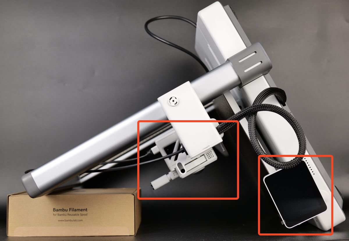
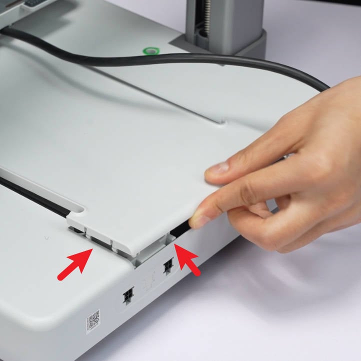
¶ 4.Install the wire bracket and connect the wires
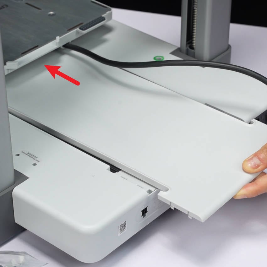
In the final step, carefully align the wire bracket then push it downwards while making sure the USB cable is fully pushed against the printer frame.
Then, tighten the screw shown in the image to lock it in place. Avoid overtightening the screw as this is screwed into the plastic frame. This screw is of model BT3-27.
Next, re-connect the Camera, Motor X and Motor Z cables to finish the installation.
This completes the installation process
¶ 5.Install the heatbed component and the Y-axis cover plate
Carefully align the heatbed metallic frame to the two metallic stands on the Y-axis, while ensuring the screw holes of the bed are aligned.
Proceed with installing the four screws(M3-6) on the heatbed as shown in the image below. When done, you can also install the four silicone covers removed before.
 |
 |
Note: The latest version of the heatbed has removed the soft rubber stopper and modified it to have only one screw hole.
The only differences between the old and new versions of the hot bed are the soft rubber stopper and the screw hole; the update of the heatbed is aimed at preventing incorrect installation during replacement.
Move the hot bed forward to the end, pass the Y-axis cover from beneath the hot bed through, and push it forward to the end. Align the snap fasteners and install the Y-axis cover in place.
 |
 |
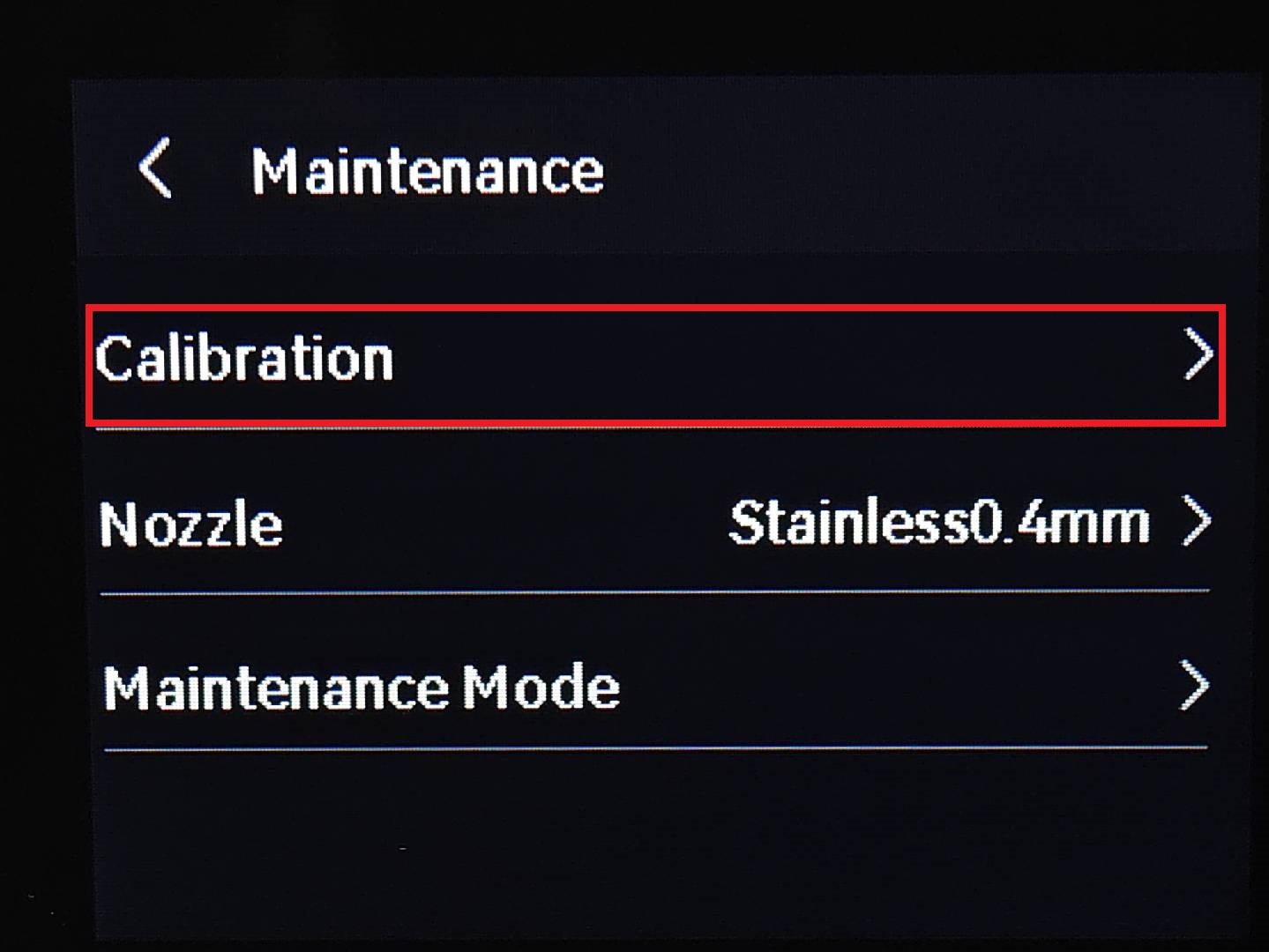
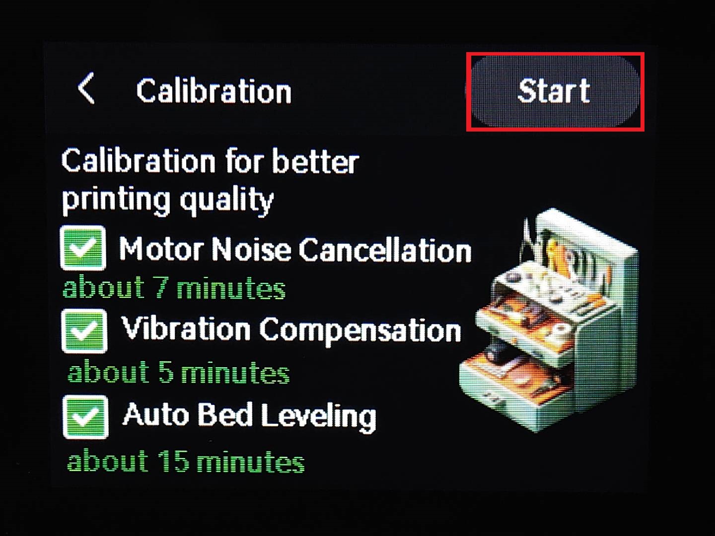
¶ Printer calibration
To ensure that the Y-axis component replacement does not affect the normal operation of the printer, you need to recalibrate the device before the actual printing.
 |
 |
¶ End Notes
We hope the detailed guide provided has been helpful and informative.
If this guide does not solve your problem, please submit a technical ticket, we will answer your questions and provide assistance.
If you have any suggestions or feedback on this Wiki, please leave a message in the comment area. Thank you for your support and attention!