¶ Power switch
Hereinafter, we will present the detailed steps for replacing the A1 power switch.
.jpg)
¶ Applicable models of printers
Bambu Lab A1
¶ When to use?
- The printer won't turn on.
- Poor contact of power cable.
- Recommended by Bambu Lab customer support
¶ Tools and materials needed
- New power switch
- H2.0 hex wrench
- PH2 Philips screwdriver
- 20 minutes
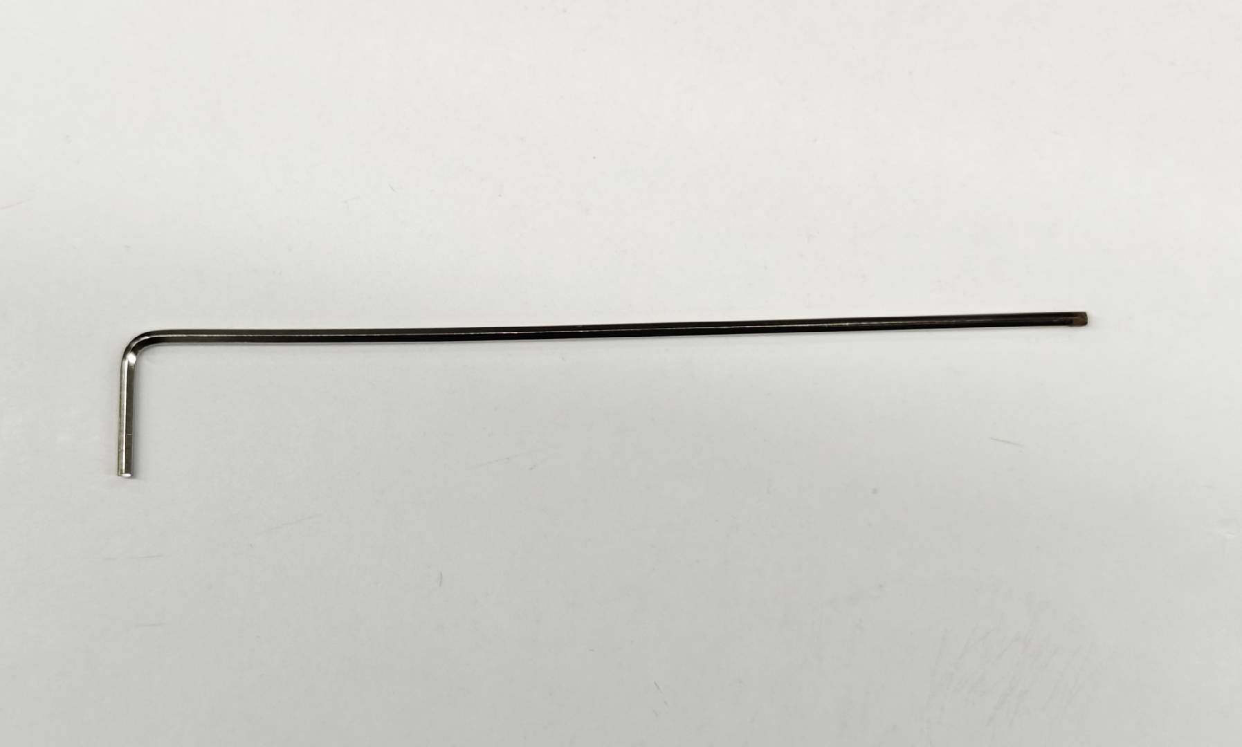
Note: Before proceeding, you need to find a 90-degree bent H2.0 hex wrench or a similar tool for removing the power switch.
¶ Safety Warning
It's crucial to power off the printer before conducting any maintenance work, including work on the printer's electronics and tool head wires. Performing tasks with the printer on can result in a short circuit, leading to electronic damage and safety hazards.
During maintenance or troubleshooting, you may need to disassemble parts, including the hotend. This exposes wires and electrical components that could short circuit if they contact each other, other metal, or electronic components while the printer is still on. This can result in damage to the printer's electronics and additional issues.
Therefore, it's crucial to turn off the printer and disconnect it from the power source before conducting any maintenance. This prevents short circuits or damage to the printer's electronics, ensuring safe and effective maintenance. For any concerns or questions about following this guide, open a new ticket in our Support Page and we will do our best to respond promptly and provide the assistance you need.
¶ Remove the old power switch
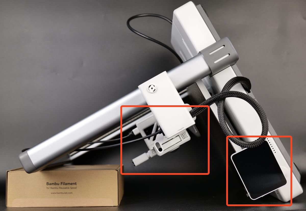
¶ 1.Place the printer on its front
For easy access to the bottom section of the A1, you need to place the printer on the front.
Start by flipping the screen on its side, then gently place the printer on its front, as shown in the image below.
Use a box of filament to keep the top side raised to avoid putting pressure on the extruder and the screen.
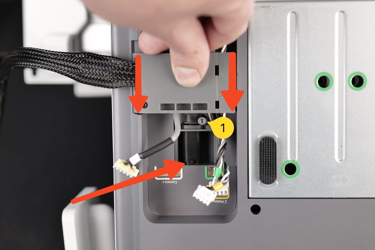
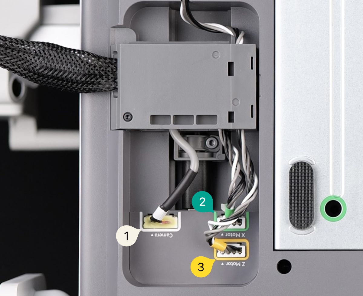
¶ 2.Disconnect the cable and remove the cable bracket
Loosen the yellow-marked screws without completely removing them. After removing the 1st, 2nd and 3rd cables, which are the camera, Z-axis motor and X-axis motor respectively, push up the cable bracket to disconnect the USB-C cable.
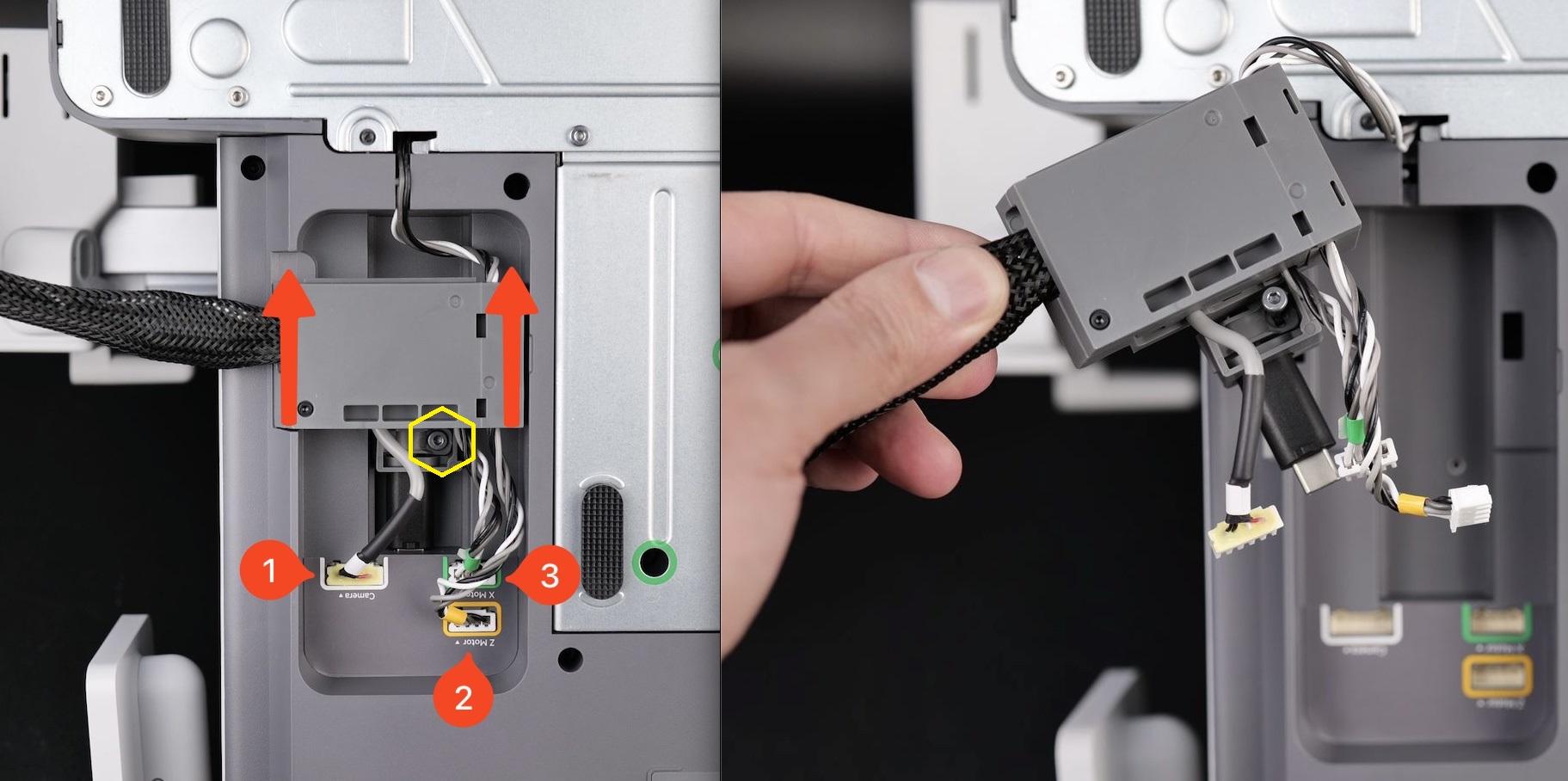
Note: If it is not easy to remove the cable bracket, you can completely remove the yellow-marked screws and try again.
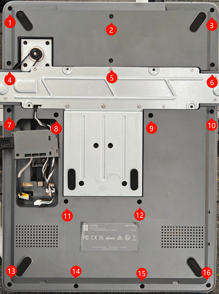
¶ 3.Remove the printer's bottom cover
Remove the 16 screws at the bottom, and then remove the printer bottom cover one by one.
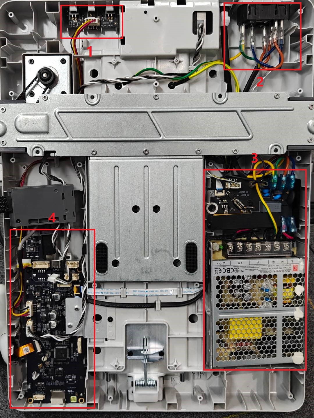
After removing the bottom cover, the following four areas can be seen. The replacement steps for this time are in Area 2 and Area 3.
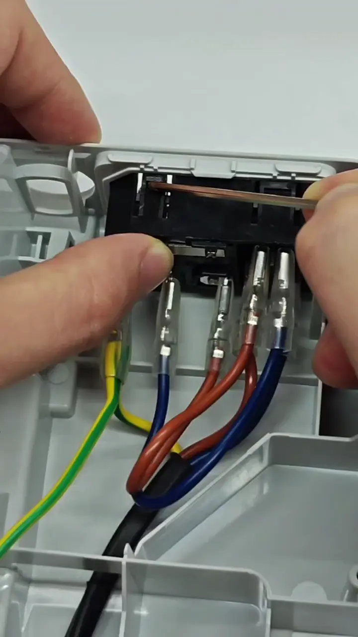
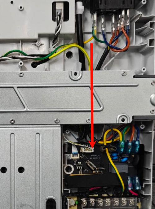
¶ 4.Remove the power switch cable
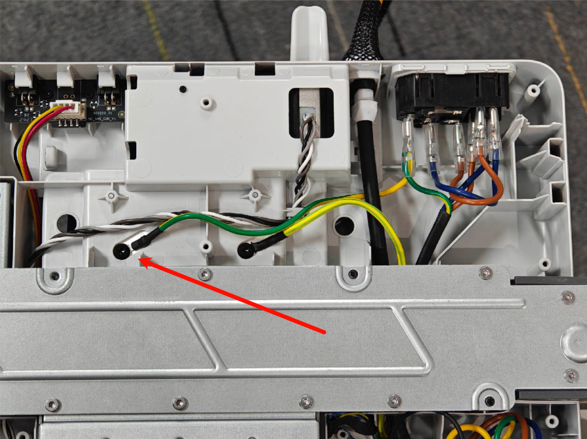
First, the ground cable of the power switch needs to be disconnected.
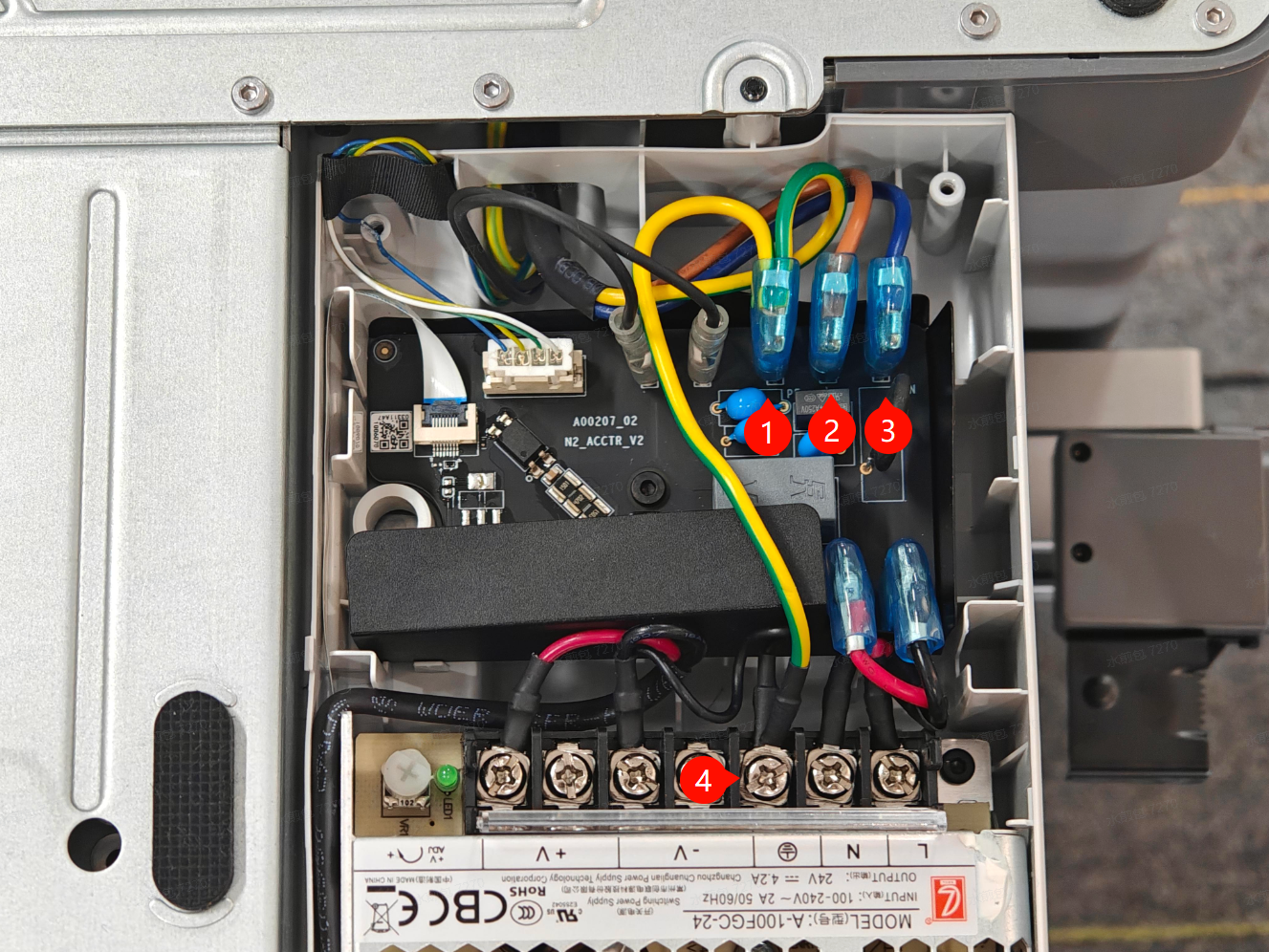
Remove the four cable connectors as shown in the following figure one by one.
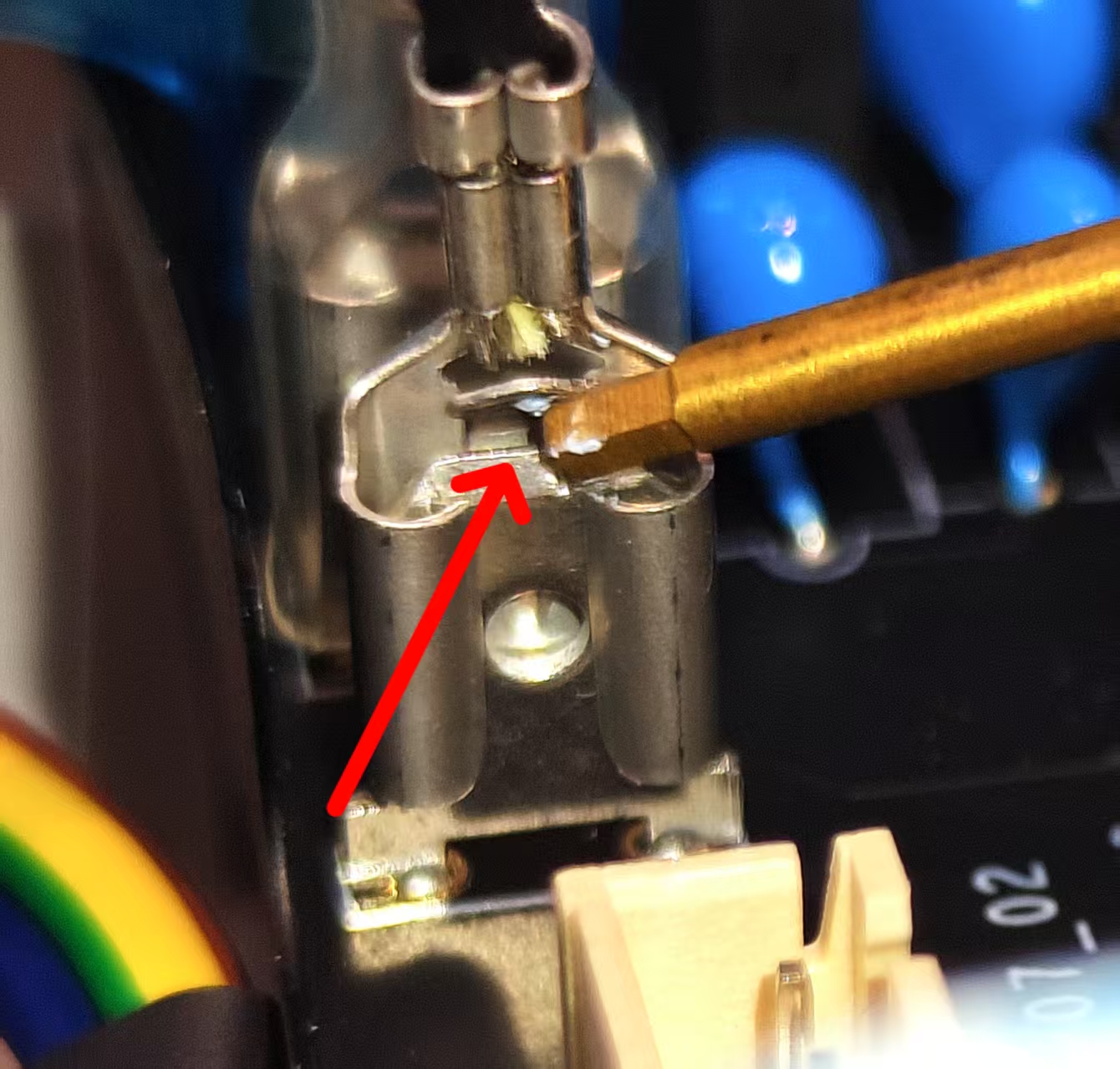
Note: If the 1st, 2nd and 3rd connectors are removed, it will be rather difficult. In such cases, you can use an internal hex wrench to press against the unlock latch before removing the cable connector.
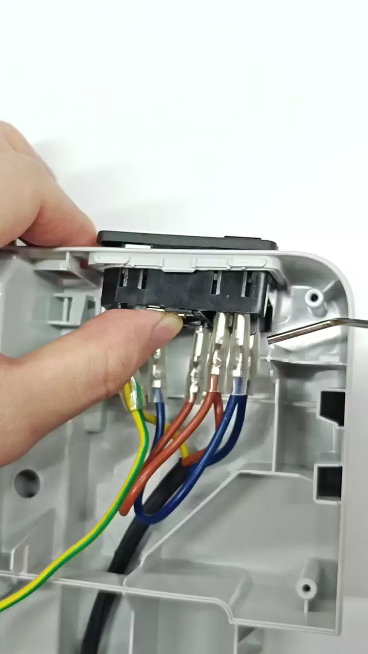
¶ 5.Remove the power switch
The removal of the power switch can be carried out in the following three steps:
1. Release the two top retaining clips.
After releasing the snap fastener, you need to keep pressing it with your fingers to prevent it from slipping off again.
2. While pushing forward from the rear side of the switch, release the snap fastener at the bottom right corner. At this point, three snap fasteners have been released.
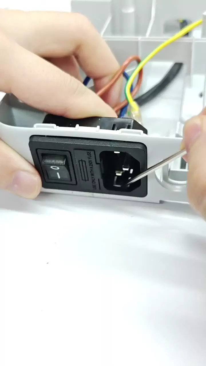
3. While pushing forward from the rear side after turning the switch, release the snap fastener at the bottom right corner and remove the power switch.
Use the shorter end of the hex wrench and press it upwards against the lower latch to release it.
At this point, the old power switch has been completely removed. Next, the new power switch can be installed.
¶ Install a new power switch
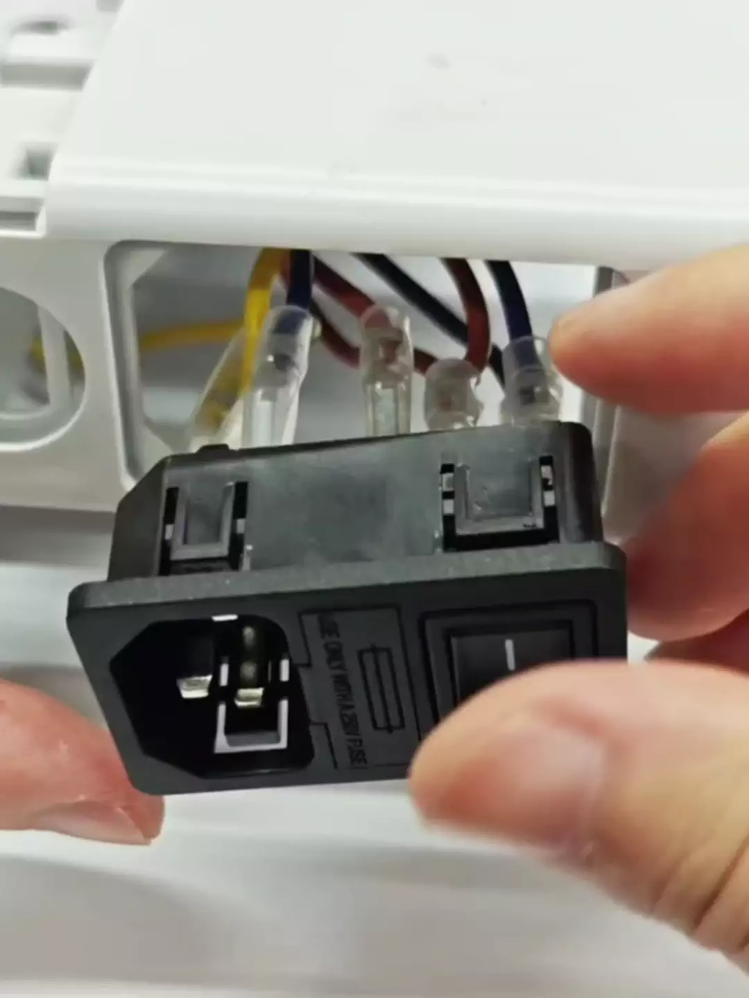
¶ 1.Install the power switch
Align the power switch with the slot and push it in. The snap lock will automatically engage.
Note: The switch button is located close to the outer side of the printer.
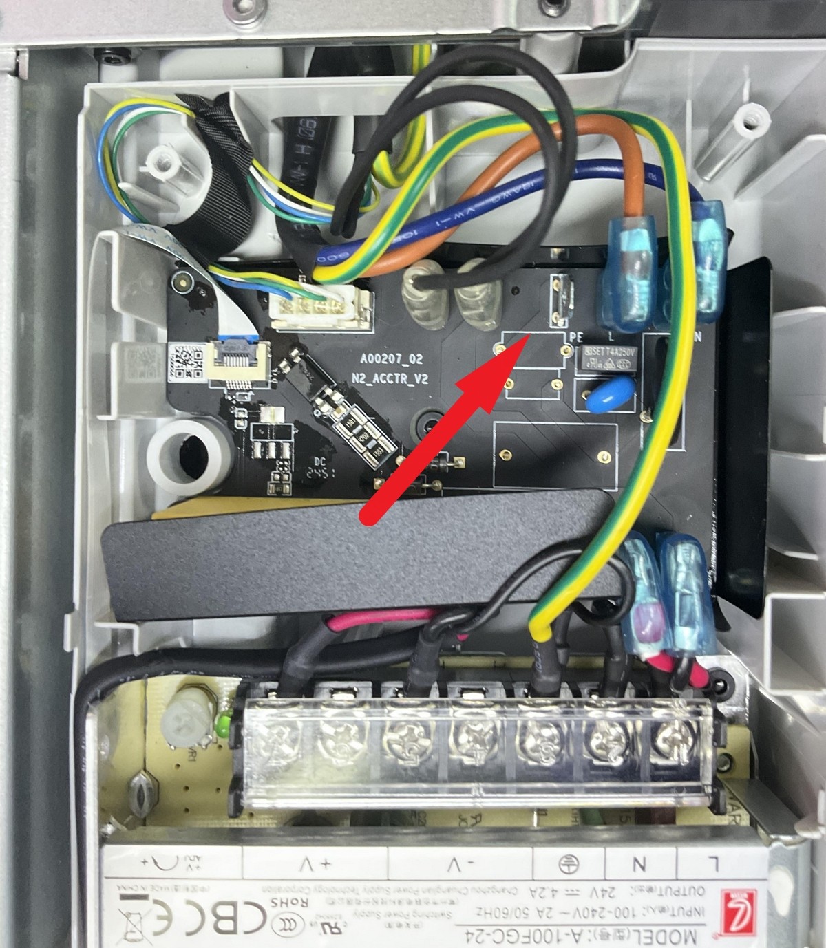
¶ 2.Power supply connection cable
- Connect the ground cable
Note: In the new version of the A1 power switch, we have optimized the cable layout by removing the intermediate ground wire connector to the AC board. Functional and safety tests have verified that this change does not affect the normal operation of the power switch or the overall system, while also reducing the number of connection points and improving the reliability and simplicity of the cable layout.
- The power switch cable needs to pass through the bottom trough.
- Connect the cable to the AC board and the power module.
#1 Ground cable of AC board(yellow)
#2 Live(brown)
#3 Neutral(blue)
#4 Ground cable of power supply(yellow)
After the cable installation is completed, please pay attention to installing the rubber sleeves to avoid short circuits.
Note: The new version of the AC board has removed the ground wire design and optimized the power switch and current-carrying capacity. This change does not affect the core functions and performance of the AC board.
¶ 3.Install the printer's bottom cover
Now the printer bottom cover can be installed; it should be noted that the position of the cable bracket for the motor cable. Before inserting the cable connector, avoid the bottom cover pressing on the motor cable;
After the bottom cover is installed, lock in the corresponding 16 screws. Here, the screws are self-tapping screws. Avoid over-tightening.
¶ 5.Install the cable bracket and connect the cables
In the final step, carefully align the cable bracket then push it downwards while making sure the USB cable is fully pushed against the printer frame.
Then, tighten the screw shown in the image to lock it in place. Avoid overtightening the screw as this is screwed into the plastic frame.
Next, re-connect the Camera, Motor X and Motor Z cables to finish the installation.
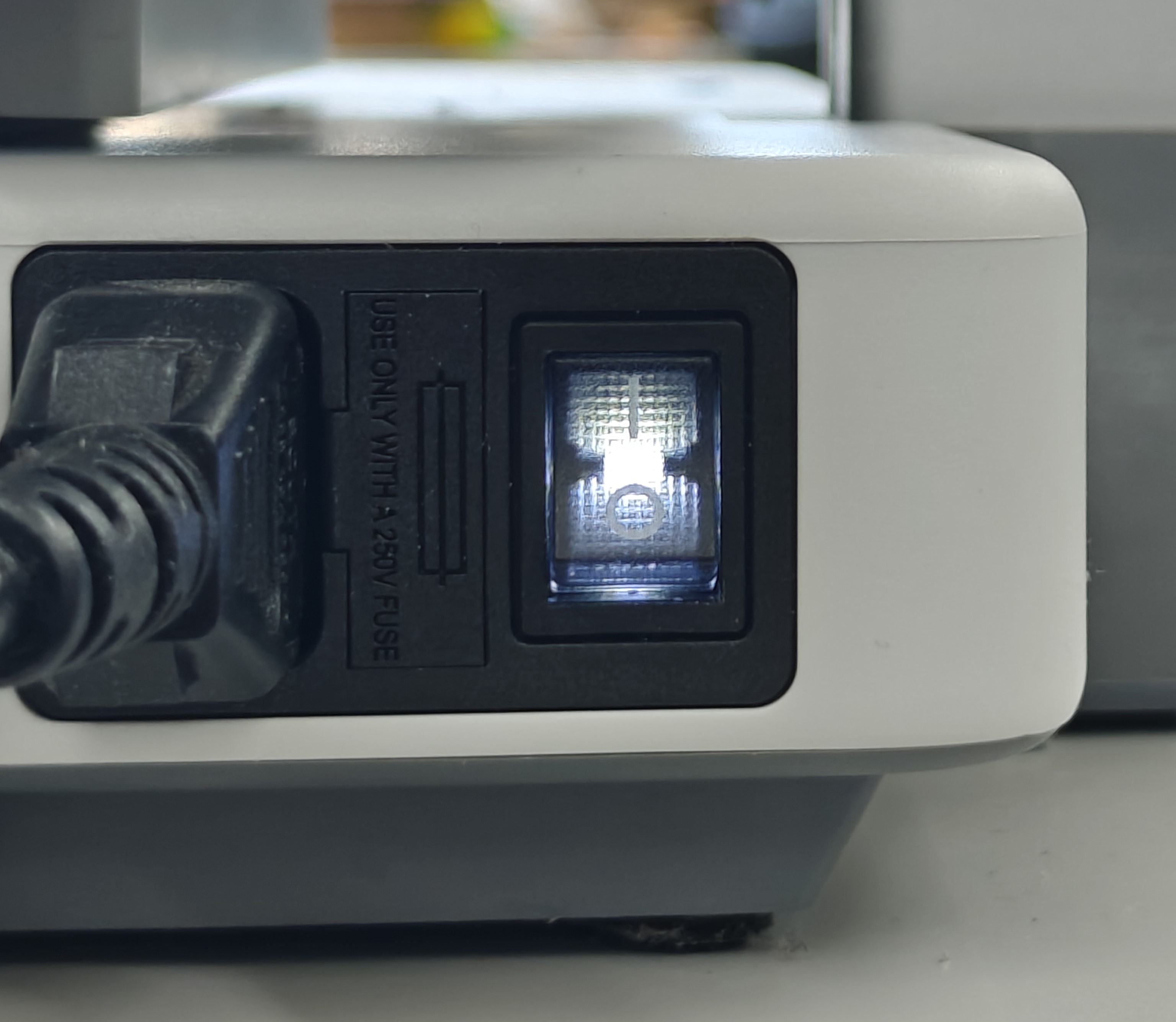
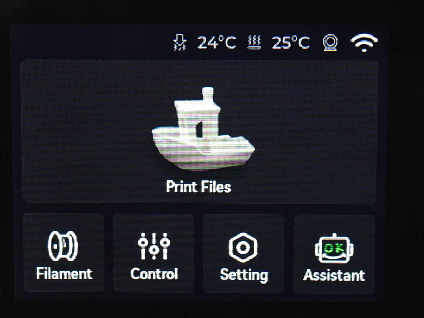
¶ Verify the functionality
After the installation is completed, connect the printer to the power supply, turn on the power switch, and if the indicator lights and the screen light up normally, the installation is successful and the printing test can be carried out.
 |
 |
¶ End Notes
We hope that the detailed guide we shared with you was helpful and informative.
We want to ensure that you can perform it safely and effectively. If you have any concerns or questions regarding the process described in this article, we encourage you to reach out to our friendly customer service team before starting the operation. Our team is always ready to help you and answer any questions you may have.
Click here to open a new ticket in our Support Page.
We will do our best to respond promptly and provide you with the assistance you need.