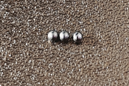
¶ Accidental Fall of Steel Bearing Balls on the X-axis Linear Guideway
The X-axis linear guideway steel bearing balls may usually come out in the following scenarios:
-
When maintaining and lubricating the X-axis idler pulley;
-
When replacing the X belt, X-axi smotor, or X-axis cover.
If the steel bearing balls are not restored, problems such as reduced X-axis accuracy and abnormal sliding noise may occur.
Note: The X-axis linear guideway should not be open, and the toolhead should not be removed if there is no issue or not requested by customer support, to avoid loosing the bearings.
¶ Tools Required
- Steel bearing balls
- H1.5/H2.0 Allen key
- Tweezers
- 15 minutes
¶ Safety warning
Important!
It's crucial to power off the printer before conducting any maintenance work, including work on the printer's electronics and tool head wires. Performing tasks with the printer on can result in a short circuit, leading to electronic damage and safety hazards.
During maintenance or troubleshooting, you may need to disassemble parts, including the hotend. This exposes wires and electrical components that could short circuit if they contact each other, other metal, or electronic components while the printer is still on. This can result in damage to the printer's electronics and additional issues.
Therefore, it's crucial to turn off the printer and disconnect it from the power source before conducting any maintenance. This prevents short circuits or damage to the printer's electronics, ensuring safe and effective maintenance.
For any concerns or questions about following this guide, please open a new ticket in our Support Page and we will do our best to respond promptly and provide the assistance you need.
¶ Video Guide
https://public-cdn.bblmw.com/wiki/A1/troubleshooting/a1-x-axis-en.mp4
¶ Remove the Toolhead
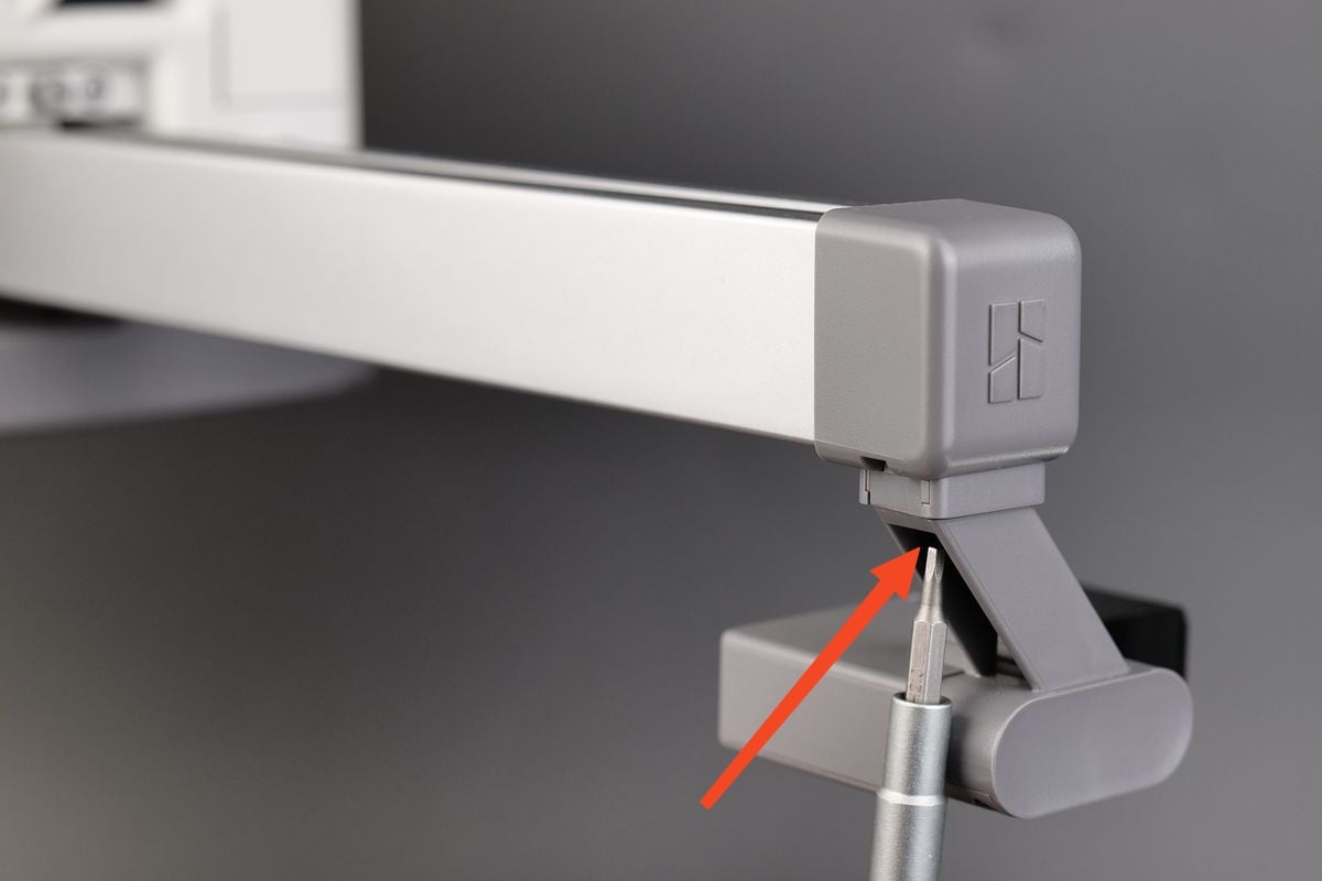
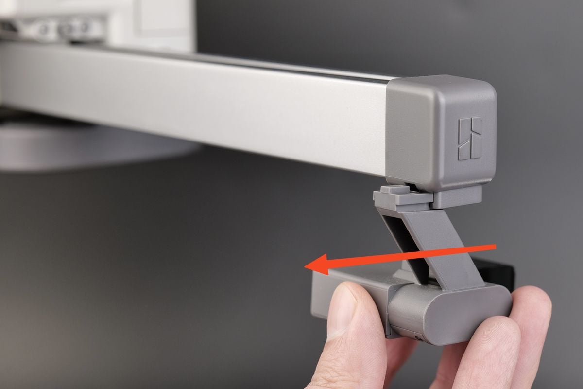
¶ Step 1: Remove the AMS lite Filament Hub
Use a key to slightly pry up the AMS lite filament hub and remove it.
Note: The base of the filament sensor is coated with damping grease.
 |
 |
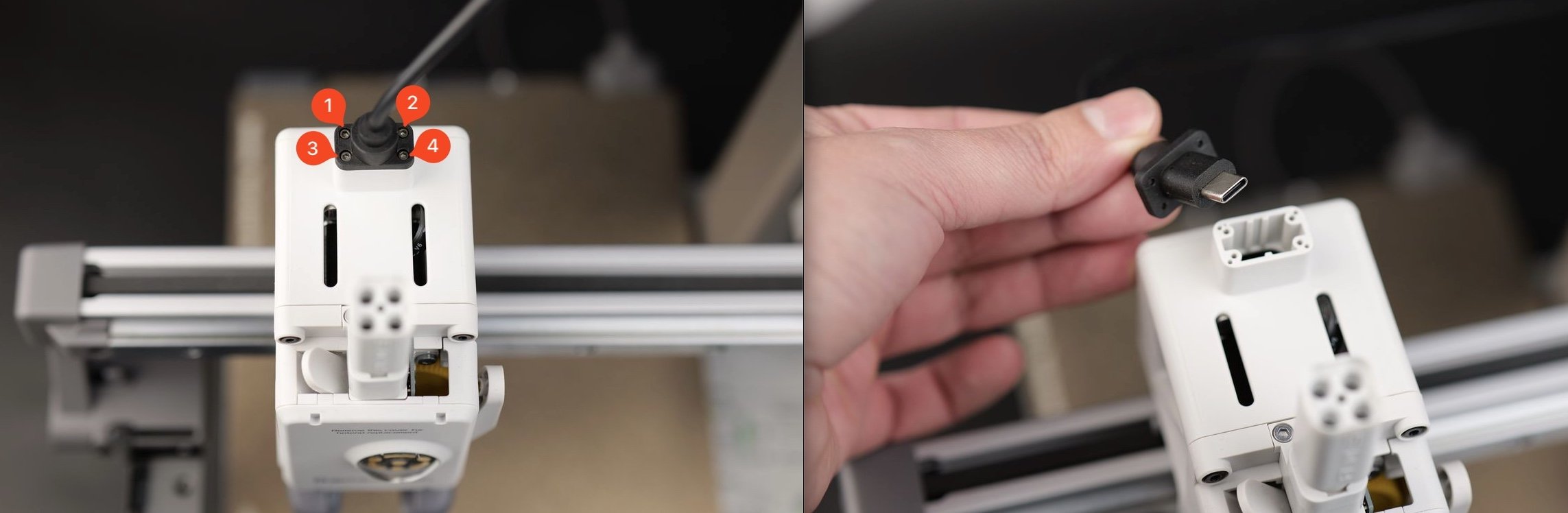
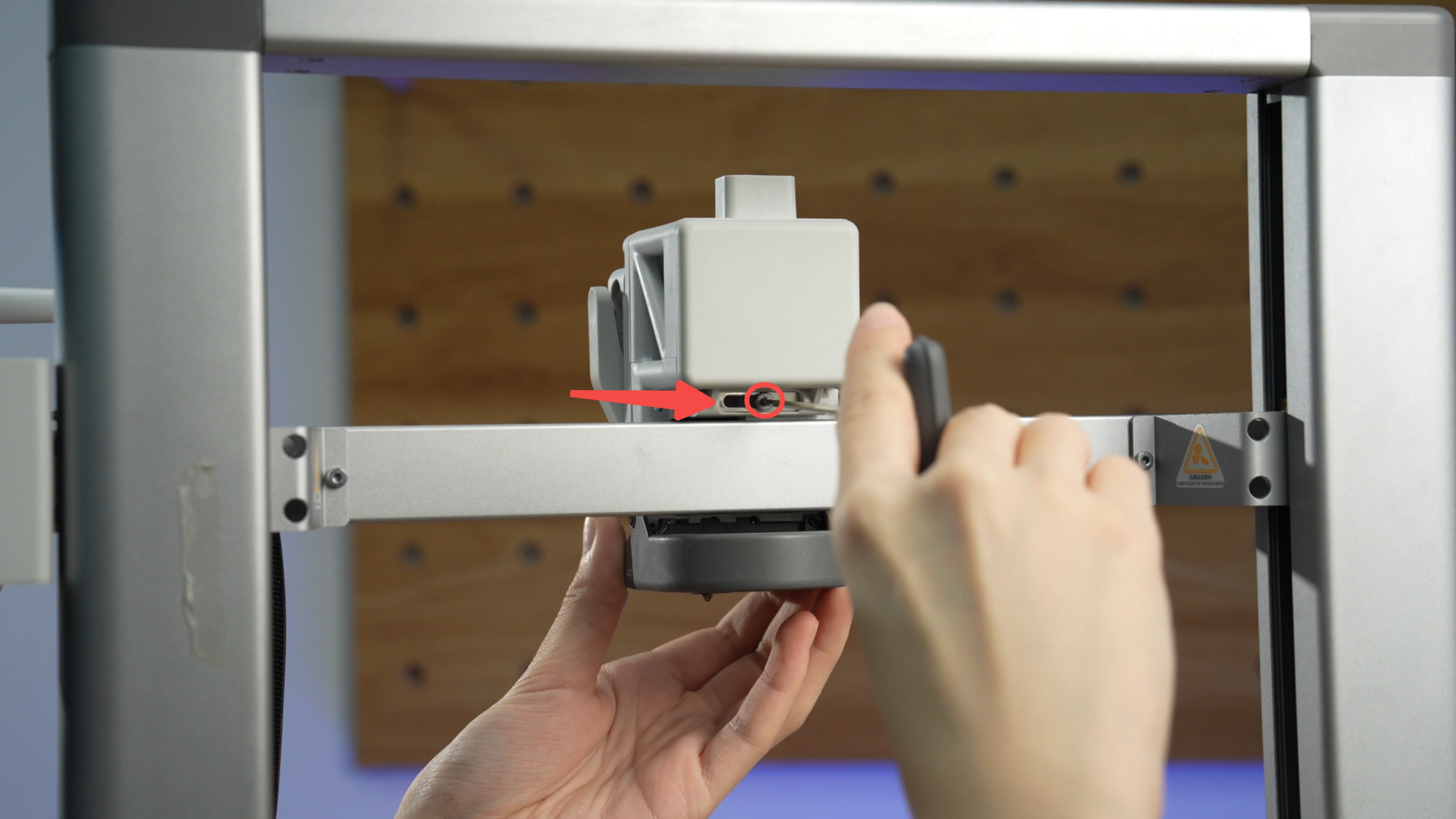
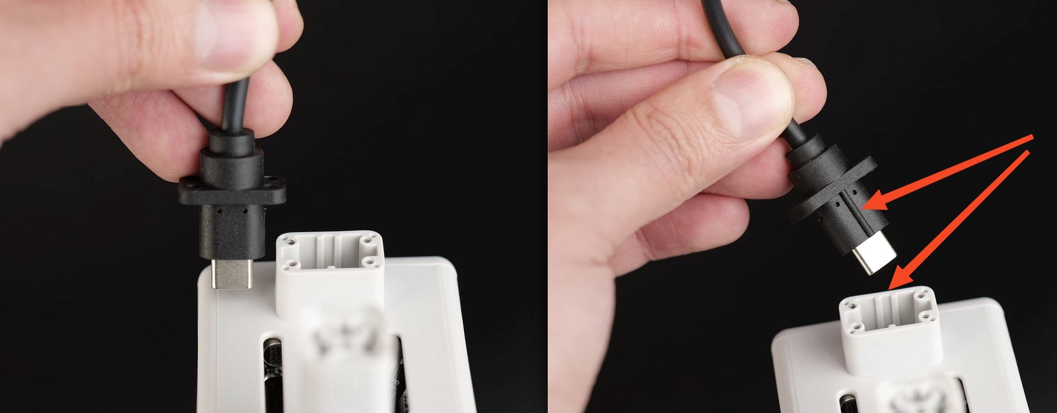
¶ Step 2: Disconnect the USB-C cable
Use an H1.5 Allen key to remove the 4 screws and disconnect the USB-C cable from the toolhead.
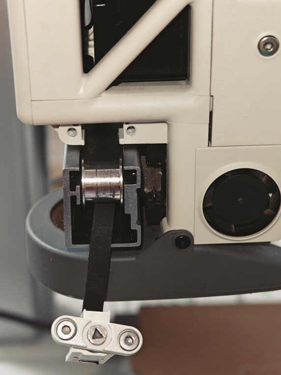
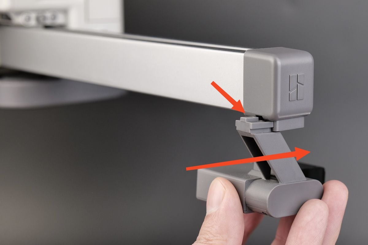
¶ Step 3: Remove the purge wiper
Loosen the screws under the purge wiper, and then slide the purge wiper out of the bracket according to the direction shown in the picture.
 |
 |
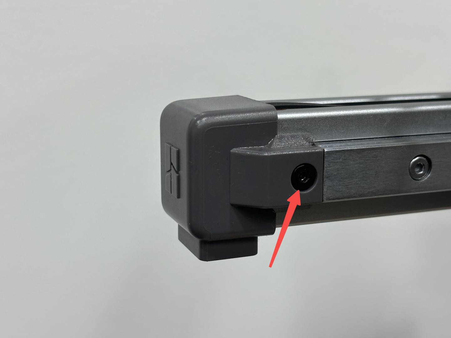
¶ Step 4: Remove the X-axis cover
Use H2.0 Allen key to remove a screw, and remove the X-axis cover.
Note: The cover screw is shorter than the purge wiper screw. Please distinguish the two screws to avoid errors during subsequent installation.
 |
 |
|---|
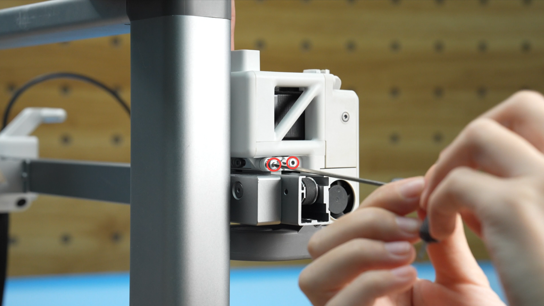
¶ Step 5: Remove the screws on the back and left side of the toolhead
Remove the 1 screw behind the toolhead and the 2 screws on the left side, and remove the left block.
Note: There is a slight interference between the upper part of the left block and the toolhead front cover. When pulling it out, you need to press the block downwards to prevent the upper part of the block from getting stuck.
 |
 |
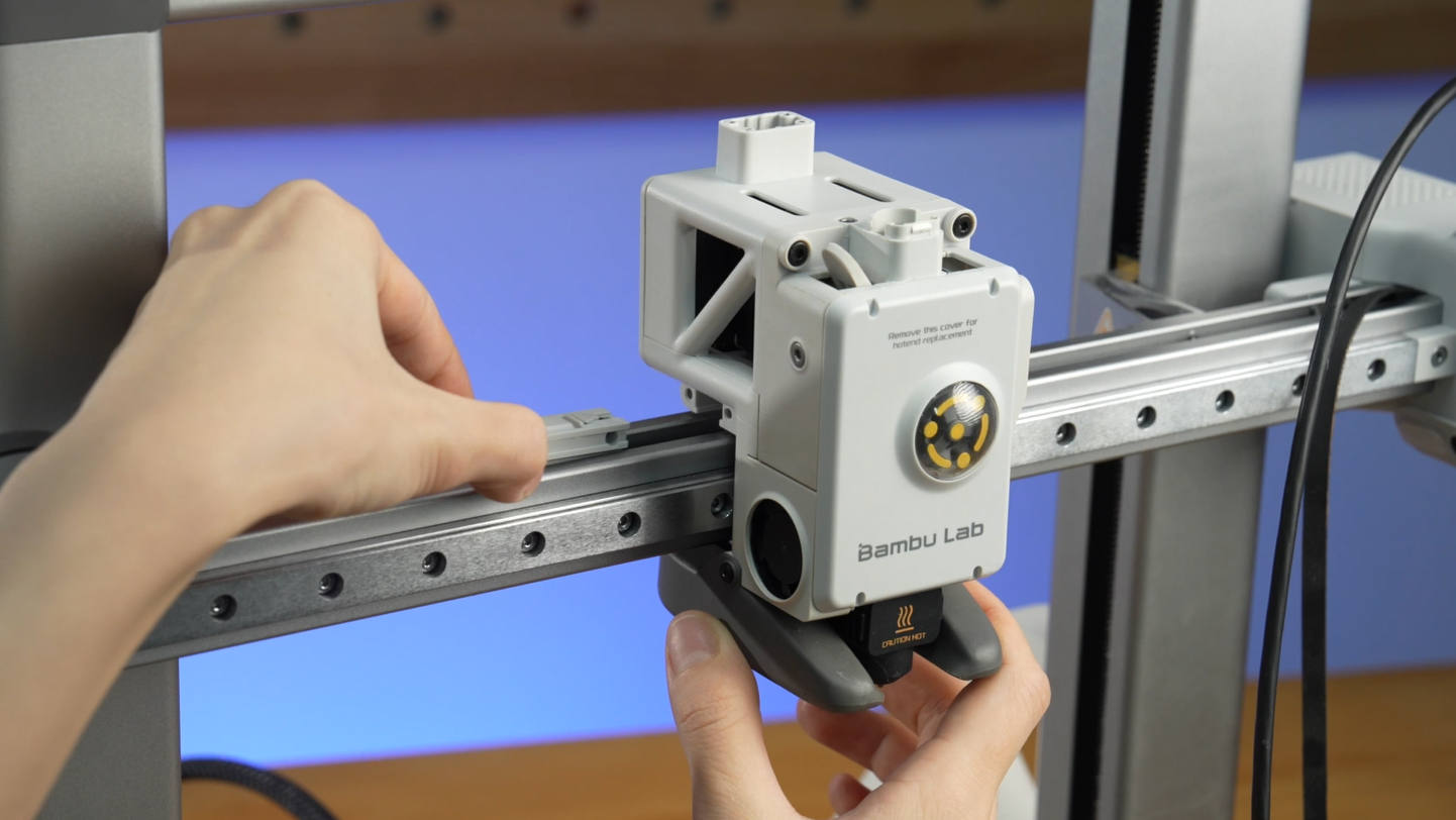 |
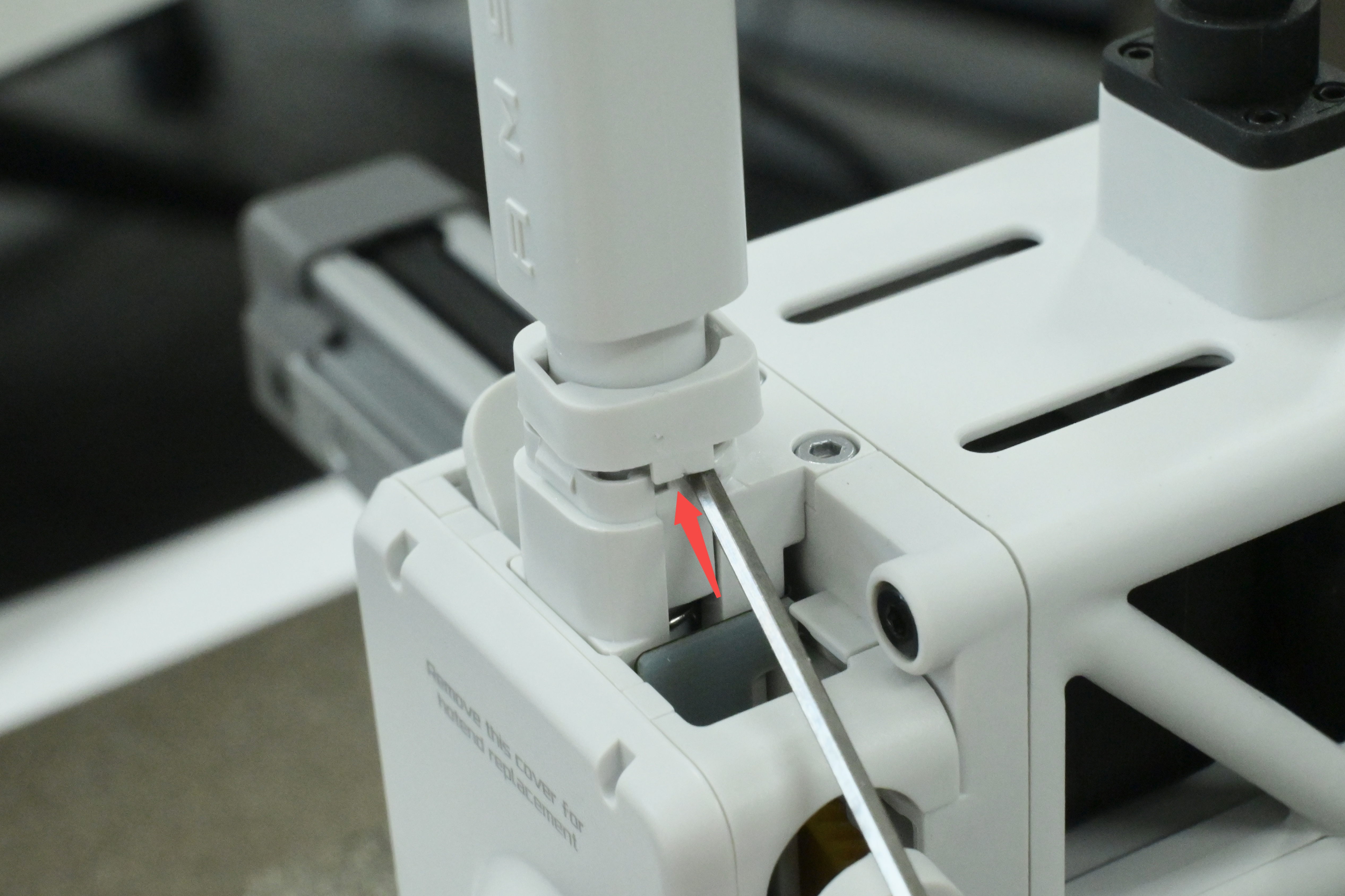
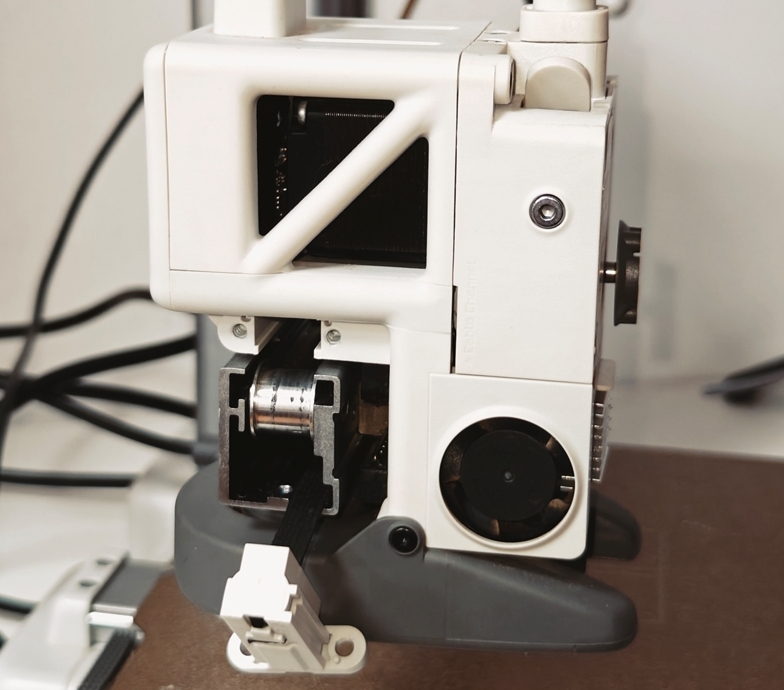
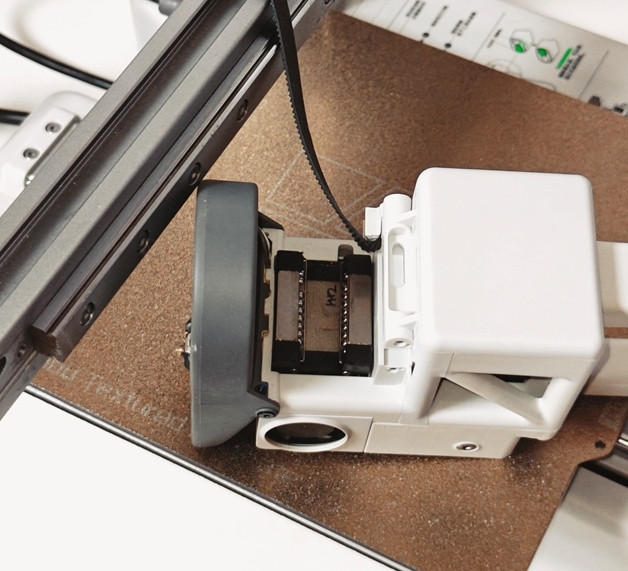
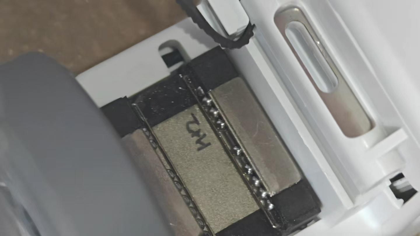
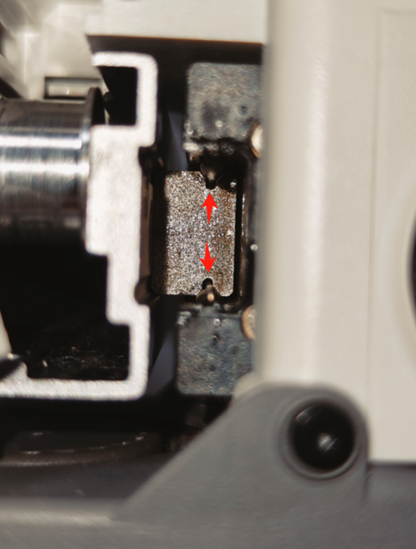
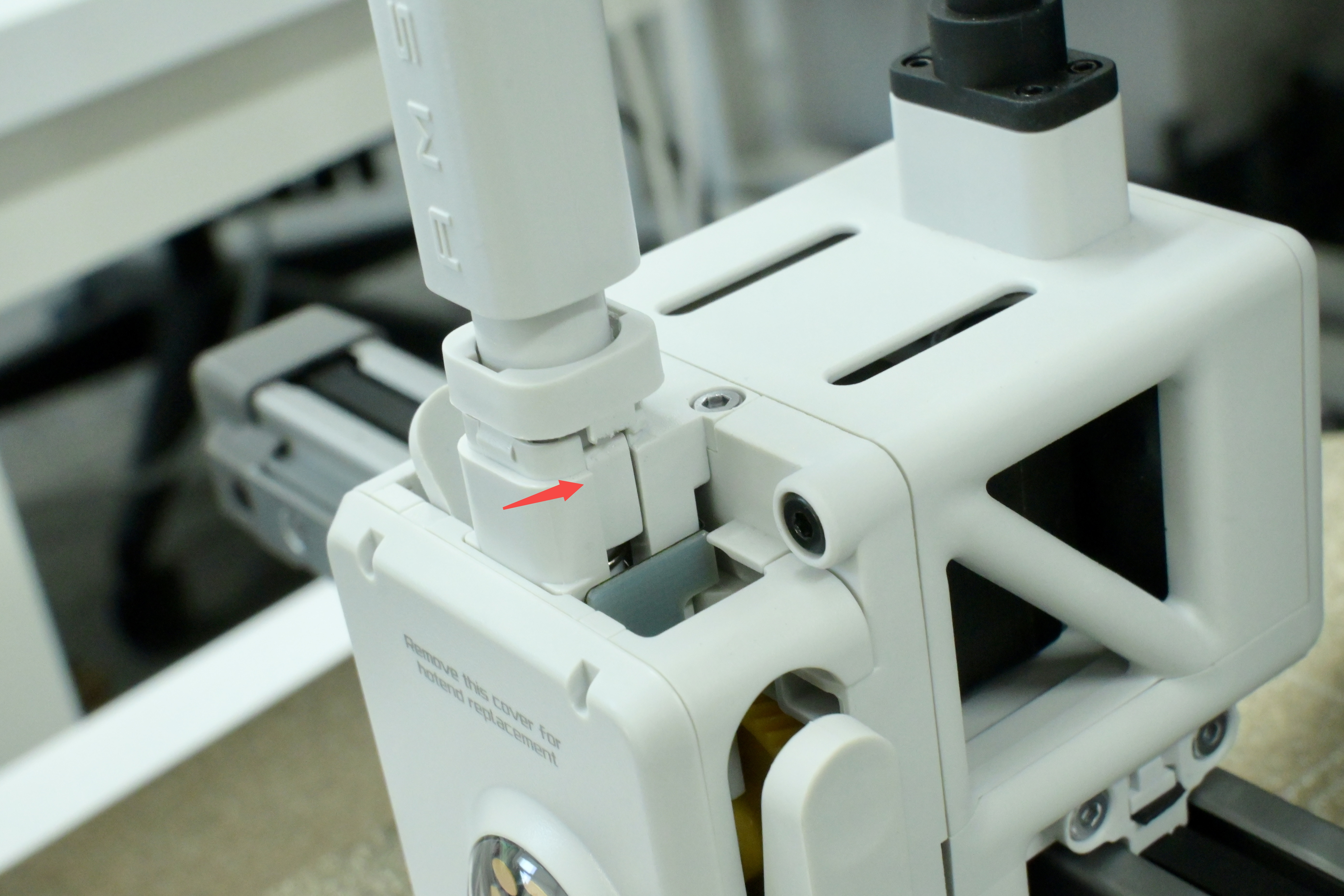
¶ Step 6: Remove the toolhead
Slowly remove the toolhead from the guide rail and place it with the steel bearing balls facing up.
Note: Perform this step slowly to prevent further fall of steel bearing balls.
 |
 |
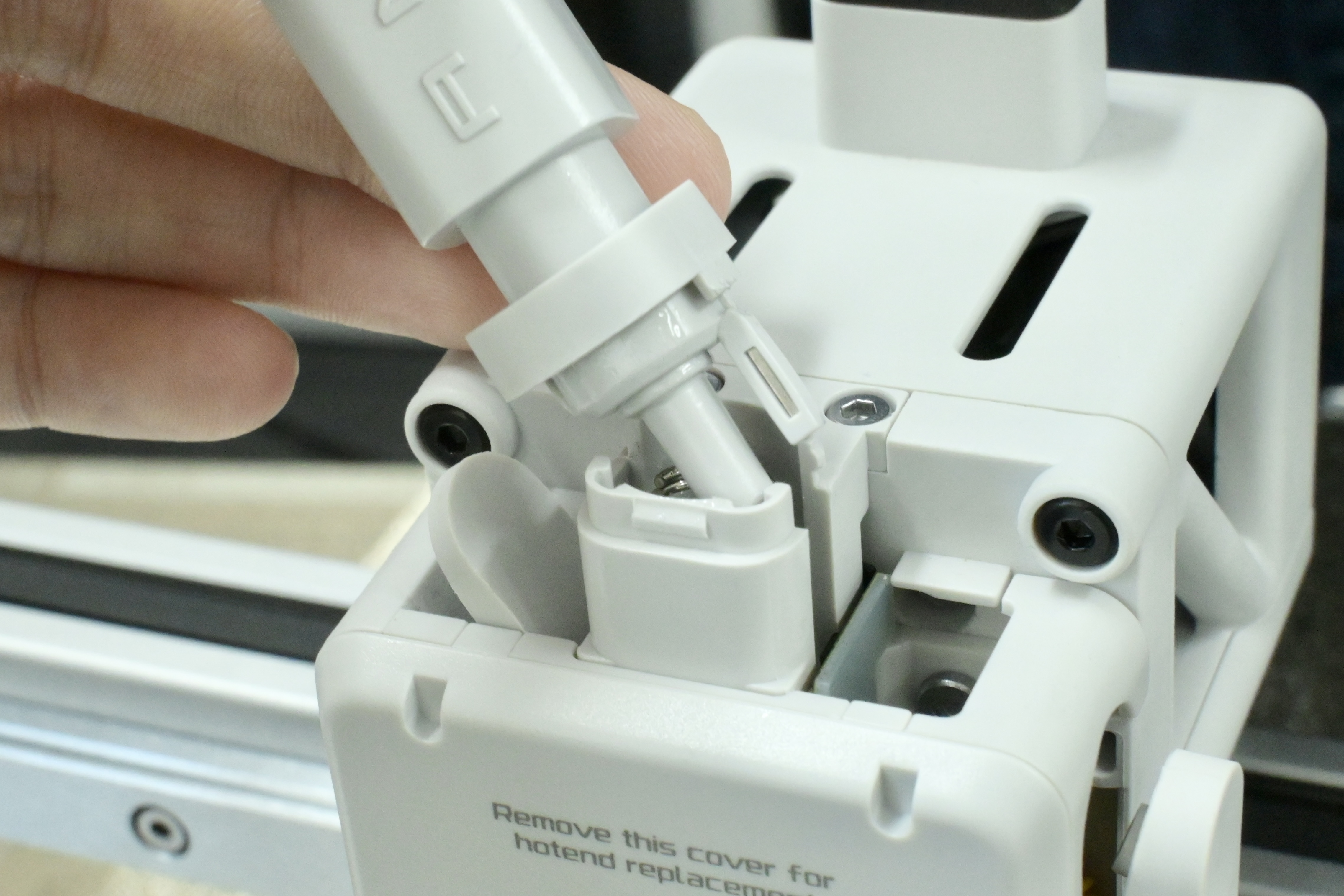
¶ Install Steel Bearing Balls
Note: Perform the following steps slowly and carefully.
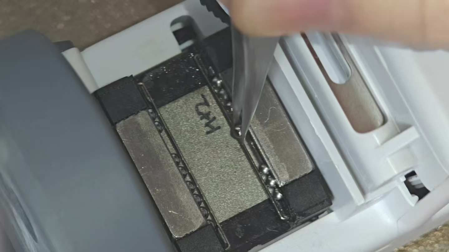
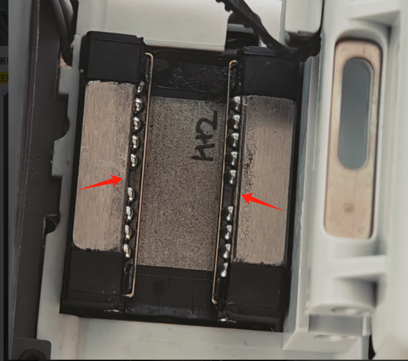
¶ Step 1: Place the steel bearing balls
Use tweezers to place the steel bearing balls into the slots.
Note: There are 24 steel bearing balls in each slot, for a total of 48 steel bearing balls. Losing 1-2 balls in a slot will not cause much damage; if more balls are lost, you will need to purchase 2.381mm diameter balls specially used for linear guideway to replace them.
 |
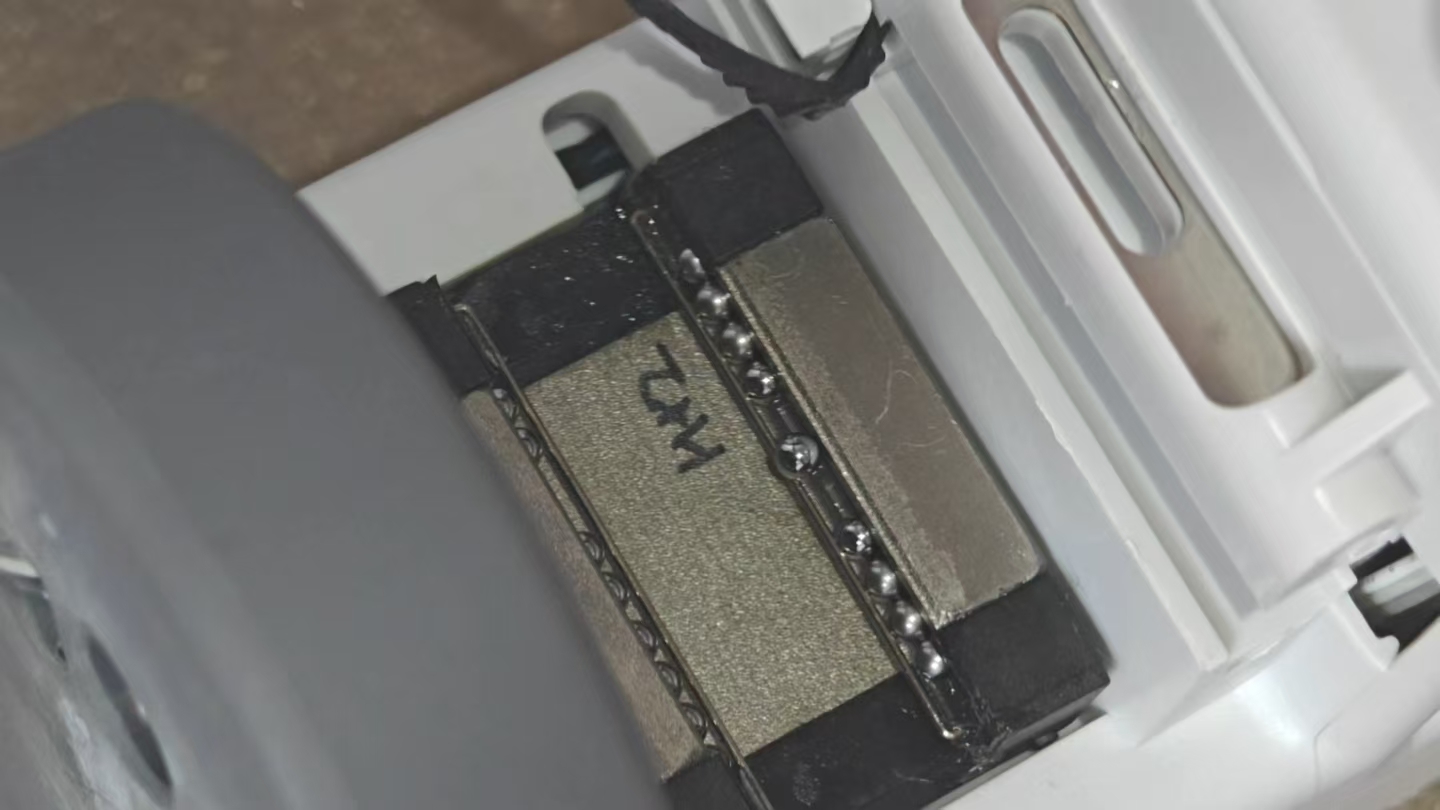 |
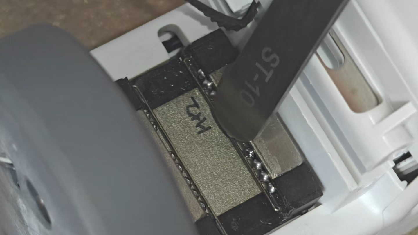
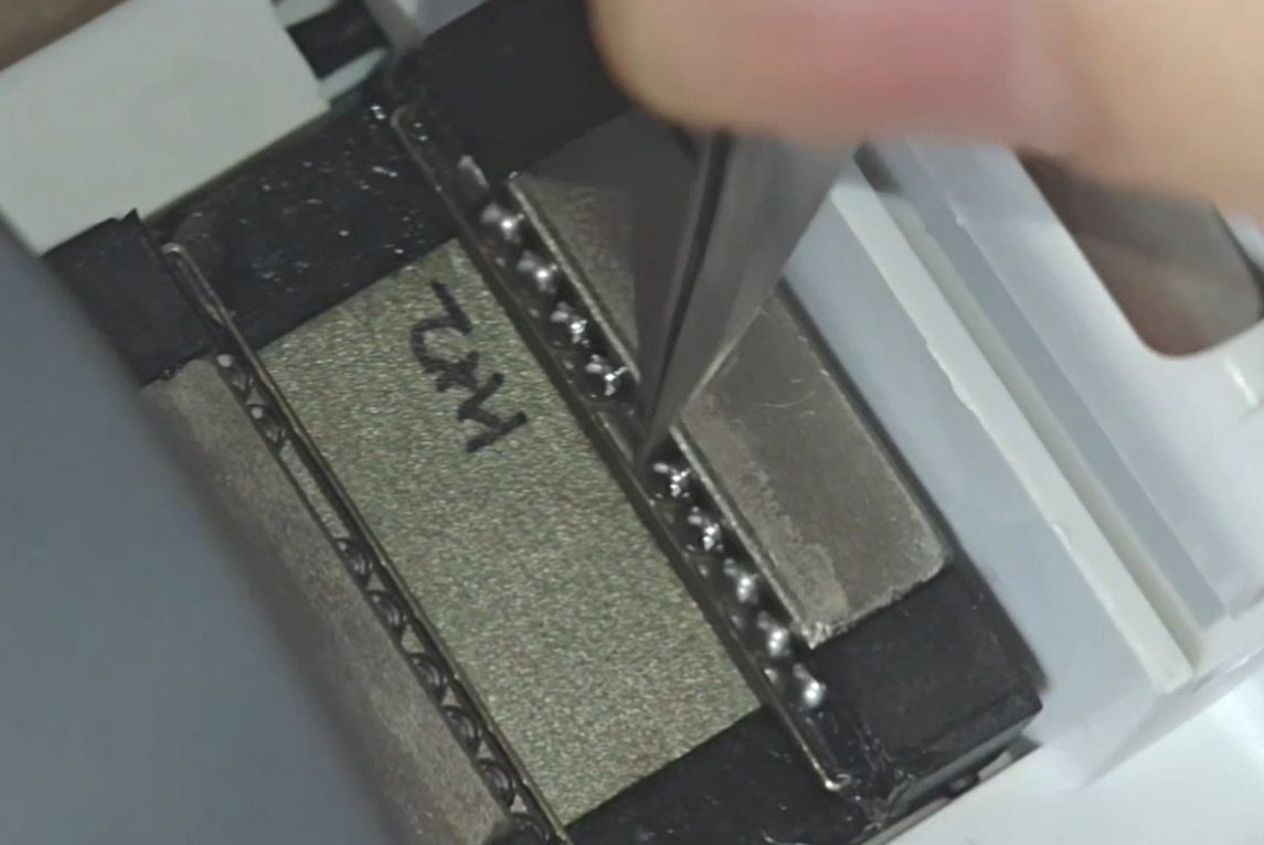
¶ Step 2: Press the steel bearing balls
Press the steel bearing balls gently into place using the back of the tweezers.
 |
 |
Repeat above steps until all the detached steel bearing balls are reinstalled.
Note: Leave space in the left and right slots to avoid filling them completely with steel bearing balls to ensure smooth movement of the slider.
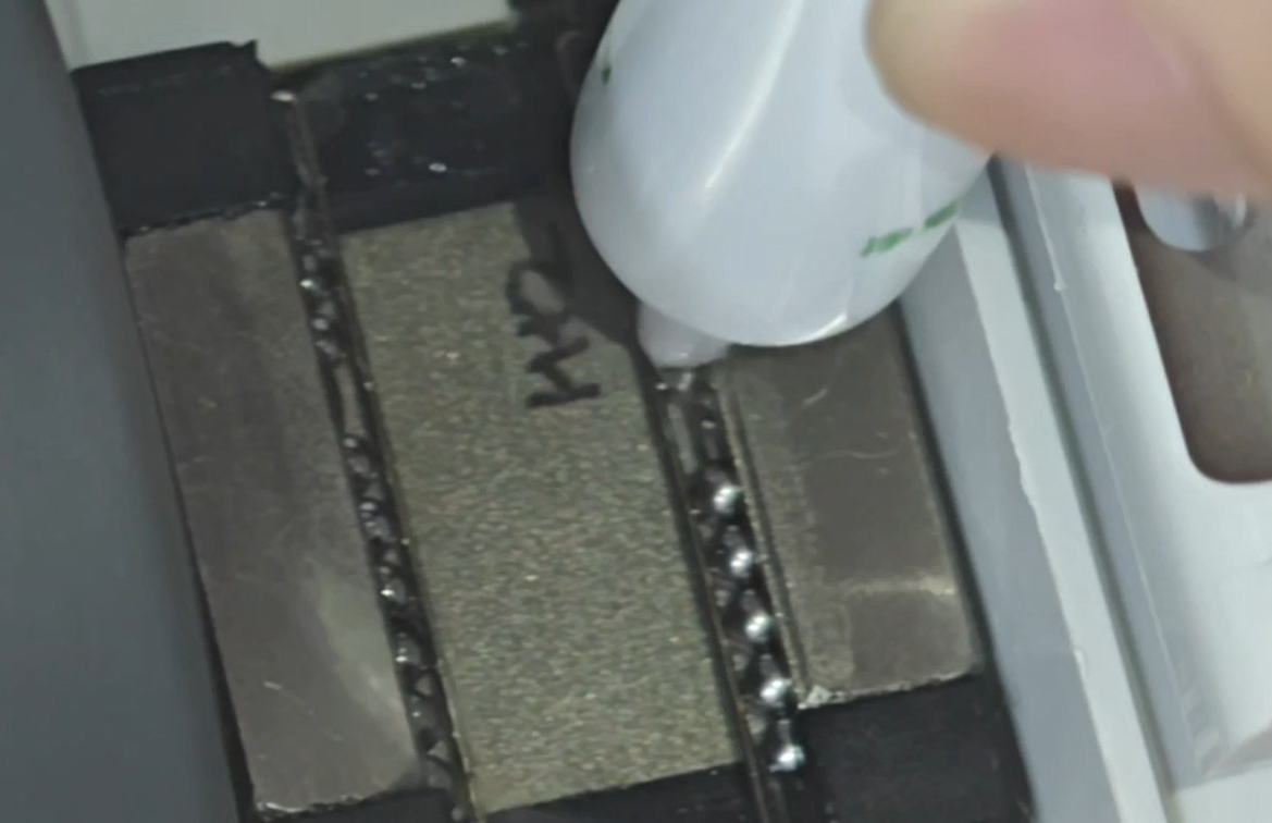
¶ Step 3: Lubricate the steel bearing balls
After installation, you can slide the steel bearing balls up and down with tweezers to ensure smooth movement; at this time, you can use lubricant oil to lubricate the steel bearing balls.
 |
 |
¶ Reinstall All Parts
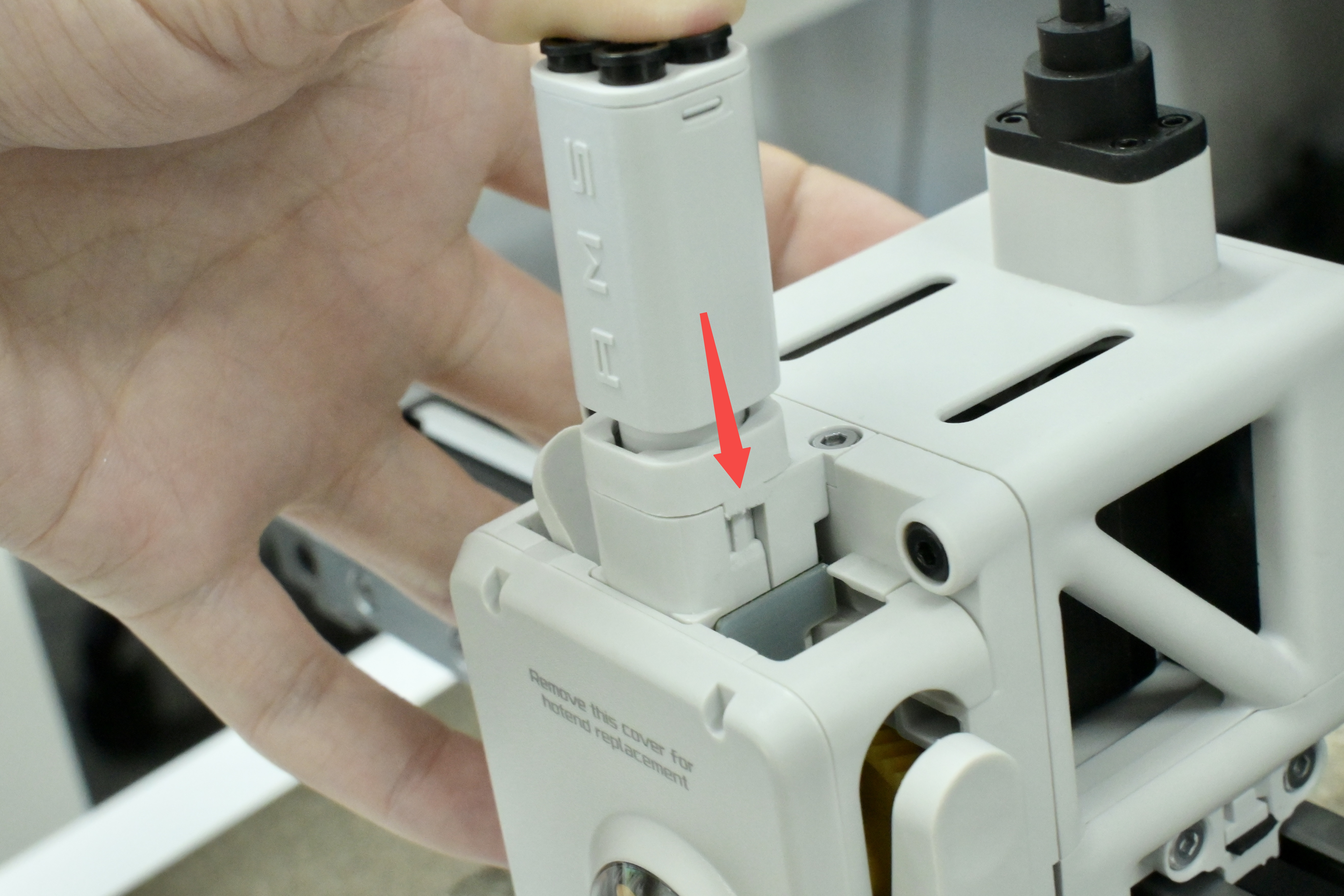
¶ Step 1: Install the toolhead
Align the upper and lower slots and slide the toolhead in. Manually slide the toolhead to see if it moves smoothly.
Note: This step needs to be performed slowly to prevent the installed steel bearing balls from falling out again.
 |
 |
¶ Step 2: Install the screws and belt block
Install the 2 screws on the left side of the X-axis belt and the 1 screw behind the toolhead; align the locating pins on the belt block and install the left belt block.
|
|
|
¶ Step 3: Install the X-axis cover
Insert the X-axis cover into X-axis, and tighten the screw.
Note: The cover screw is shorter than the purge wiper screw. If used incorrectly, the purge wiper screw will hit the X-axis idler pulley, causing abnormal X-axis resistance and continuous step loss when homing.
 |
 |
¶ Step 4: Install the purge wiper
Align the slot of the purge wiper with the bracket, slide it in until the surface is flush, then reinsert the screw into the original position and tighten it again.
 |
 |
¶ Step 5: Connect the USB-C cable
Plug in the USB-C cable and tighten the 4 screws.
¶ Step 6: Install the filament hub
Install the filament hub onto the printer. Align the mounting buckles as shown in the figure below, then press down on the bottom bracket body to lock the filament hub.
 |
 |
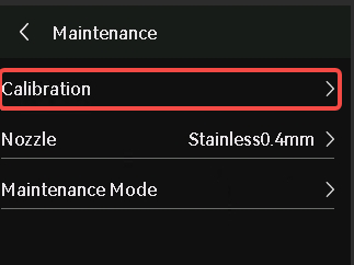
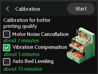
¶ Calibration
Turn on the printer, select Vibration Compensation in the Calibration menu, and complete a calibration process.
 |
 |
¶ End Notes
We hope the detailed guide provided has been helpful and informative.
If this guide does not solve your problem, please submit a technical ticket, we will answer your questions and provide assistance.
If you have any suggestions or feedback on this Wiki, please leave a message in the comment area. Thank you for your support and attention!