¶ X motor
The X motor is a stepper motor mounted on the X-axis of the printer that drives the toolhead in the X-axis.
¶ What to use?
- X motor is burned out
- After analyzing the logs, official technical support confirmed that the X motor is faulty.
¶ Safety warning
Important!
It's crucial to power off the printer before conducting any maintenance work, including work on the printer's electronics and tool head wires. Performing tasks with the printer on can result in a short circuit, leading to electronic damage and safety hazards.
During maintenance or troubleshooting, you may need to disassemble parts, including the hotend. This exposes wires and electrical components that could short circuit if they contact each other, other metal, or electronic components while the printer is still on. This can result in damage to the printer's electronics and additional issues.
Therefore, it's crucial to turn off the printer and disconnect it from the power source before conducting any maintenance. This prevents short circuits or damage to the printer's electronics, ensuring safe and effective maintenance.
For any concerns or questions about following this guide, please open a new ticket in our Support Page and we will do our best to respond promptly and provide the assistance you need.
¶ Tools and materials needed
- H2.0 hex wrench
- H1.5 hex wrench
¶ Remove X motor
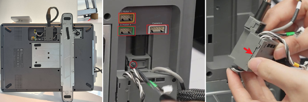
¶ Step 1: Disconnect the cables
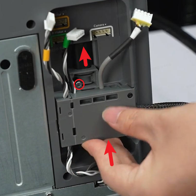
Left side down the printer to expose the cable box on the bottom, and disconnect the camera cable, X motor cable, and Z motor cable in sequence.
Loosen a silver screw and slide the cable box to disconnect the USB cable, then open the cable box and remove the Z-motor cable and X-motor cable.
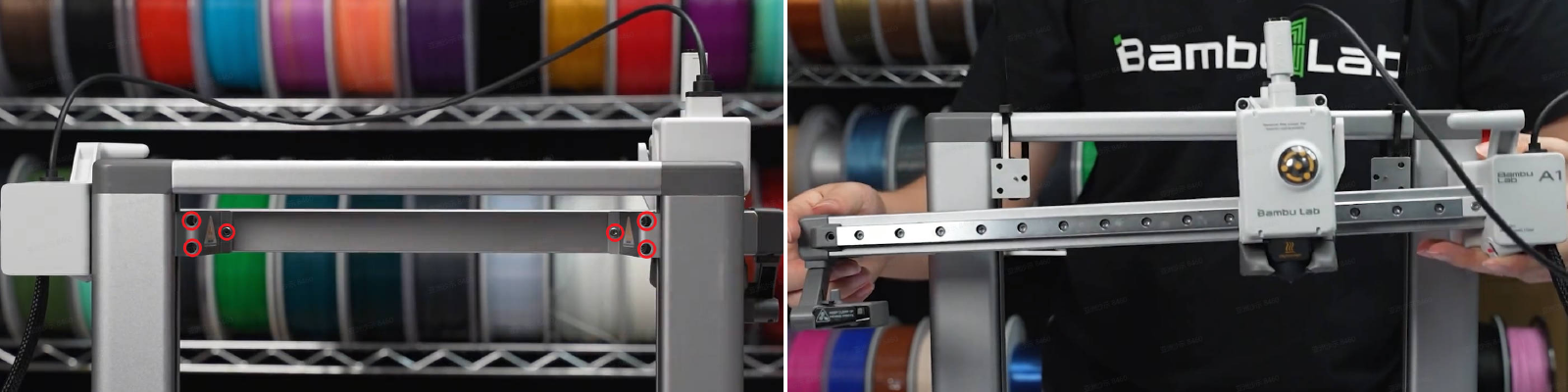
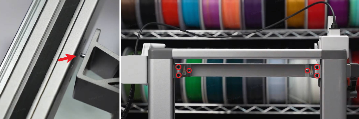
¶ Step 2: Remove the X-axis Assembly
Remove the 6 screws located at the back of the X-axis and detach the X-axis assembly from the printer frame.
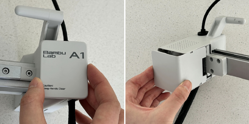
¶ Step 3: Remove the Motor Box
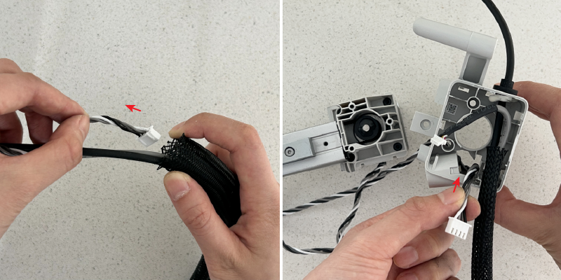
Remove the front and rear covers of the X Motor Box;
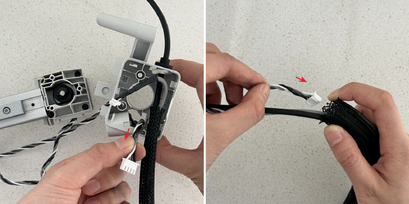
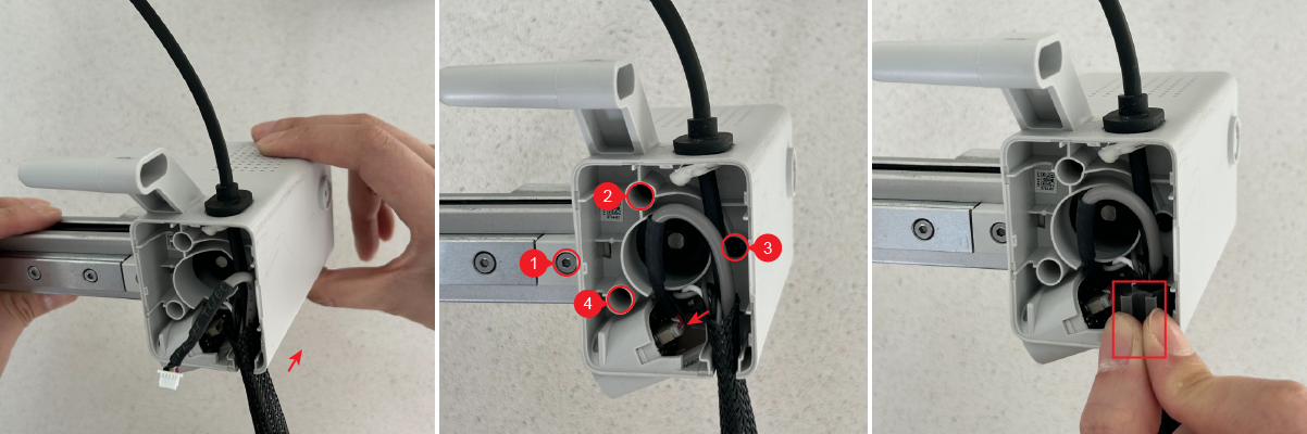
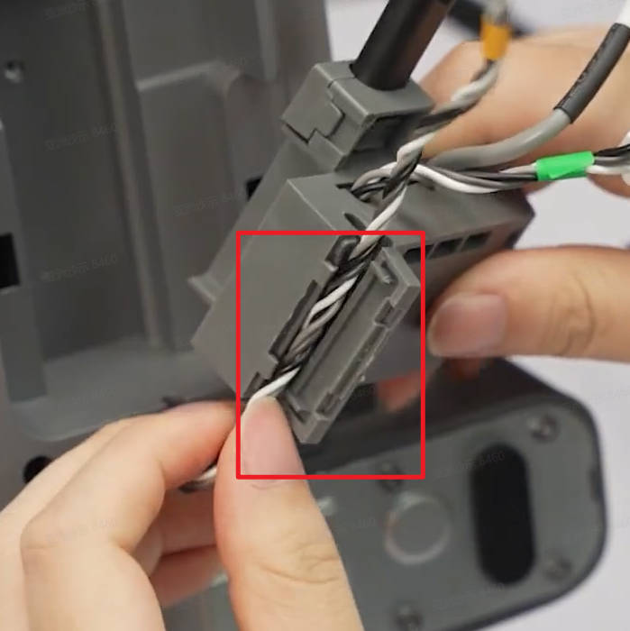
Pry out the cable clip, and disconnect the camera cable. Remove 4 screws and then slide the motor box forward to remove it;
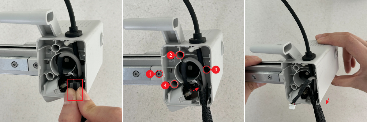
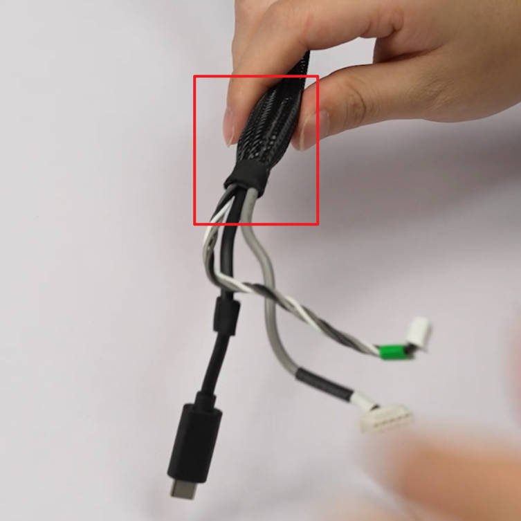
Pull the X-motor cable out of the nylon mesh tube and the motor box.
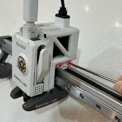
¶ Step 4: Remove the Right-Side Belt Pressing Block
Remove the 2 screws to release the right-side belt pressing block.
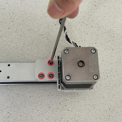
¶ Step 5: Remove the Motor Holder
Remove the 3 screws and take off the motor holder.
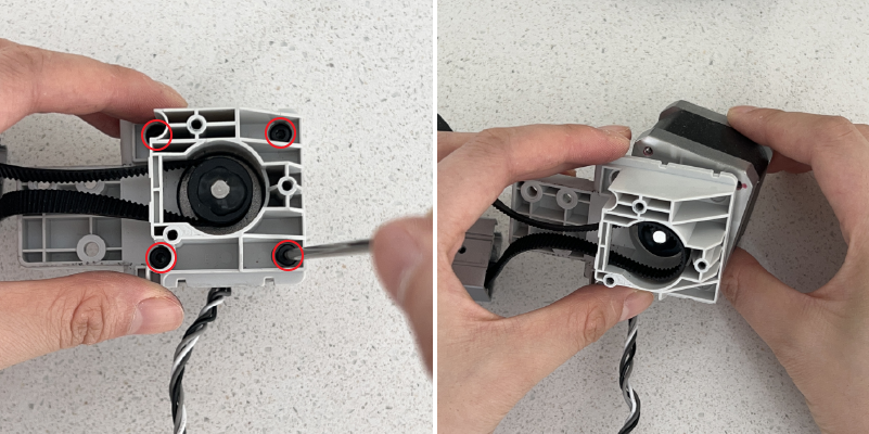
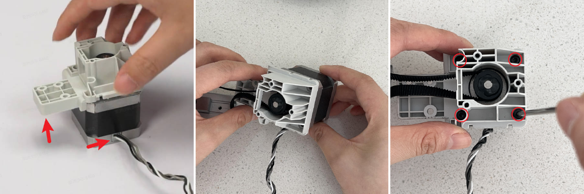
¶ Step 6: Remove the X Motor
Remove the 4 screws and take off the X motor.
¶ Assembly Guide
¶ Step 1: Install the X Motor
Check the direction of the X Motor cable. Pass the X motor pulley through the X-axis belt, then install the motor onto the motor holder, and secure it with 4 screws.
¶ Step 2: Install the X Motor Holder
Mount the motor holder onto the X-axis, and secure it with 3 screws.
¶ Step 3: Install the Right-Side Belt Pressing Block
Install the right-side belt pressing block onto the toolhead, and secure it with 2 screws.
¶ Step 4: Install the Motor Box
Pass the X motor cable through the motor cover and the nylon mesh tube;
Mount the motor box onto the holder and secure it with 4 screws. Connect the camera cable and install the cable clip;
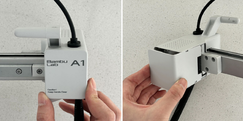
Install the front and rear covers of the X Motor Box.
¶ Step 5: Install X-axis Assembly
Align the X-axis with the locating pins on the two Z-axis sliders, then install it onto the Z-axis sliders. Finally, secure the X-axis assembly by tightening 3 screws on each side.
¶ Step 6: Connect the Cables
Secure the nylon mesh tube with tape, and organize the cables;
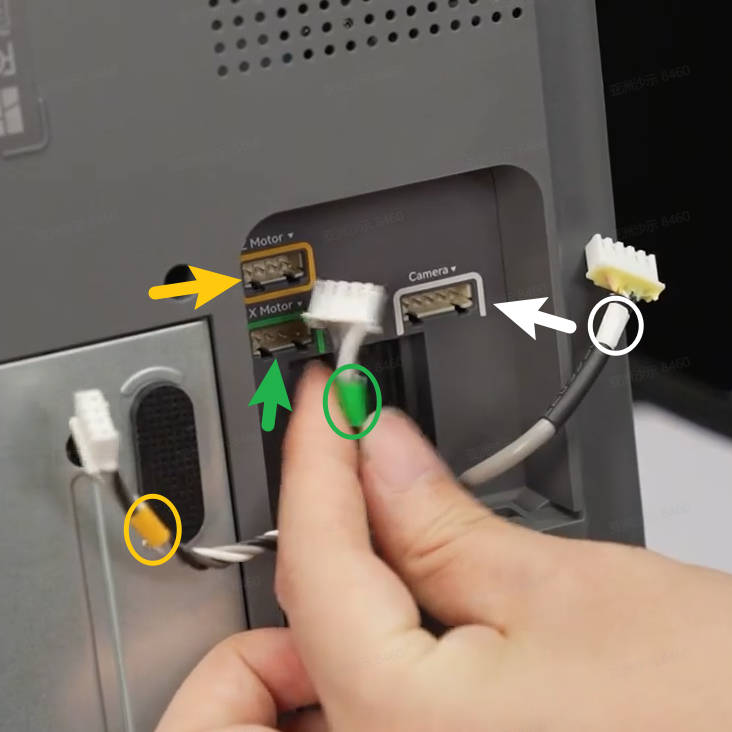
Place the printer in a backward position, connect the X-motor cable and Z-motor cable to the cable management box;
Install the cable management box onto the bottom base, slide it along the slot direction, connect the USB cable, and tighten 1 silver screw;
Follow the text prompts and color labels to connect the X motor cable, Z motor cable, and camera cable. Organize the cables properly and ensure they are not being pressed or tangled. Set the printer upright.
¶ Functionality Verification and Calibration Step
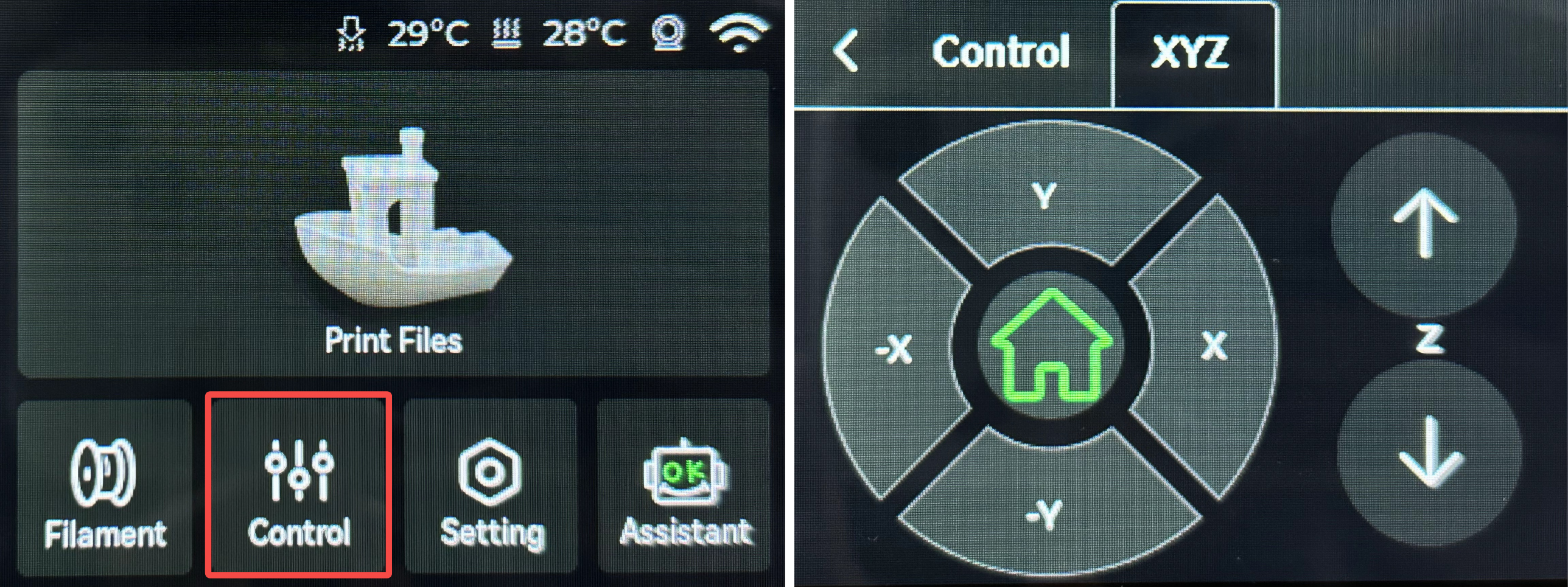
After completing all the assembly steps above, power on the printer, enter the control interface, and click the "-X" or "X" button on the screen to move the X-axis and confirm whether the X motor is functioning properly.
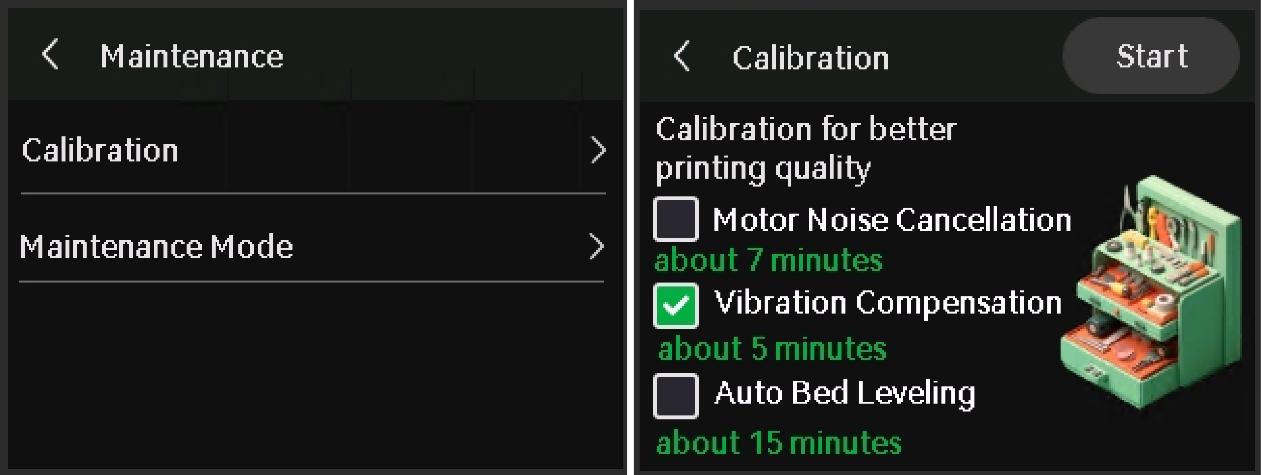
In the Calibration screen, select only Vibration Compensation, and then tap Start.
The calibration will confirm the printer is running as expected.
¶ End Notes
We hope the detailed guide provided has been helpful and informative.
To ensure a safe and effective execution, if you have any concerns or questions about the process described in this article, we recommend submitting a technical ticket regarding your issue.
Please include a picture or video illustrating the problem, as well as any additional information related to your inquiry.