¶ Y Motor
The Y motor is a stepper motor mounted on the Y-axis of the printer that drives the heatbed in the Y-axis.
¶ When to Use?
- Y motor is burned out
- After analyzing the logs, official technical support confirmed that the Y motor is faulty.
¶ Safety warning
Important!
It's crucial to power off the printer before conducting any maintenance work, including work on the printer's electronics and tool head wires. Performing tasks with the printer on can result in a short circuit, leading to electronic damage and safety hazards.
During maintenance or troubleshooting, you may need to disassemble parts, including the hotend. This exposes wires and electrical components that could short circuit if they contact each other, other metal, or electronic components while the printer is still on. This can result in damage to the printer's electronics and additional issues.
Therefore, it's crucial to turn off the printer and disconnect it from the power source before conducting any maintenance. This prevents short circuits or damage to the printer's electronics, ensuring safe and effective maintenance.
For any concerns or questions about following this guide, please open a new ticket in our Support Page and we will do our best to respond promptly and provide the assistance you need.
¶ Tools and materials needed
- H2.0 hex wrench
- H1.5 hex wrench
¶ Disassemble Y Motor
¶ Step 1: Remove the baseplate
Tilt the screen to one side and lower the X-axis to the bottom, then gently place the printer face down as shown below. It is recommended to use a box of filament to prop up the top to avoid putting pressure on the extruder and screen.
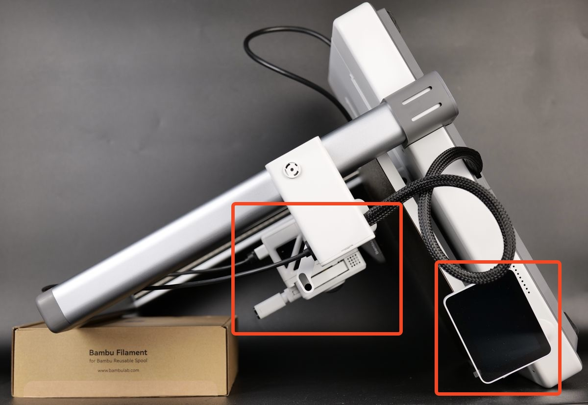
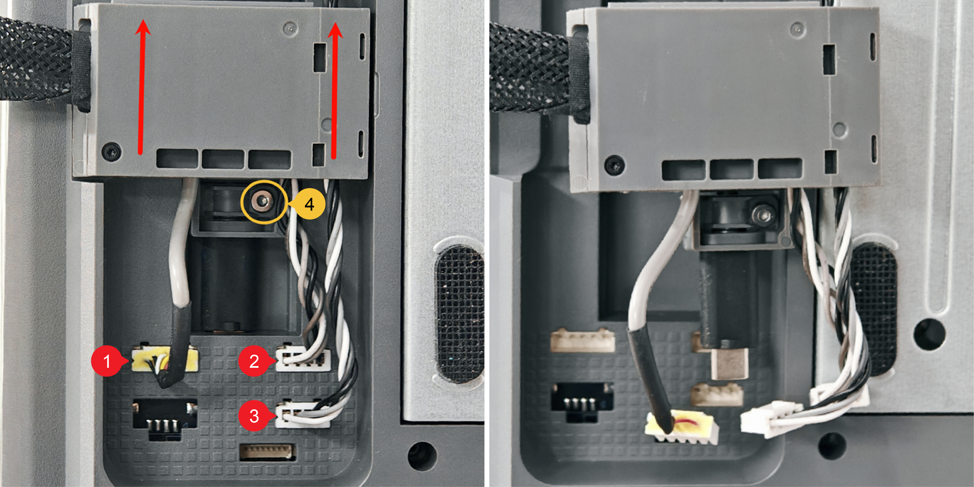
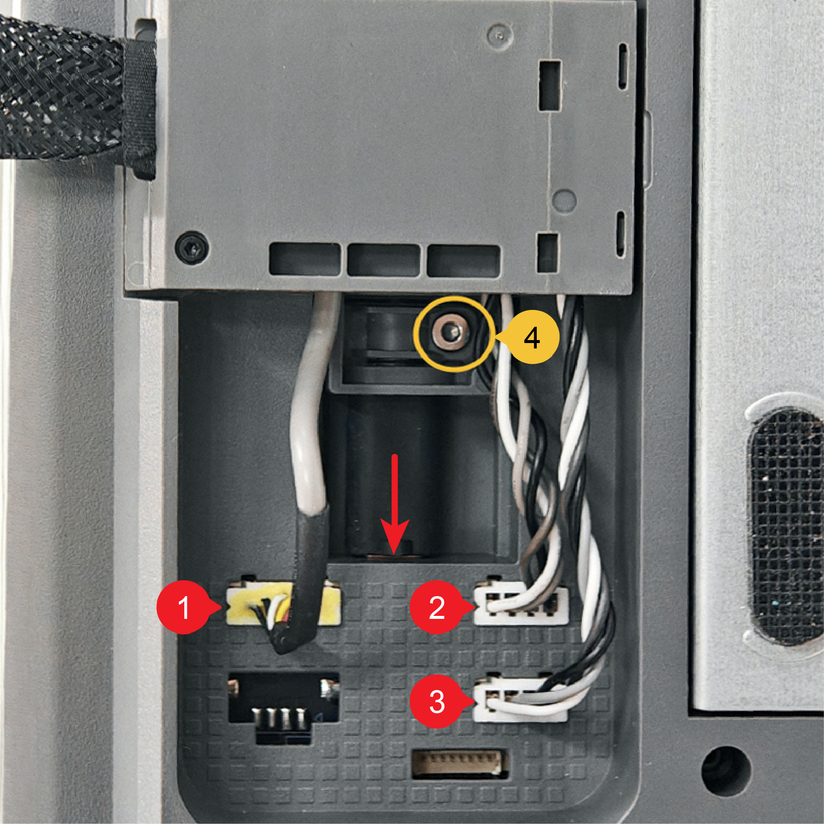
Loosen the screw marked in yellow without fully removing it.
Disconnect cables 1, 2, and 3, which correspond to the camera, Z-axis motor, and X-axis motor respectively. Then push the cable bracket upward to disconnect the USB-C cable.
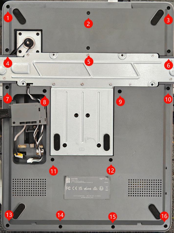
Remove the 16 screws from the bottom, then take off the baseplate.
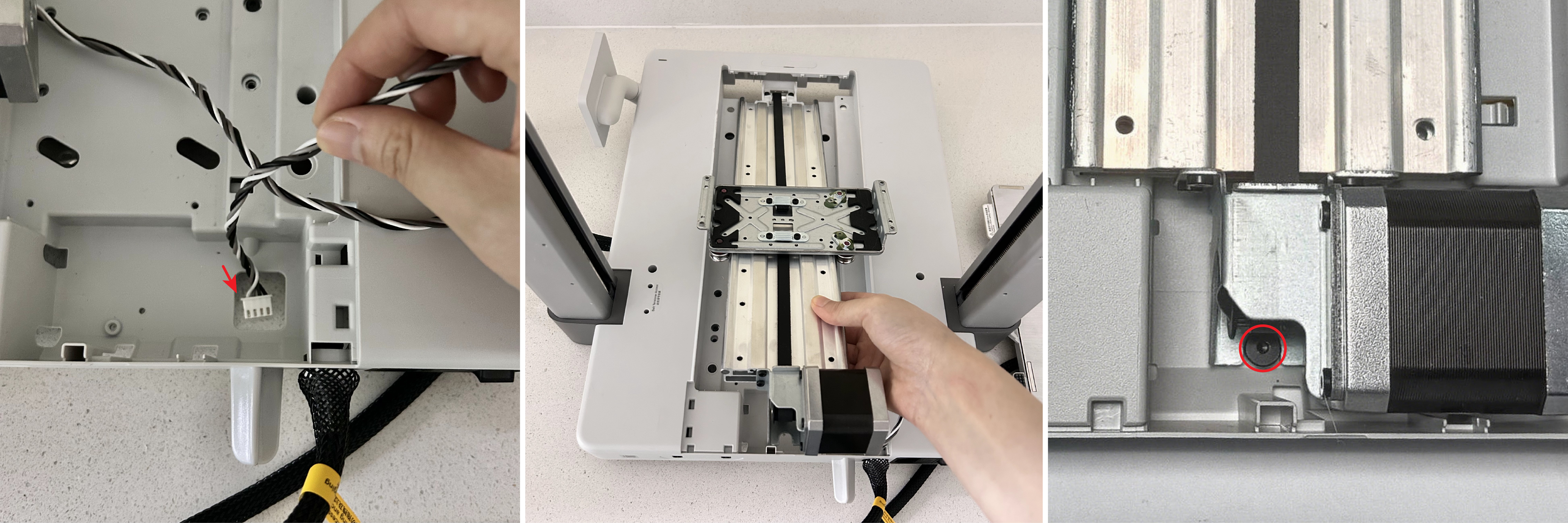
¶ Step 2: Disconnect the cables
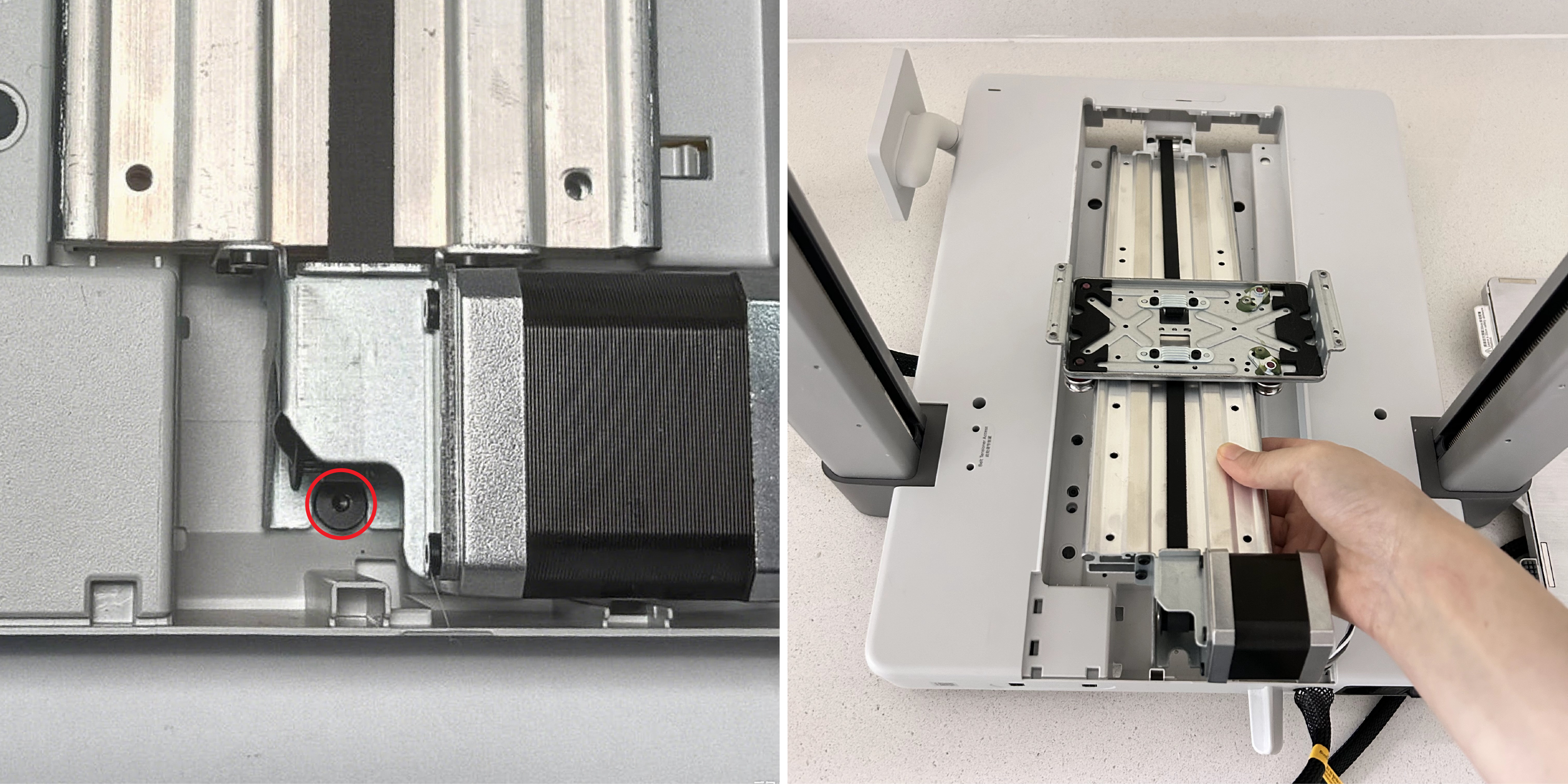
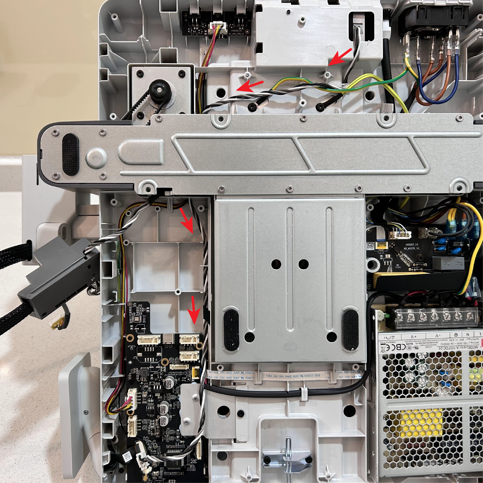
Remove the fixing screw for the heat sink and the Y motor connector.
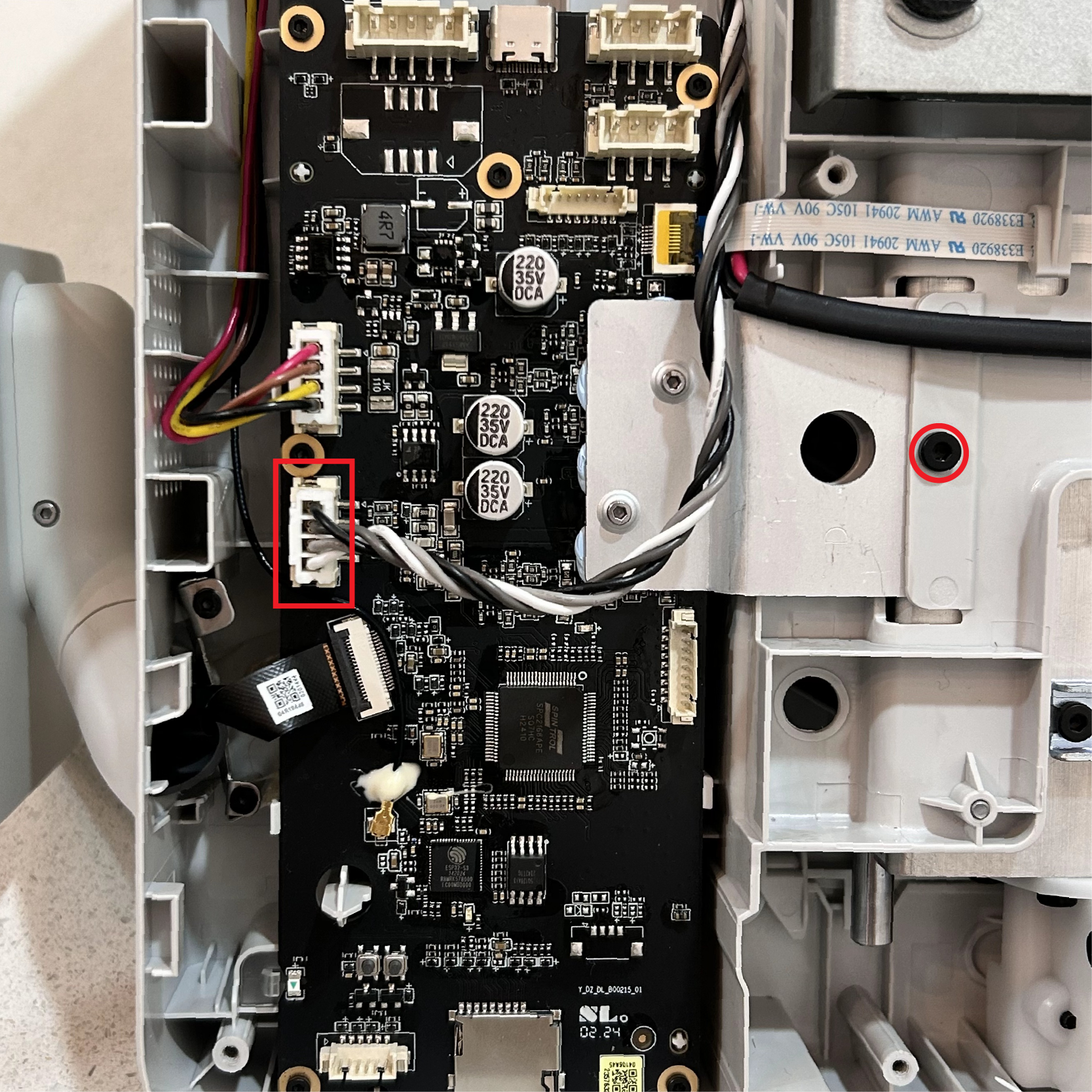
Release the Y motor cable from the cable channel and clips.
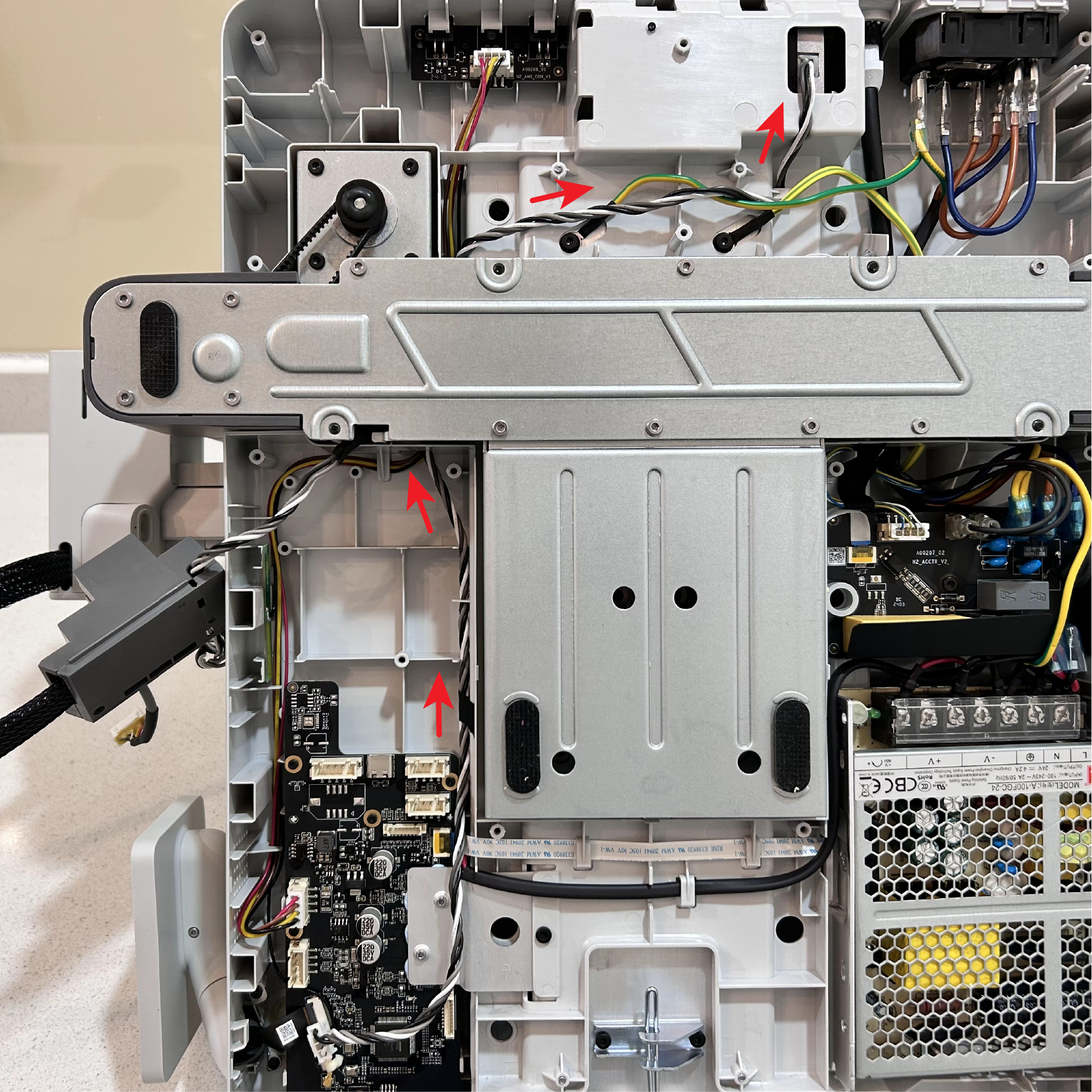
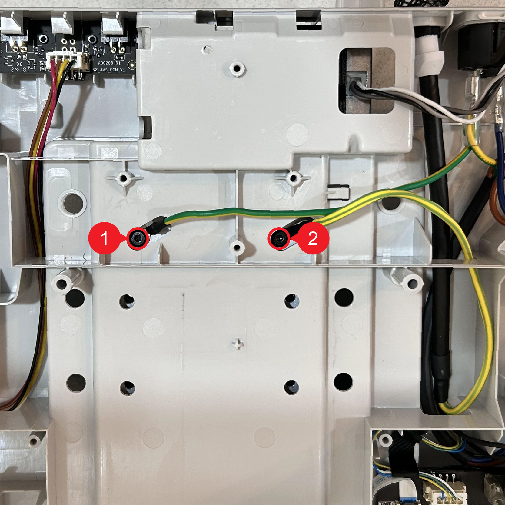
Remove two fixing screws on the ground cable.
¶ Step 3: Remove the heatbed
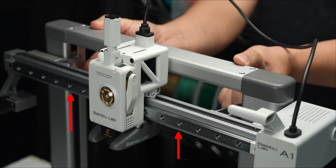
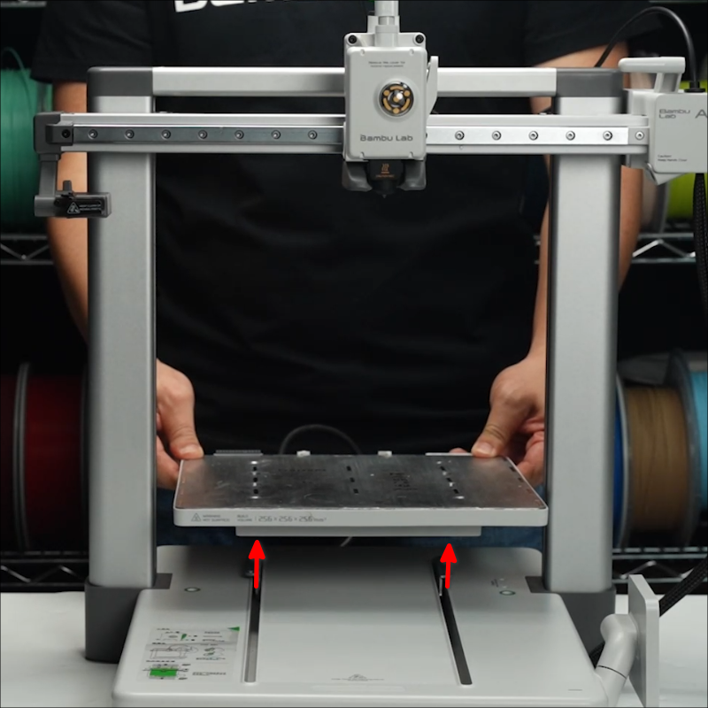
Place the printer on a flat surface and slowly raise the X-axis to the top.
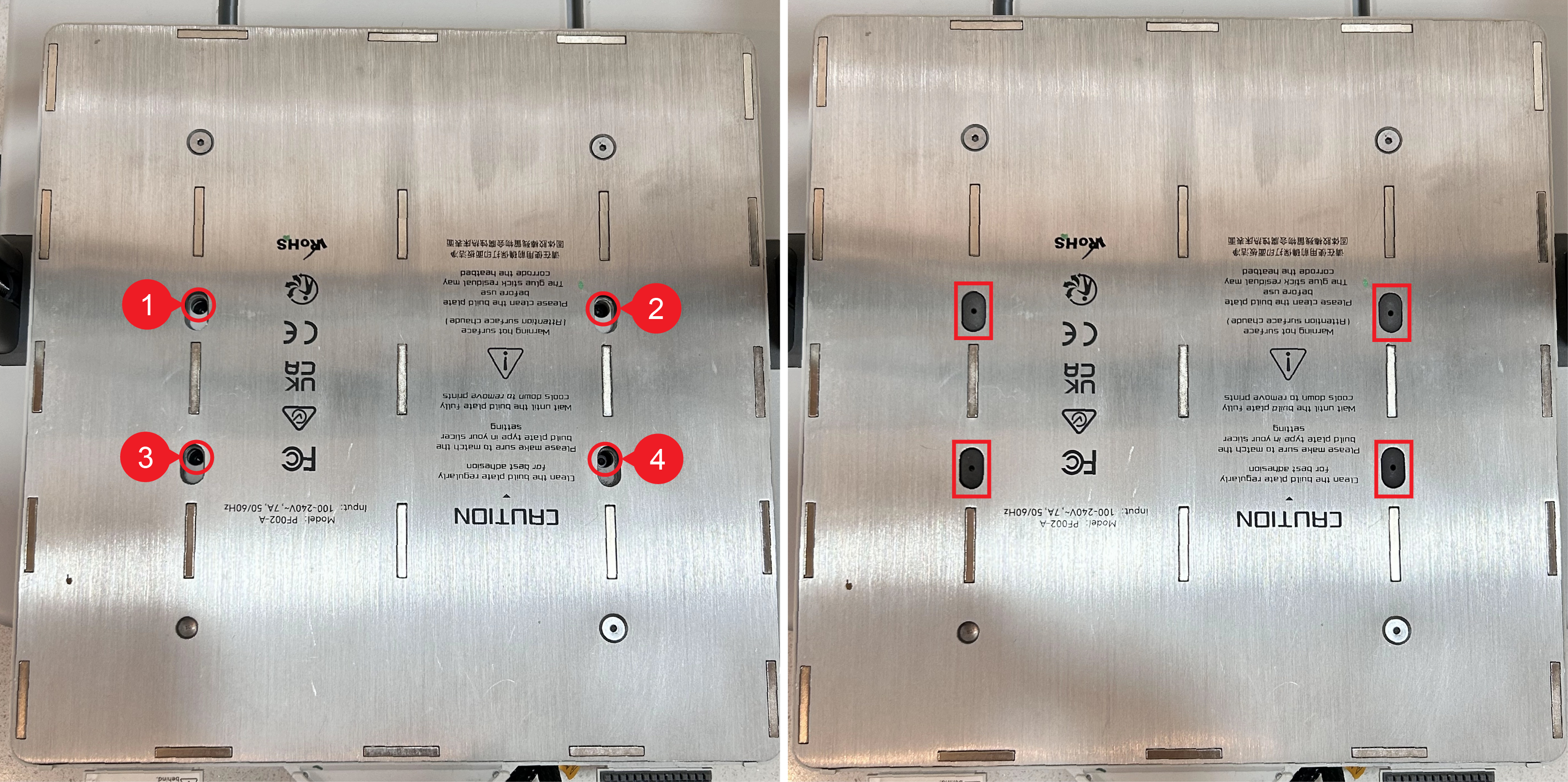
Remove the 4 soft silicone sleeves, then remove the 4 screws that fix the heatbed.
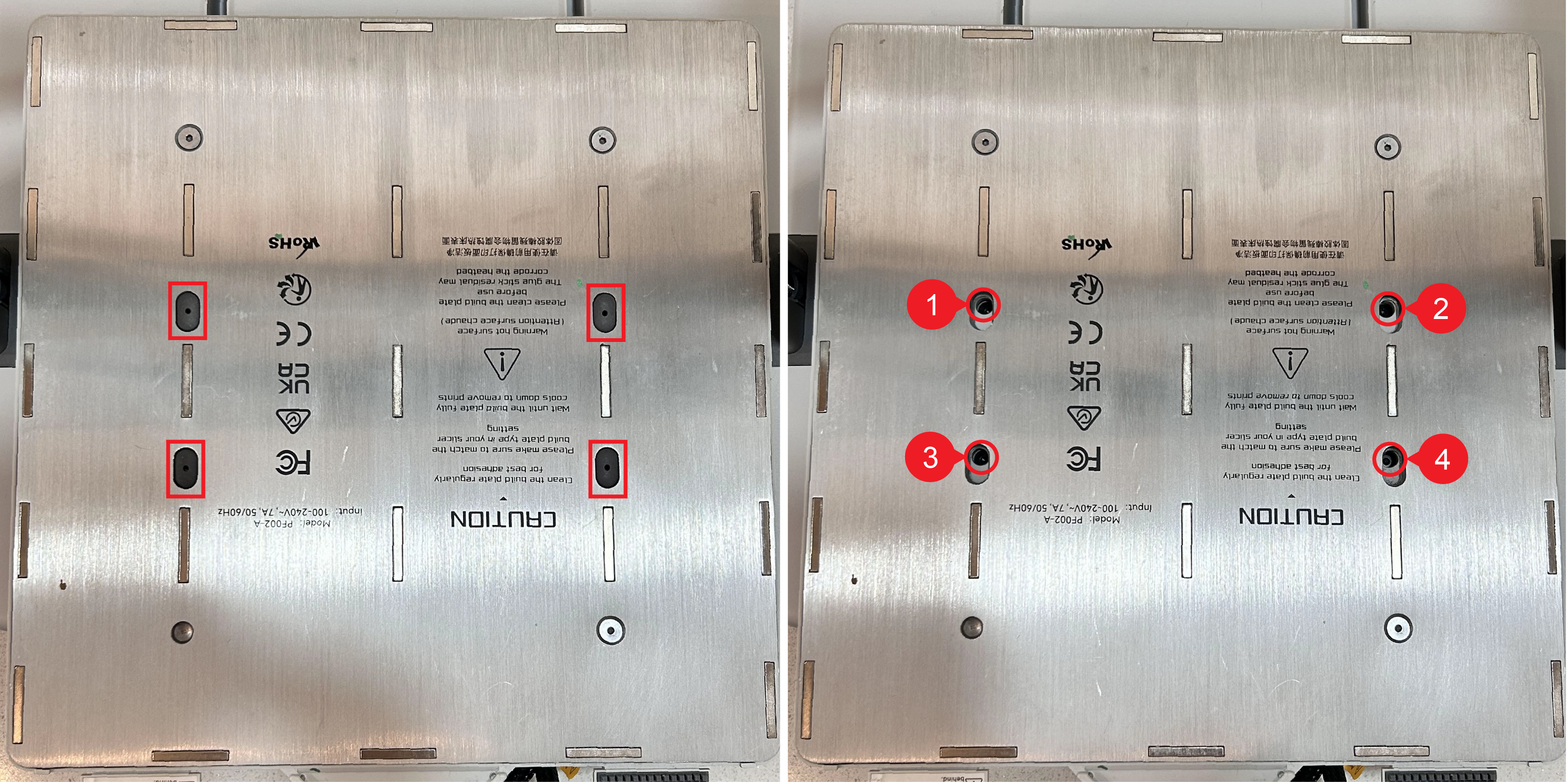
Note:The latest version of the heatbed no longer includes silicone sleeves.
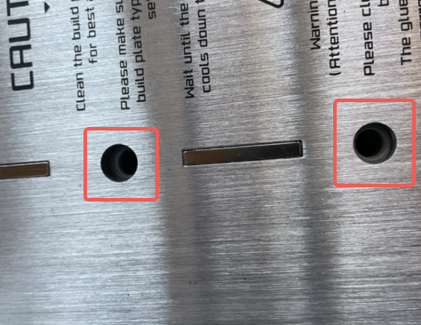
Remove the heatbed from the base and place it on the table.
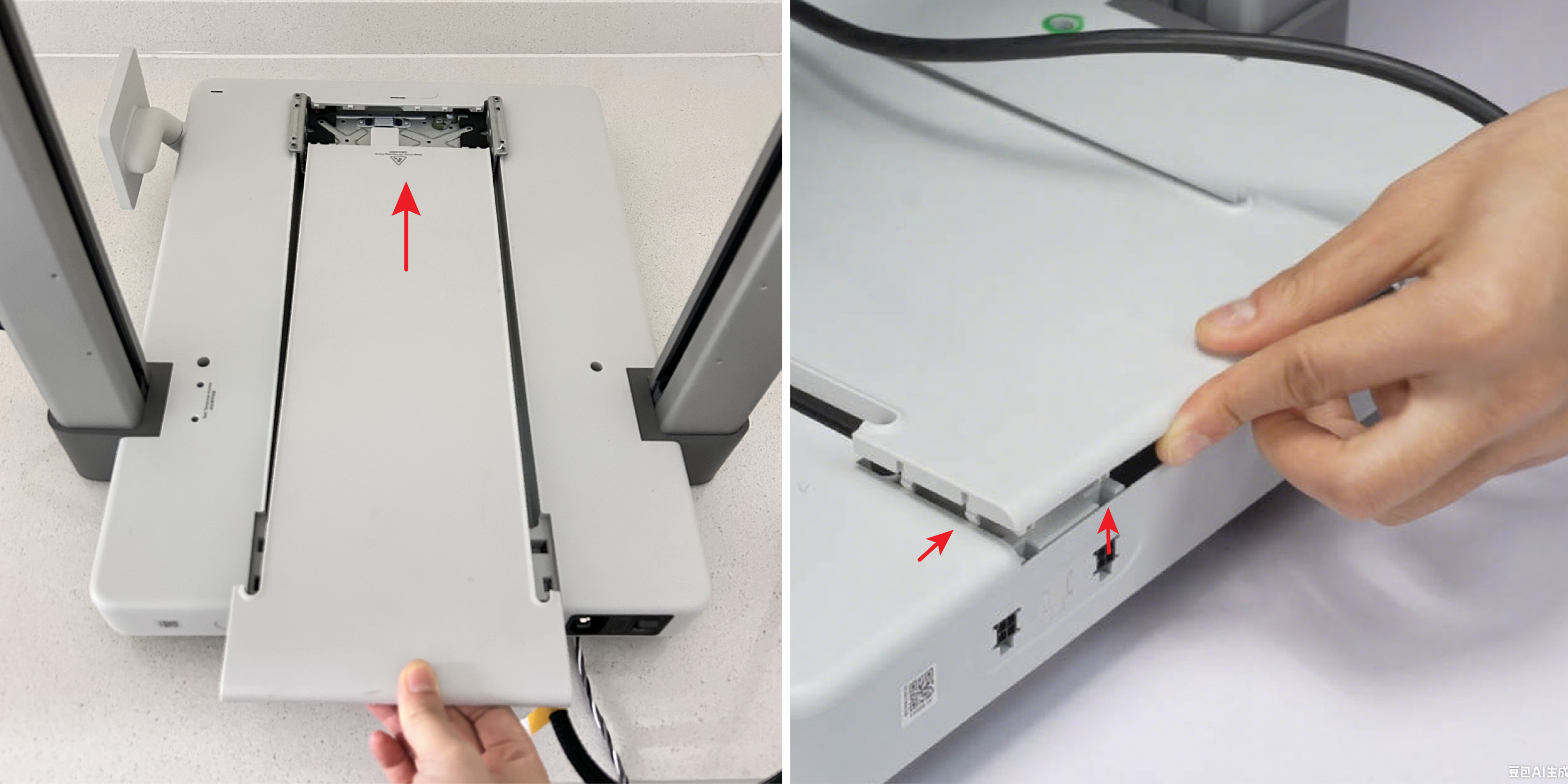
¶ Step 4: Remove the Y-axis cover
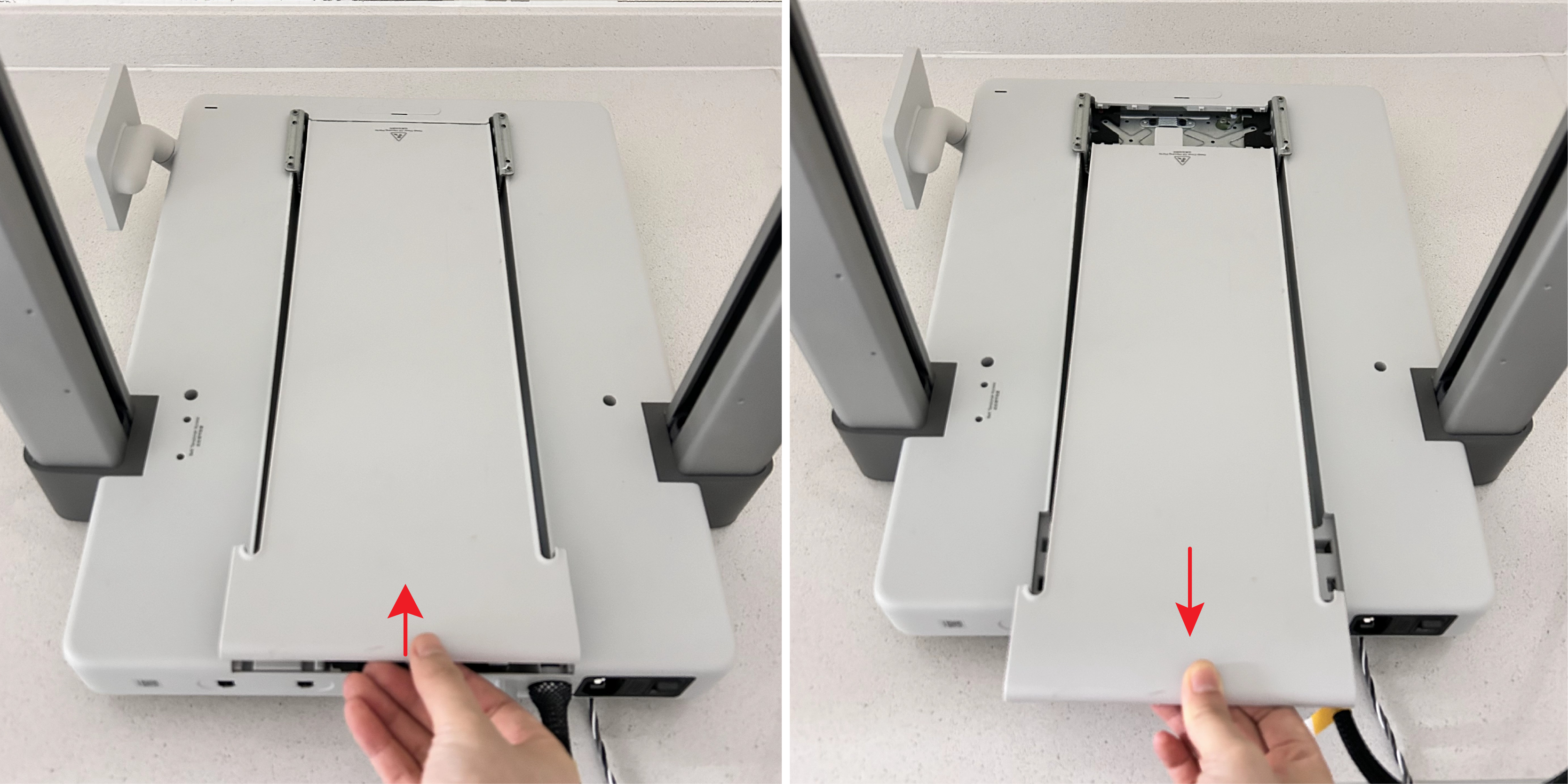
Lift the rear end of the Y-axis cover upward, then slide it horizontally to remove.
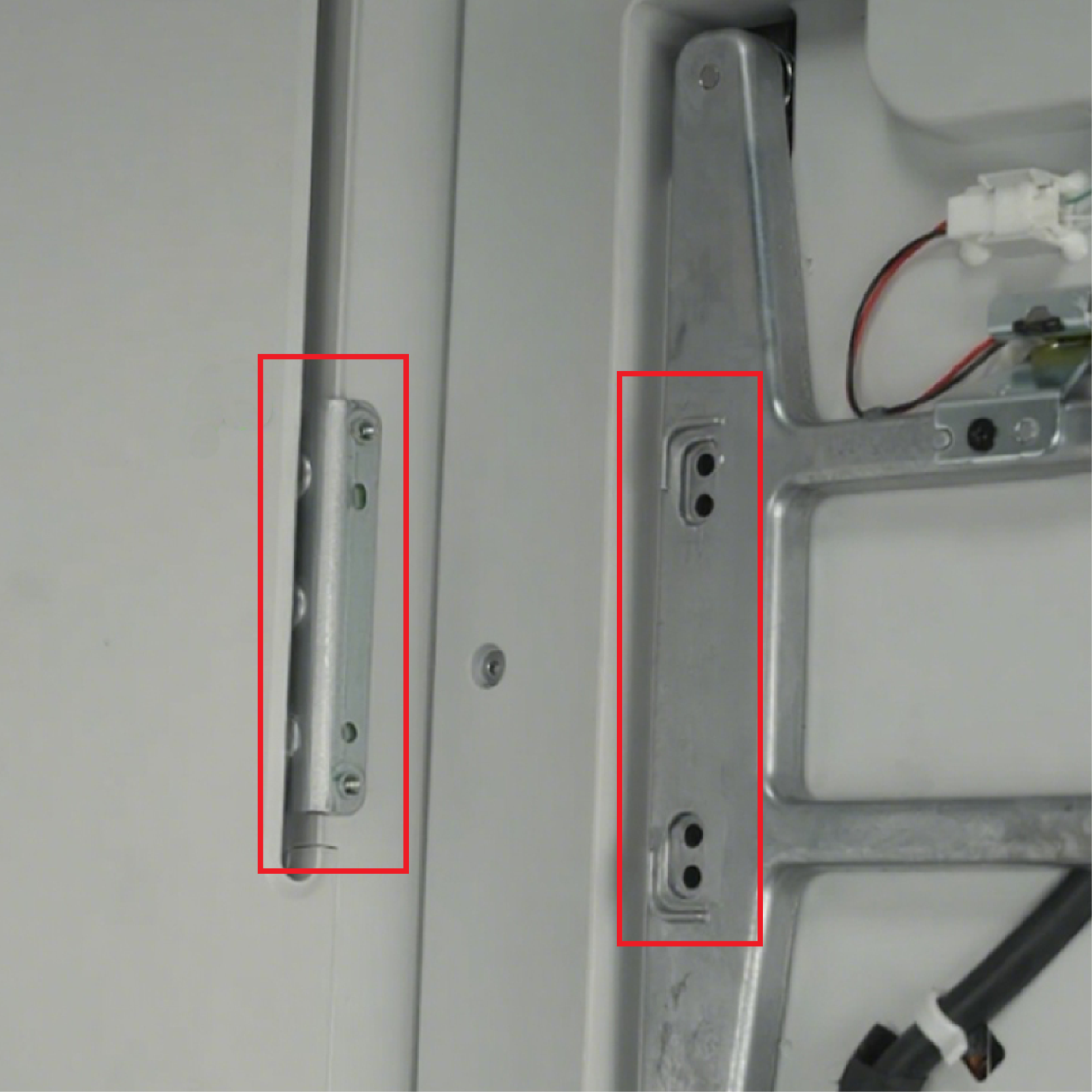
¶ Step 5: Remove the Y-axis linear guide assembly
Move the Y-axis slide block to the front end, remove the 8 red-marked screws and 2 yellow-marked screws.
After the screws are removed, move the pulley to the tail end and then remove the 2 yellow-marked screws at the front end.
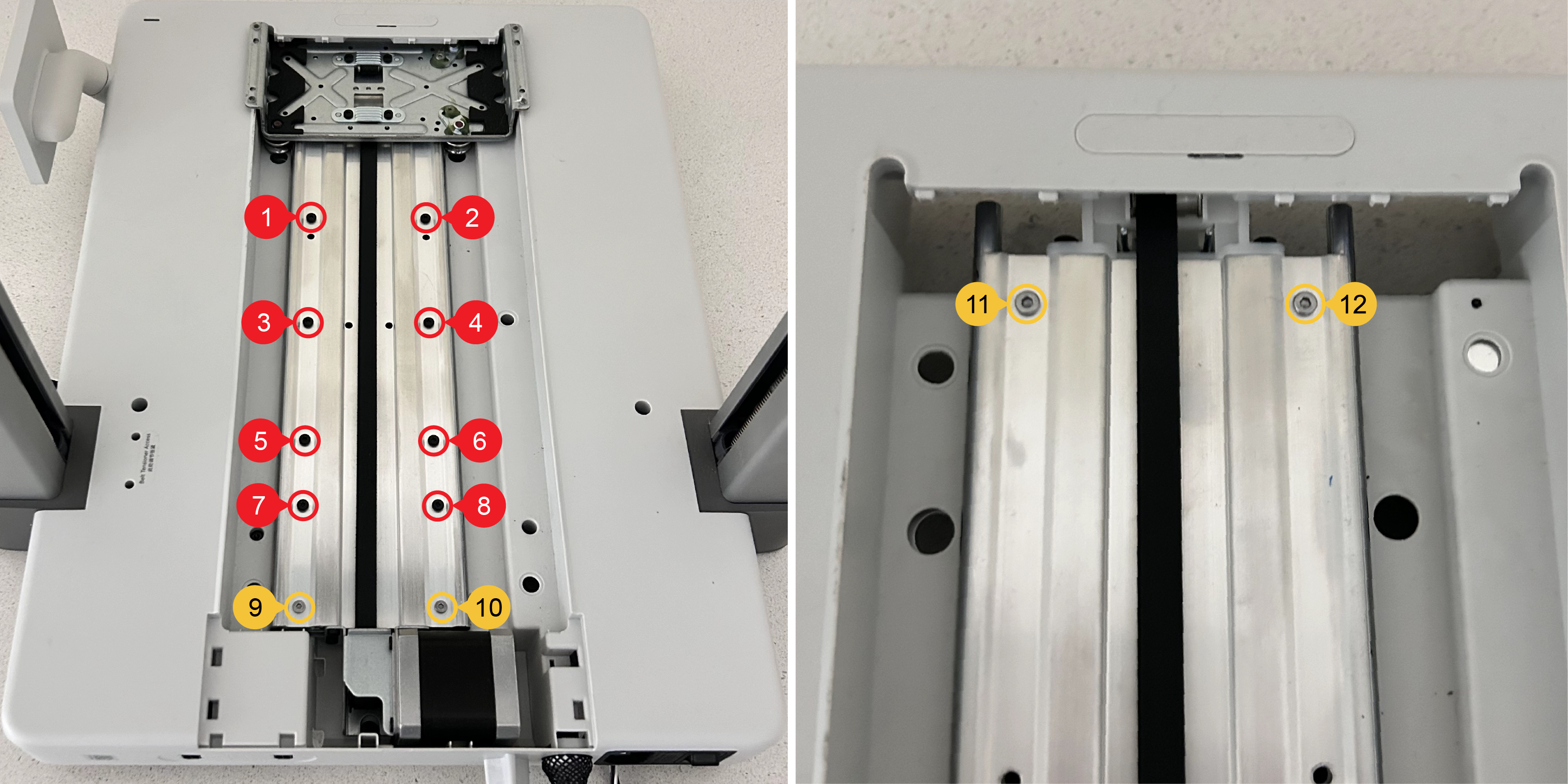
Remove 1 motor mounting screw and take off the Y-axis Linear Guide Assembly.
¶ Step 6: Loosen the Y-axis belt
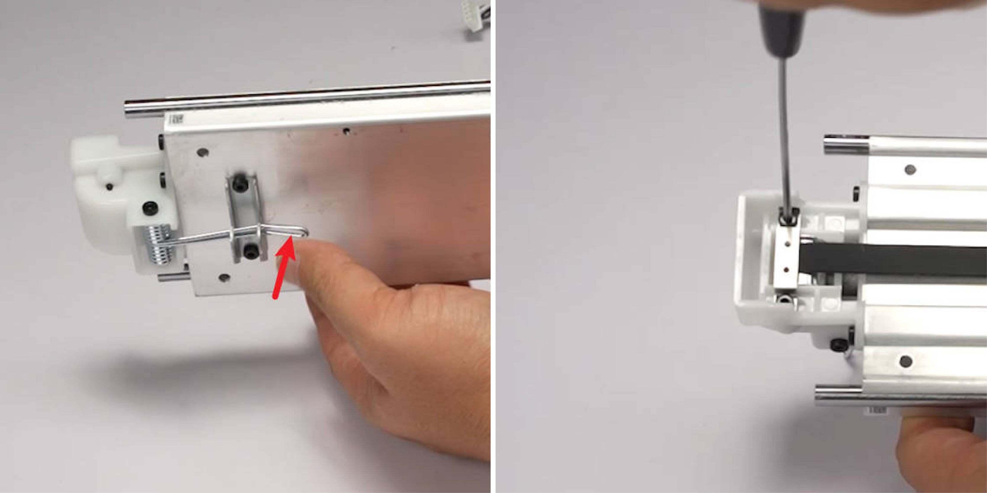
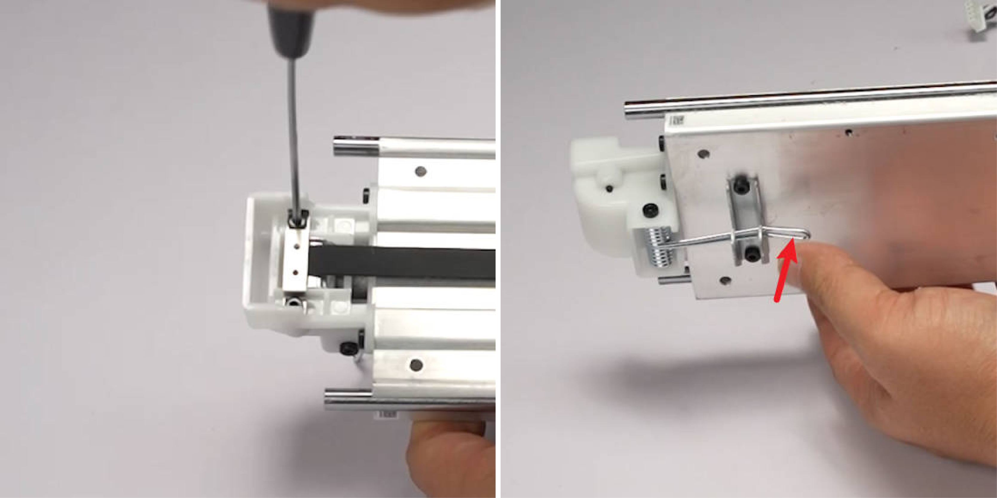
Release the Y-axis belt tension spring and loosen the 2 tensioner screws by 1 turn each.
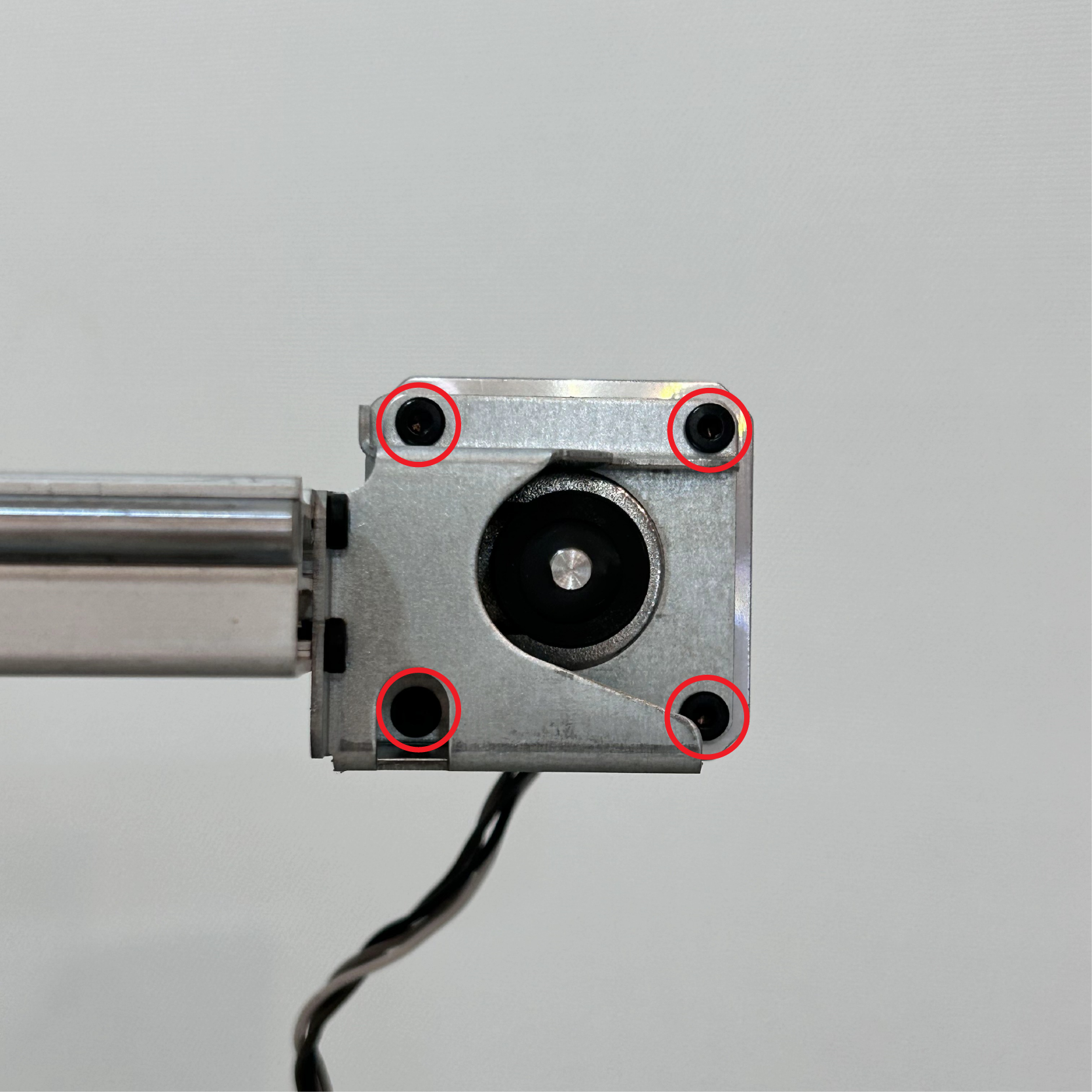
¶ Step 7: Remove Y motor
Remove 4 screws and take off the Y motor.
¶ Assemble the Y motor
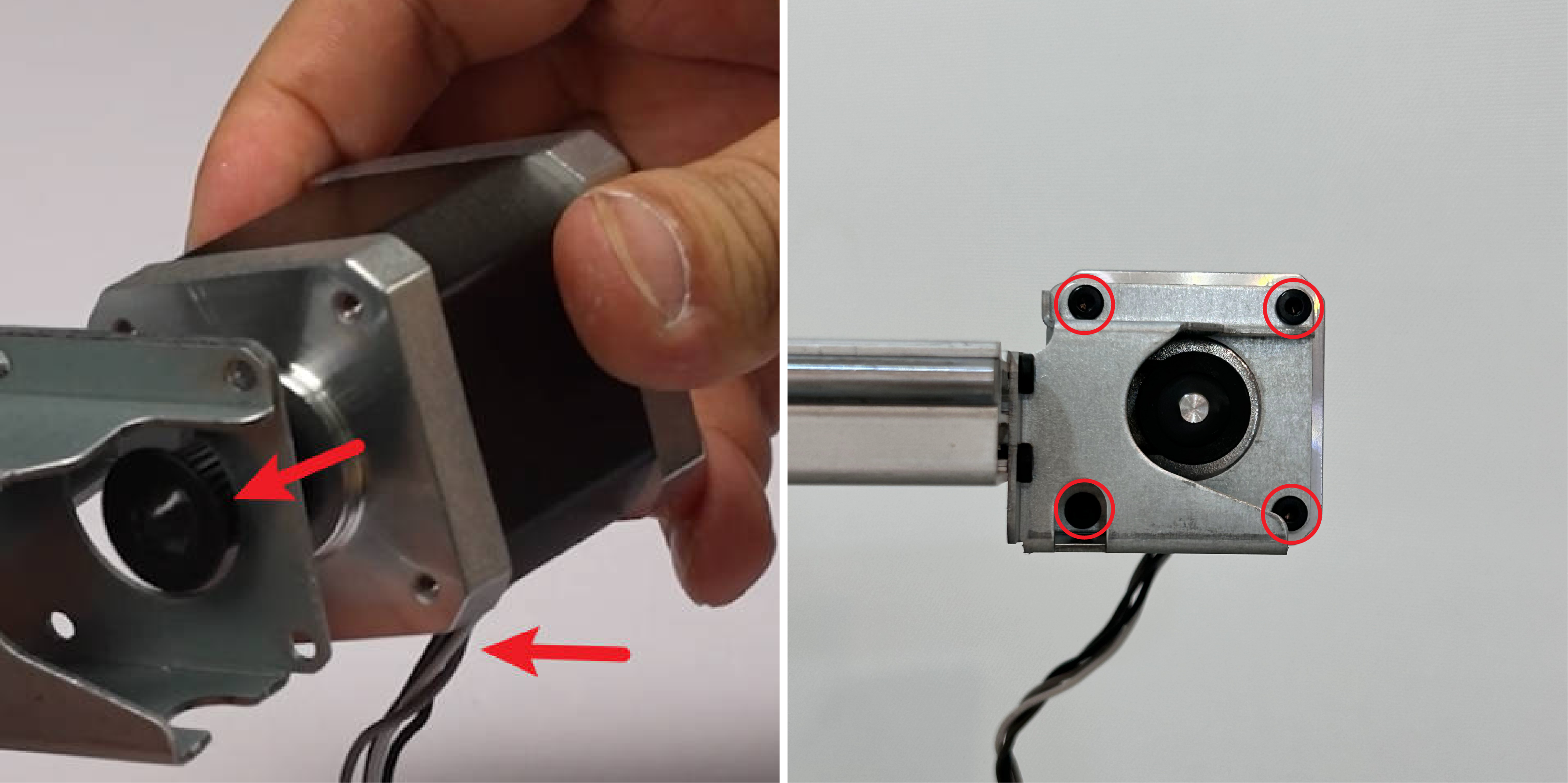
¶ Step 1: Assemble the Y motor
Ensure the Y motor cable faces downward. After threading the Y motor pulley through the Y belt, mount it onto the motor bracket and secure it with 4 screws.
¶ Step 2: Tighten the Y-axis belt
Tighten the 2 tensioner screws by 1 turn each, then secure the Y-axis belt tension spring.
¶ Step 3: Install the Y-axis linear guide assembly
Thread the Y motor cable through the baseplate.
First, insert the Y tensioner end into the base, then position the Y motor end and secure it with 1 screw on the Y motor bracket.
Secure the Y-axis linear guide assembly with 12 screws.
¶ Step 4: Install the Y-axis cover
Slide the Y-axis cover forward horizontally, align the clips, and secure the cover in place.
¶ Step 5: Install the heatbed
Align the installation position and place the heatbed onto the heatbed bracket.
Secure the heatbed with 4 screws and install 4 soft silicone sleeves.
¶ Step 6: Connect the cables
Place the printer face down.
Thread the Y motor cable.
Connect the Y motor cable to the mainboard, then secure the mainboard heatsink to the Y-axis rail with 1 screw.
Secure the power ground cable with 2 screws and organize the cables to ensure smooth installation of the baseplate.
¶ Step 7: Install the baseplate
Ensure cables near the bracket are not pinched before connecting. After installing the baseplate, secure it with 16 self-tapping screws without overtightening.
Align the cable bracket and push it downward to ensure the USB-C cable is properly connected.
Tighten the yellow-marked screw with appropriate torque to avoid overtightening.
Connect cables 1, 2, and 3 in order, which correspond to the camera, Z-axis motor, and X-axis motor, respectively.
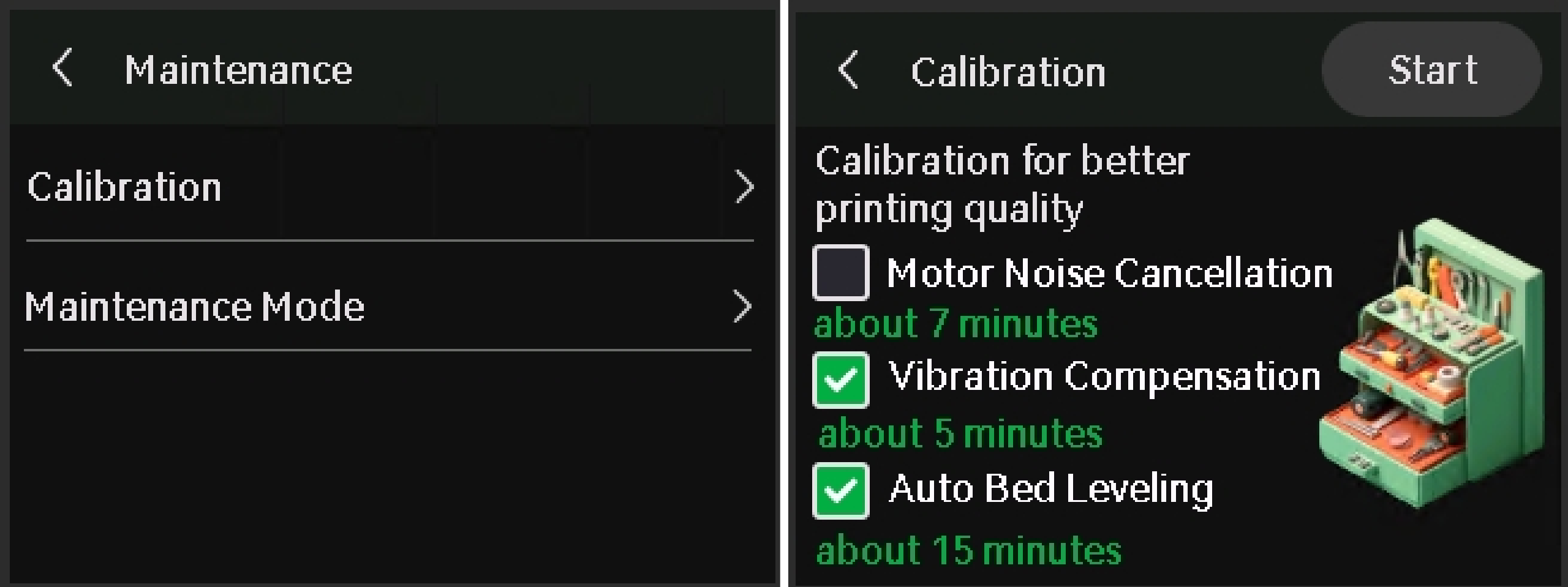
¶ Functionality Verification and Calibration Step
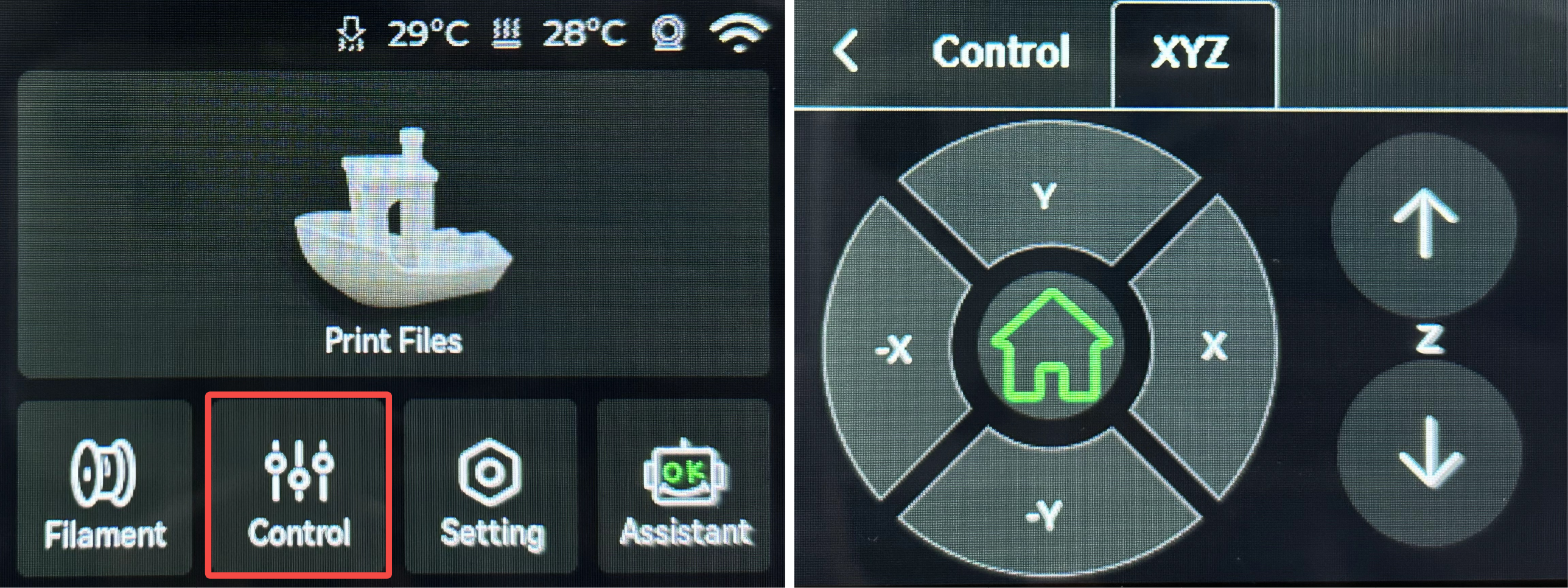
After completing all the assembly steps above, power on the printer, enter the control interface, and click the "-Y" or "Y" button on the screen to move the Y-axis and confirm whether the Y motor is functioning properly.
In the Calibration screen, select only Vibration Compensation and Auto Bed Leveling, and then tap Start.
The calibration will confirm the printer is running as expected.
¶ End Notes
We hope the detailed guide provided has been helpful and informative.
To ensure a safe and effective execution, if you have any concerns or questions about the process described in this article, we recommend submitting a technical ticket regarding your issue.
Please include a picture or video illustrating the problem, as well as any additional information related to your inquiry.