¶ Video guide
https://public-cdn.bblmw.com/wiki/A1/A1-combo-packing-guide-new-EN.mp4
¶ Operation steps
¶ Turn off the power and roll up the cable
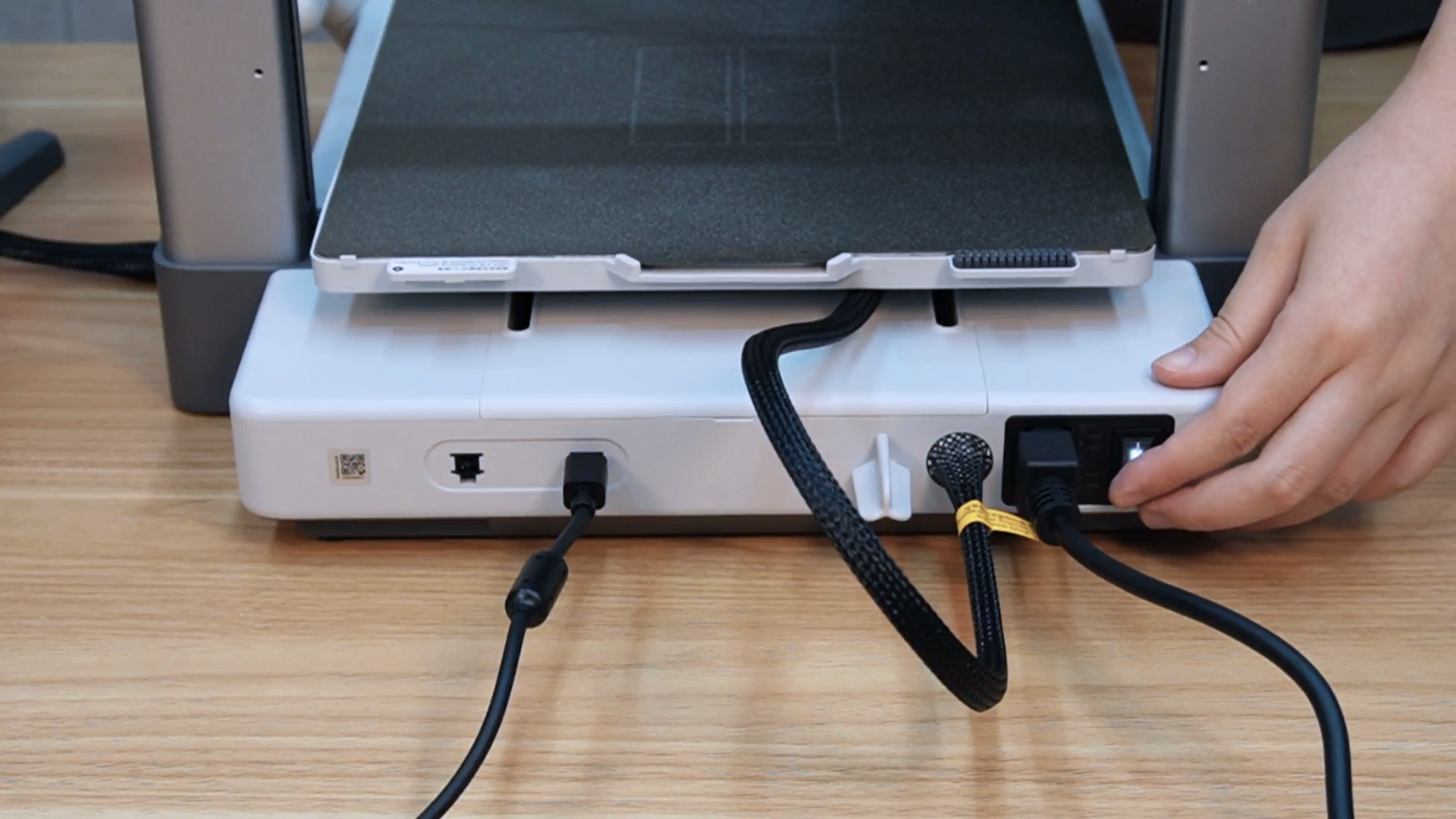
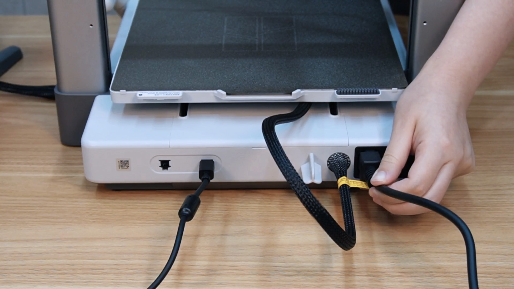
Step 1. Turn off the printer and disconnect the power cord.
 |
 |
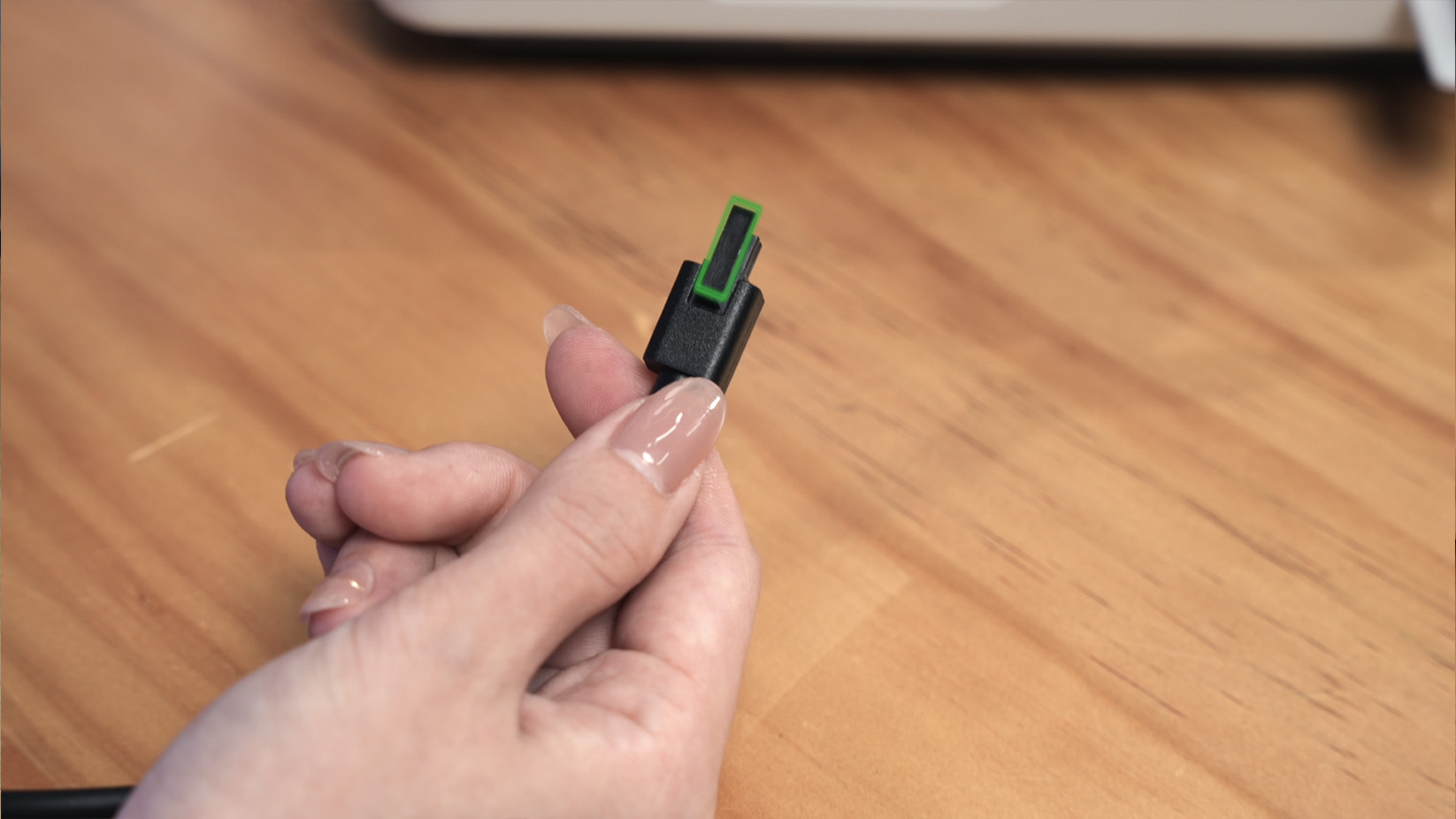
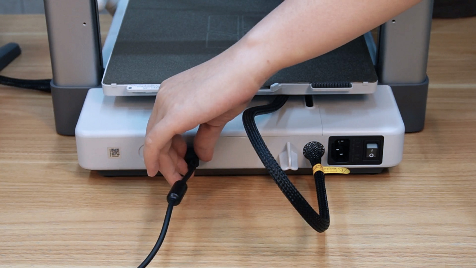
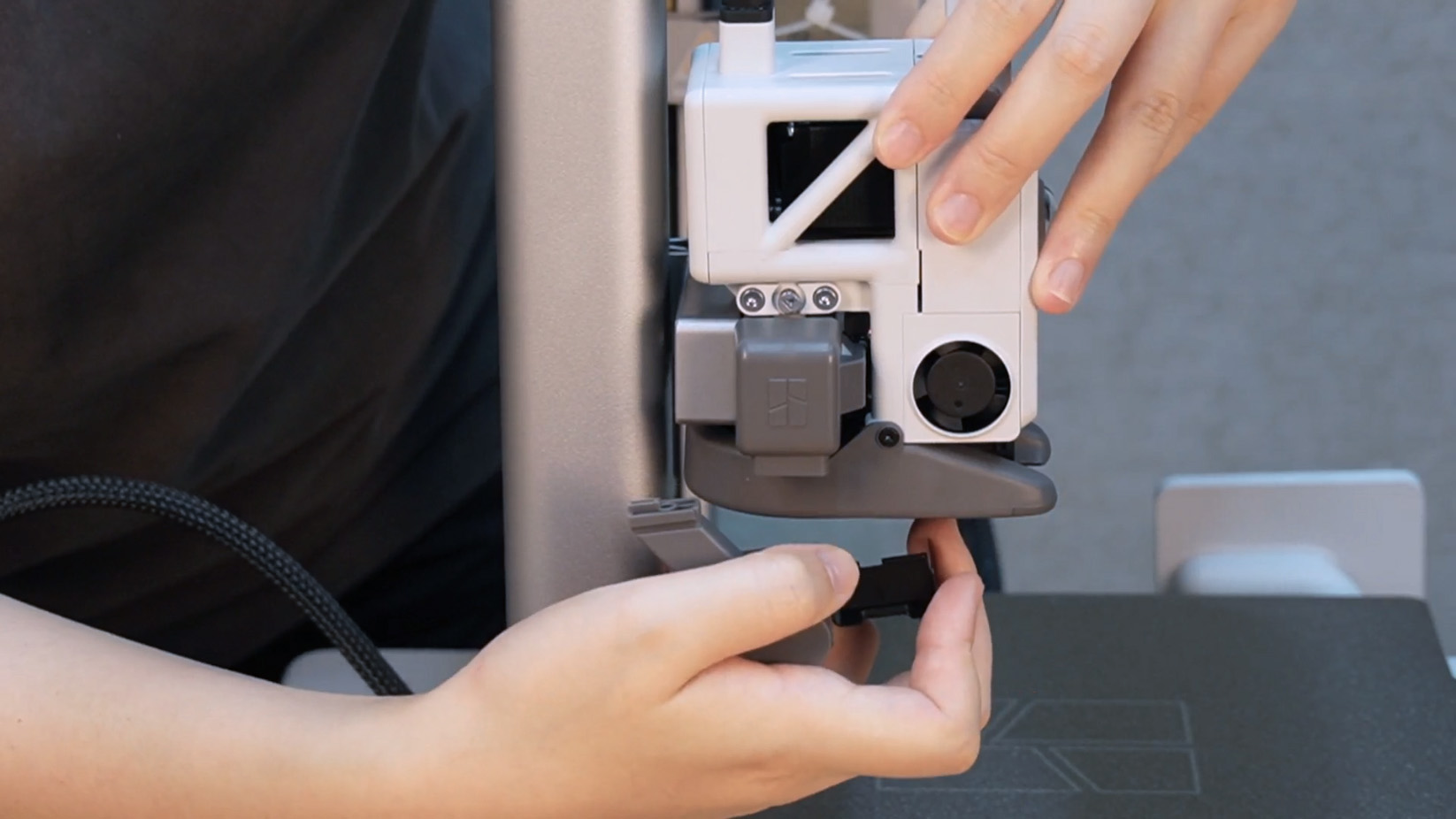
Step 2. Press the bottom of the cable connector to disconnect the 4-pin cable of AMS lite.
 |
 |
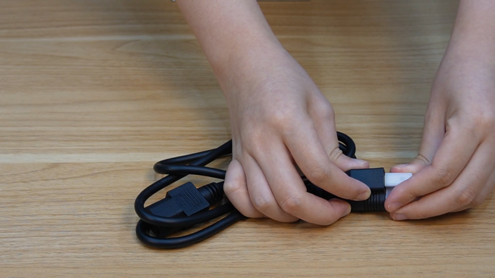
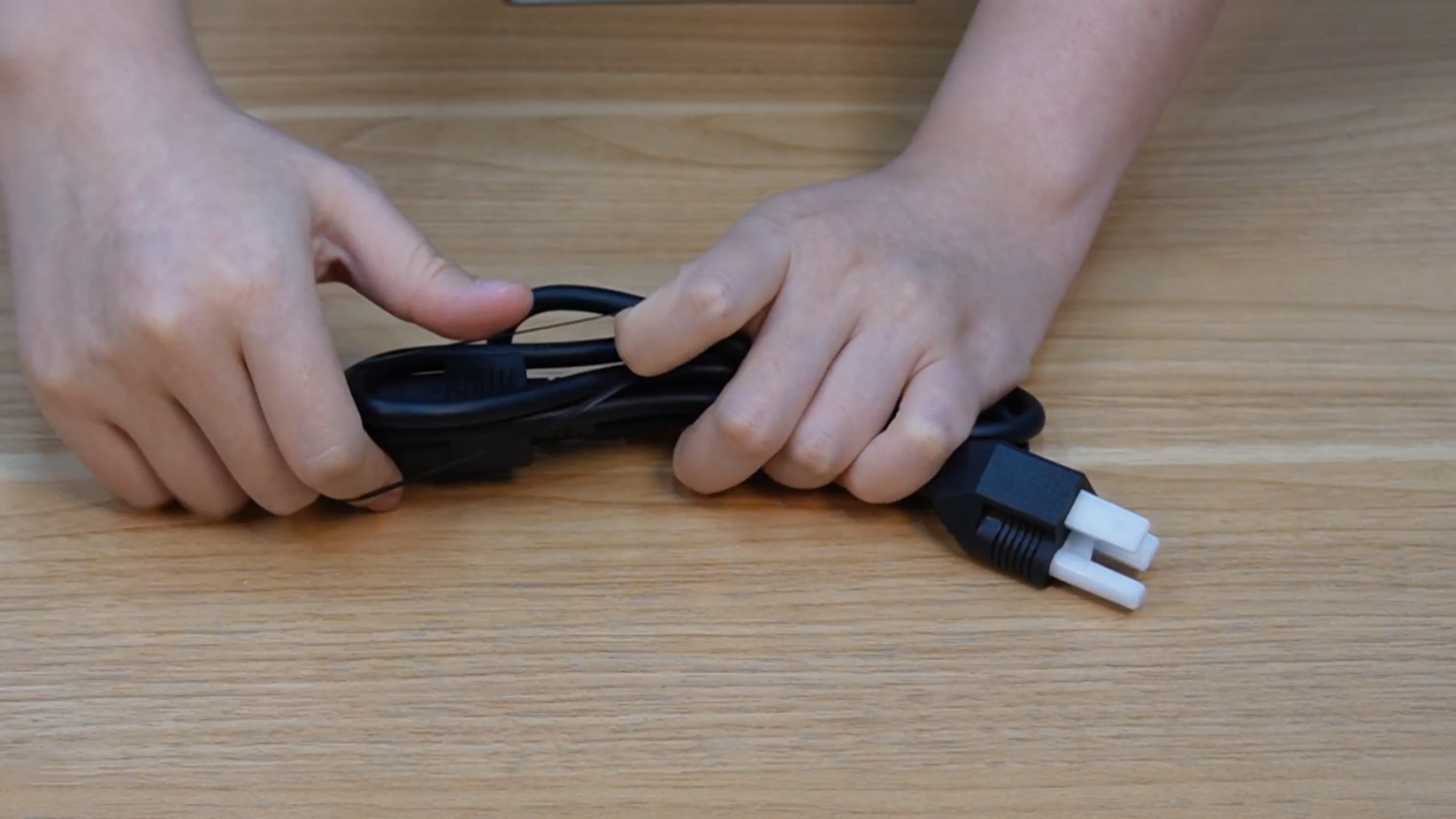
Step 3. Install the power plug cover, roll up the power cord and secure it with a rubber band.
 |
 |
¶ Remove the PTFE tube
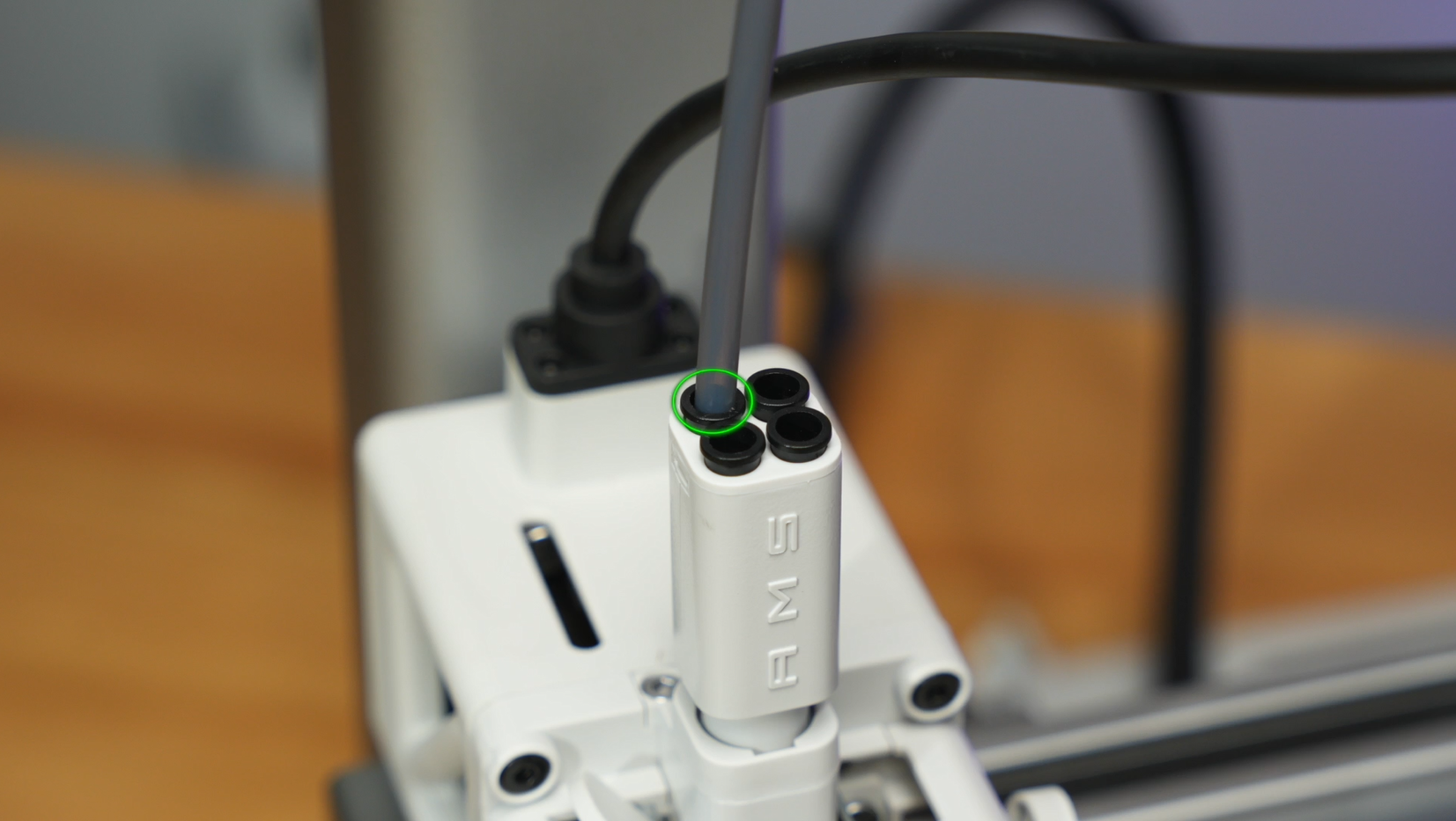
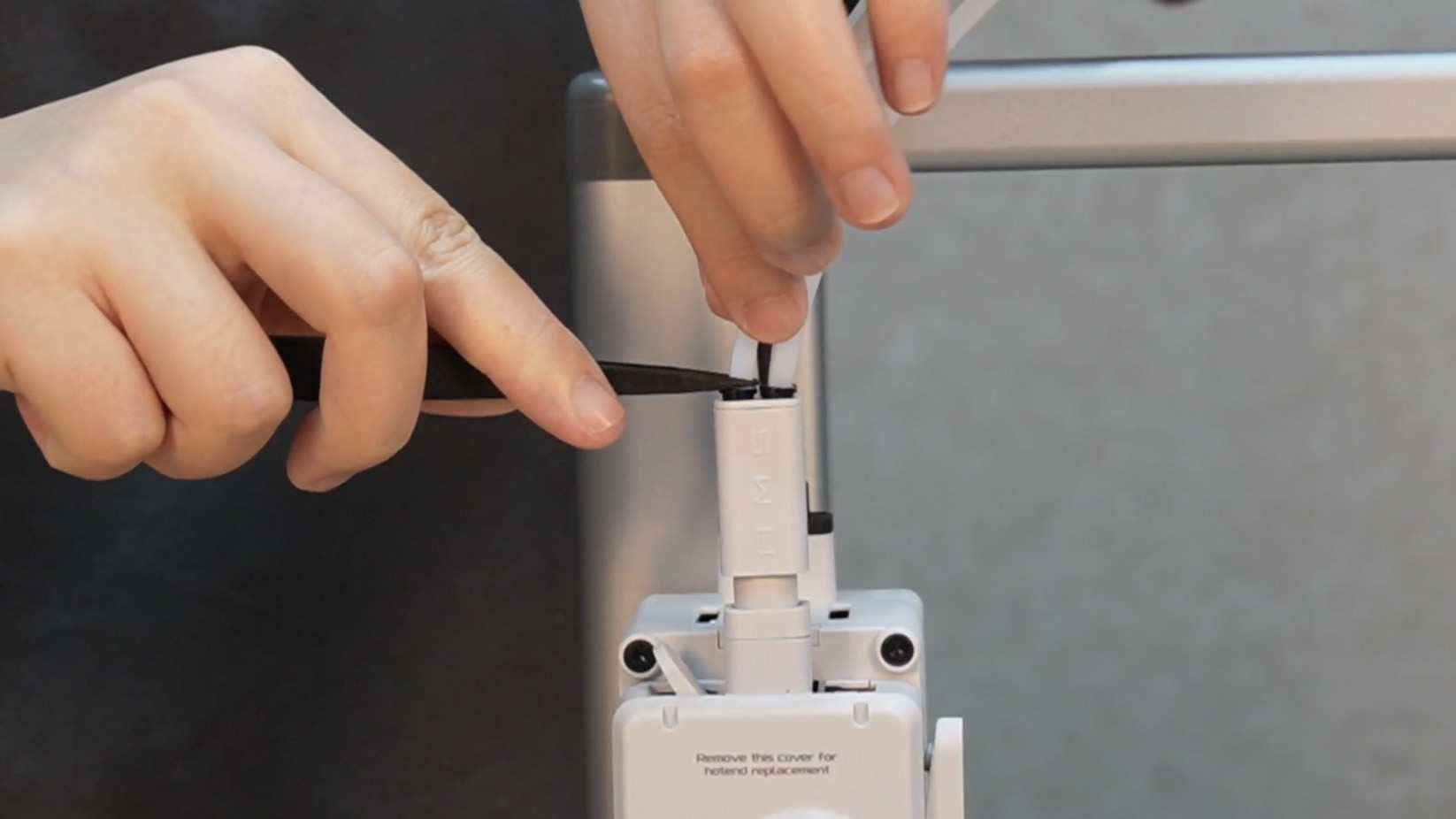
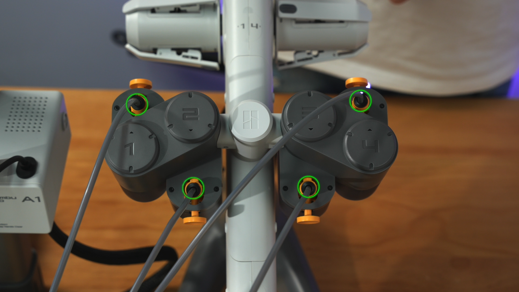
Step 1. Press the toolhead PTFE tube interface green-marked in the figure below (tweezers are recommended) and pull out the four PTFE tubes.
 |
 |
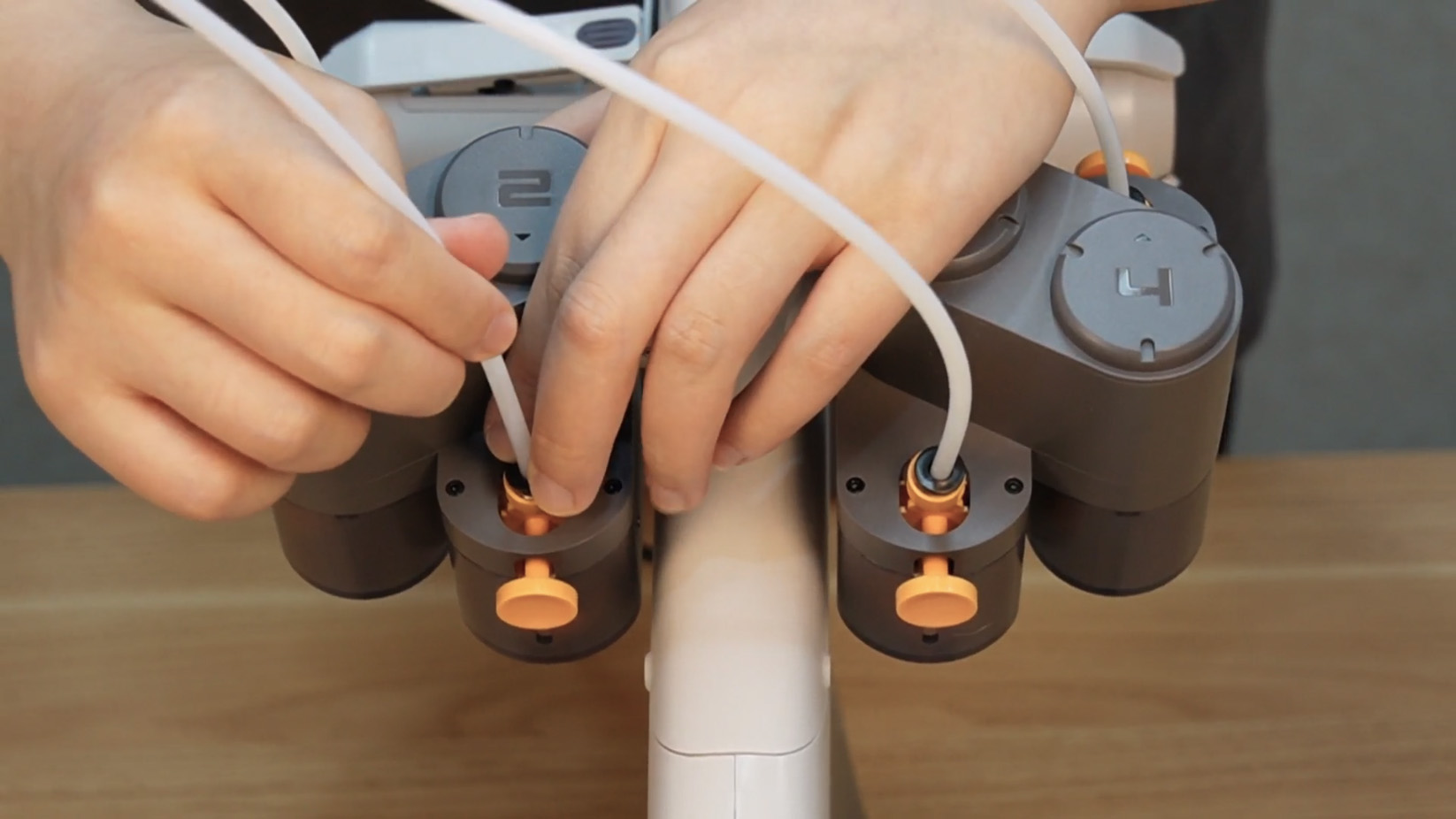
Step 2. Press the PTFE tube interface on two feeder unit to remove the PTFE tube.
 |
 |
¶ Disassemble AMS lite
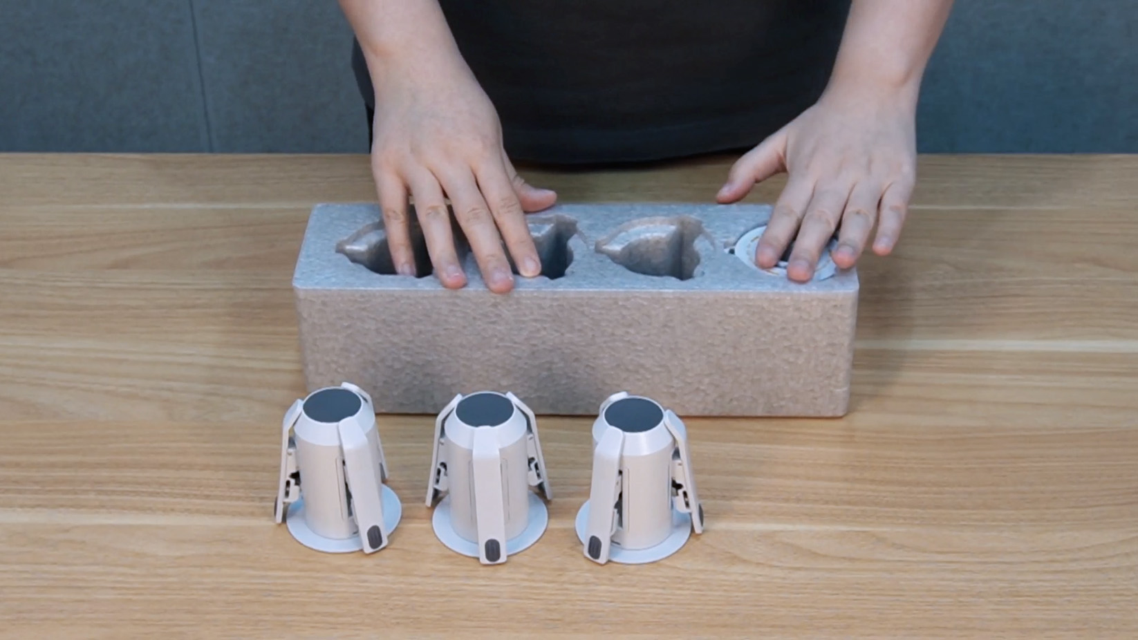
Step 1. Hold the spool claws, pull out the AMS lite rotary spool holders, and put them back into the foam box.
 |
 |
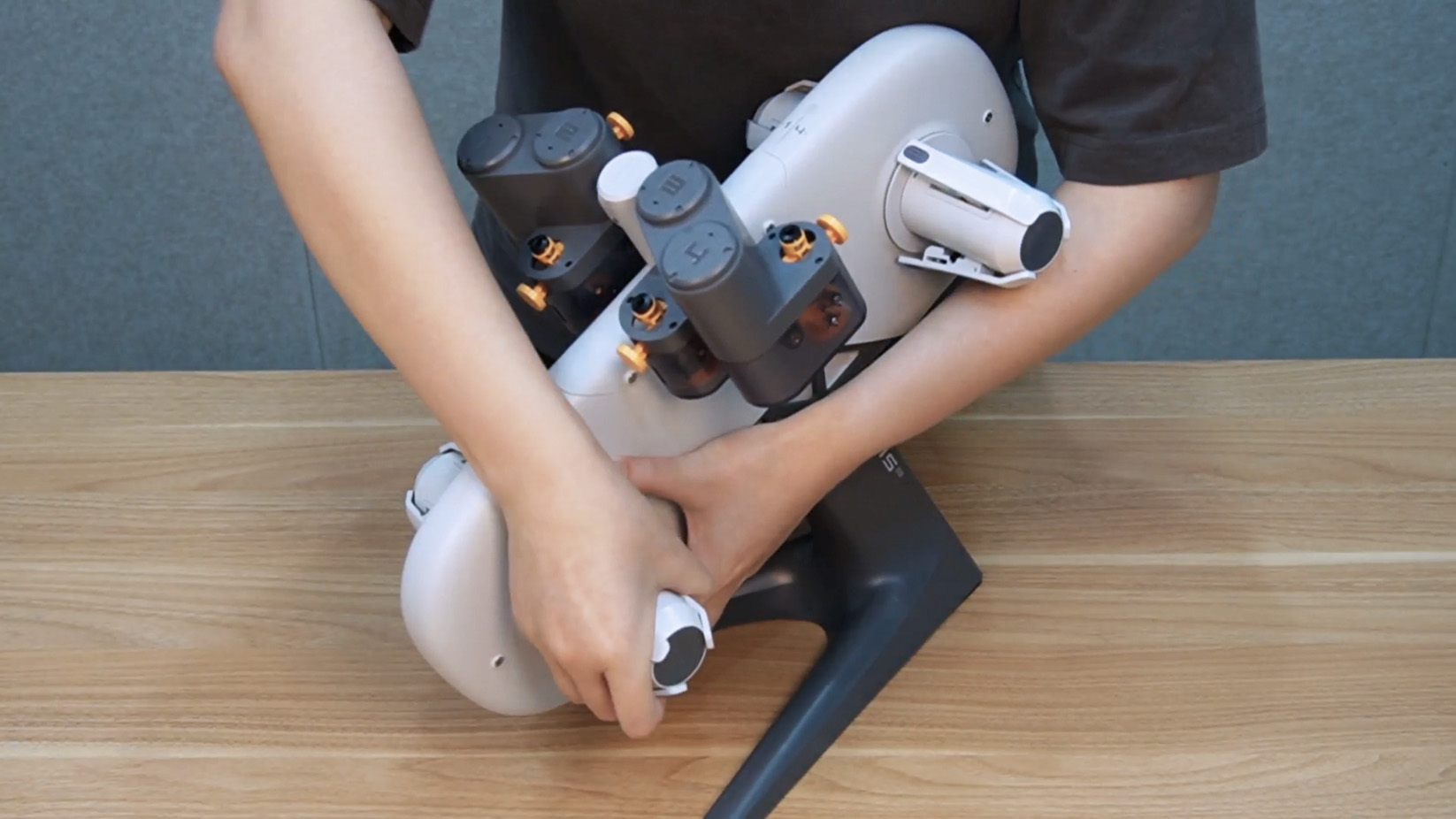
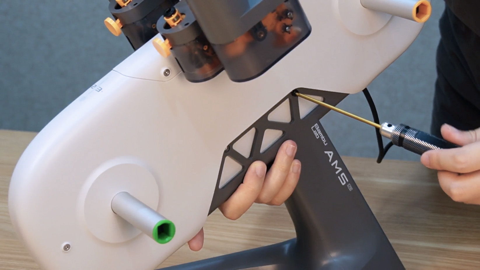
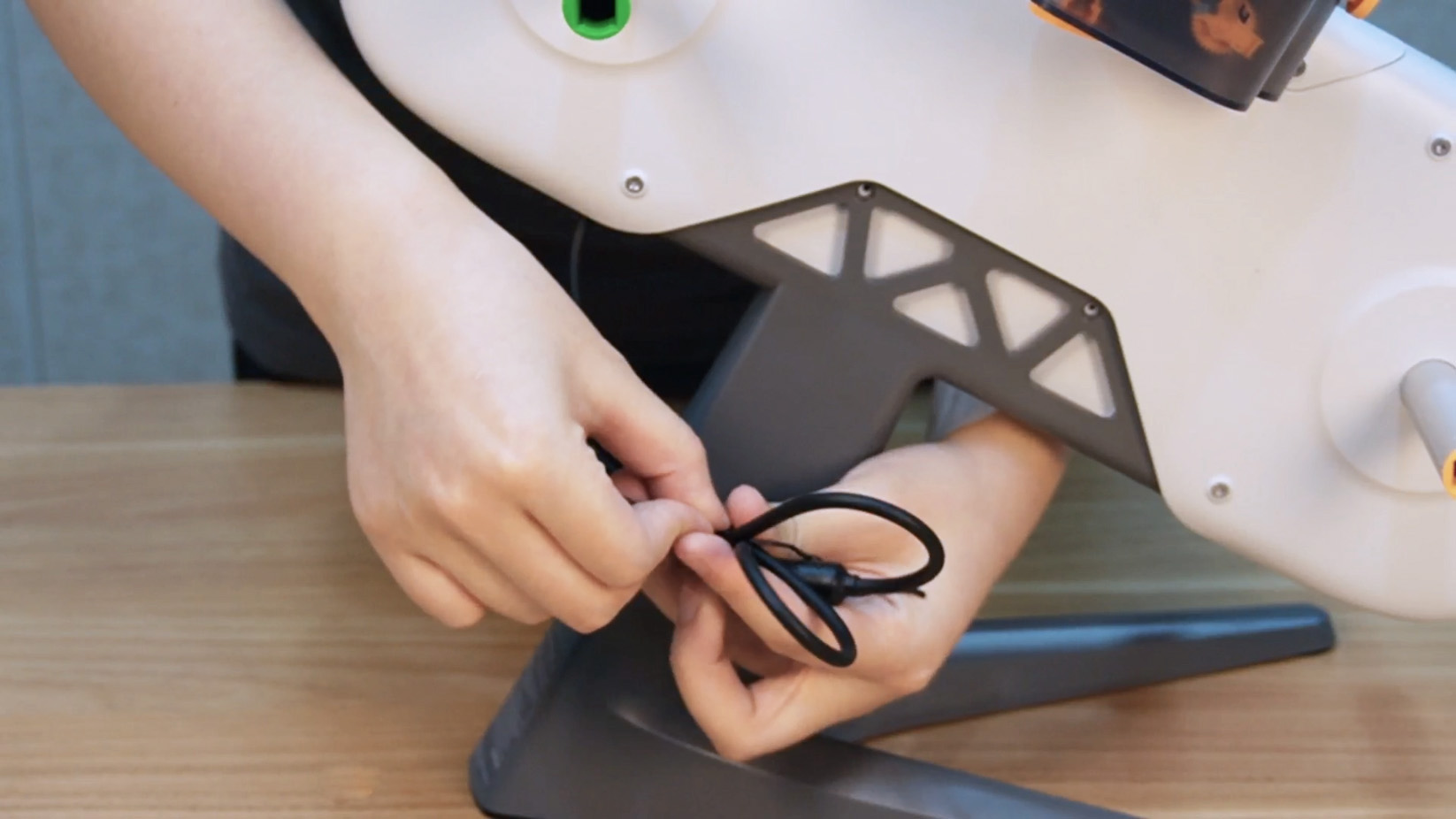
Step 2. Remove the four screws connecting the AMS lite body and the stand, and tie up the cable.
 |
 |
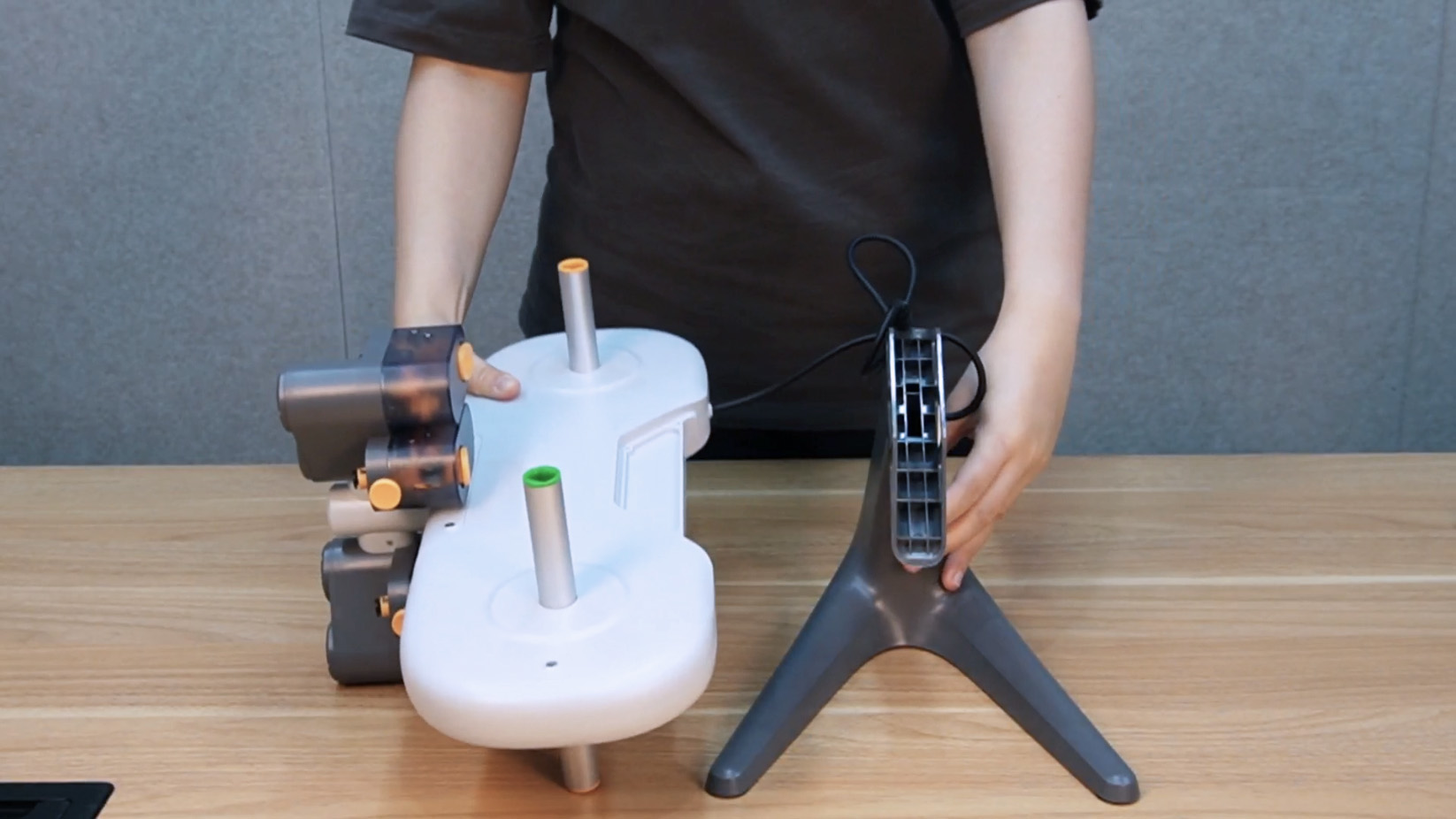
Step 3. Remove the AMS lite body and put it back into the foam box.
 |
 |
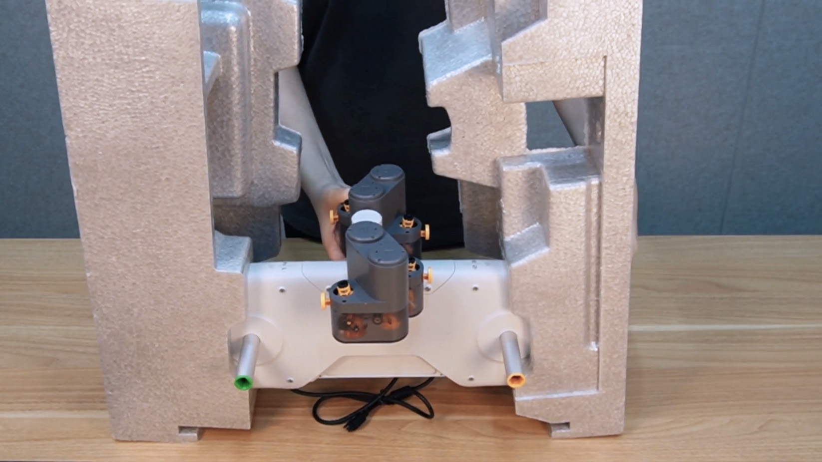 |
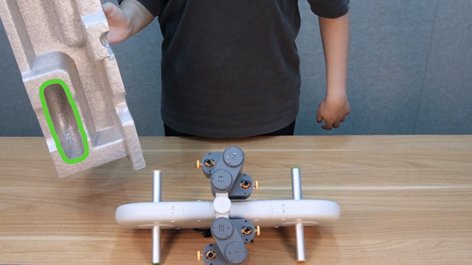
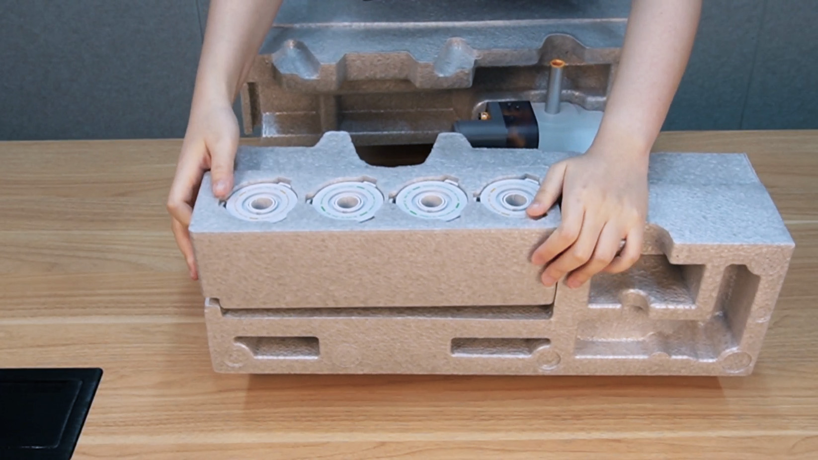
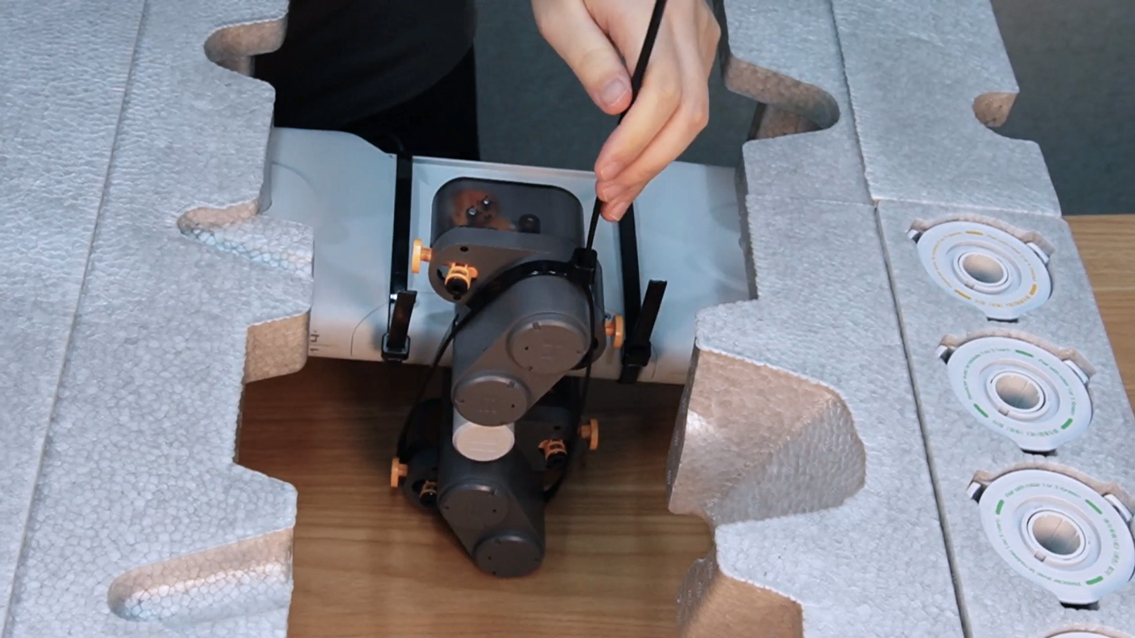
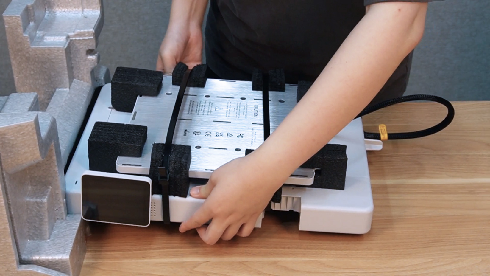
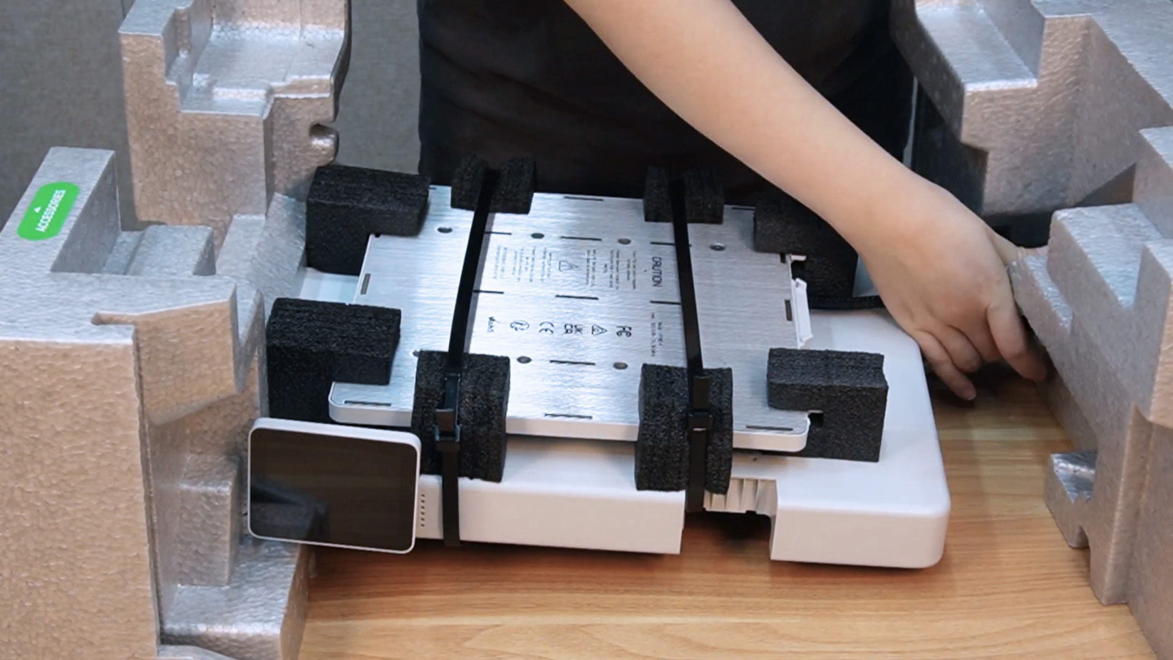
Step 4. Place the foam box with the rotary spool holders into the packaging of the AMS lite body, and secure the AMS lite body with cable ties.
 |
|
 |
¶ Fix the Z-axis, toolhead, and X-axis
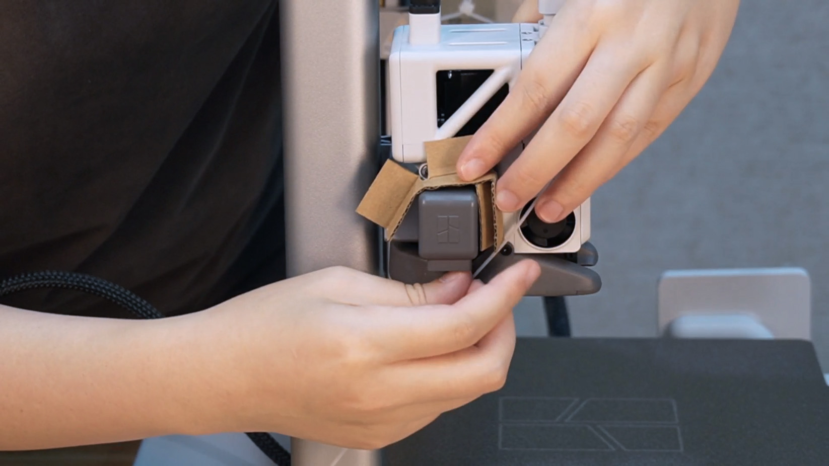
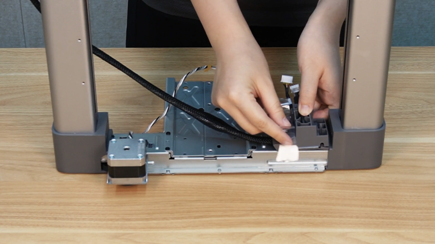
Step 1. Move the toolhead to the far left, remove the purge wiper, place cardboard against the toolhead, and secure with a cable tie.
 |
 |
 |
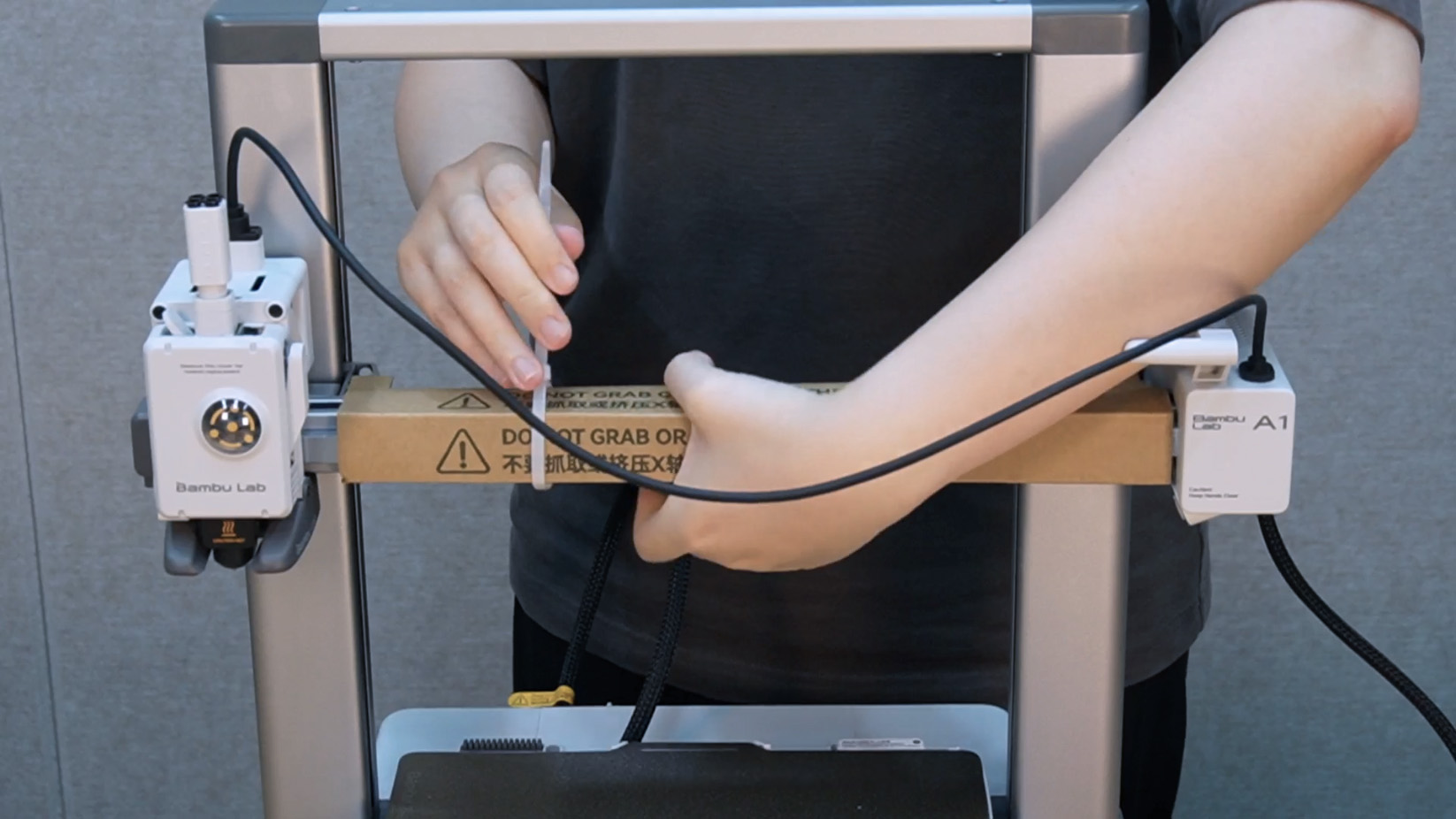
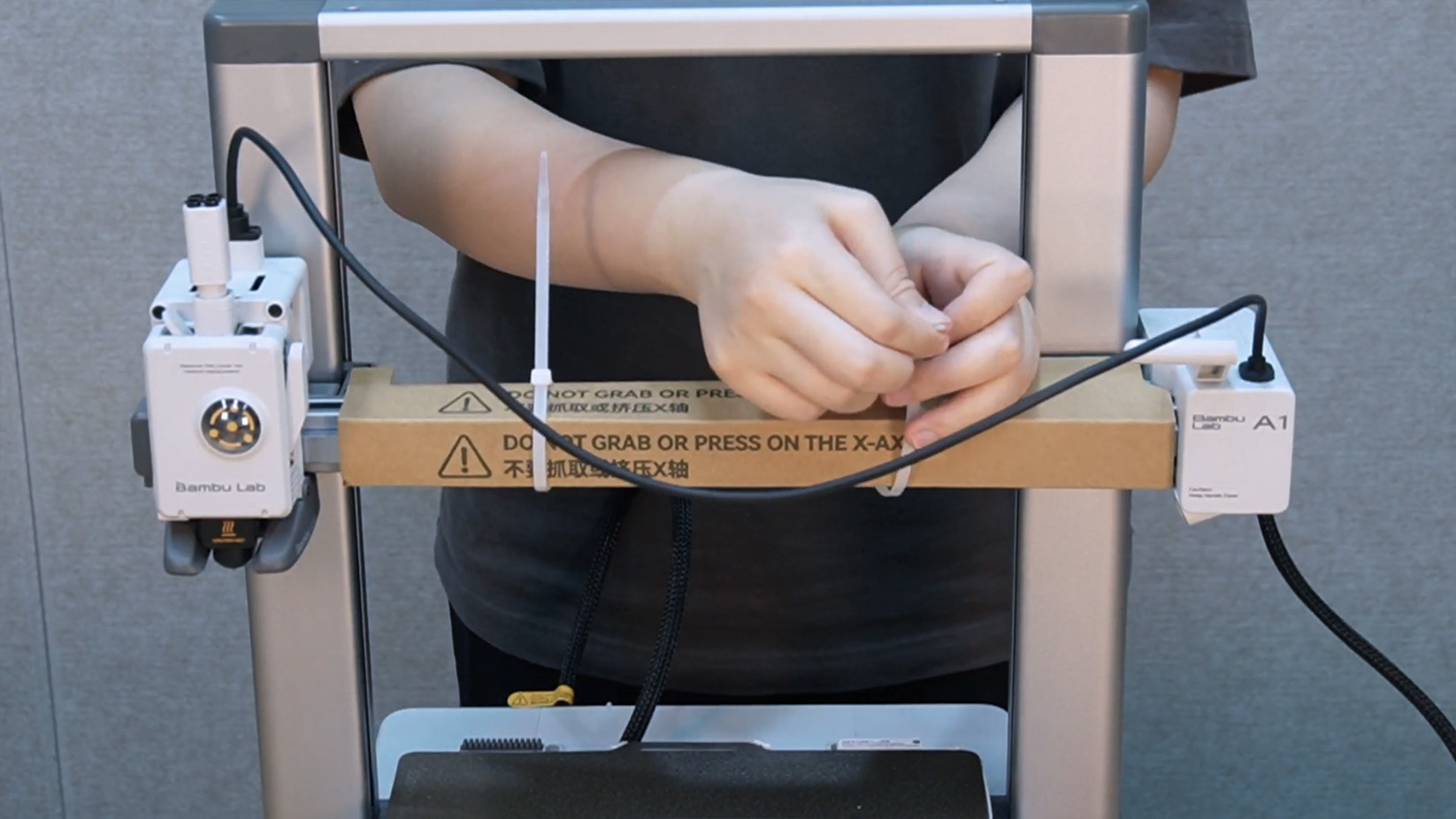
Step 2. Wrap the X-axis with cardboard and secure the cable and cardboard with cable ties.
 |
 |
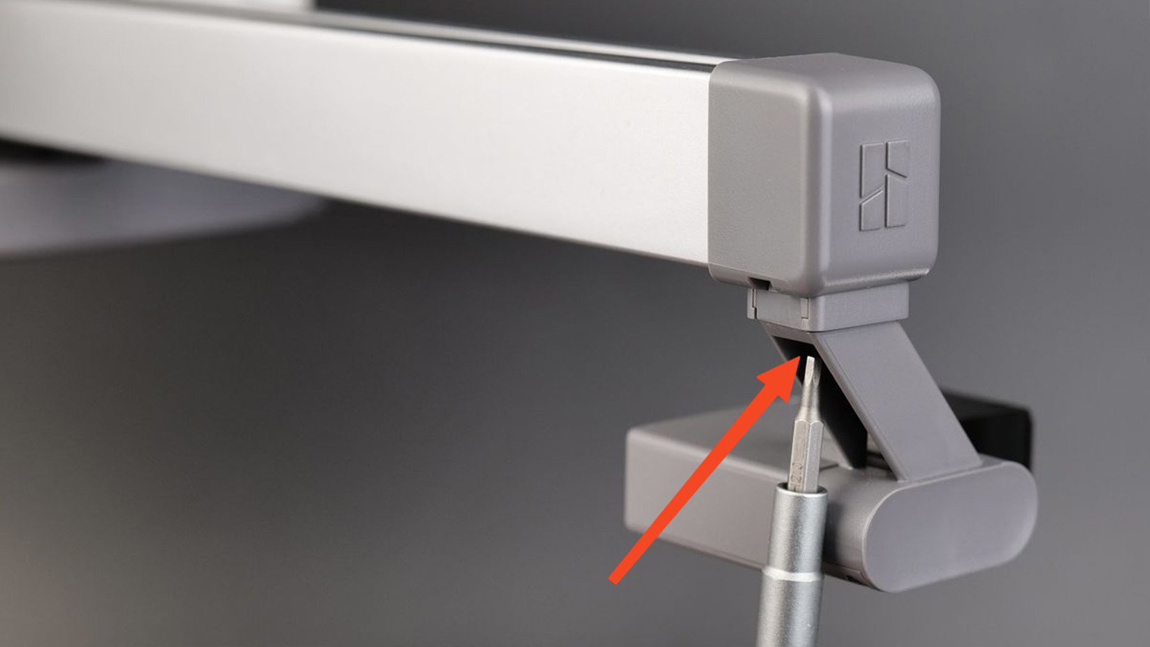
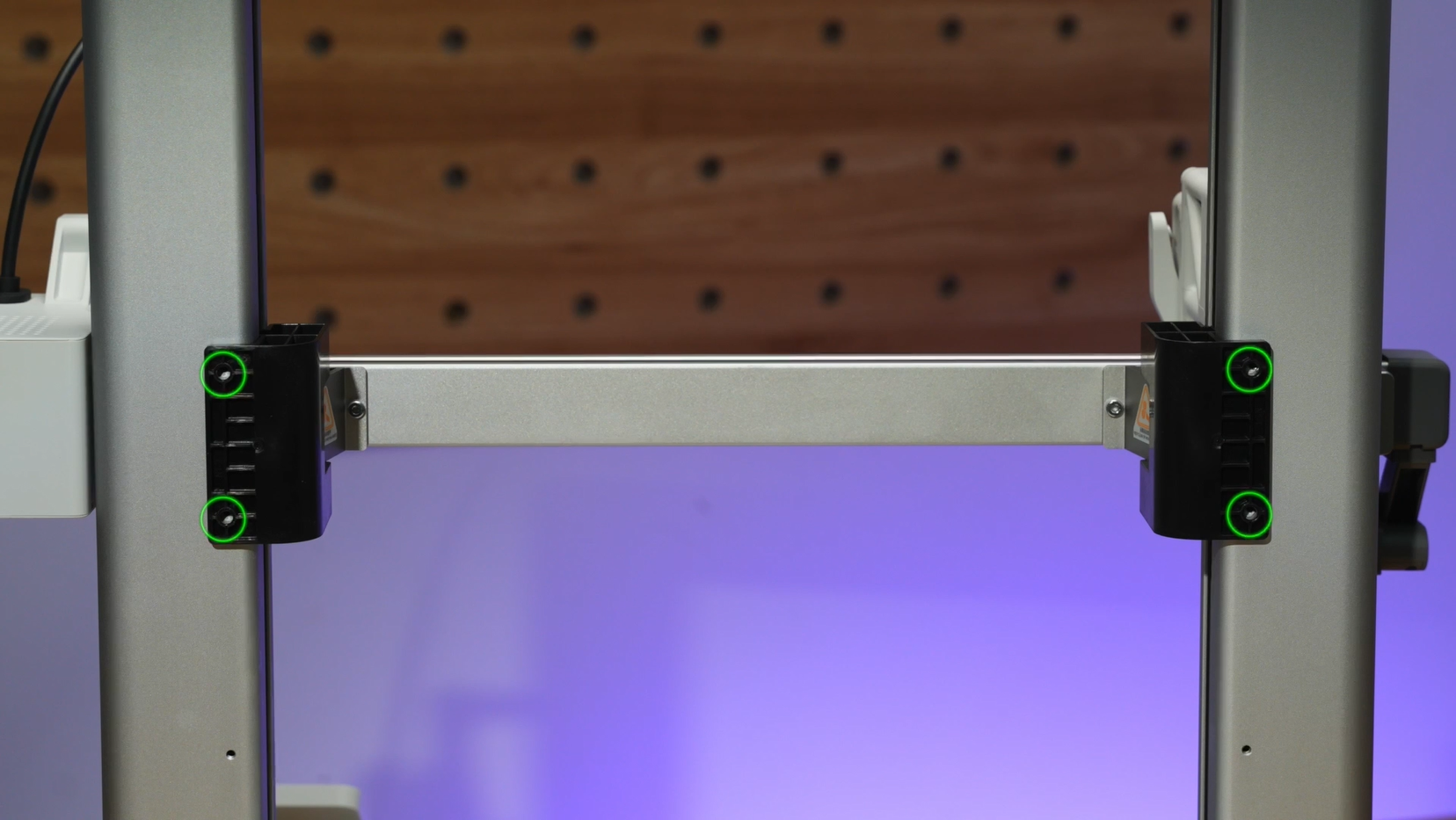
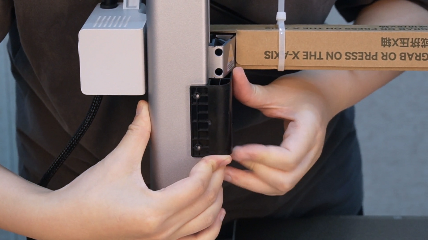
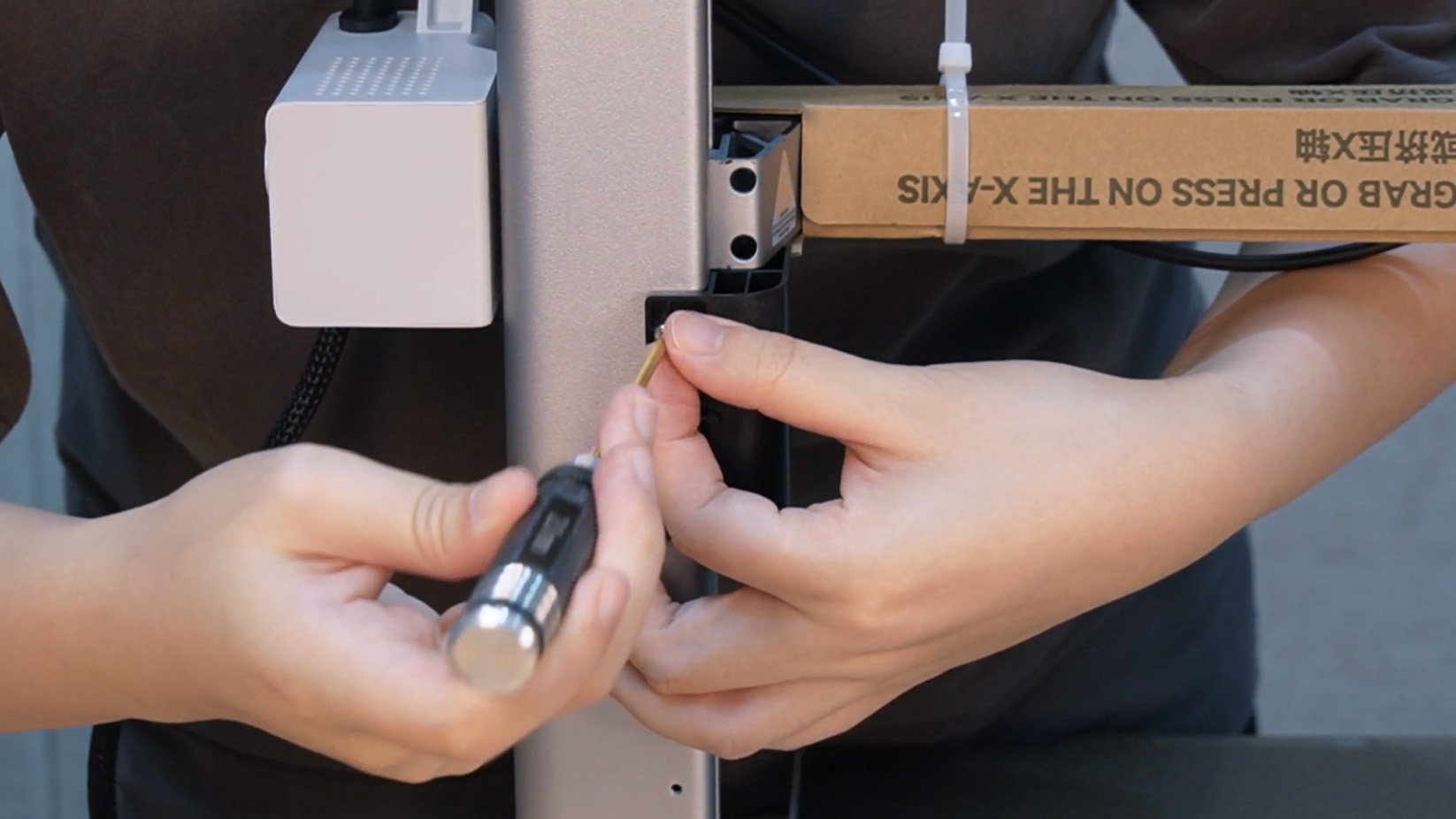
Step 3. Install the Z-axis limiter, align the Z-axis limiter screw positions, and tighten the four screws.
 |
 |
 |
¶ Remove the cable box and printer frame
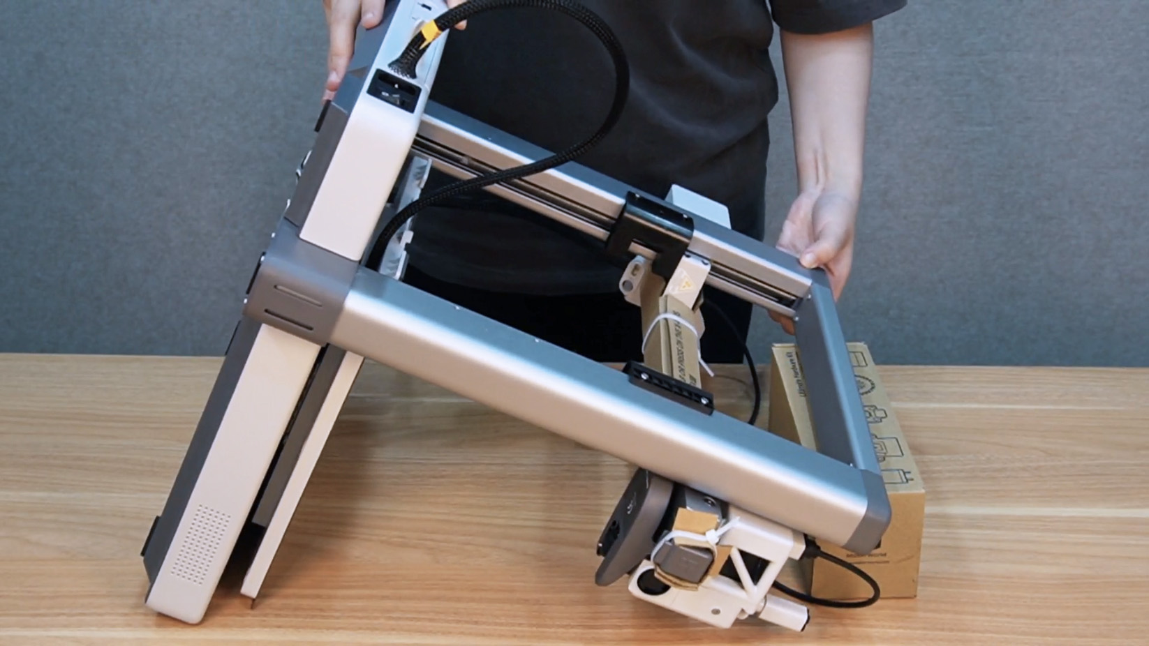
Step 1. Lay the printer flat.
NOTE: The printer frame needs to be elevated to avoid damaging the toolhead.
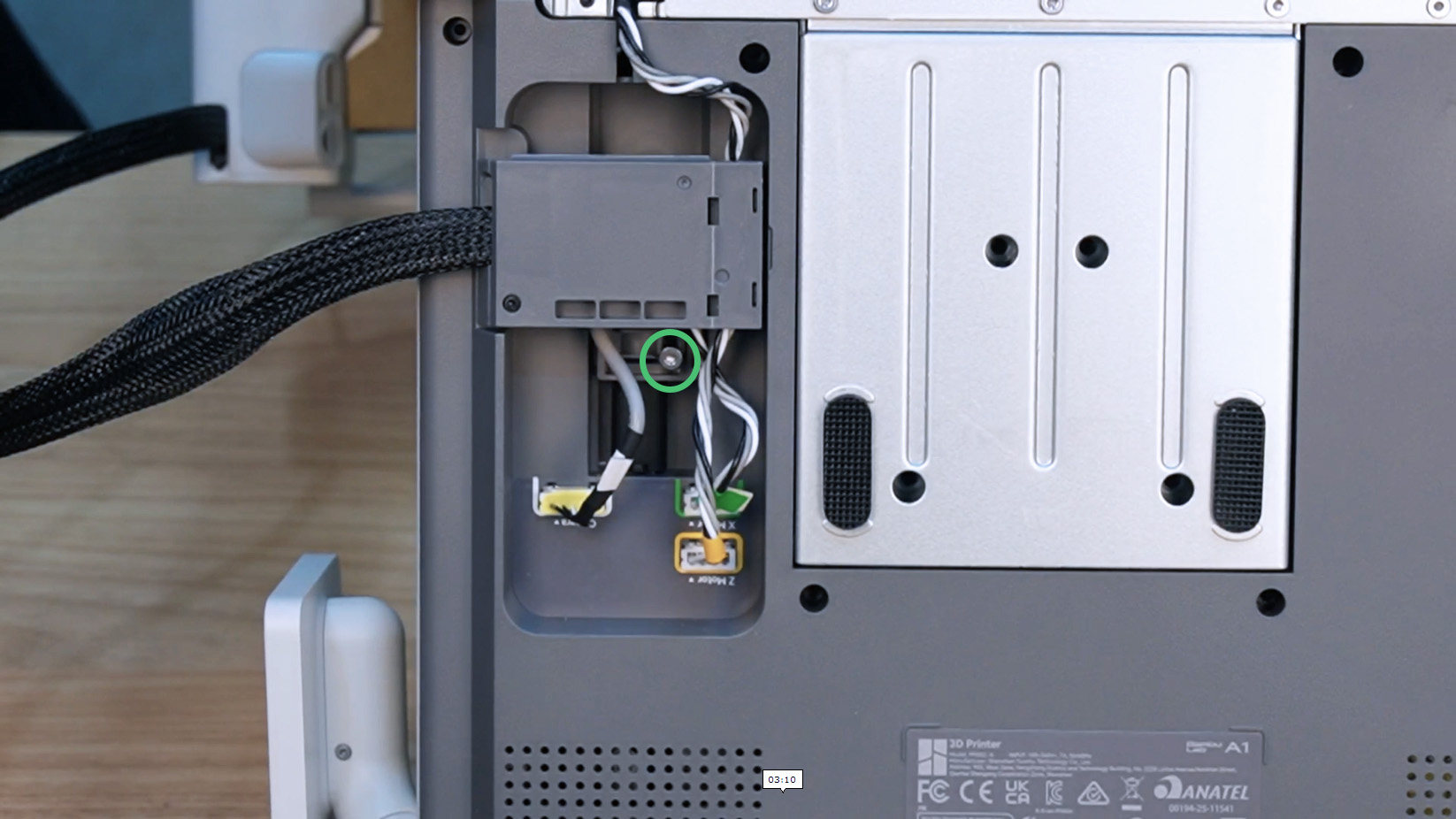
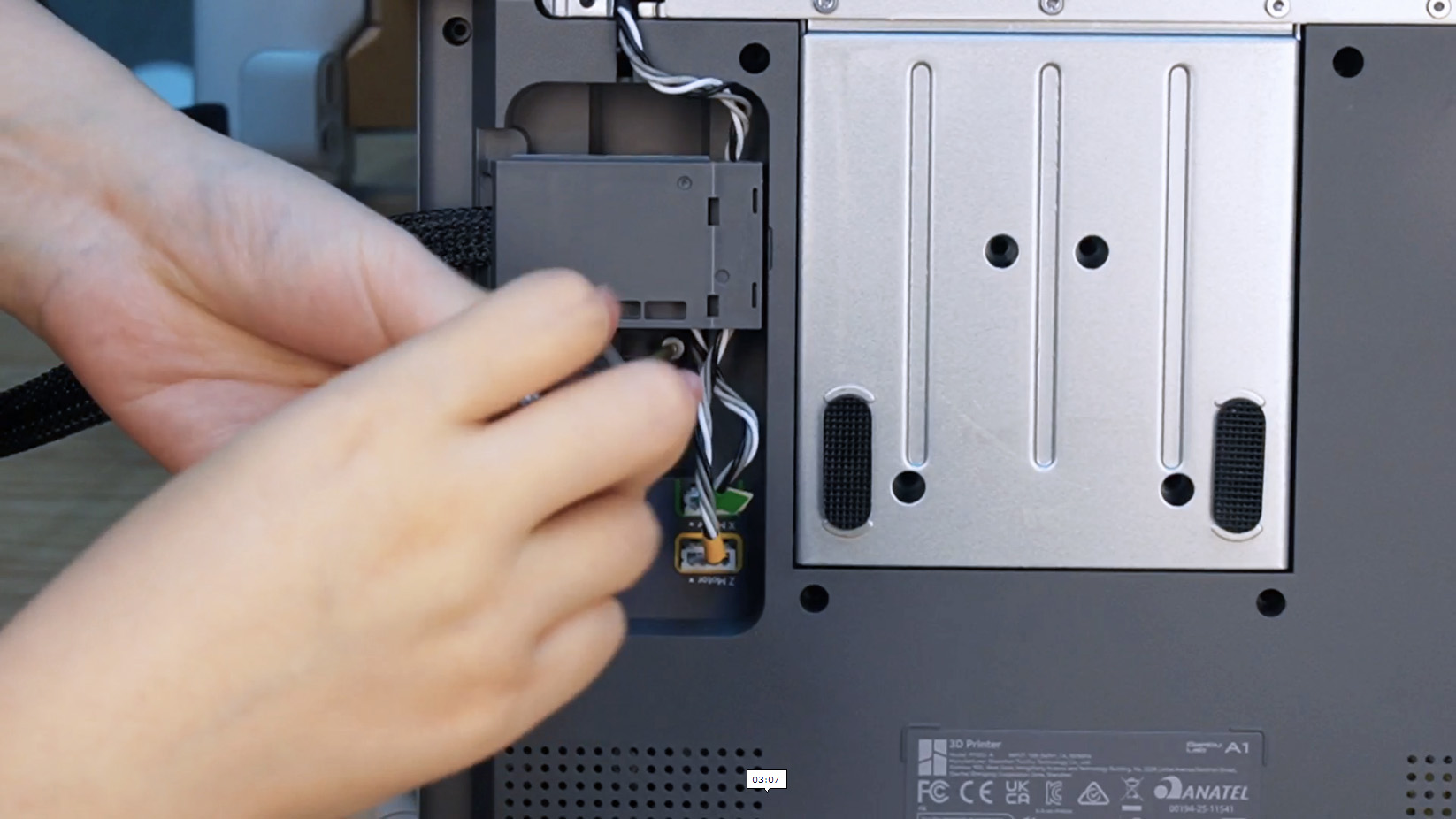
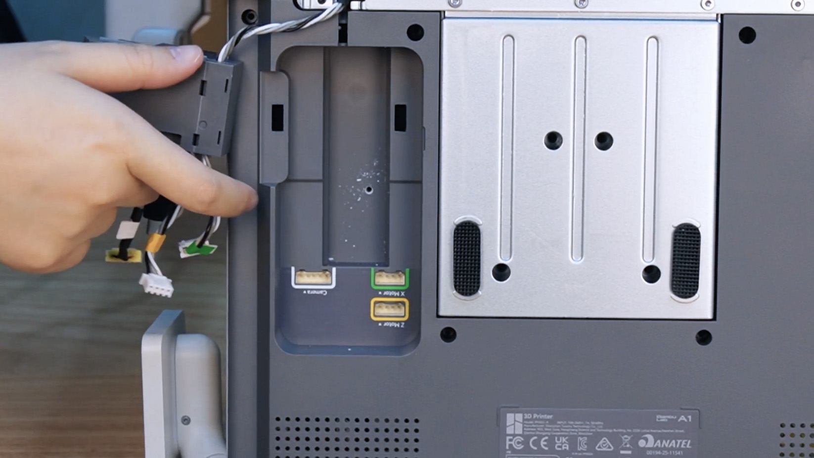
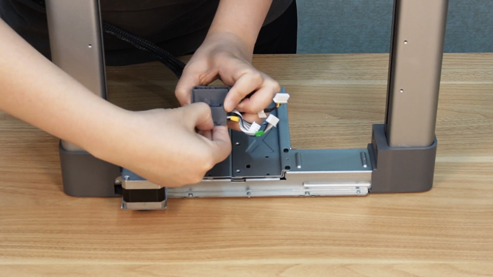
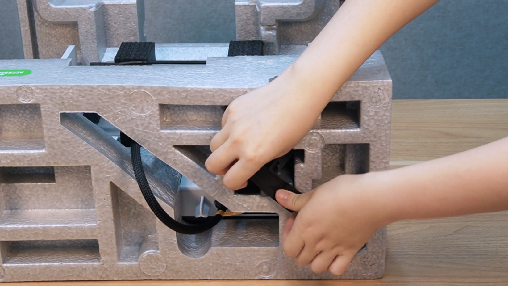
Step 2. Loosen the pre-installed screws of the cable box at the location shown and unplug the 3 connectors.
 |
 |
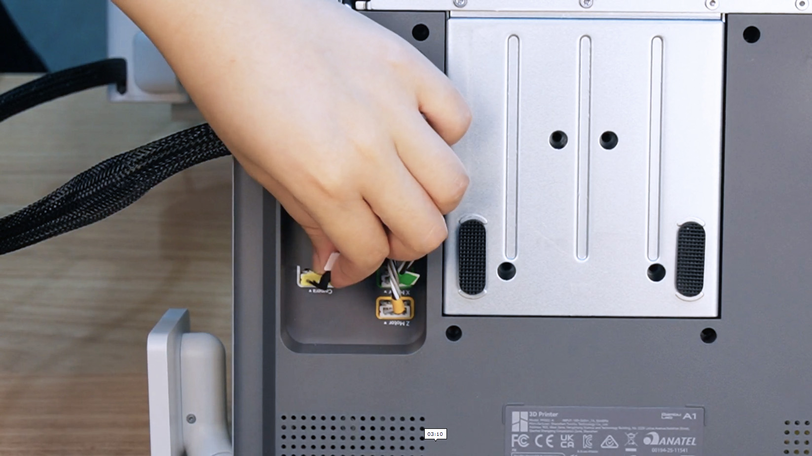 |
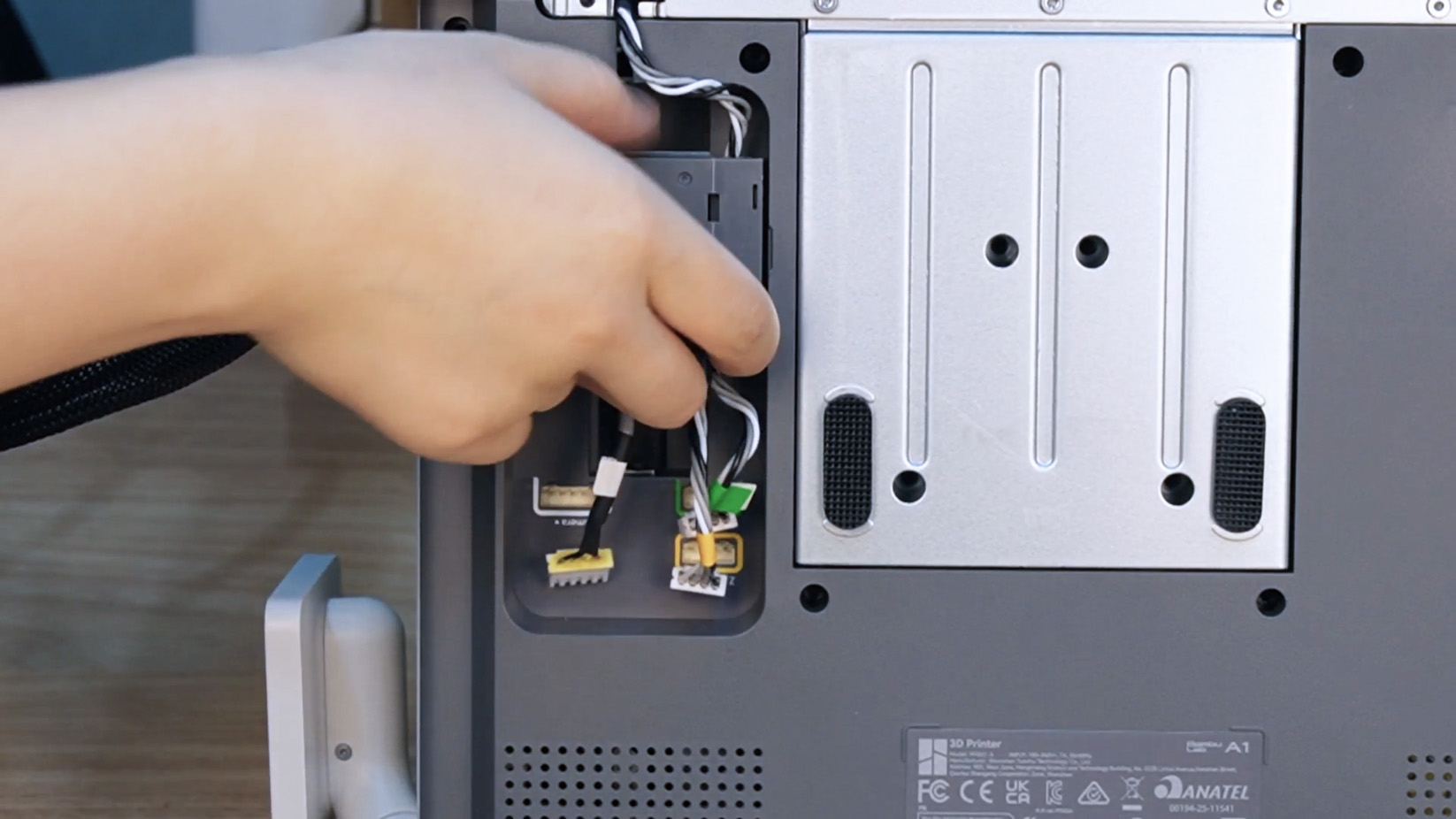
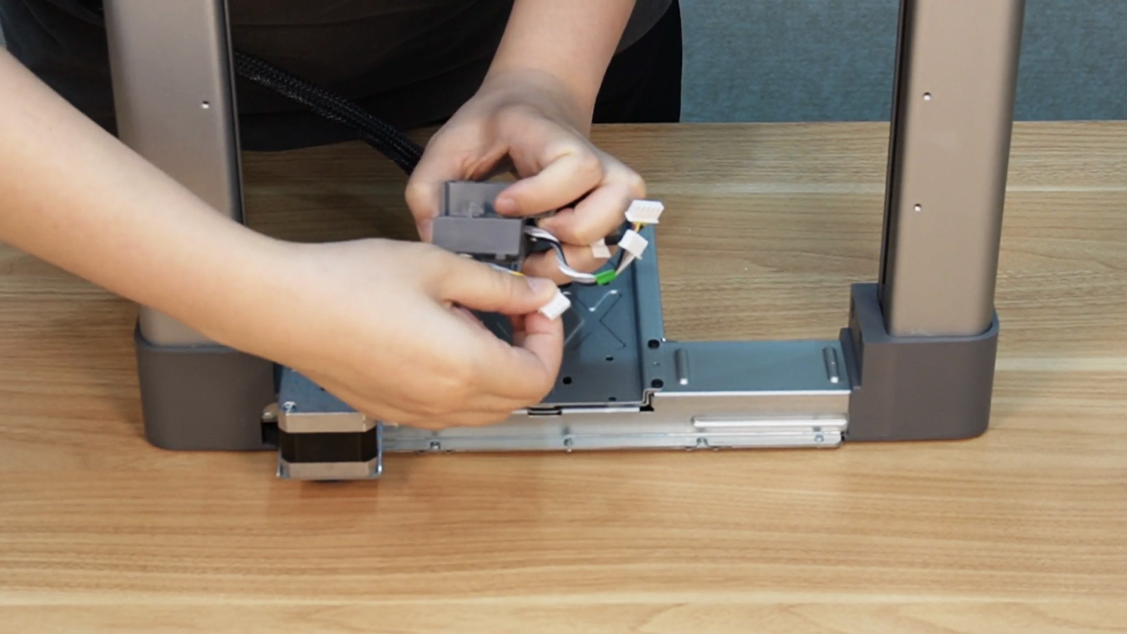
Step 3. Push the cable box downward, unplug Type-C cables from connectors, and remove the cable box.
 |
 |
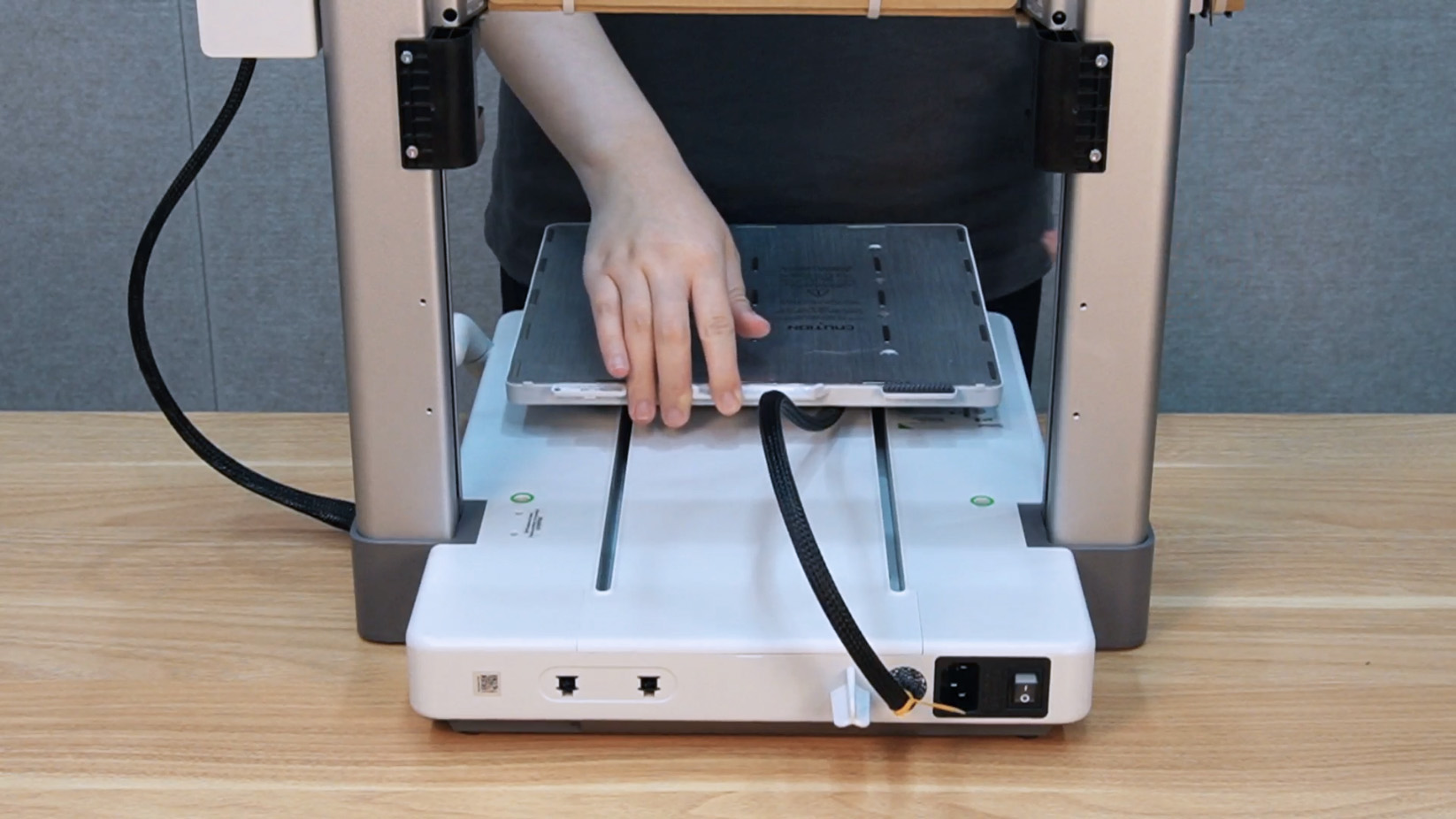
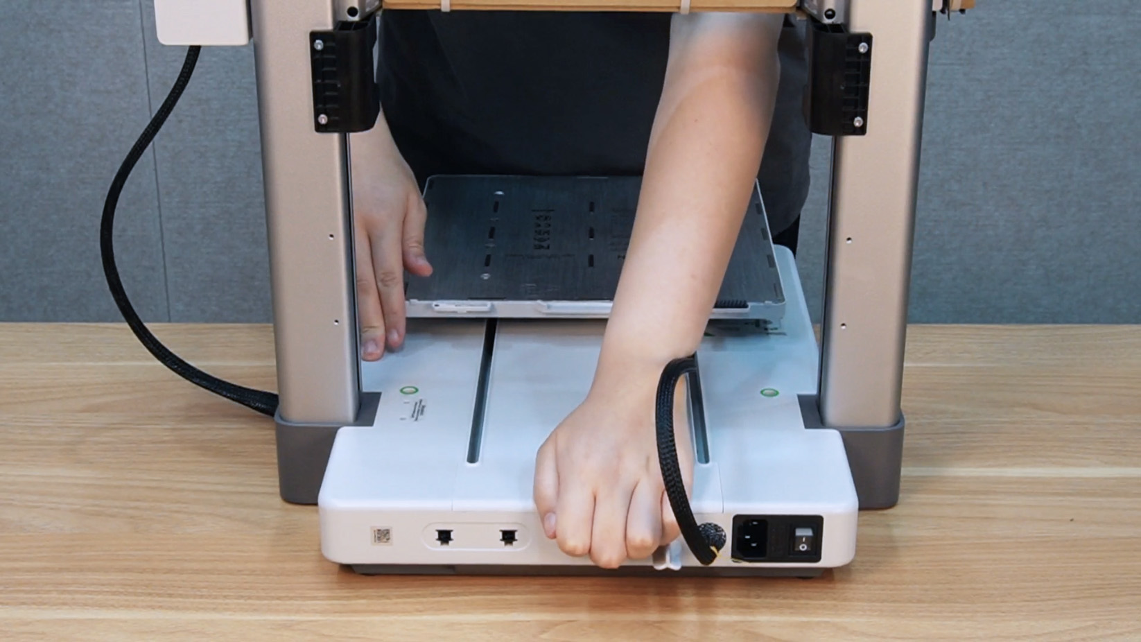
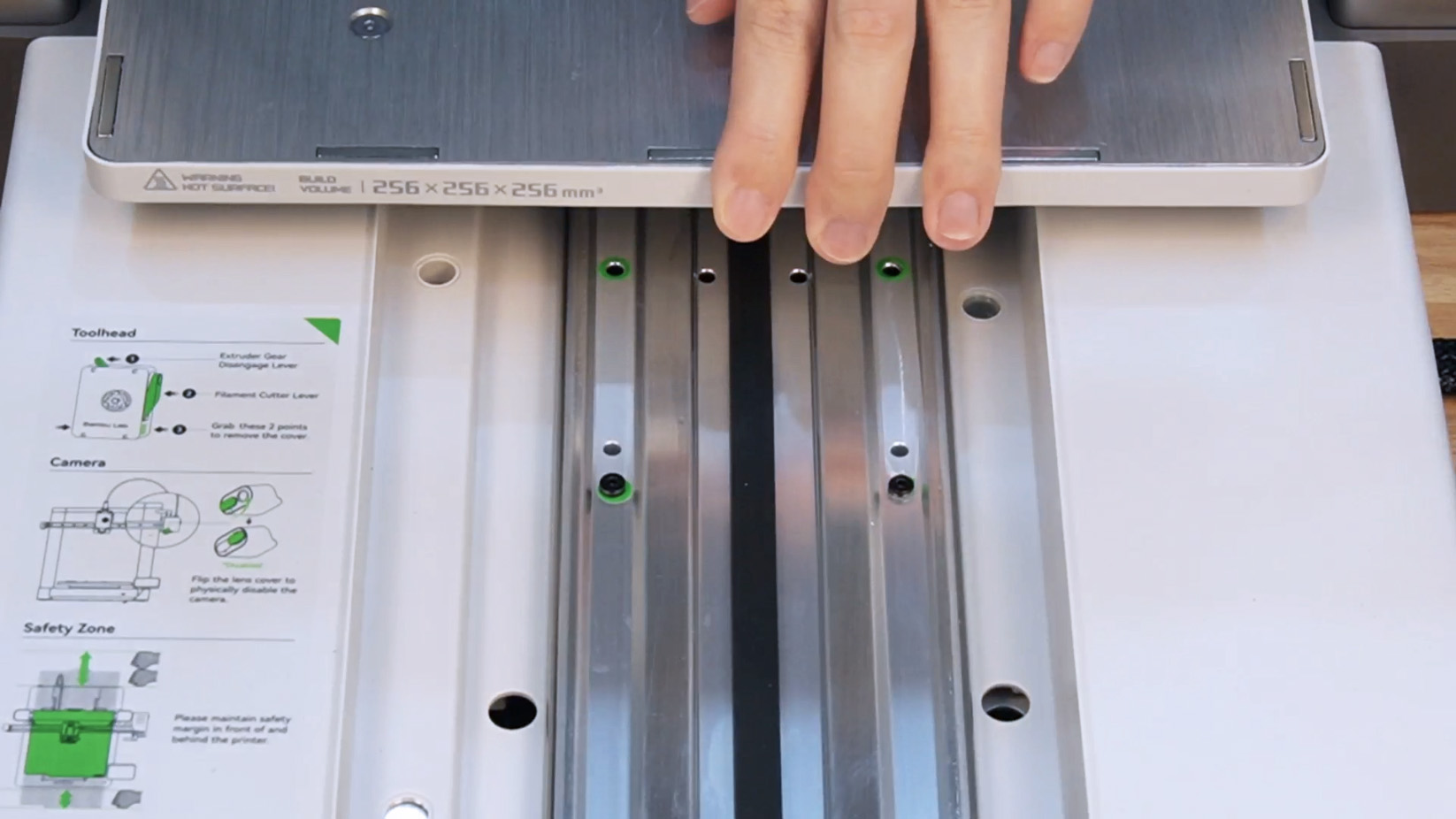
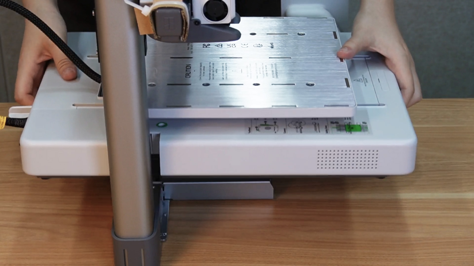
Step 4. Lay the printer flat, remove the build plate, push the heatbed to the front of the printer, and remove the Y-axis linear rail cover under the heatbed.
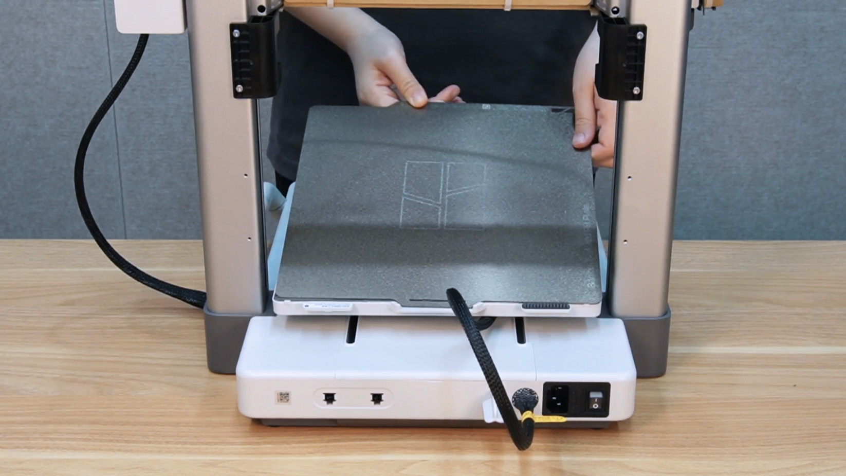 |
 |
 |
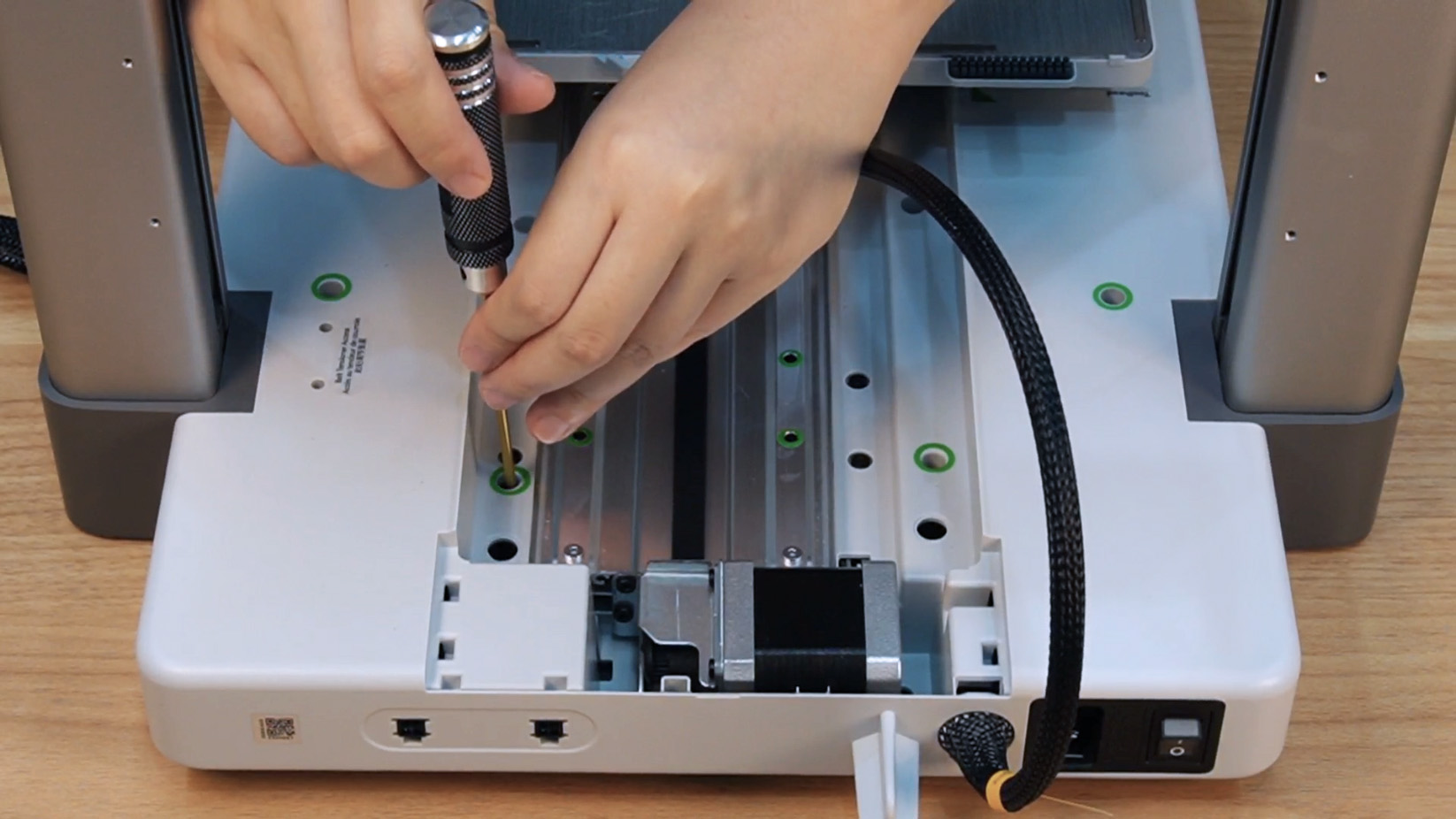
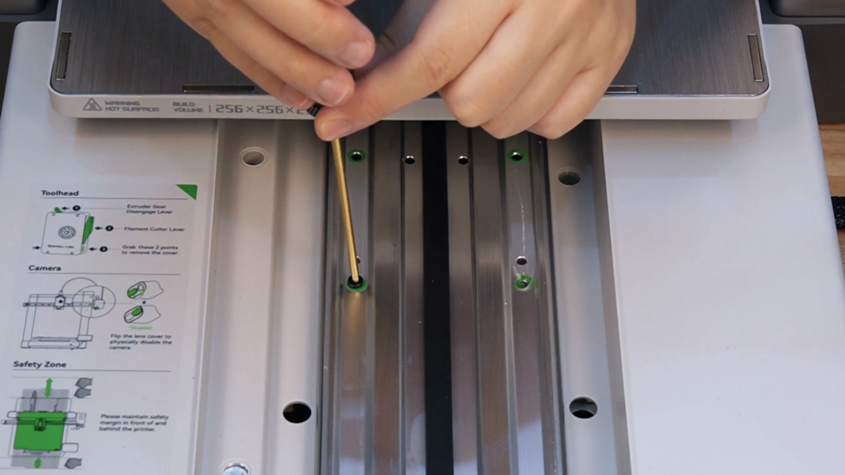
Step 5. Remove all the green-marked screws, push the heatbed to the back of the printer, and remove the remaining 4 green-marked screws.
 |
 |
 |
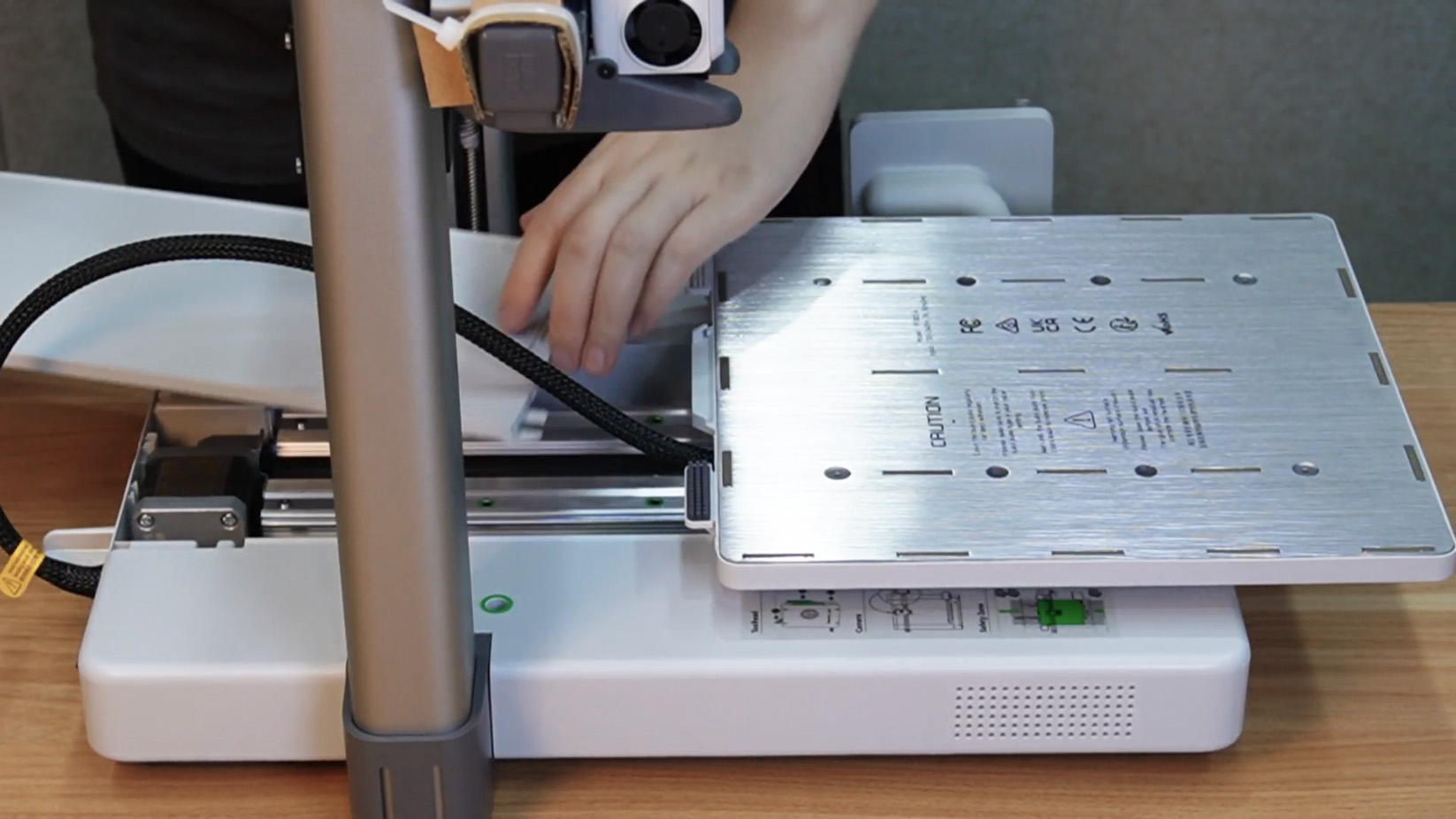
Step 6. Reinstall the Y-axis linear rail cover, lift the printer base and tilt it slightly, then separate the base from the printer frame and remove it.
 |
 |
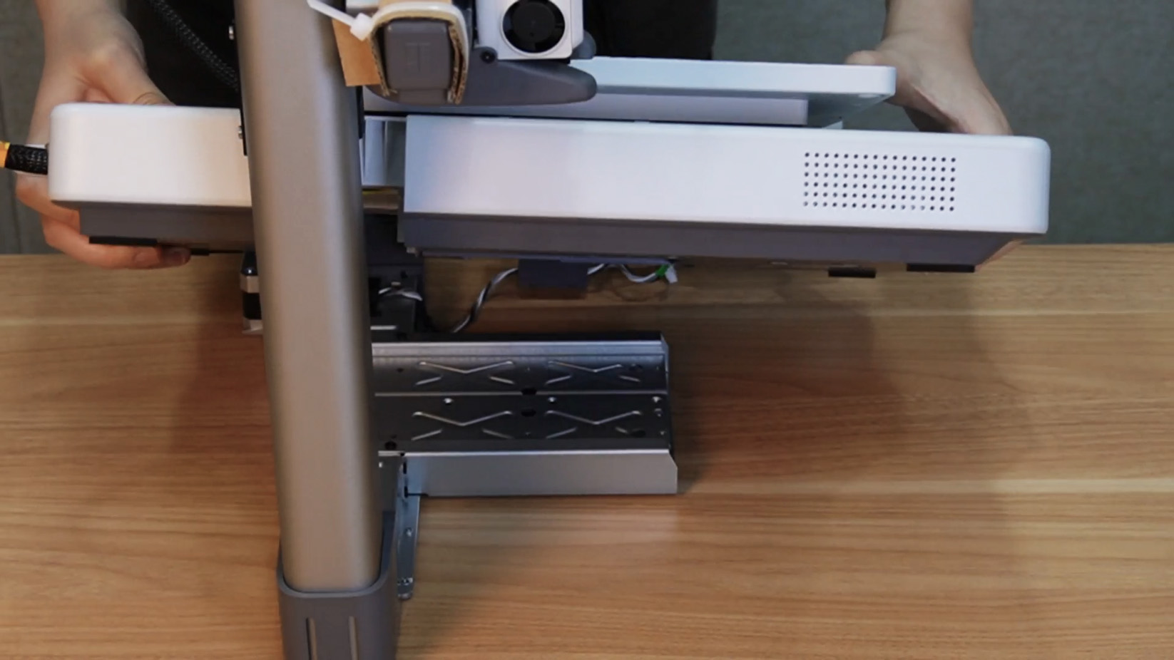 |
Step 7. Open the cable slot, remove the yellow cable, and use tape to secure the cable box to the printer frame.
 |
 |
 |
¶ Secure the heatbed
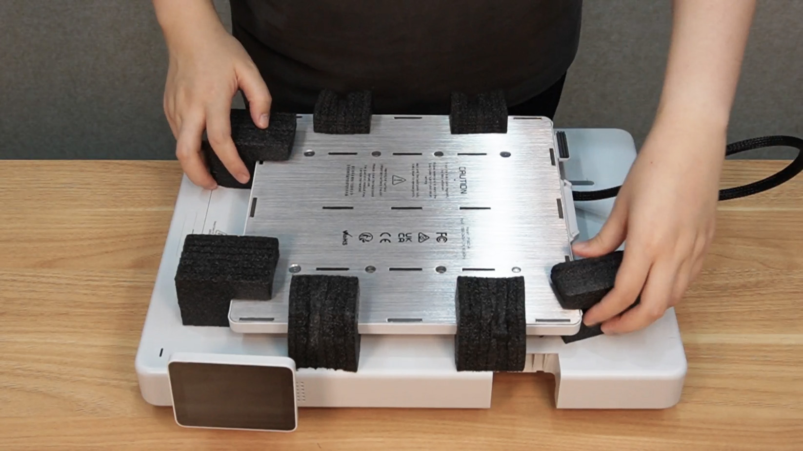
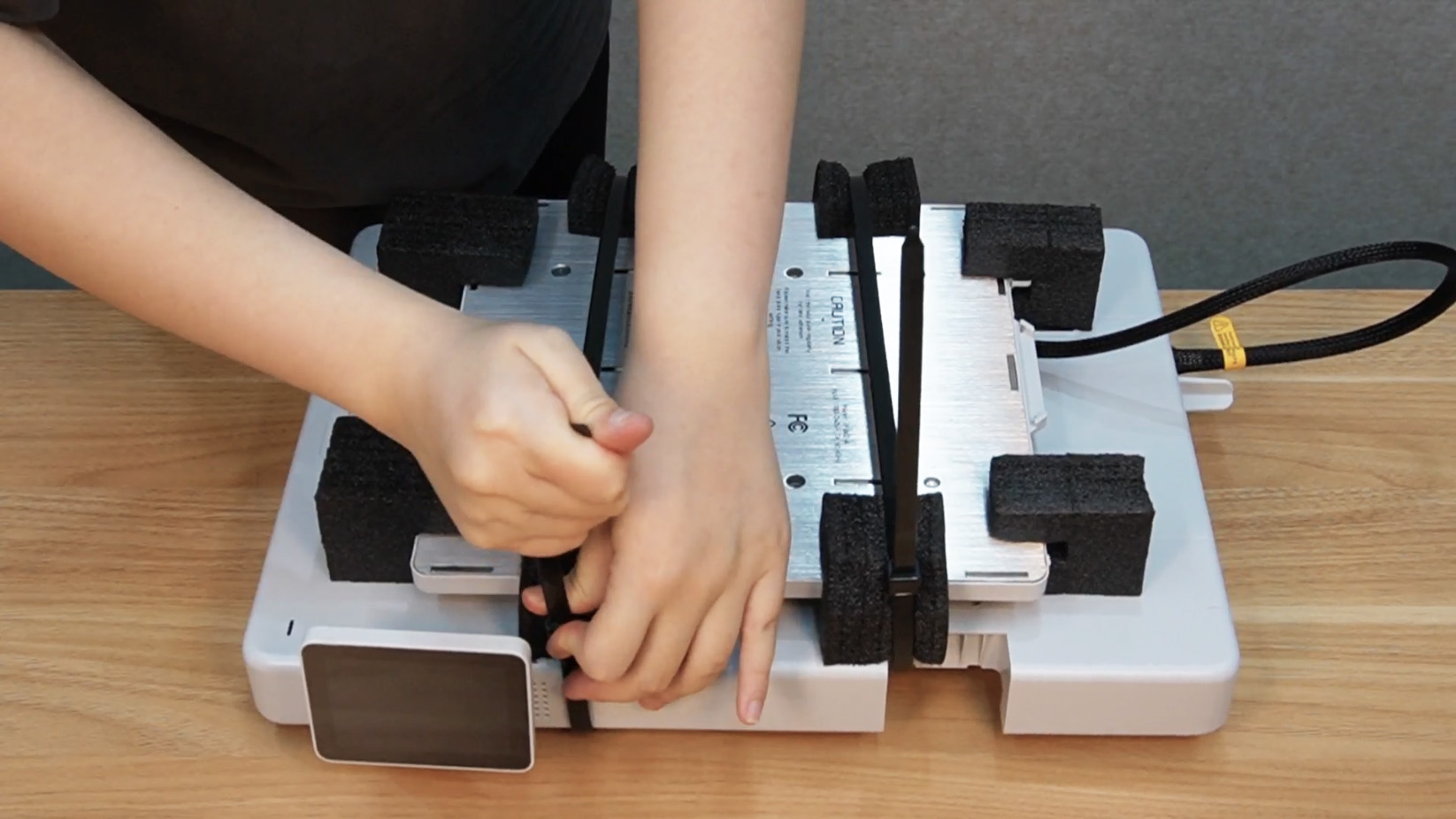
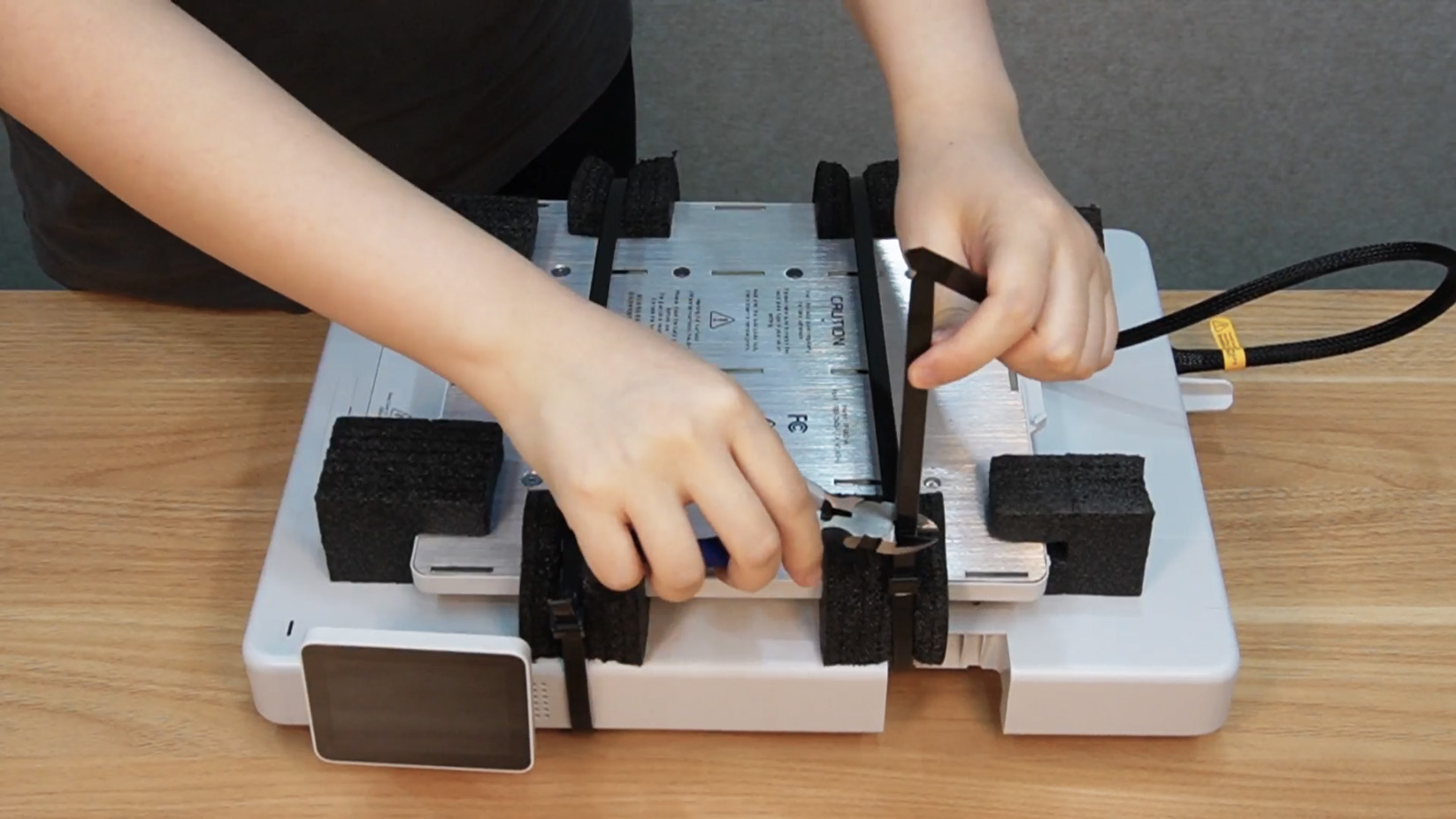
Step 1. Place the heatbed protective foam, secure it with cable ties, and cut off excess cable ties.
 |
 |
 |
Step 2. Place the printer base back into the foam box.
 |
 |
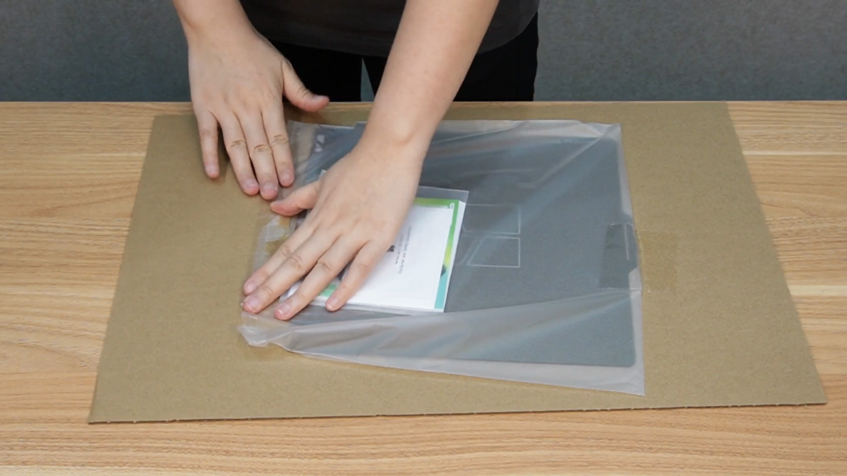
Step 3. Put the build plate and purge wiper back into the packaging and secure them with tape.
 |
 |
 |
¶ Packing
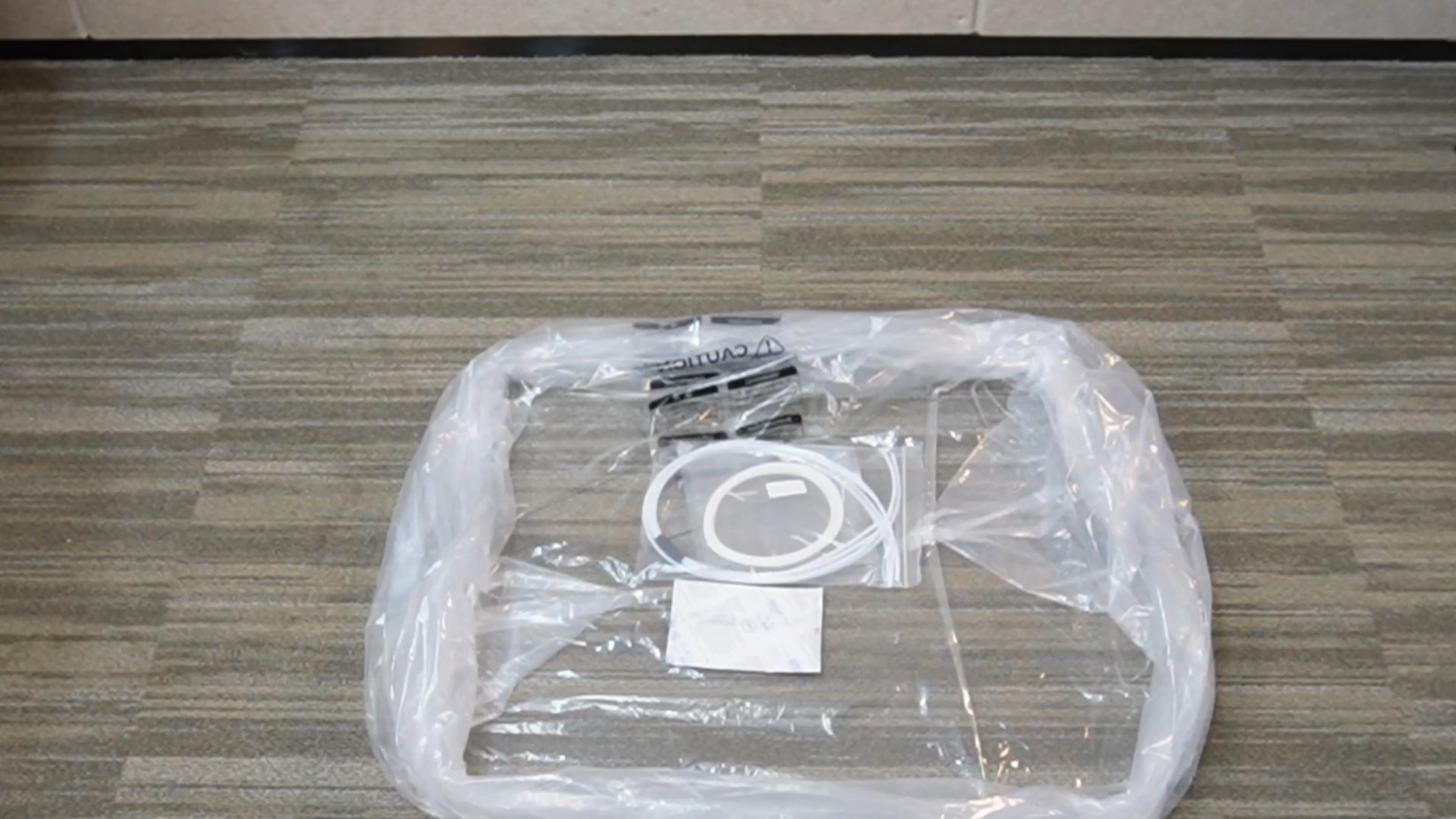
Step 1. Spread the waterproof bag on the ground, put accessories and screws removed above into package bags, and place them at the bottom.
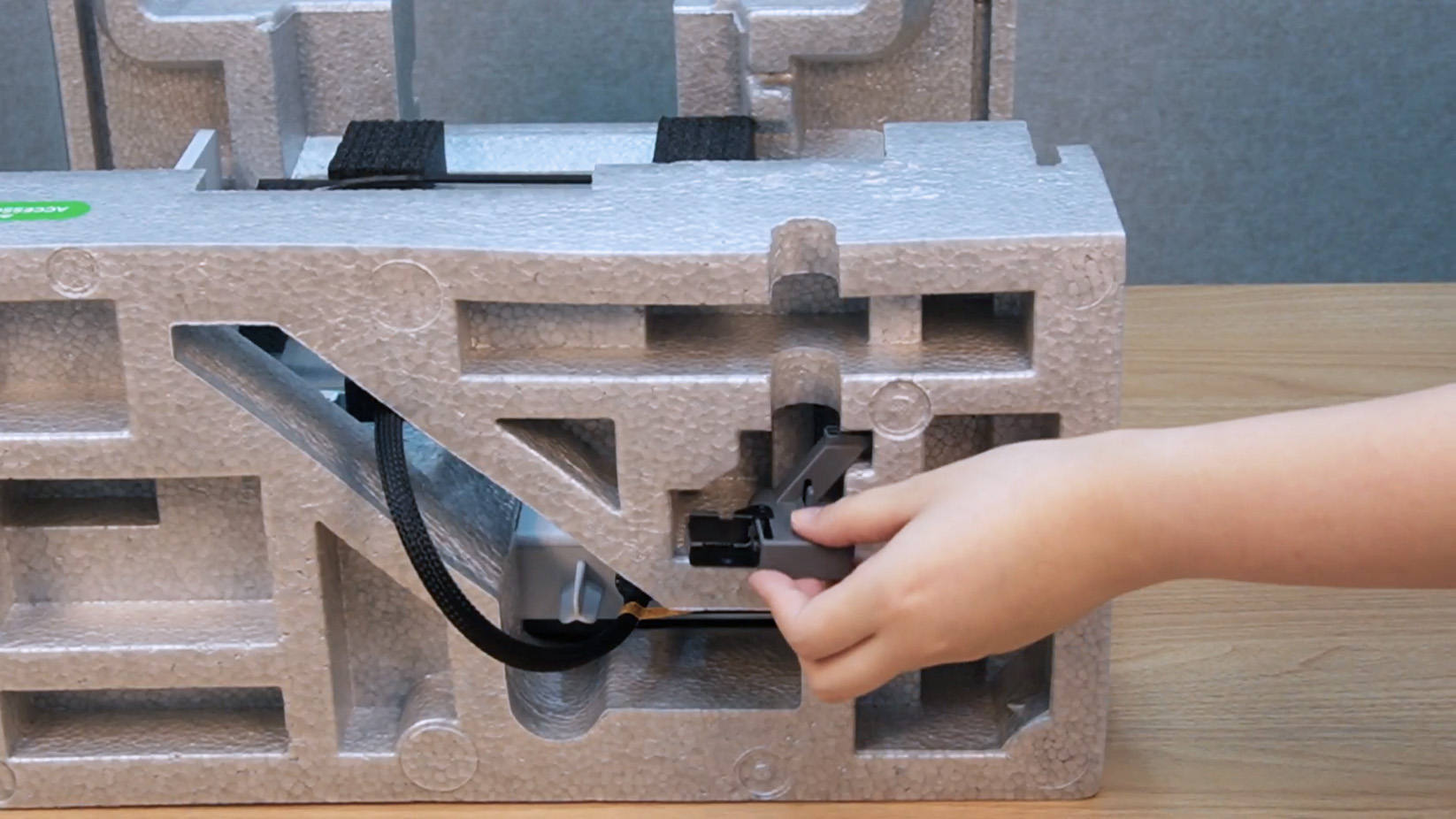
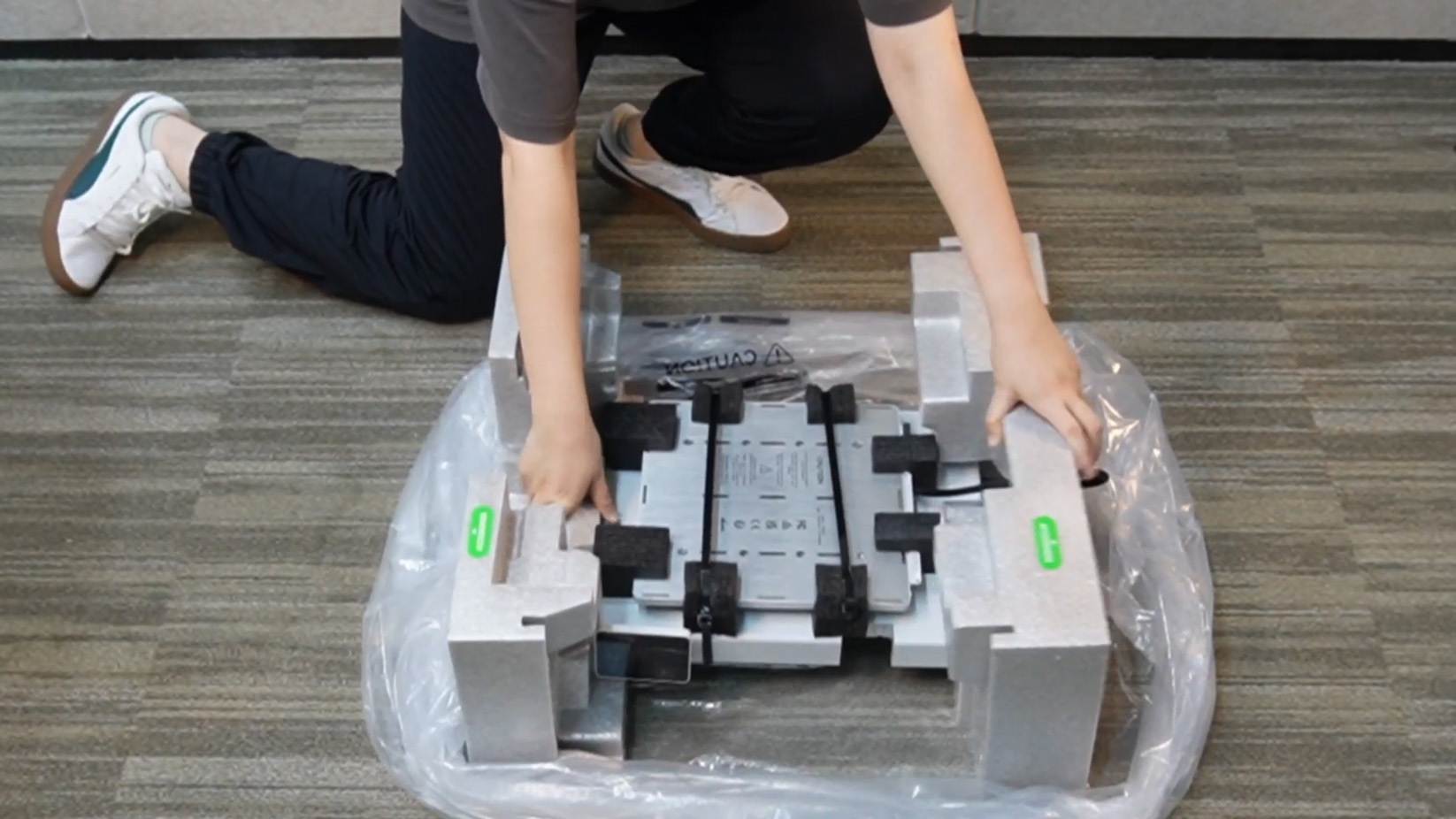
Step 2. Place the printer base into the bag and place the power cord into the side foam slot.
 |
 |
Step 3. Place the printer frame.
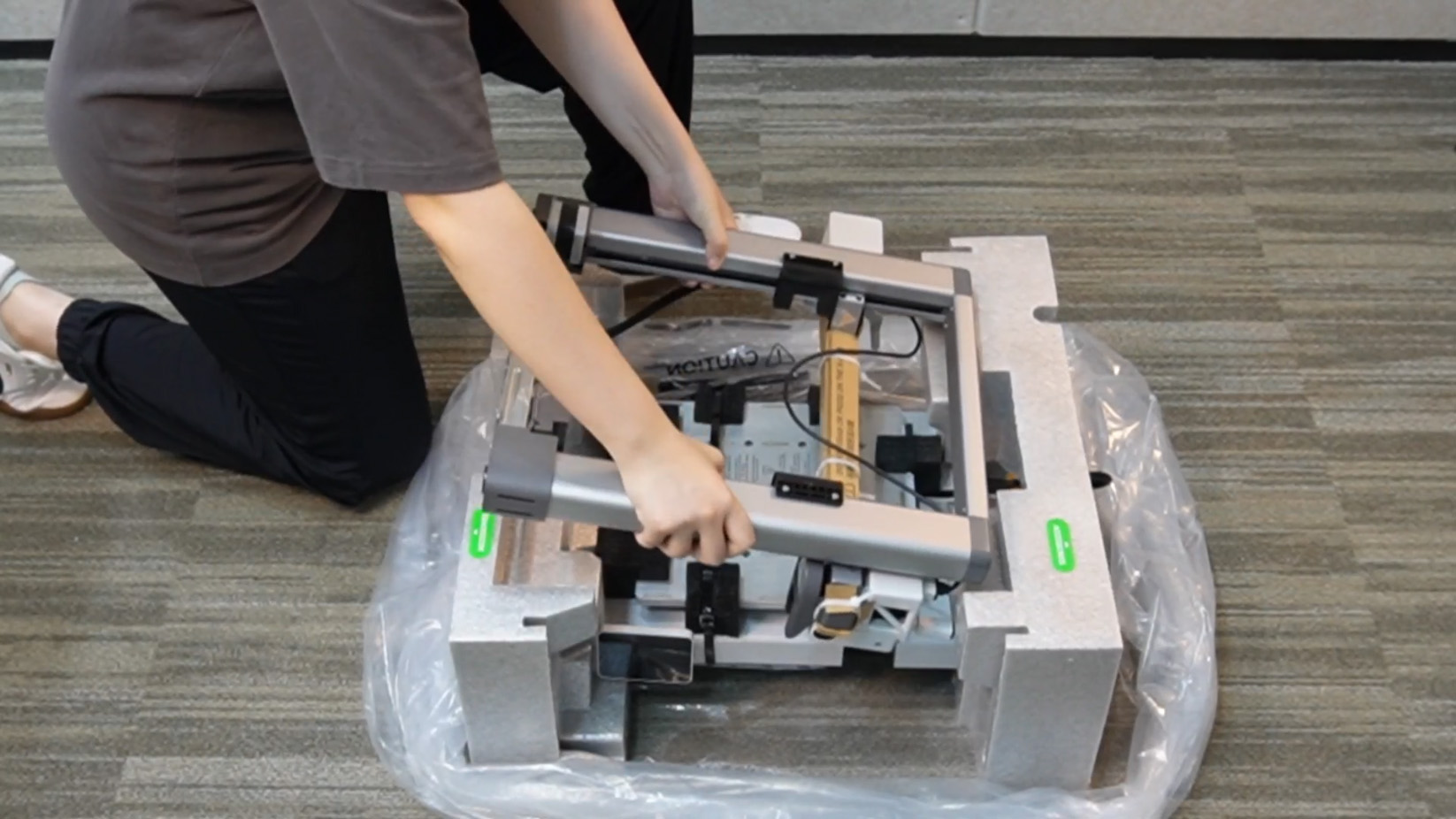
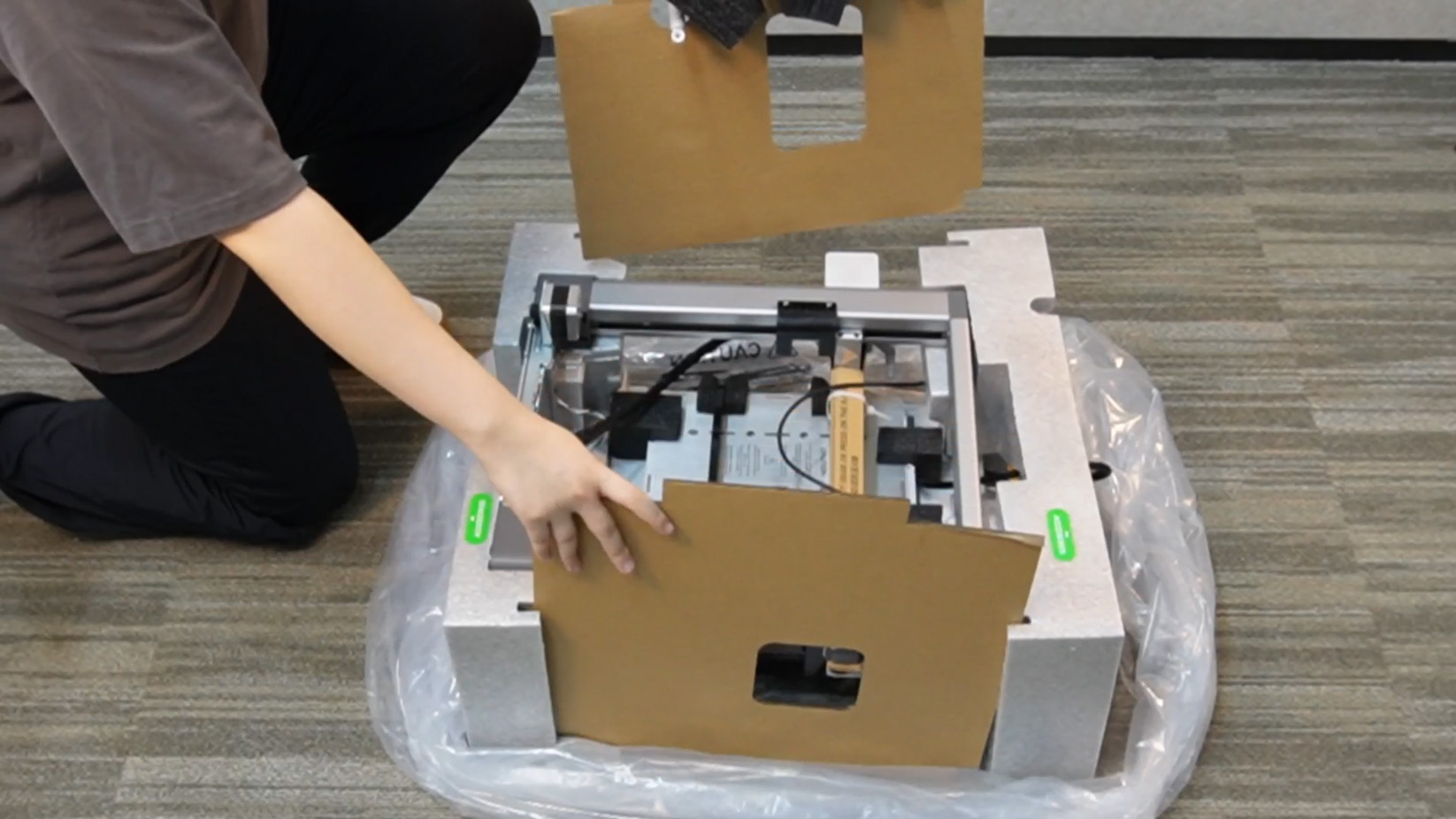
Step 4. Place two pieces of cardboard on the left and right, with the spool holder fixed on one of them.
 |
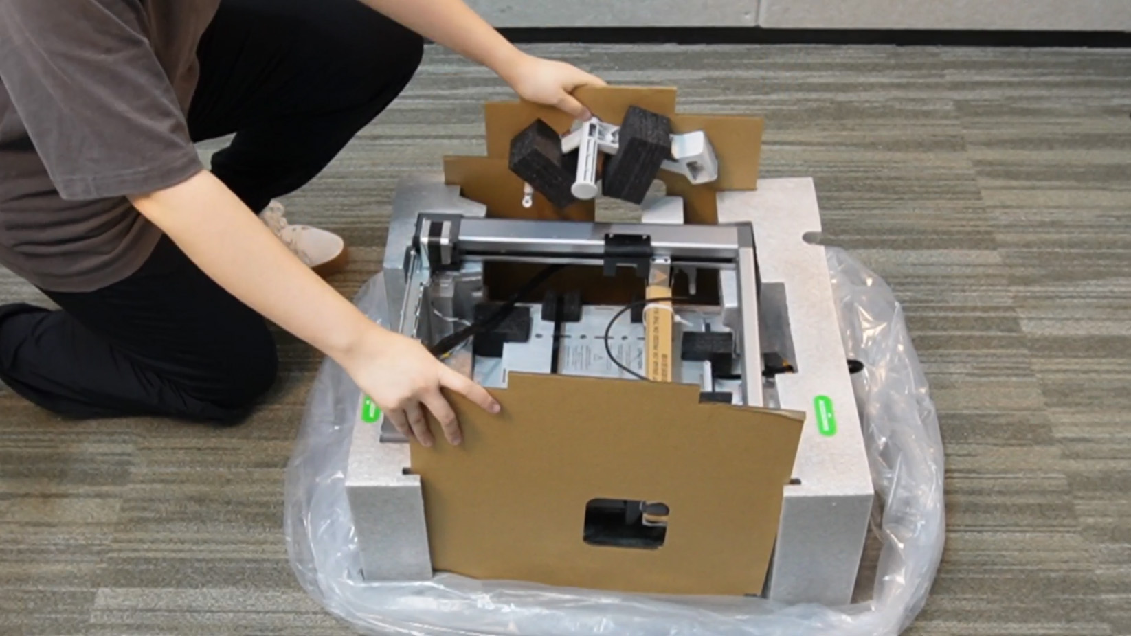 |
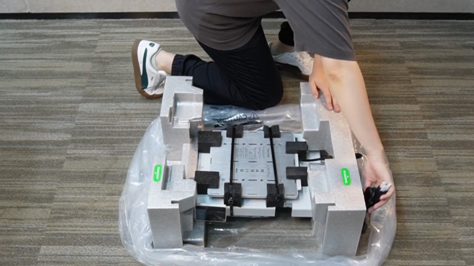
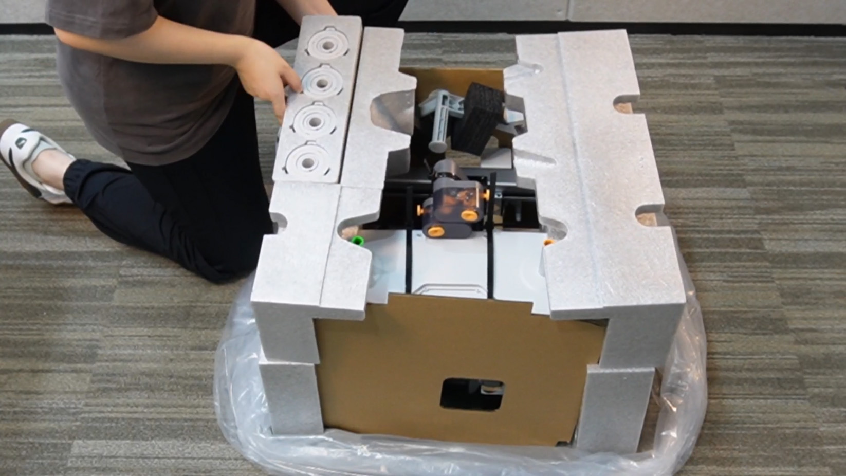
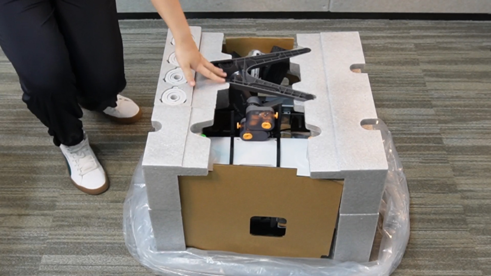
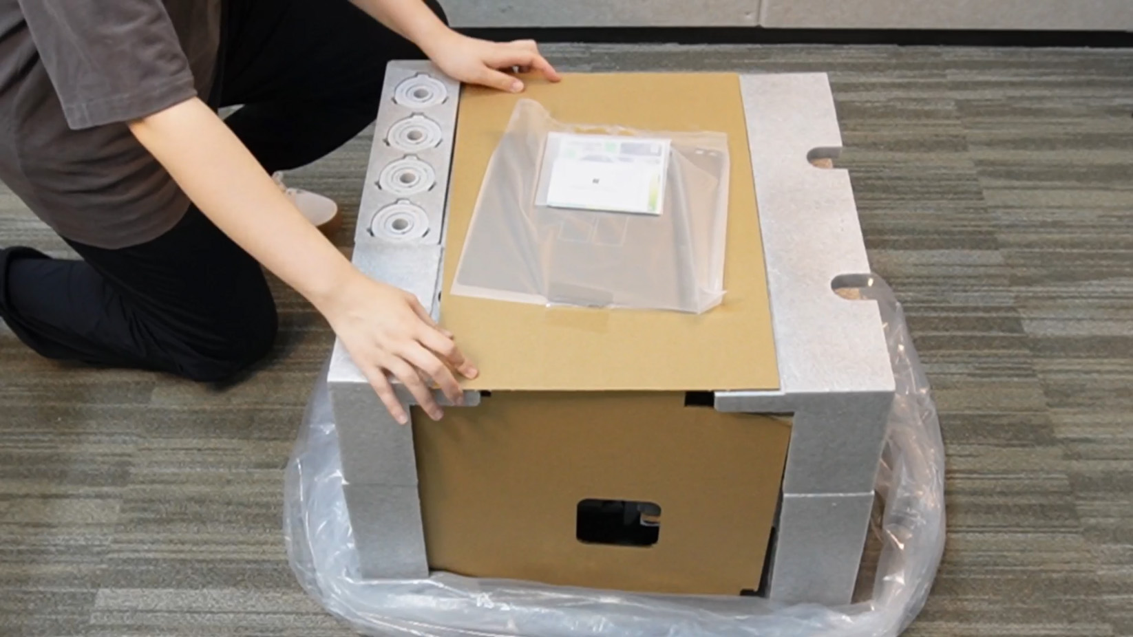
Step 5. Place the AMS lite, adjust the position of the components, place the AMS lite base upside down, and cover it with the cardboard with the build plate attached.
 |
 |
 |
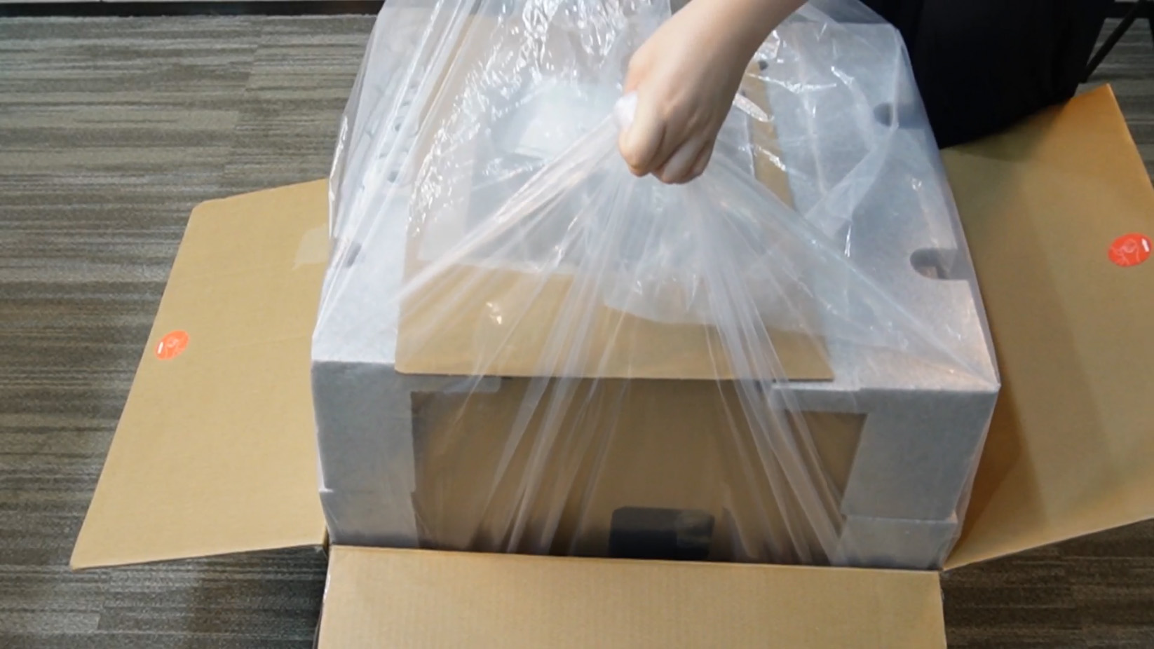
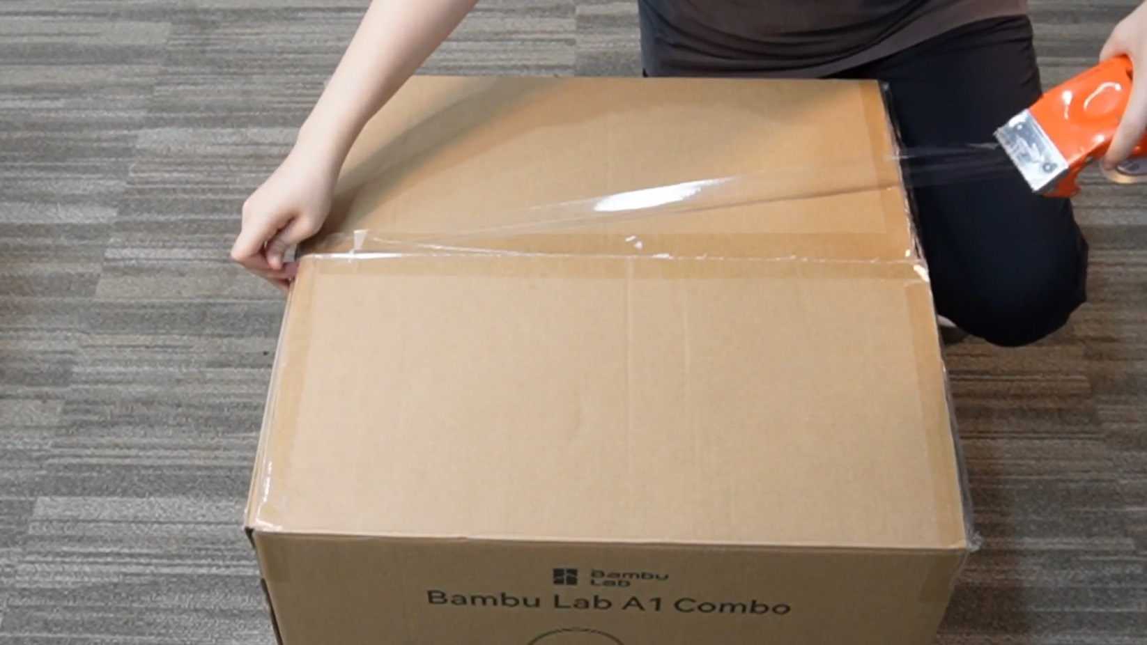
Step 6. Fold the waterproof bag, lift it up and put it into the packaging carton, and seal the carton with tape.
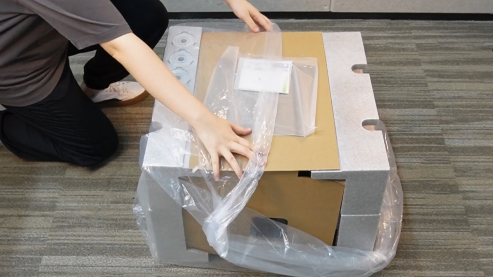 |
 |
 |
¶ End Notes
We hope the detailed guide provided has been helpful and informative.
If this guide does not solve your problem, please submit a support ticket. We will answer your questions and provide assistance.
If you have any suggestions or feedback on this Wiki, please leave a message in the comment area. Thank you for your support and attention!