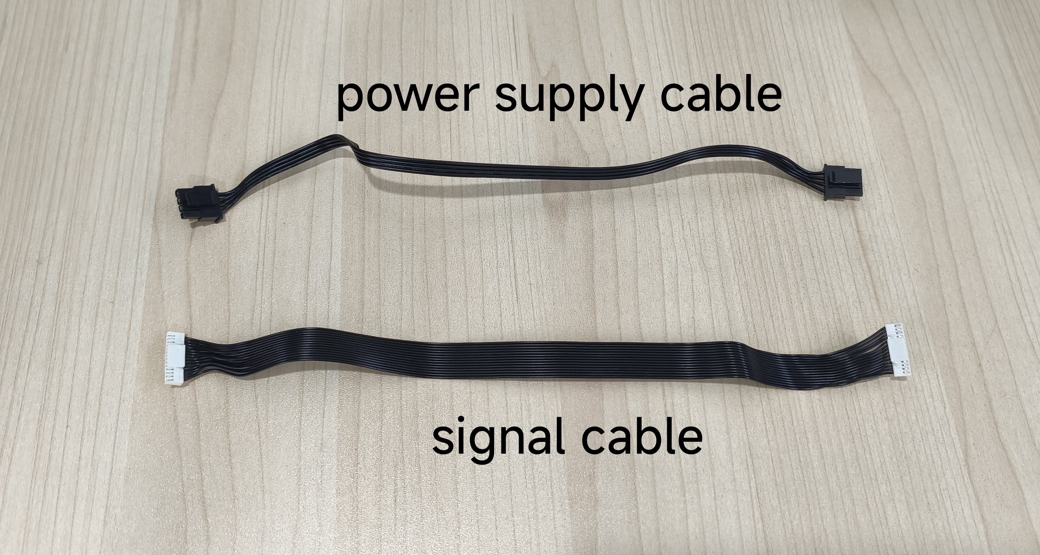
¶ AMS 2 Pro Cable Pack (6-in-1)
The pack includes 6 cables:
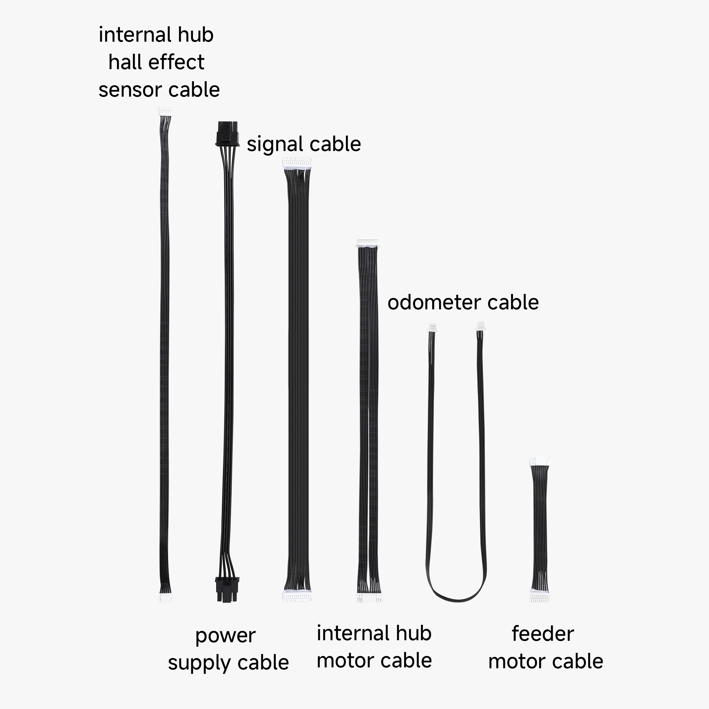
1 - Feeder Motor Cable*1
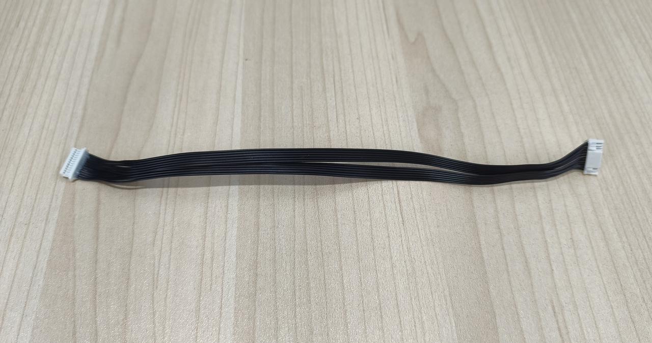
2 - Power Supply Cable*1
3 - Signal Cable*1
4 - Odometer Cable*1
5 - Internal Hub Motor Cable*1
6 - Internal Hub Hall Effect Sensor Cable*1
¶ When to Replace
If a cable is damaged during maintenance or becomes burnt during regular use, it should be replaced.
¶ Tools and Materials Needed
-
AMS 2 Pro Cable Pack
-
H2.0 Hex Key
-
H1.5 Hex Key
¶ Screw List
| Model | Position | |
|---|---|---|
| Screw A | BT3-8 | AMS 2 Pro main frame |
| Screw B | BT2-5 | AMS 2 Pro mainboard |
¶ Safety Warning
❗❗ IMPORTANT
It's crucial to disconnect the AMS 2 Pro from the printer before performing any maintenance work on the AMS 2 Pro and its electronics. Leaving the AMS connected while conducting such tasks can cause a short circuit, leading to additional electronic damage and safety hazards.
If you have any concerns or questions about following this guide, open a new ticket in our Support Page and we will do our best to respond promptly and provide you with the assistance you need.
¶ Remove AMS 2 Pro Main Frame Assembly
¶ Step 1 - Remove the PTFE Tube
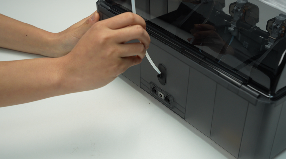
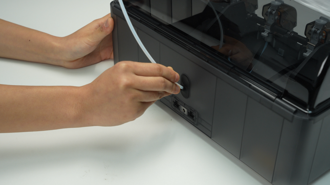
Press the button located on the filament hub to release the connector, then gently pull out the PTFE tube.
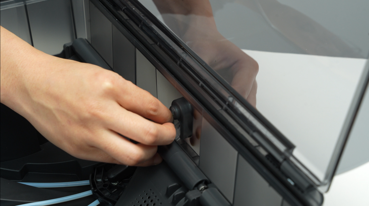
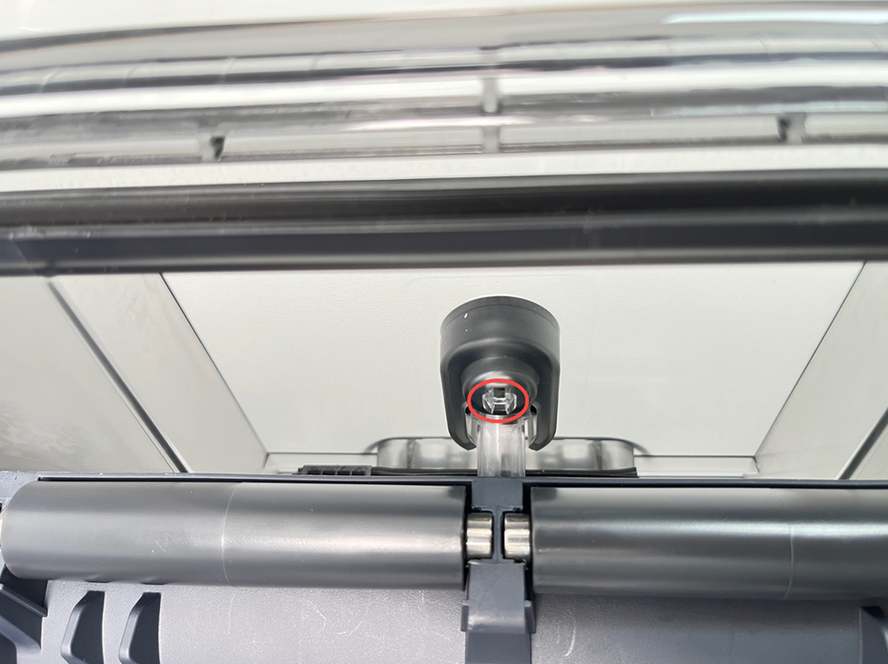
¶ Step 2 - Pull out the PTFE Tube Release Button
Pinch the clip from the inside of the lower cover to automatically pop open the PTFE tube release button, and then pull out the PTFE tube release button from the back of the AMS 2 Pro.
Notice:
When squeezing the buckle, use your other hand to hold the PTFE tube from the back of the AMS to release the switch to prevent the spring from being ejected and lost.
 |
 |
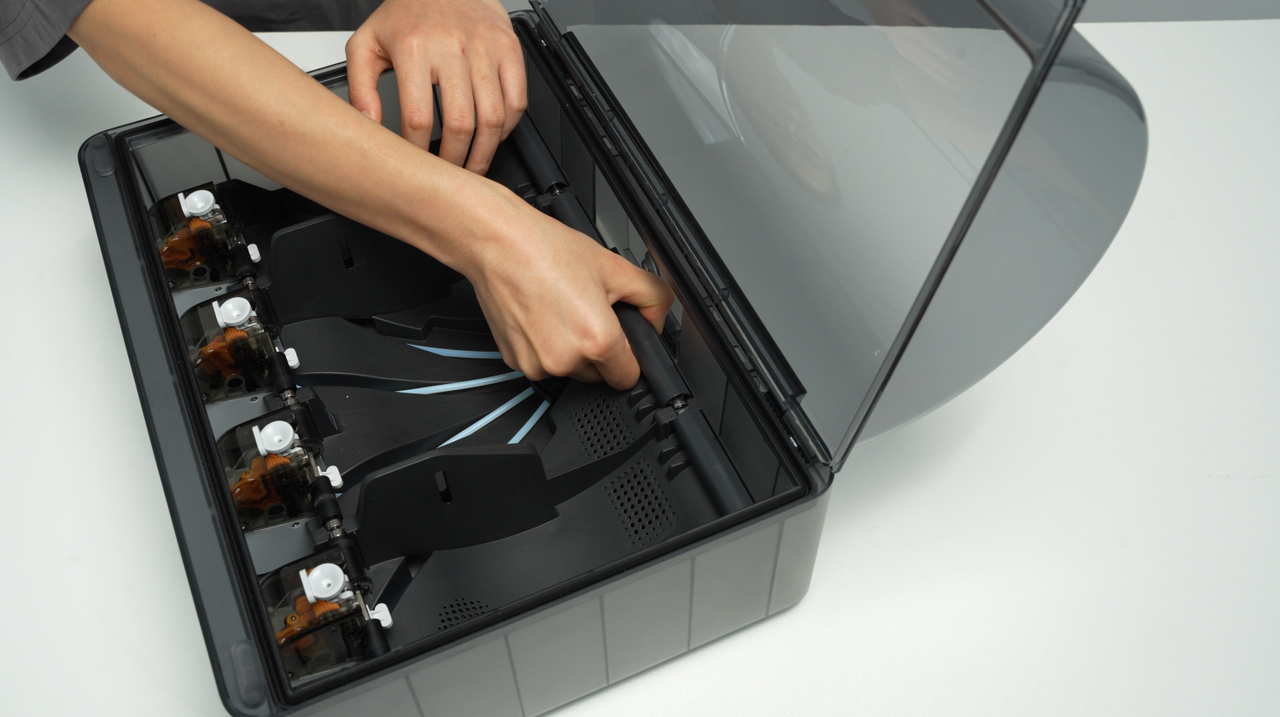
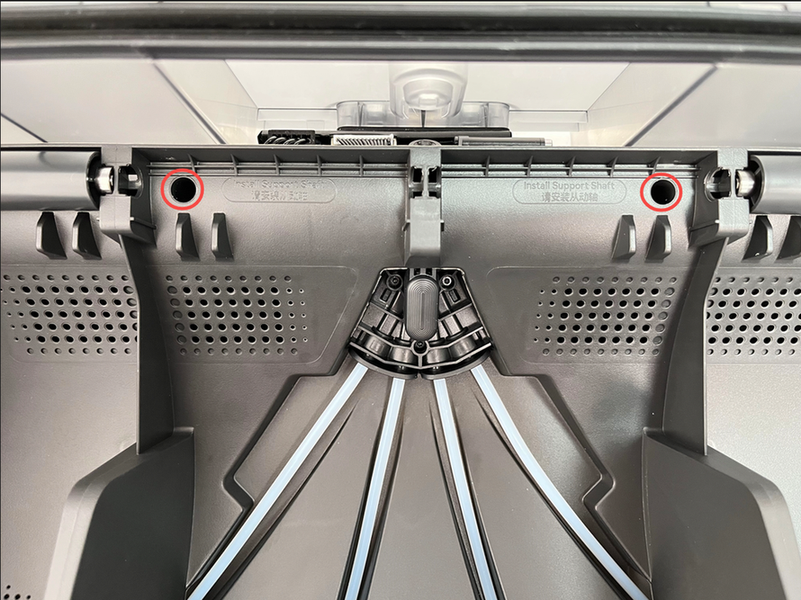
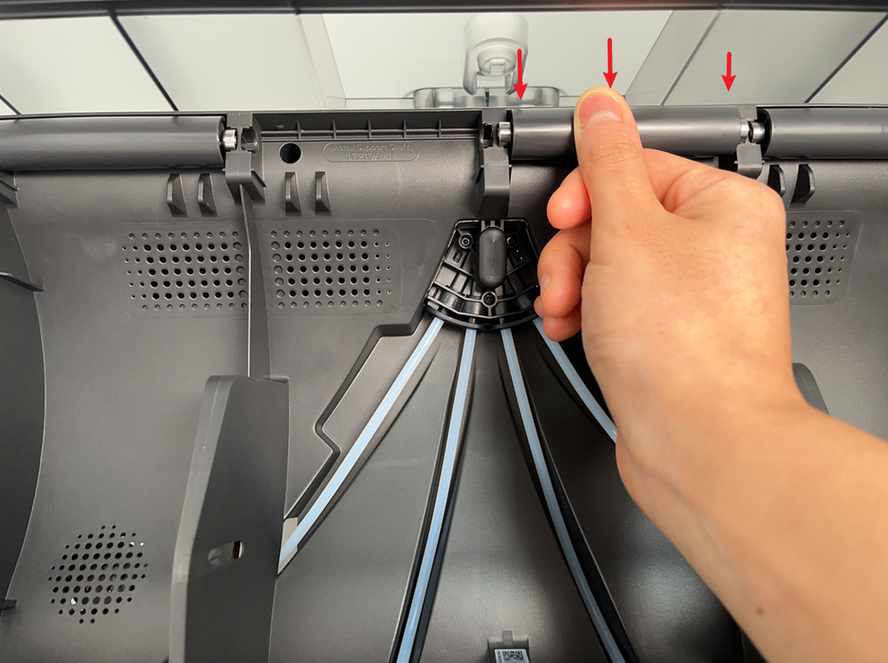
¶ Step 3 - Remove the AMS 2 Pro Main Frame Assembly
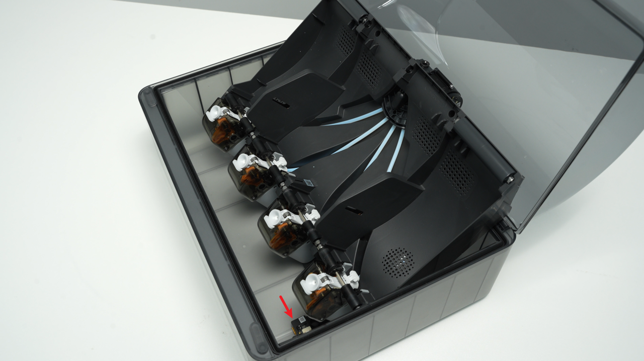
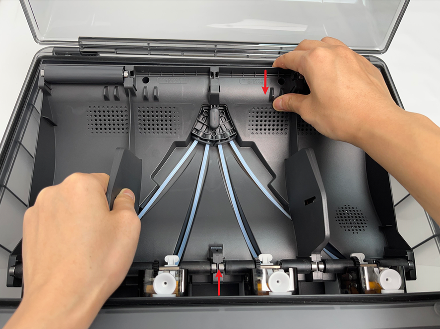
- Remove the driven support sleeve assembly of the two middle slots to expose the two screw holes. When removing the bearing sleeve, be careful with the bearings at both ends to avoid losing them.
 |
 |
- Remove the two screws A (BT3-8) that secure the AMS 2 Pro main frame.
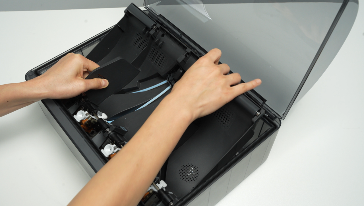
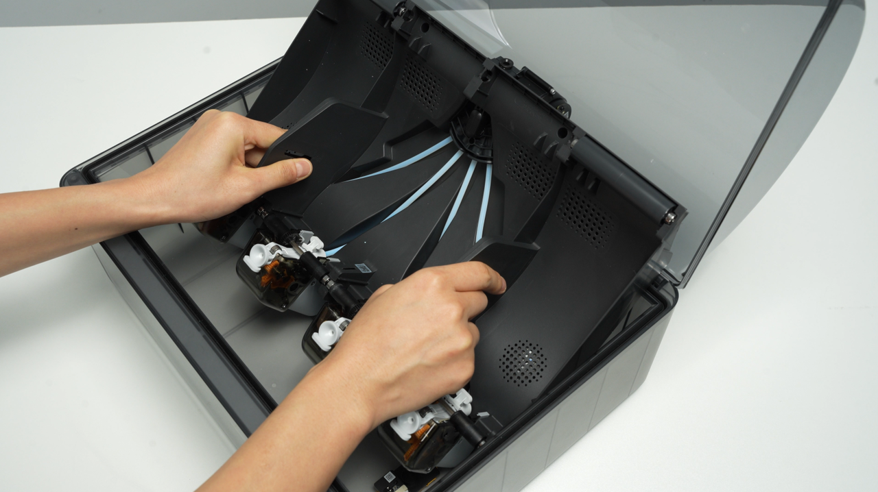
- Lift the rear part of the main frame completely and place it vertically on the lower cover of the AMS 2 Pro. Note that there are cables connected, so do not operate violently. When lifting, it is recommended to lift the front part of the main frame first, and then push it forward to make room for the rear part of the frame.
 |
 |
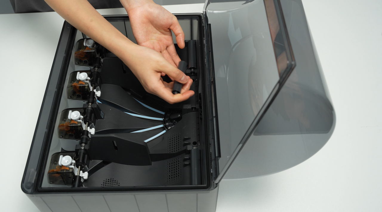
When placing the AMS 2 Pro main frame vertically, avoid the electronic components of the vent to prevent them from being crushed.
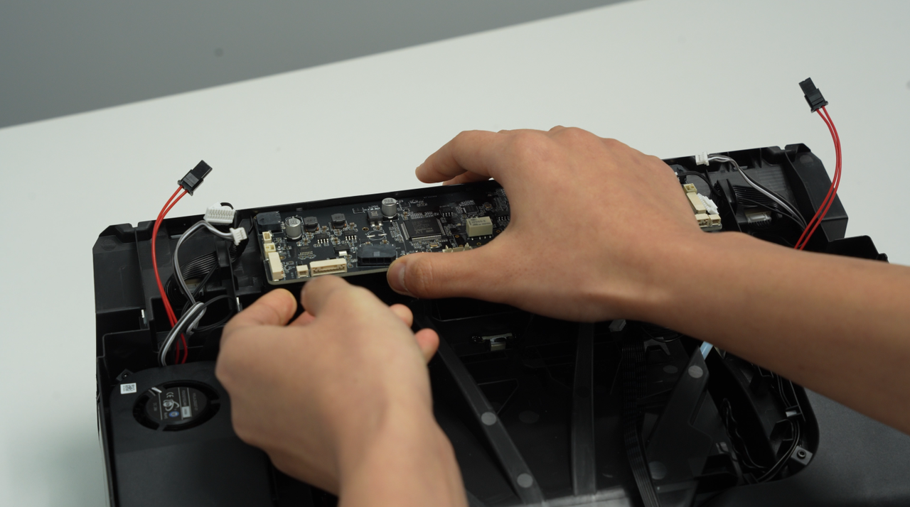
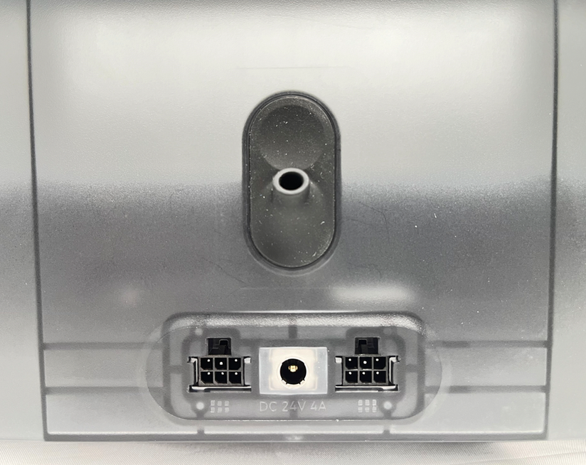
- Unlock the plug buckle, unplug the signal cable and power cable on the AMS 2 Pro power board, and lift out the AMS 2 Pro main frame assembly as a whole.
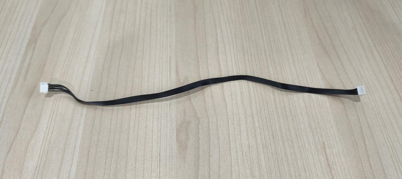
¶ Replace Power Supply Cable and Signal Cable
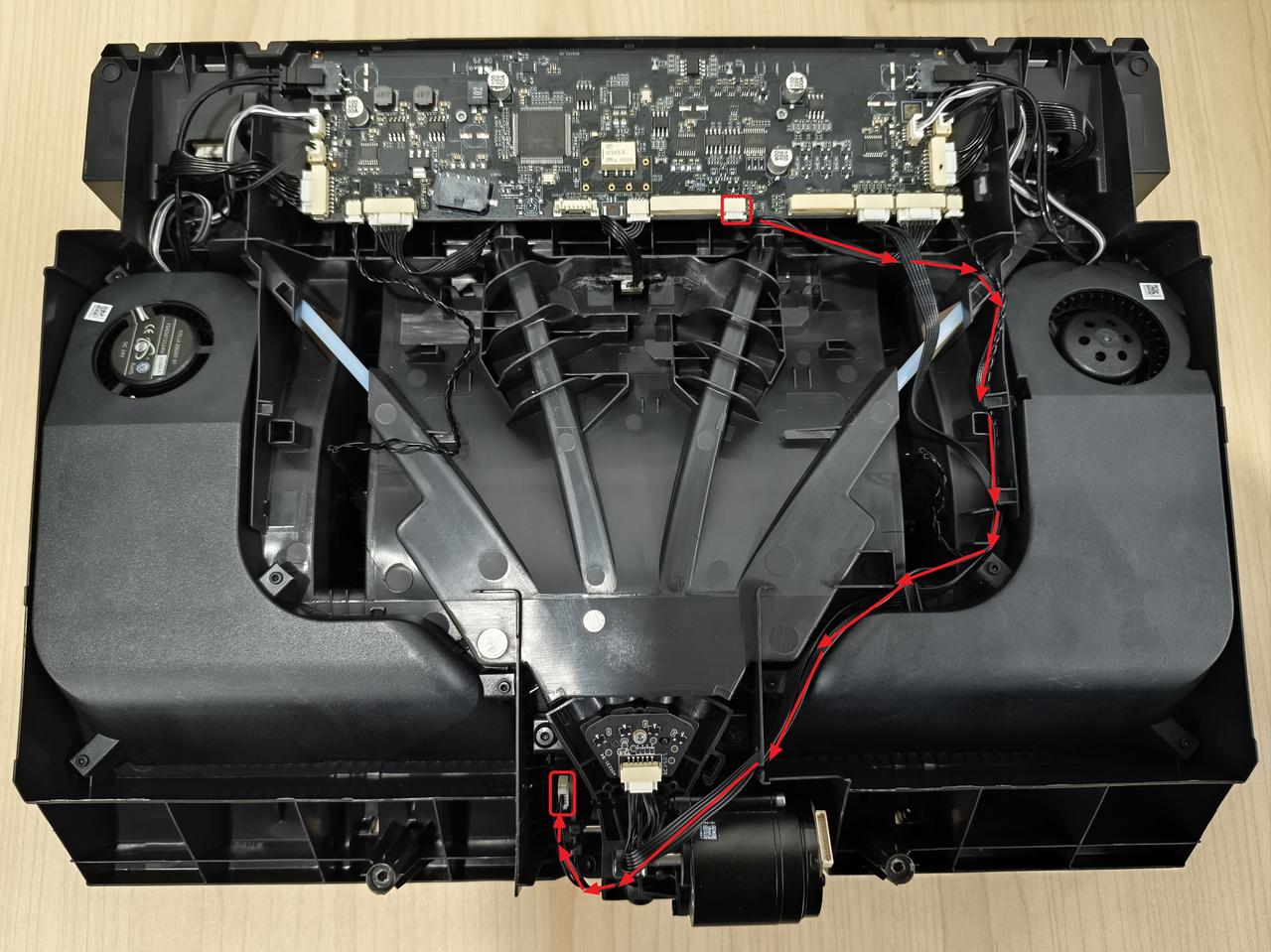
¶ Step 1 - Remove Power Supply Cable and Signal Cable
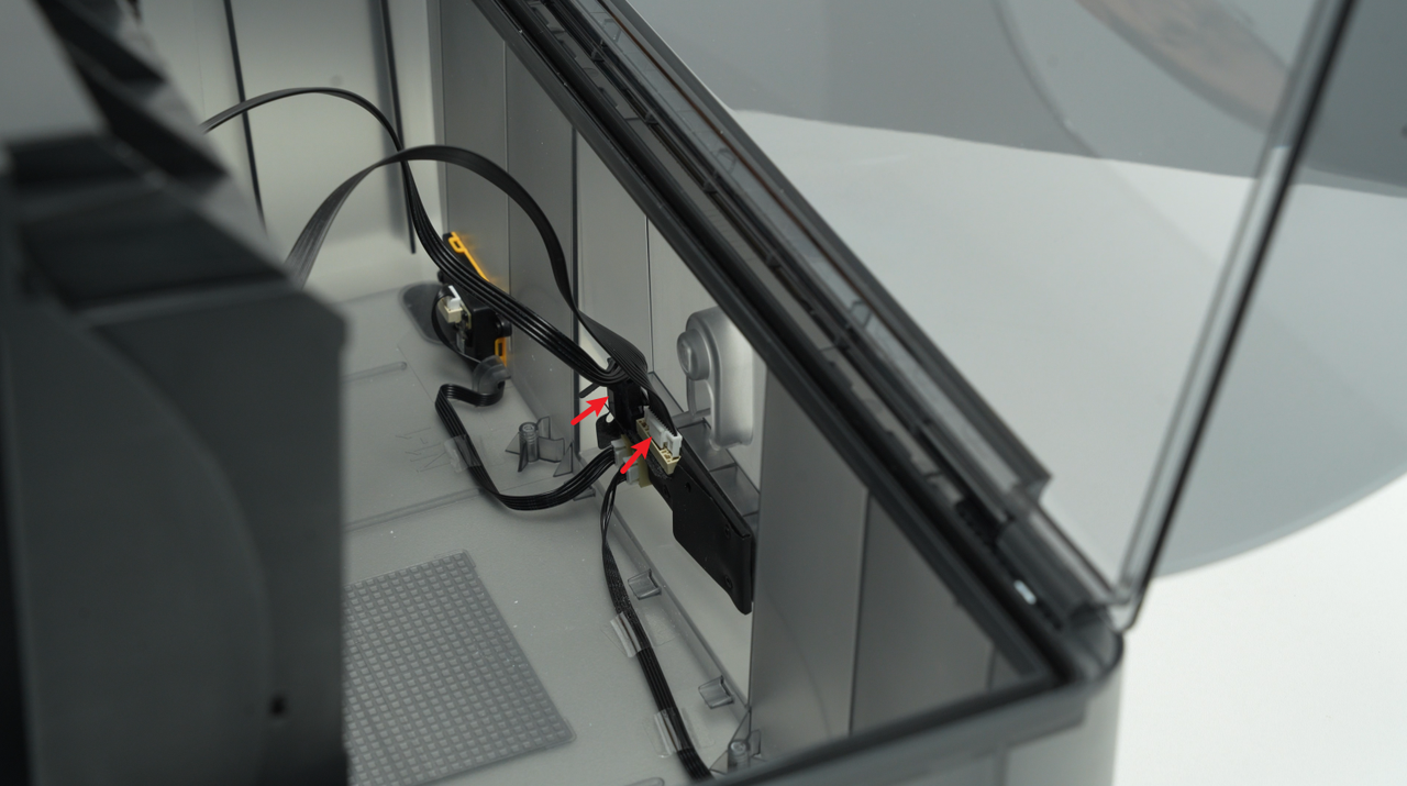
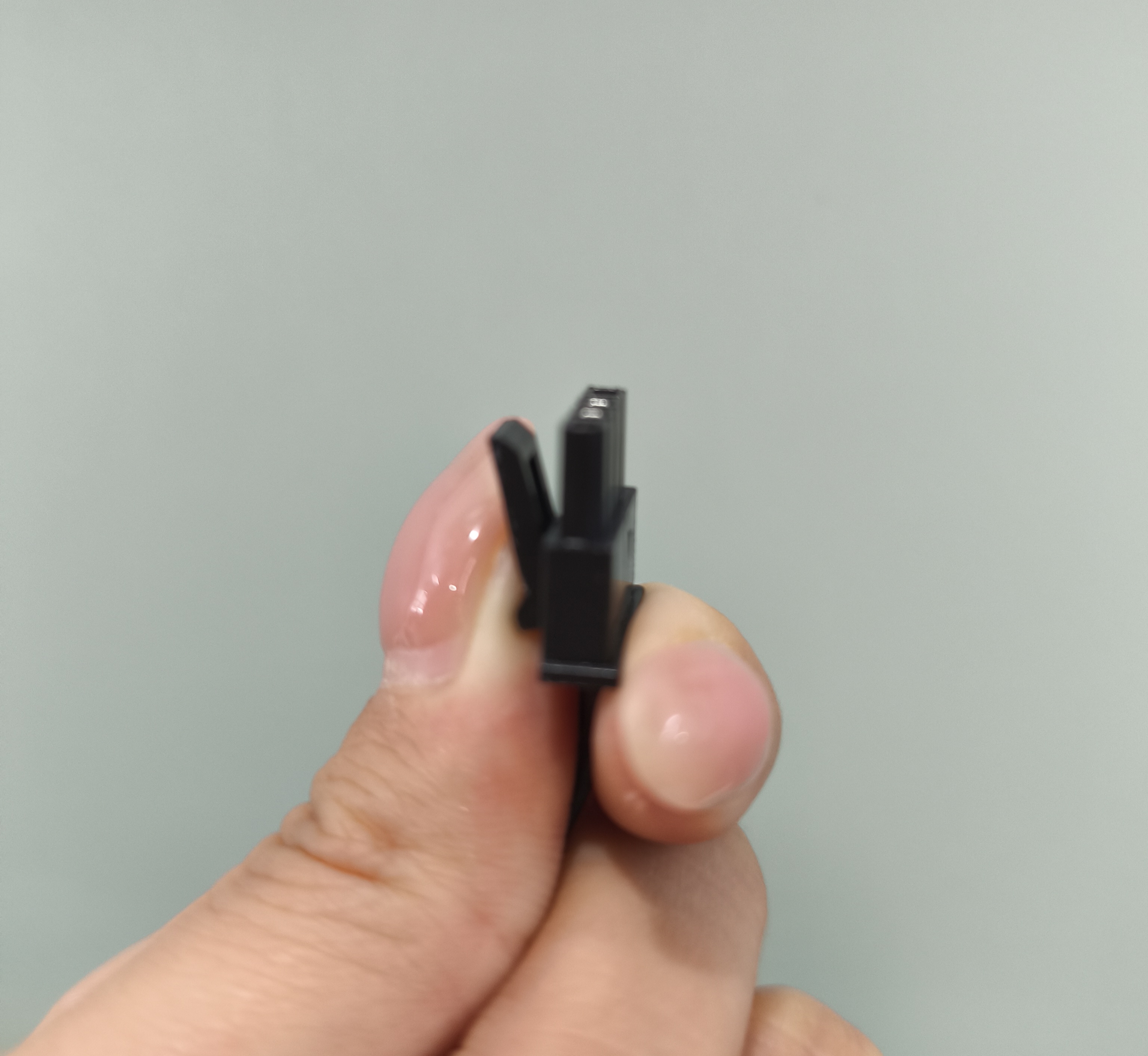
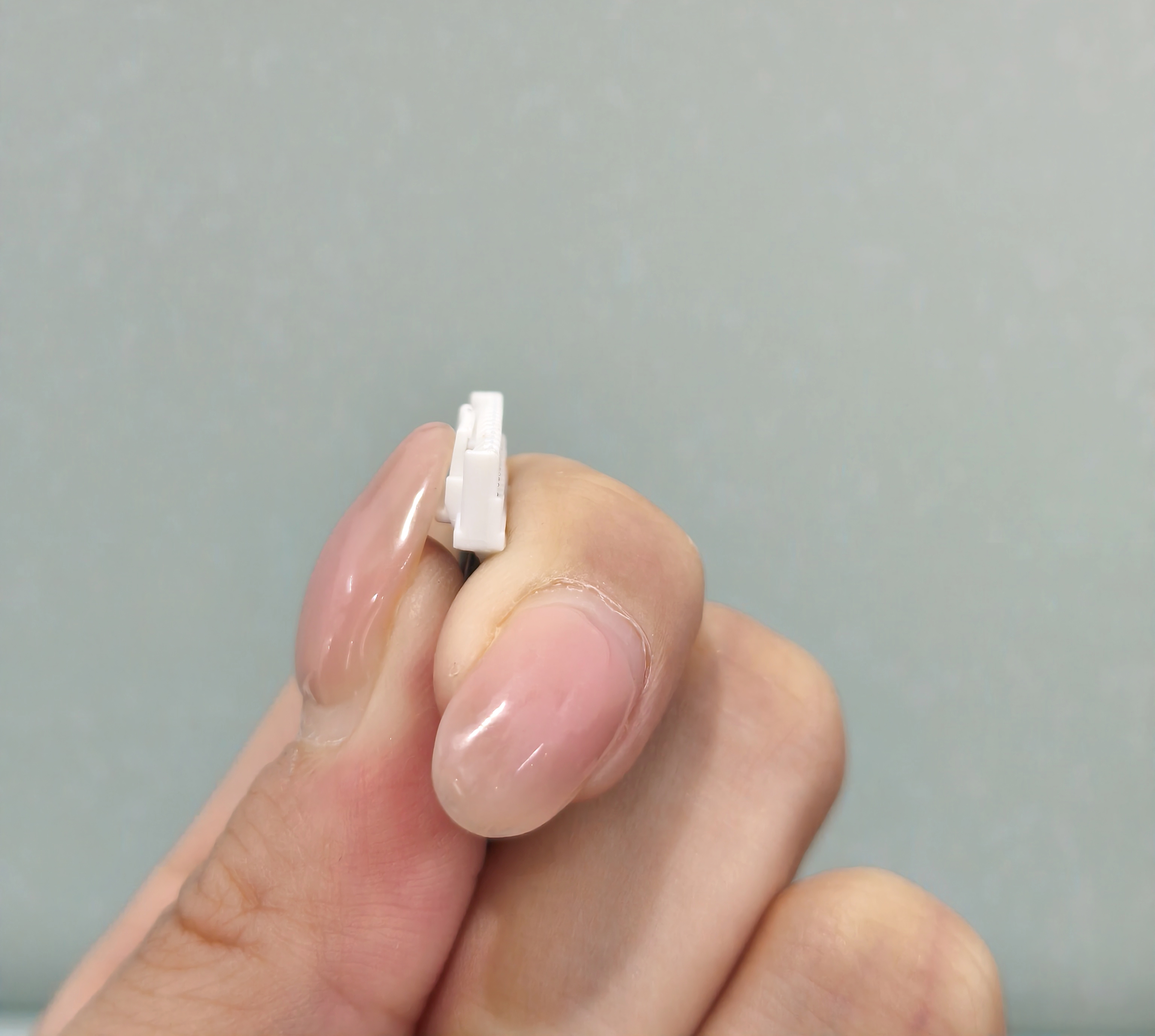
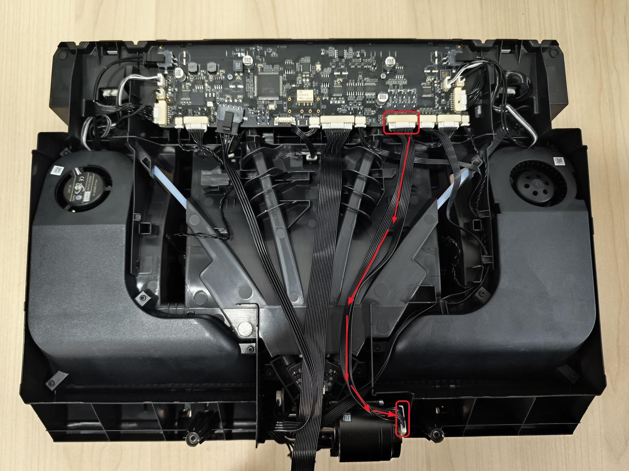
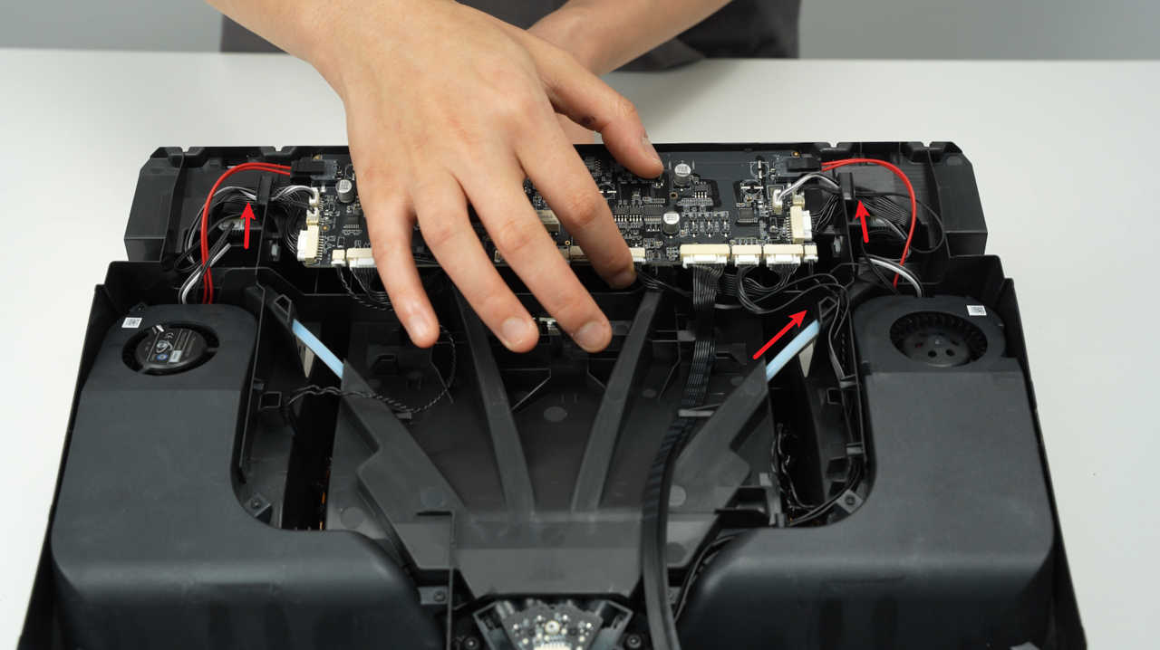
Find the connectors for power supply cable and signal cable (red box area) on the main board and disconnect them.
.jpg)
You need to press the area marked in the blue box and apply slight pressure to more easily unplug the connector. The pressing position is shown in the figure below.
 |
 |
¶ Step 2 - Connect Power Supply Cable and Signal Cable
Connect the new power supply cable and signal cable to the corresponding connectors on the AMS 2 Pro mainboard in sequence.
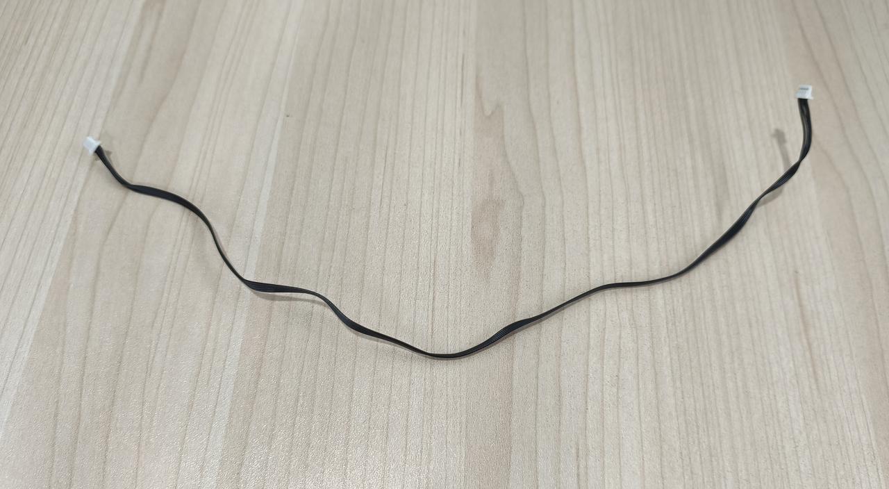
¶ Replace Internal Hub Motor Cable
¶ Step 1 - Remove Internal Hub Motor Cable
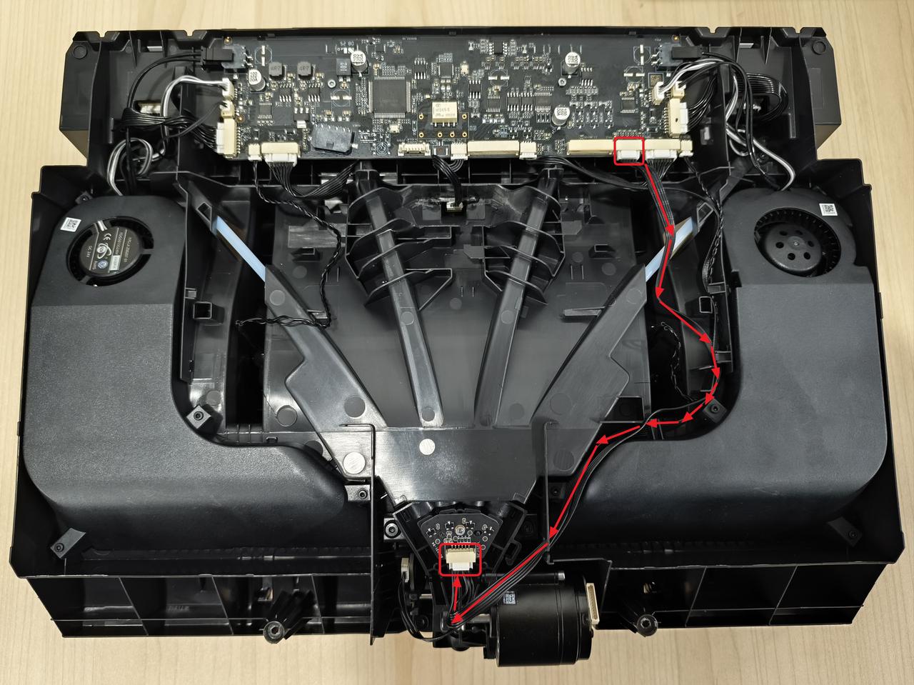
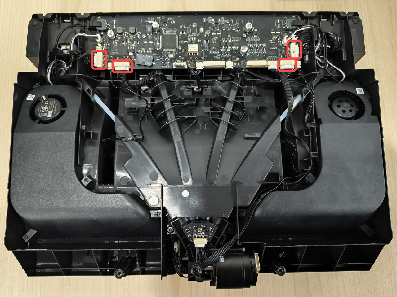
Find the two connectors for internal hub motor cable (red box area) on the main board and the internal hub unit, then disconnect them.
¶ Step 2 - Connect Internal Hub Motor Cable
Connect the new internal hub motor cable to the corresponding connectors on the AMS 2 Pro mainboard and the internal hub unit.
¶ Replace Internal Hub Hall Effect Sensor Cable
¶ Step 1 - Remove Internal Hub Hall Effect Sensor Cable
First, disconnect the internal hub hall effect sensor cable from the mainboard connector. Then, pull the cable out from the cable channel, and finally disconnect it from the internal hub hall effect sensor connector.
¶ Step 2 - Connect Internal Hub Hall Effect Sensor Cable
Connect the new internal hub hall effect sensor cable to the corresponding connectors on the AMS 2 Pro mainboard and the internal hub hall effect sensor in sequence, and arrange the cable properly within the cable channel.
¶ Replace Odometer Cable
¶ Step 1 - Remove Odometer Cable
Find two connectors of the odometer cable (red box area), disconnect them one by one, and pull the cable out from the cable channel.
¶ Step 2 - Connect Odometer Cable
Connect the new odometer cable to the corresponding connectors on the AMS 2 Pro mainboard and the odometer in sequence, and arrange the cable properly within the cable channel.
¶ Replace Feeder Motor Cable
AMS 2 Pro has four feeder motor cables, which you can replace as needed.
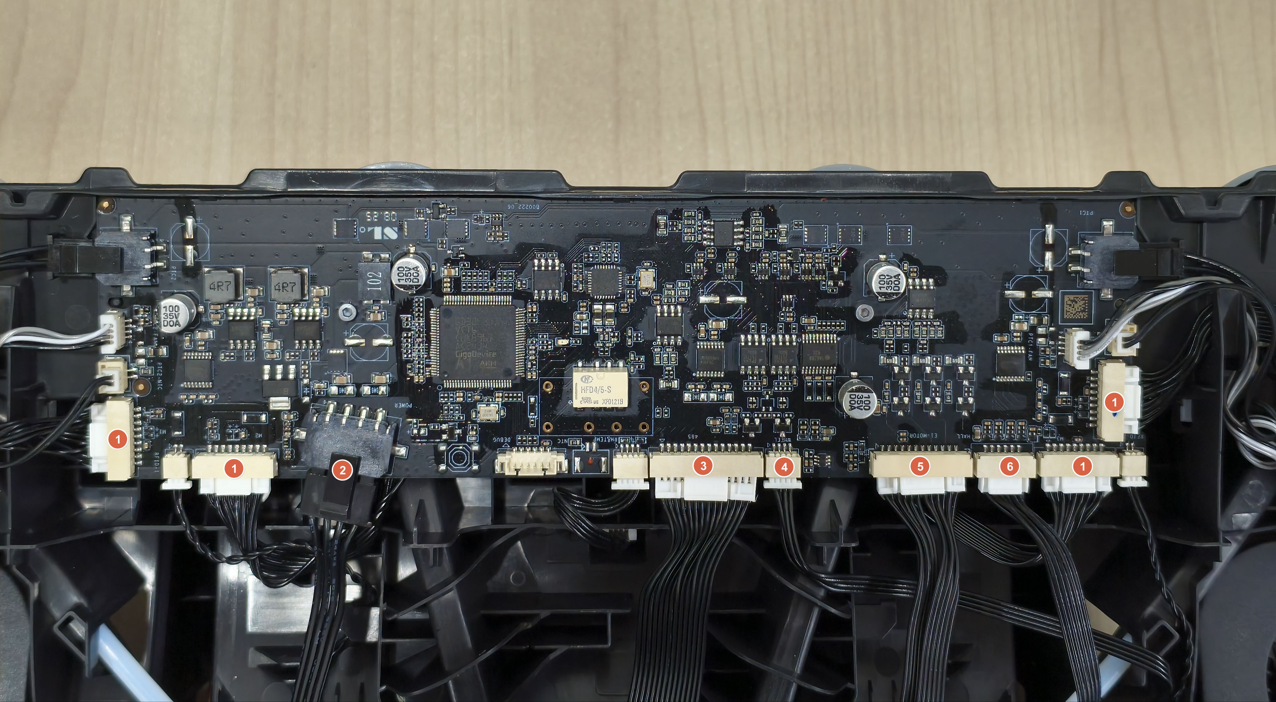
¶ Step 1 - Remove the AMS 2 Pro Mainboard
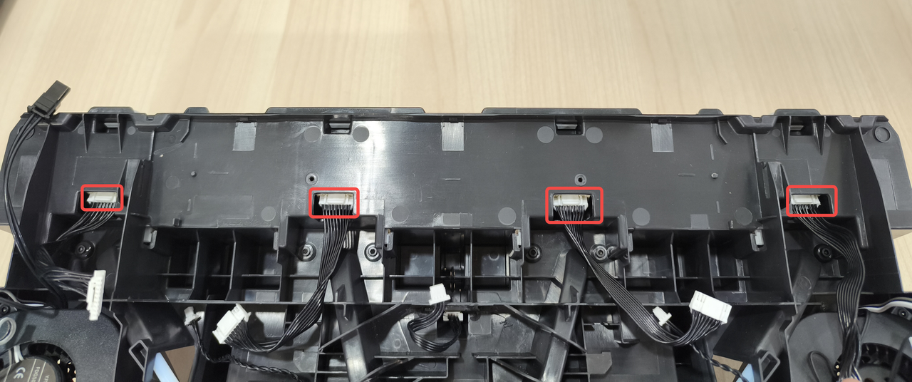
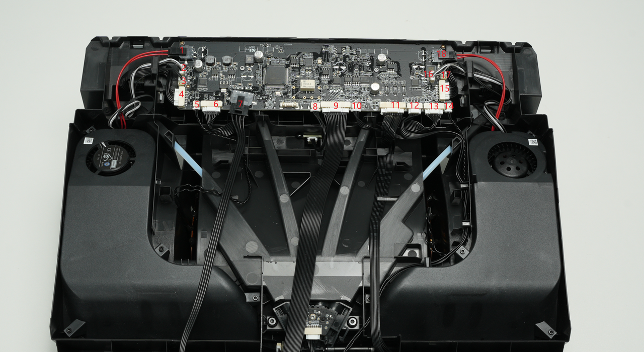
- Disconnect 18 cables from the AMS 2 Pro mainboard. Before disconnecting, you can take a photo of the cable connections to help with reconnection later.

- The AMS 2 Pro mainboard is secured by 2 screws B (BT2-5) and 5 clips. Remove the two screws with an H1.5 hex key.
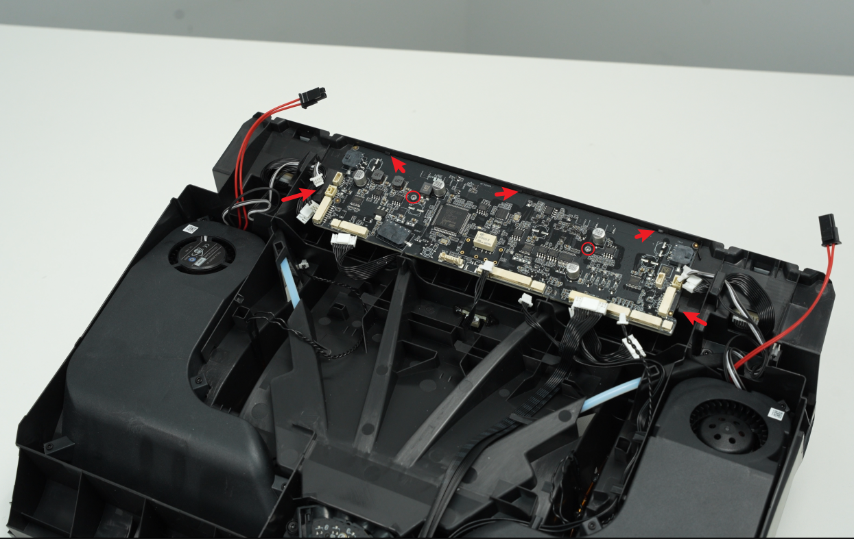
- After removing the 2 screws, gently pull the leftmost clip outward, lift the AMS 2 Pro mainboard from the bottom, and remove the mainboard.
 |
 |
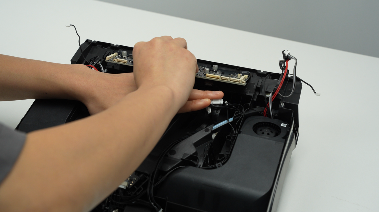
¶ Step 2 - Remove Feeder Motor Cable
After removing the mainboard, you will see the other connectors of the four feeder motor cables.
Unplug the connector of the feeder motor cable that needs to be replaced.
¶ Step 3 - Connect Feeder Motor Cable
Insert one end of the new feeder motor cable.
¶ Step 4 - Install the Mainboard
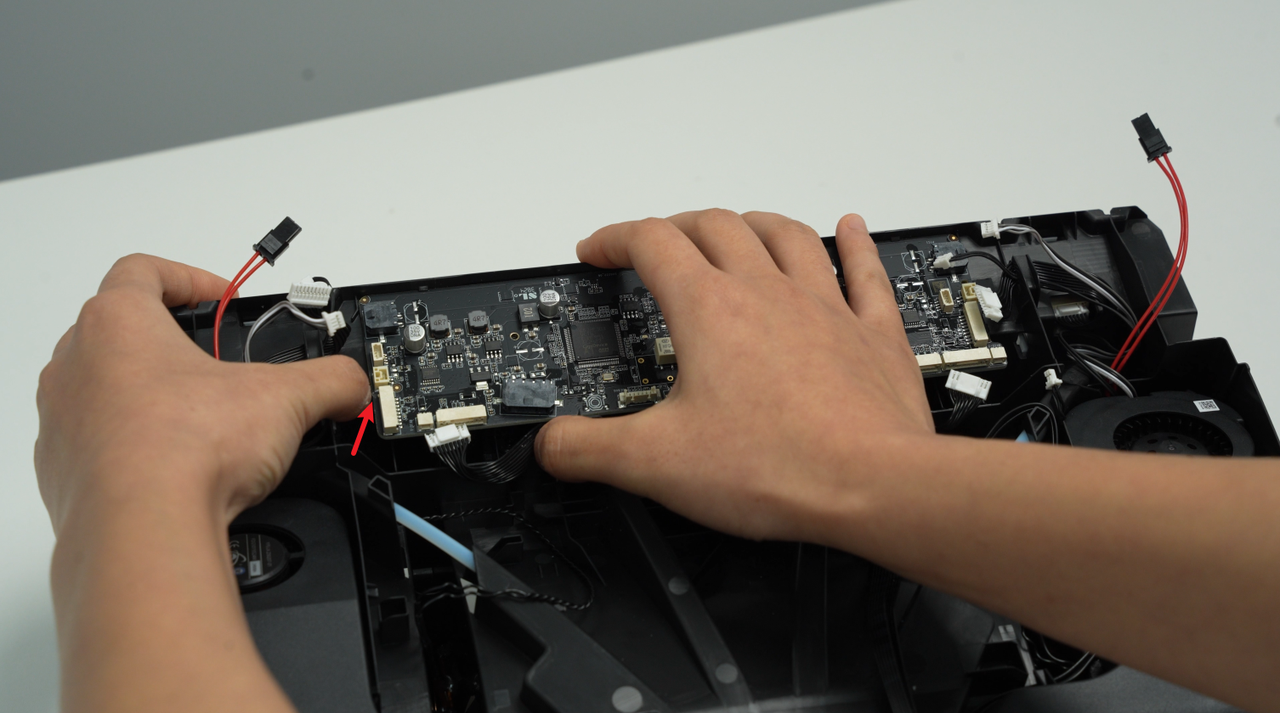
- Install the mainboard on the AMS 2 Pro middle frame. First, insert the mainboard into the 3 clips on the upper edge from bottom to top, then press it down slightly and insert it into the 2 clips on the left and right.
 |
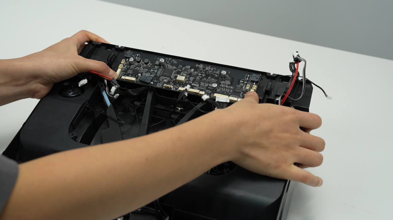 |
Notice: When installing the AMS 2 Pro mainboard, pay attention to checking the plug and do not press the plug on the back of the mainboard.
- Connect 18 cables to the AMS 2 Pro mainboard.
Connect 18 cables according to the marks or photos before disconnection. After confirming that the mainboard is installed and pressed by 5 clips, lock 2 screws.
 |
 |
¶ Install AMS 2 Pro Main Frame Assembly
¶ Step 1 - Check Cable Connections
Please verify that all cables in the cable pack are correctly connected and securely fastened.
¶ Step 2 - Install the Middle Frame Assembly
- Install the AMS middle frame into the AMS bottom cover.
- Connect the power supply cable and signal cable to the AMS 2 Pro power board.

- After the AMS 2 Pro middle frame is installed in place, screw in 2 screws to secure it.
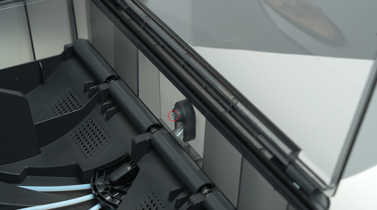
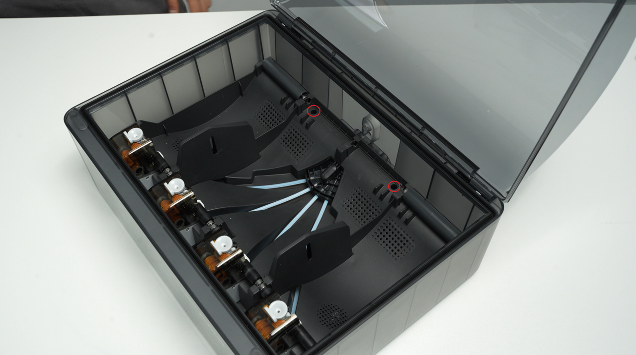
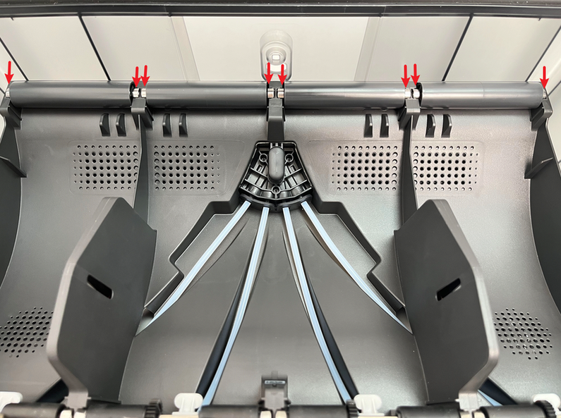
¶ Step 3 - Install Two Driven Support Sleeve Assemblies
Install the 2 middle driven support sleeve assemblies, making sure the bearings at both ends of the 2 driven support sleeves are pressed into place.
 |
 |
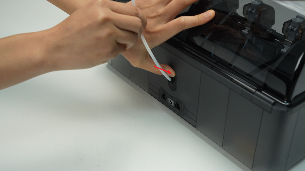
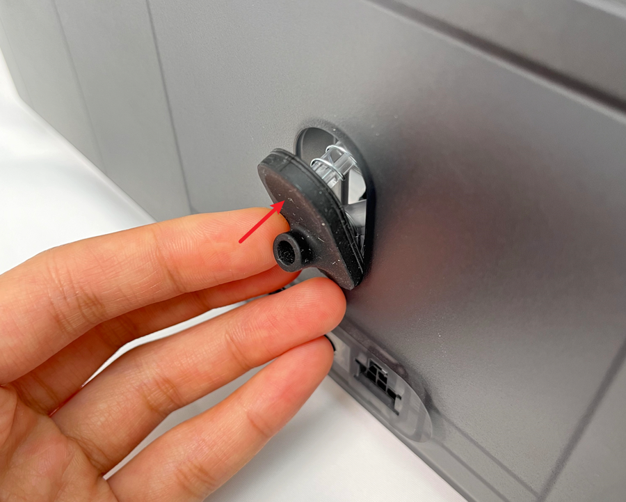
¶ Step 4 - Install the PTFE Tube Release Button
Press the PTFE tube release button back into the housing in the following direction, insert the buckle into the corresponding slot smoothly, and keep the black silicone housing embedded flat.
 |
 |
 |
¶ Step 5 - Connect the PTFE Tube
Check to make sure that the PTFE tube silicone bracket is aligned with the filament hole of the filament hub unit, and push the PTFE tube from the rear of the AMS 2 Pro. After installation, pull the PTFE tube to confirm that the PTFE tube is fixed.
 |
 |
¶ Verify Functionality
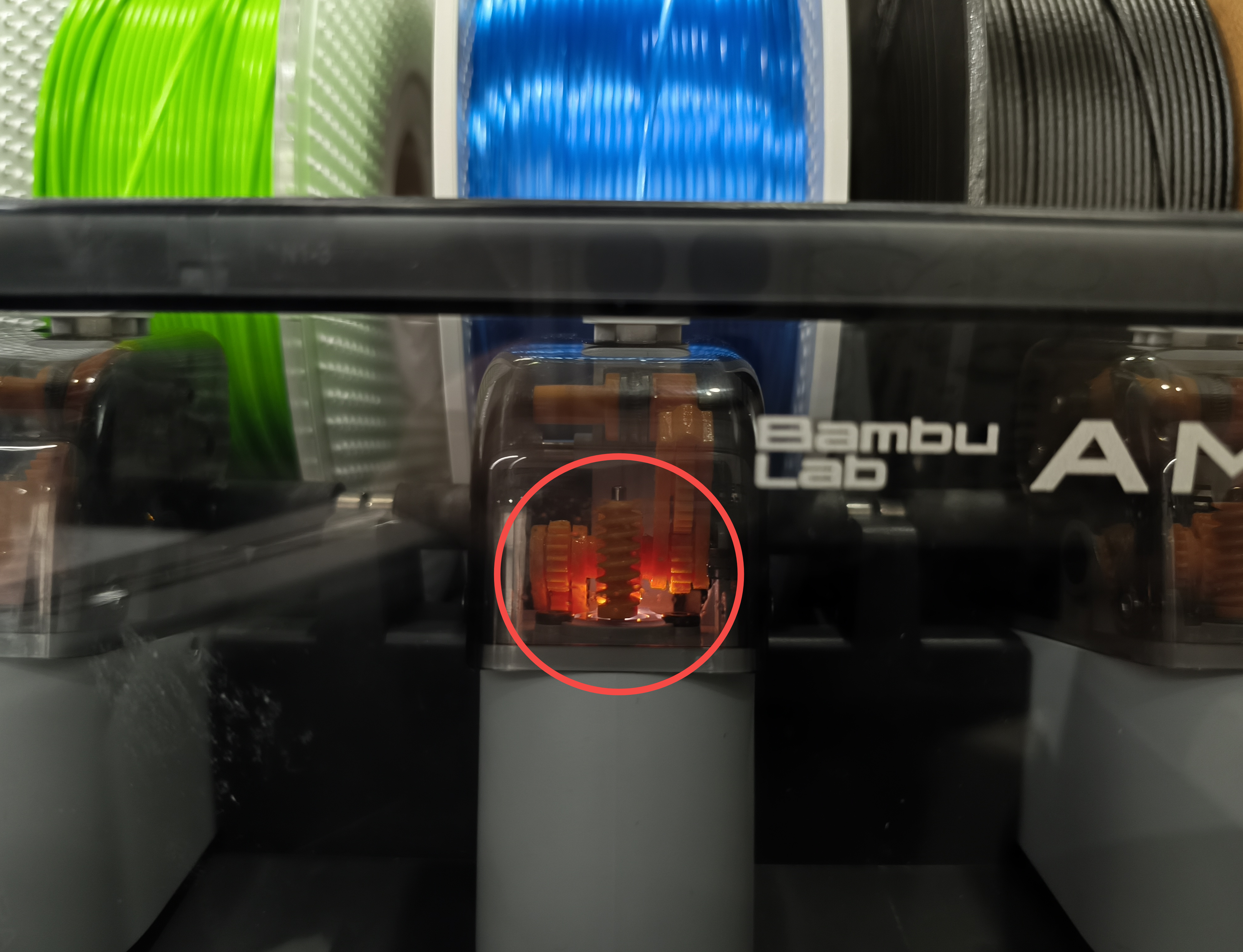
- Connect the AMS 2 Pro to the printer and power on the printer to supply power to the AMS 2 Pro. The indicator light on the first stage feeder should illuminate, indicating normal power supply.
- Load a filament with an RFID chip and ensure that AMS 2 Pro recognizes the filament correctly. Click "Load" to feed the filament, and confirm that AMS 2 Pro successfully delivers the filament to the extruder.
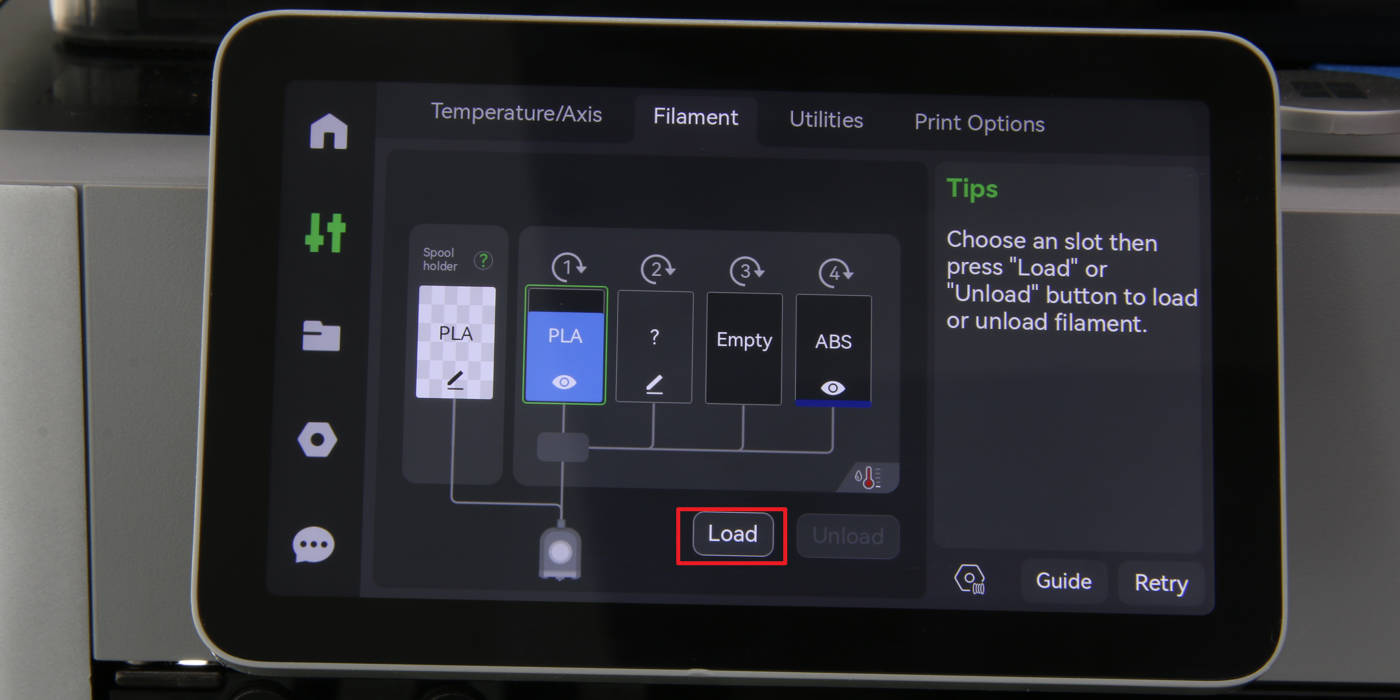
Otherwise, retrace your steps, check the connections, and try again. If problems persist, contact the technical support team for further assistance.
¶ End Notes
We hope the detailed guide provided has been helpful and informative.
To ensure a safe and effective execution, if you have any concerns or questions about the process described in this article, we recommend reaching out to technical support team before initiating the operation. We will do our best to respond promptly and provide the assistance you need. Click here to open a new ticket in our Support Page.