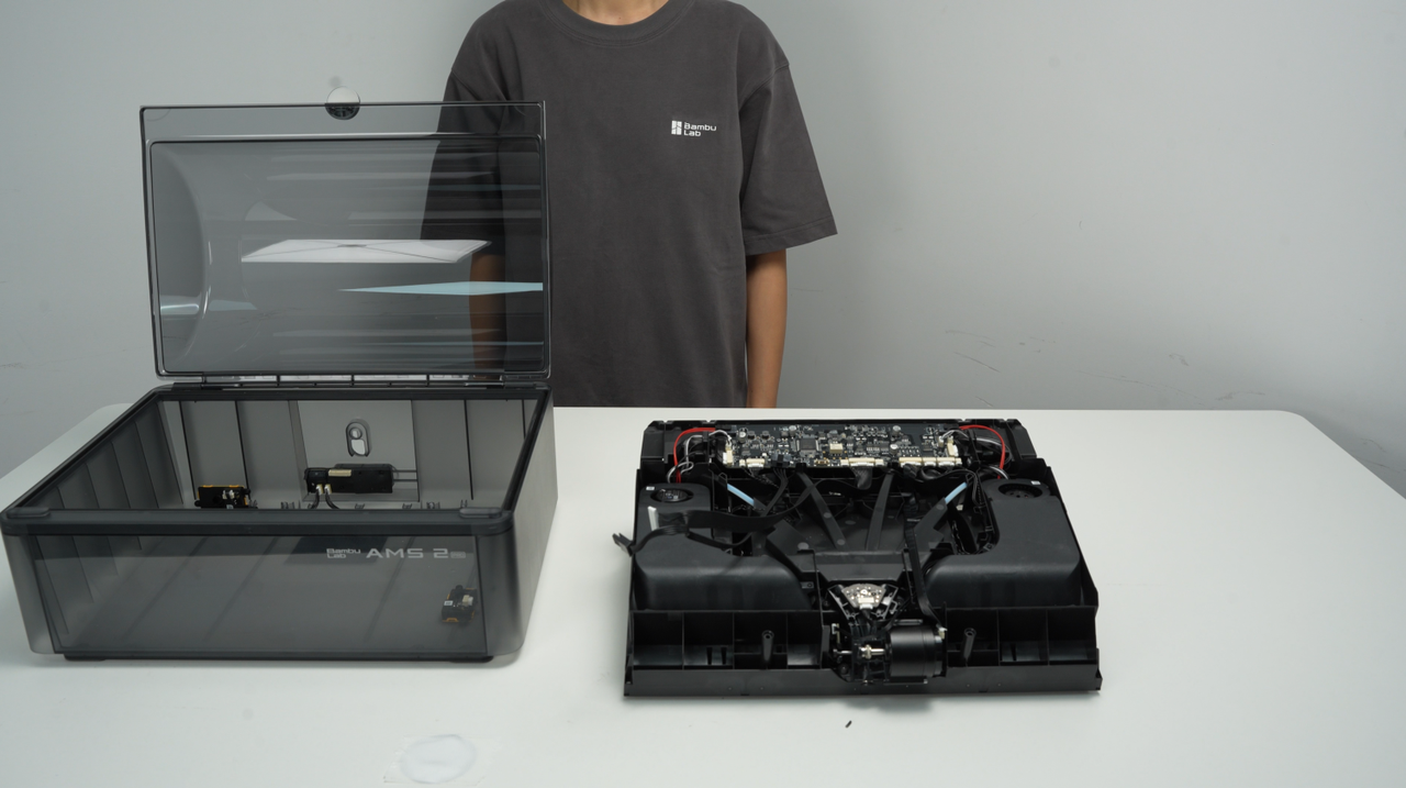
This article provides relevant instructions and precautions for disassembling and assembling the AMS 2 Pro. The disassembly and assembly of replaceable accessories involved in this disassembly process can also be handled by referring to this article.
¶ Parts List
The following are the after-sales single item materials that this guide will involve.
| AMS 2 Pro Top Lid | AMS 2 Pro Feeder Unit | AMS 2 Pro Cable Pack (6-in-1) | |||
|---|---|---|---|---|---|
| AMS 2 Pro Bottom Cover Unit | AMS 2 Pro Mainboard | AMS 2 Pro Drying Unit (slots 1 & 2) | |||
| AMS 2 Pro Driven Support Shaft Assembly | AMS 2 Pro Power Board | AMS 2 Pro Air Intake and Air Vent Unit | |||
| AMS 2 Pro Active Support Shaft Assembly | AMS 2 Pro Internal Filament Hub Unit (including 3520 motor) | AMS 2 Pro PTFE Tube Release Button | |||
| AMS 2 Pro PTFE Tube |
¶ Safety Warning
IMPORTANT!
It's crucial to power off the printer before conducting any maintenance work, including work on the printer's electronics and tool head wires. Performing tasks with the printer on can result in a short circuit, leading to electronic damage and safety hazards.
During maintenance or troubleshooting, you may need to disassemble parts, including the hotend. This exposes wires and electrical components that could short circuit if they contact each other, other metal, or electronic components while the printer is still on. This can result in damage to the printer's electronics and additional issues.
Therefore, it's crucial to turn off the printer and disconnect it from the power source before conducting any maintenance. This prevents short circuits or damage to the printer's electronics, ensuring safe and effective maintenance. For any concerns or questions about following this guide, we recommend submitting a technical ticket regarding your issue and we will do our best to respond promptly and provide the assistance you need.
¶ Assemblies List
The assemblies require additional disassembly.
| AMS 2 Pro Feeder Unit | AMS 2 Pro Internal Filament Hub Unit (including 3520 motor) |
|---|
¶ Tools and materials needed
-
H2.0 Allen key
-
H1.5 Allen key
-
60 minutes
¶ Screw list
A:BT3x8
B:BT2x5
C:BTG2x11x4
D:BT2x8
E:BT2x4
F:BT2x6
¶ Video Guide
¶ Disassembly Guide
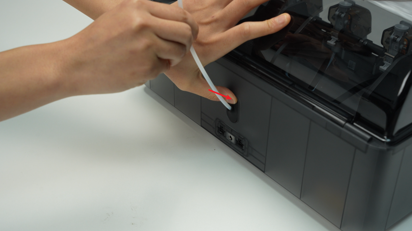
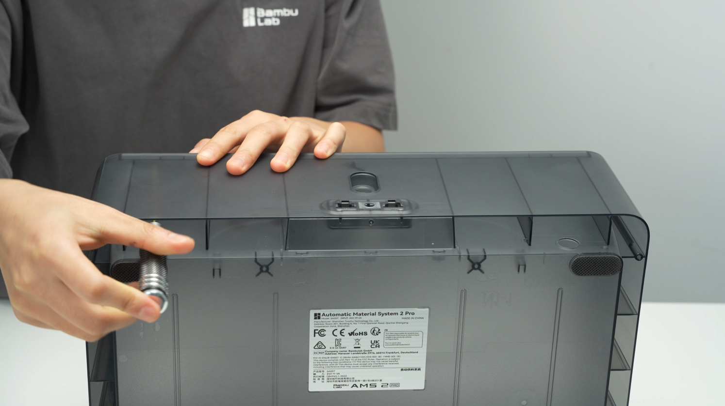
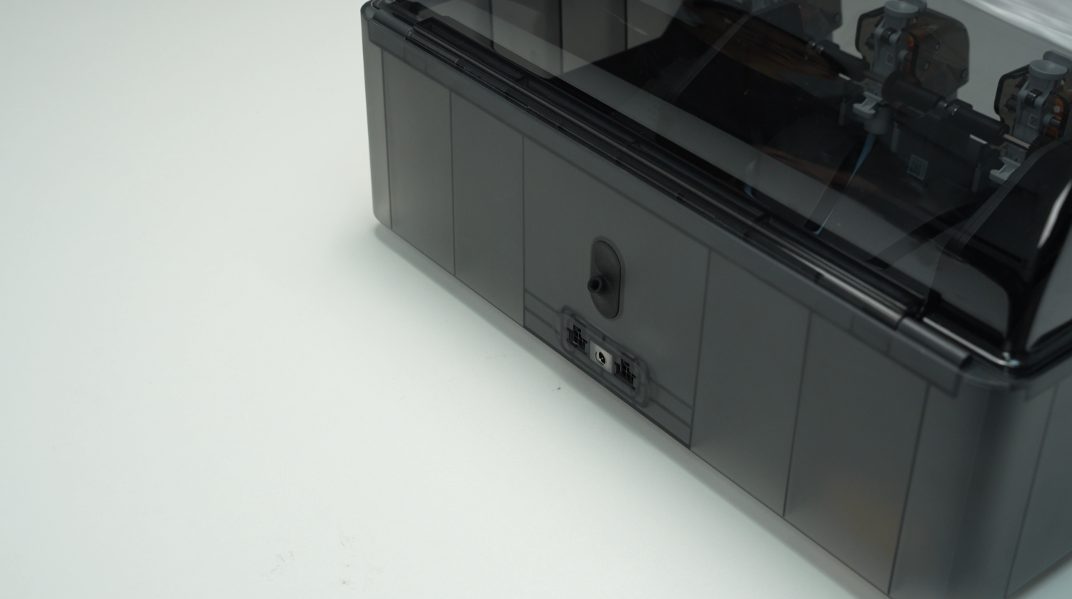
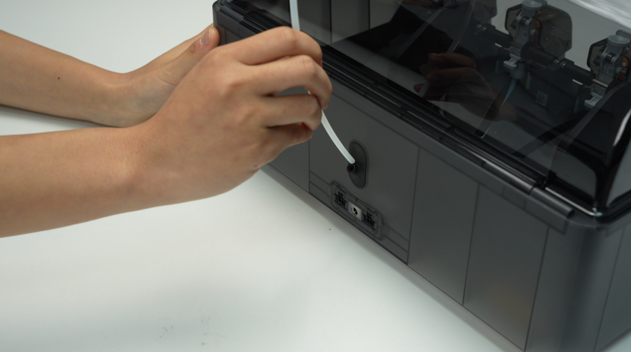
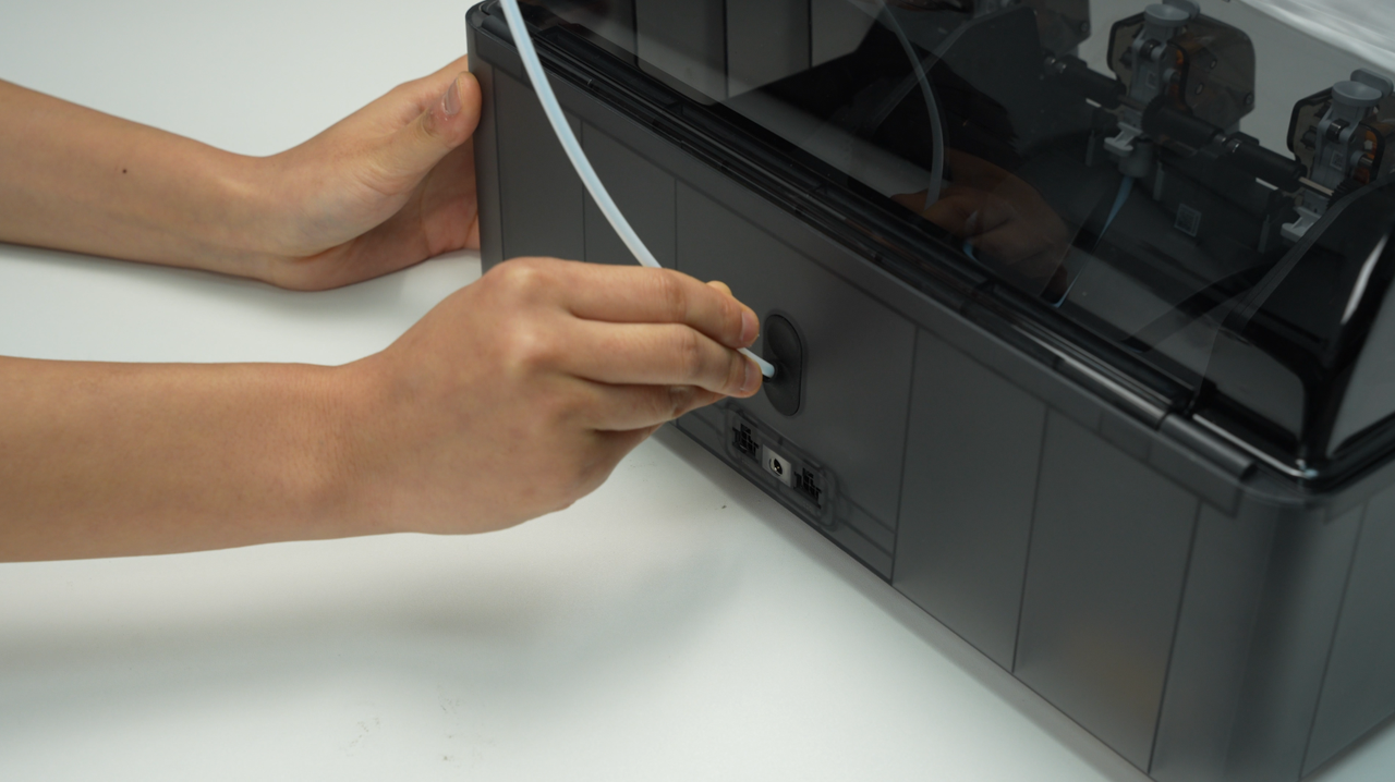
¶ Step 1 - Remove the PTFE tube on the back of the AMS
Press the PTFE tube release button from the back of the AMS to unlock the fitting, then pull the PTFE tube out from the back of the AMS.
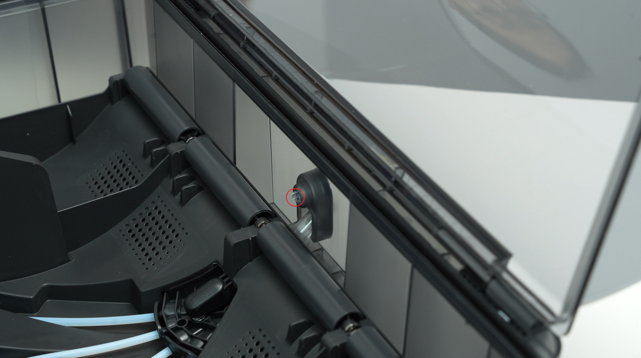
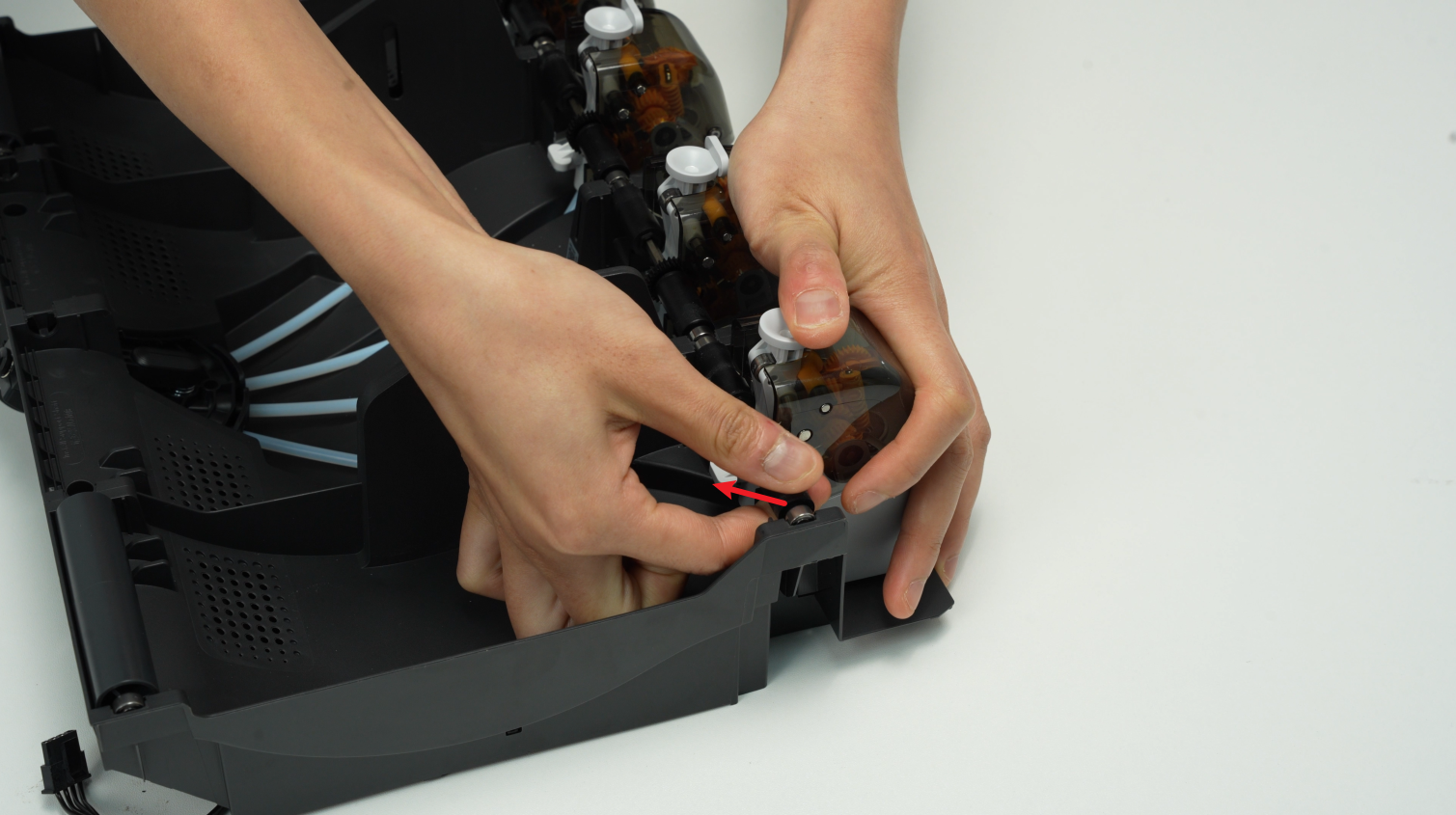
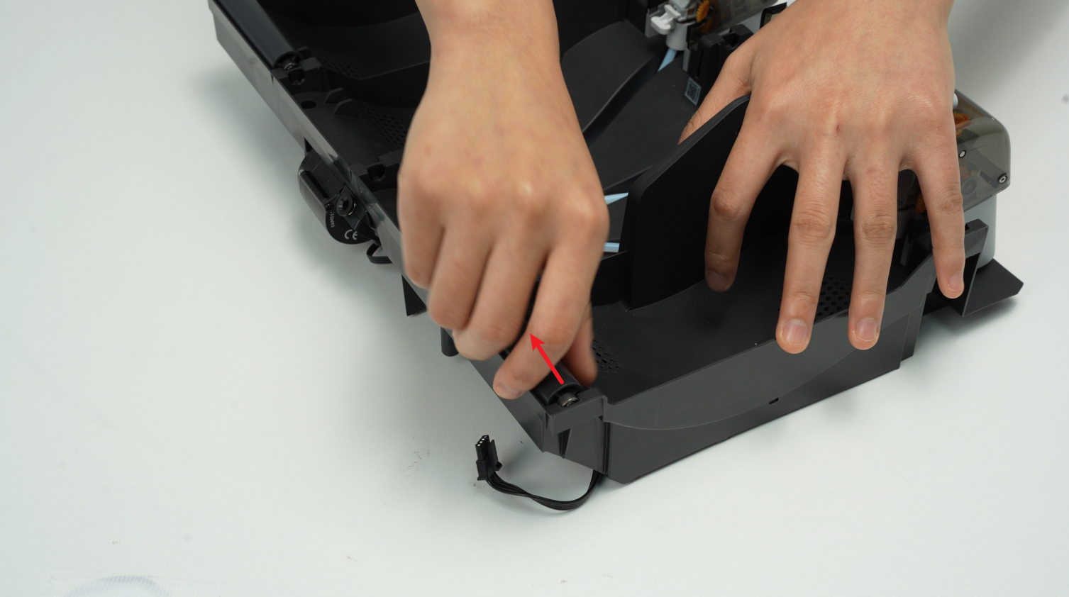
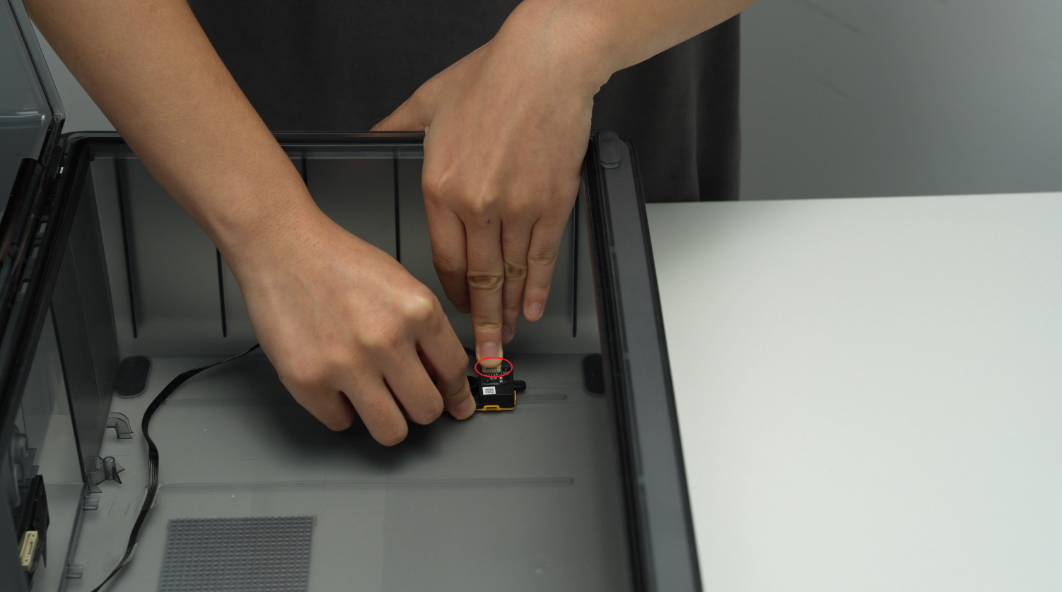
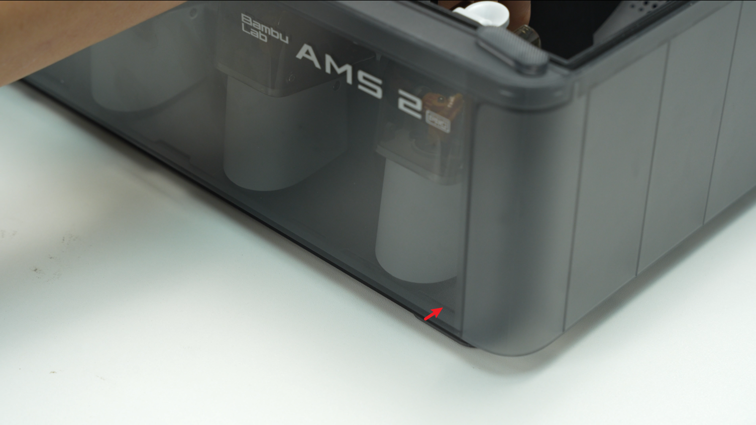
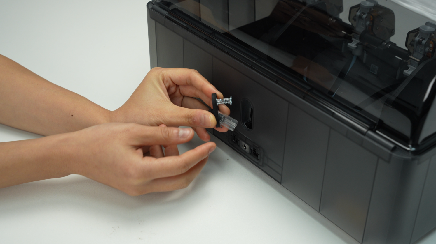
¶ Step 2 - Pull out the PTFE tube release button
Pinch the clip from the inside of the lower cover to automatically pop open the PTFE tube release button, and then pull out the PTFE tube release button from the back of the AMS.
 |
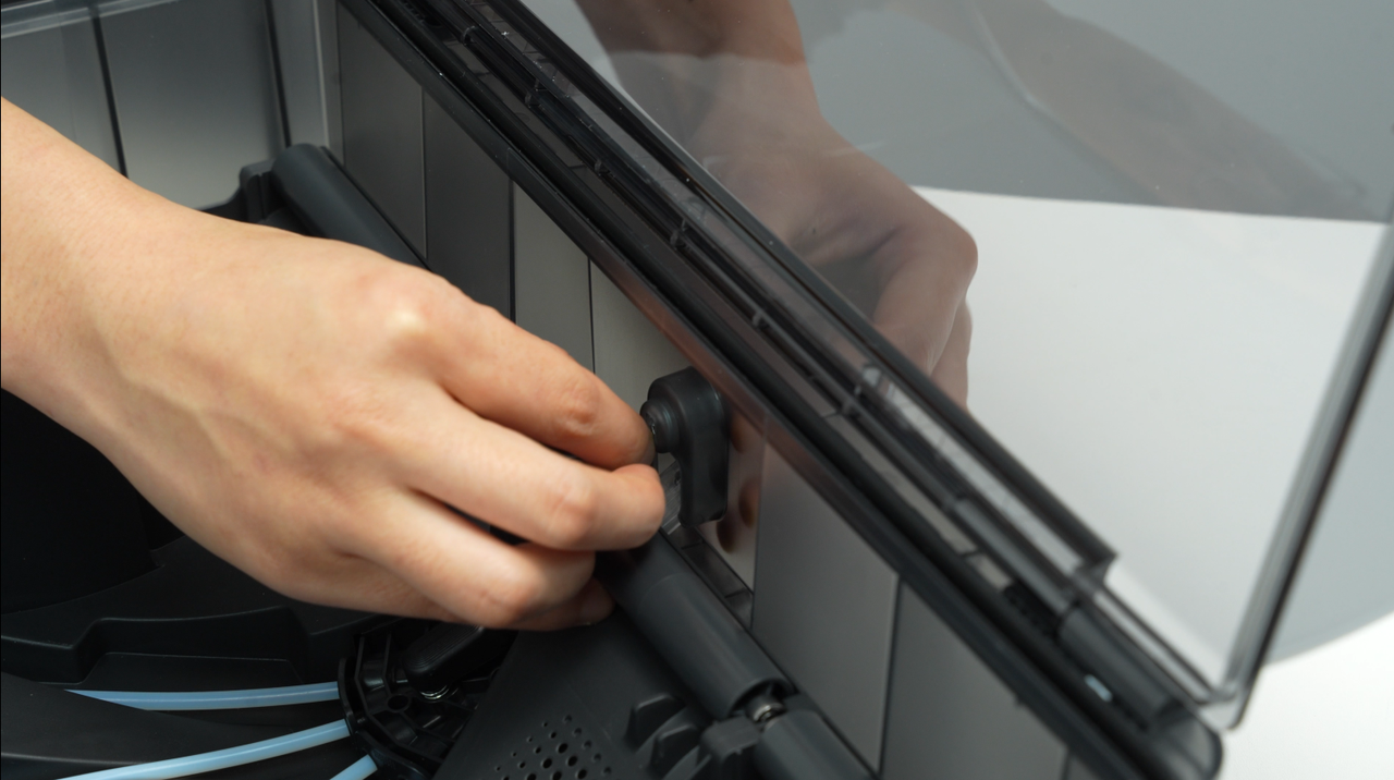 |
When squeezing the buckle, use your other hand to hold the PTFE tube from the back of the AMS to release the switch to prevent the spring from being ejected and lost.
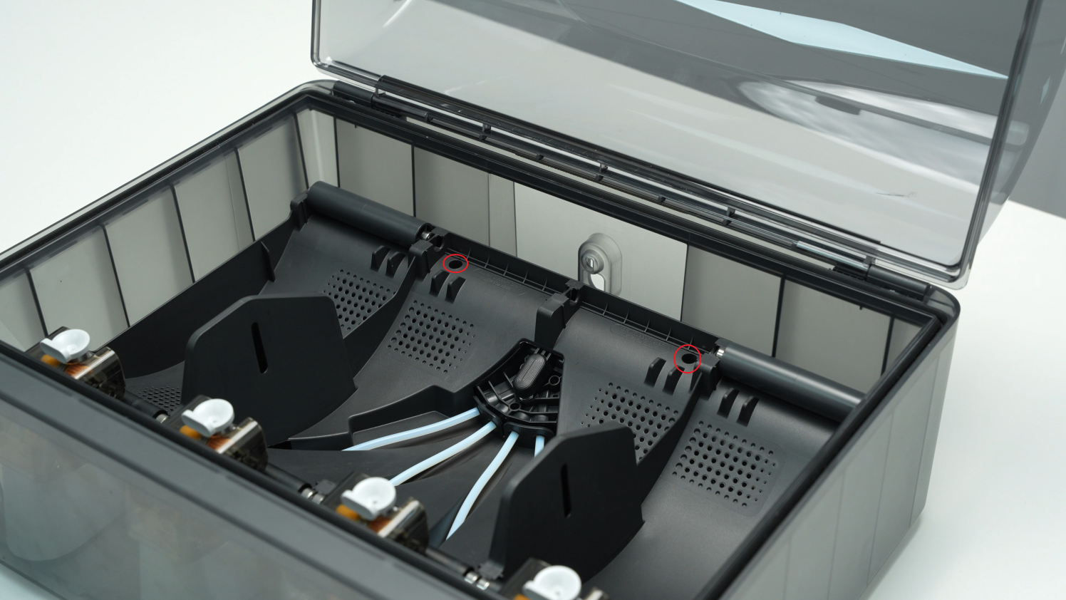
¶ Step 3 - Remove the AMS main frame assembly
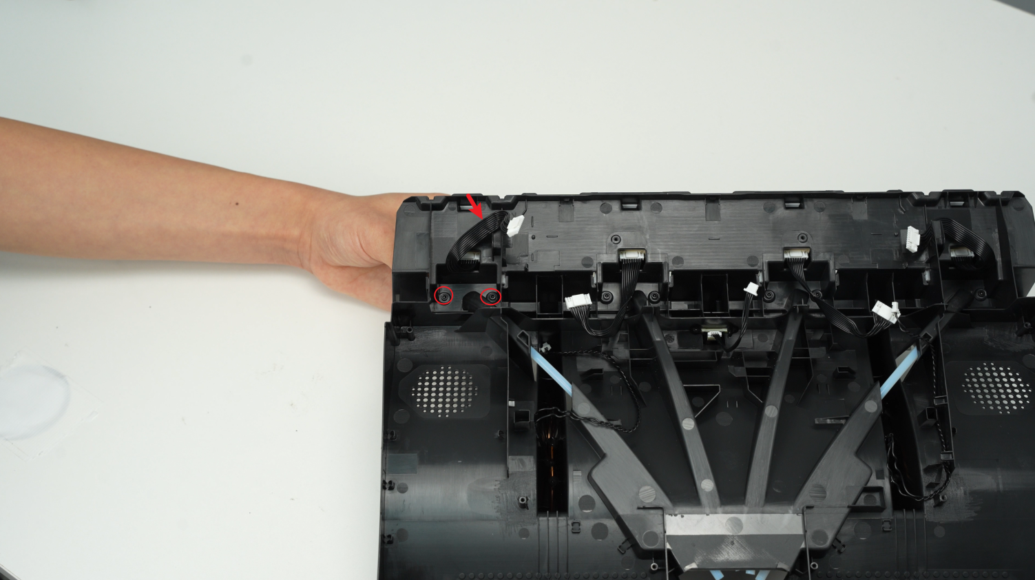
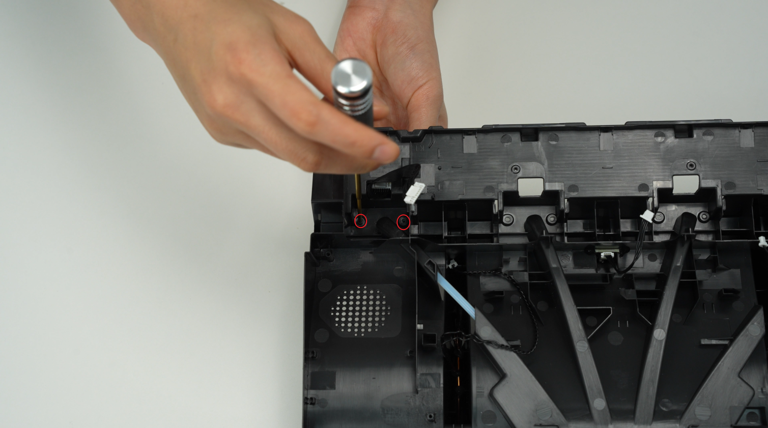
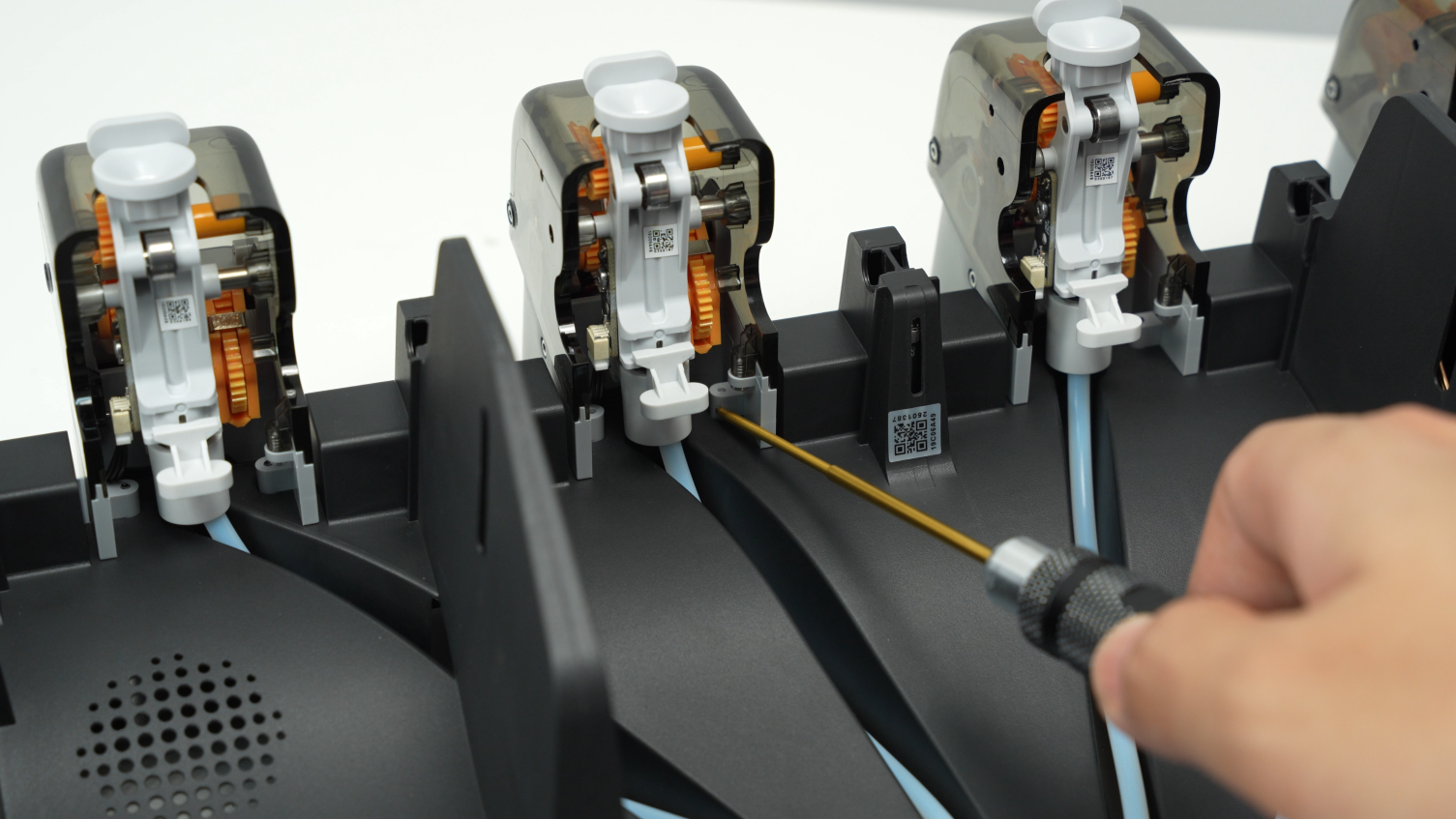
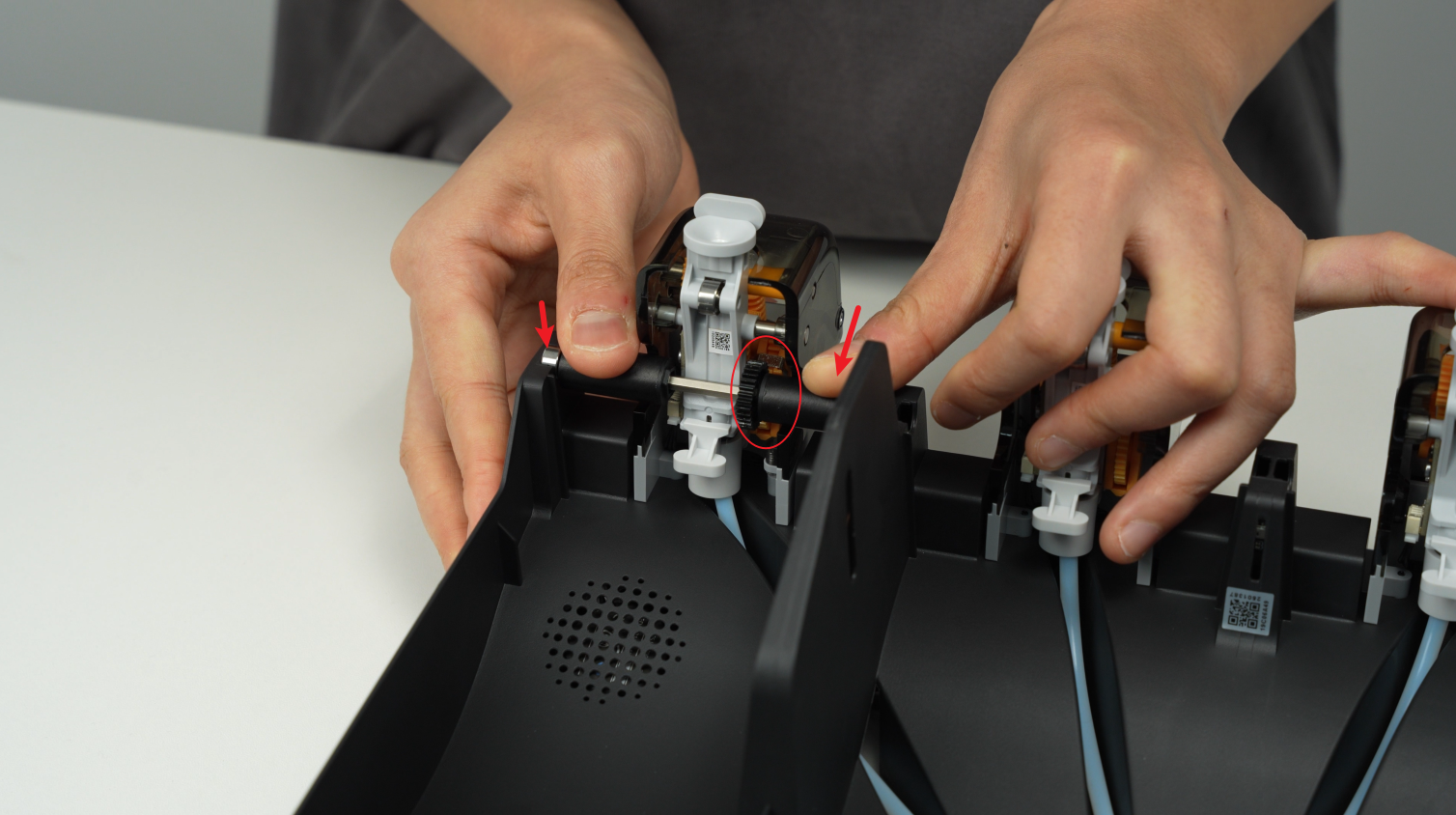
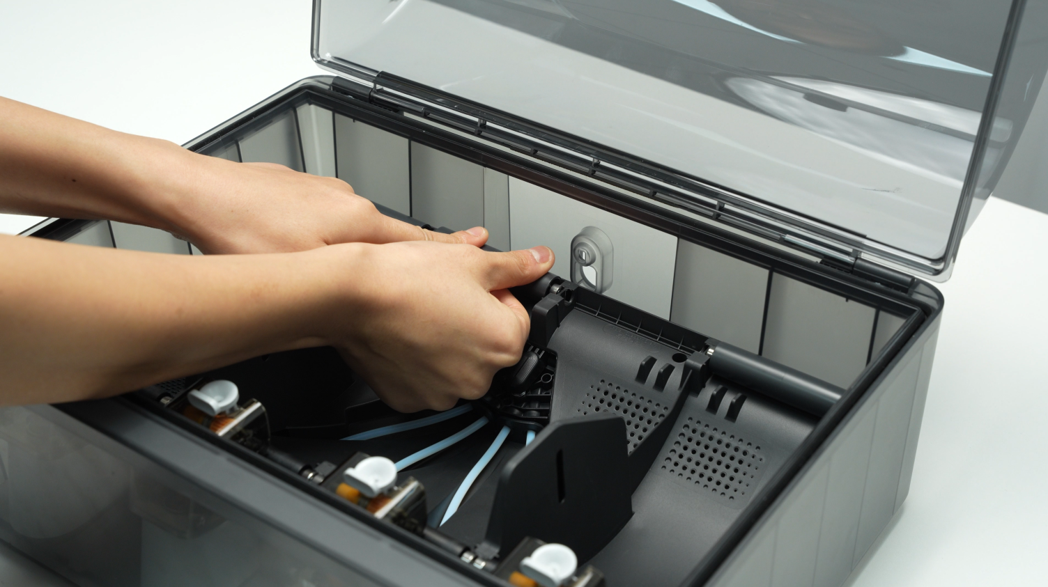
Remove the driven support sleeve assembly of the two middle slots to expose the two screw holes. When removing the bearing sleeve, be careful with the bearings at both ends to avoid losing them.
 |
 |
Remove the two screws A that secure the AMS main frame.
 |
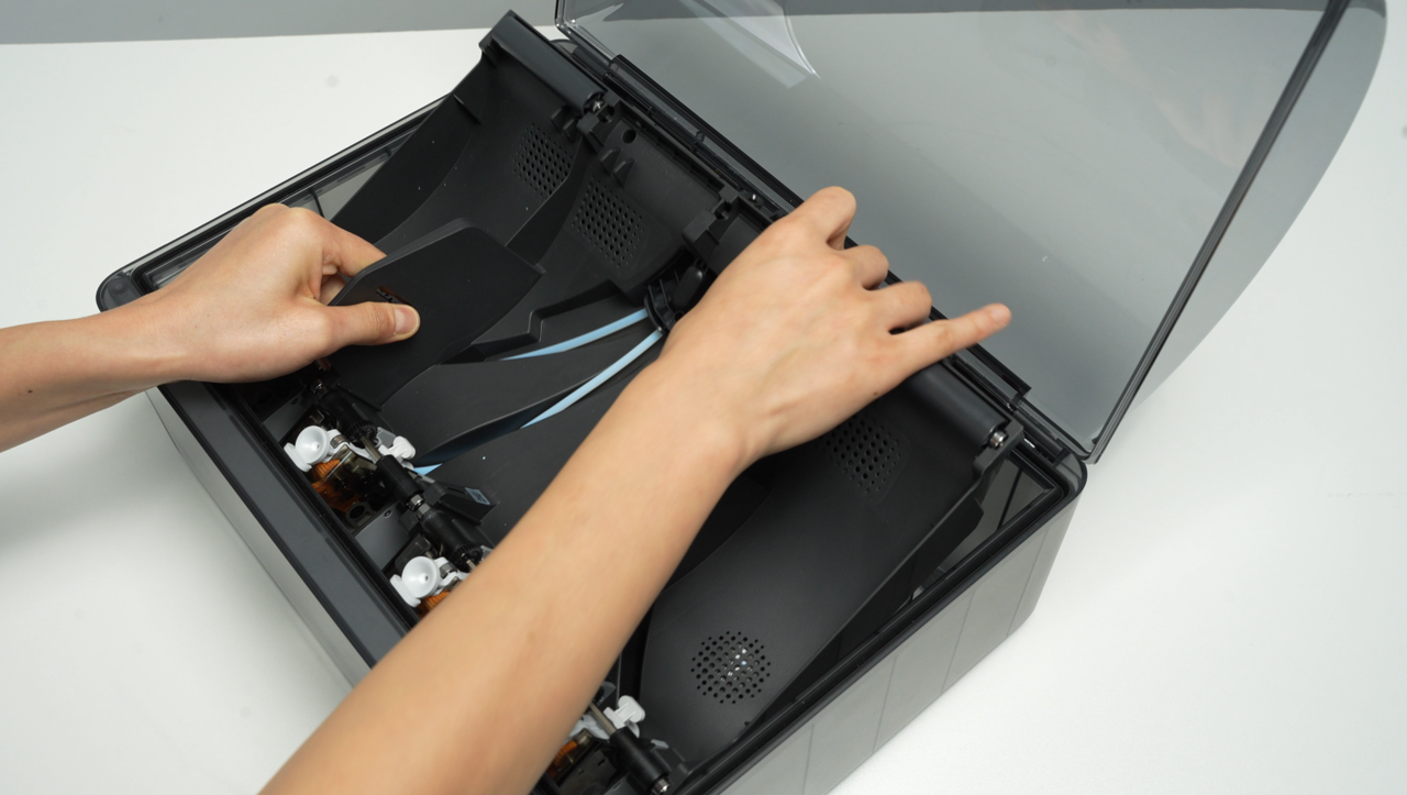 |
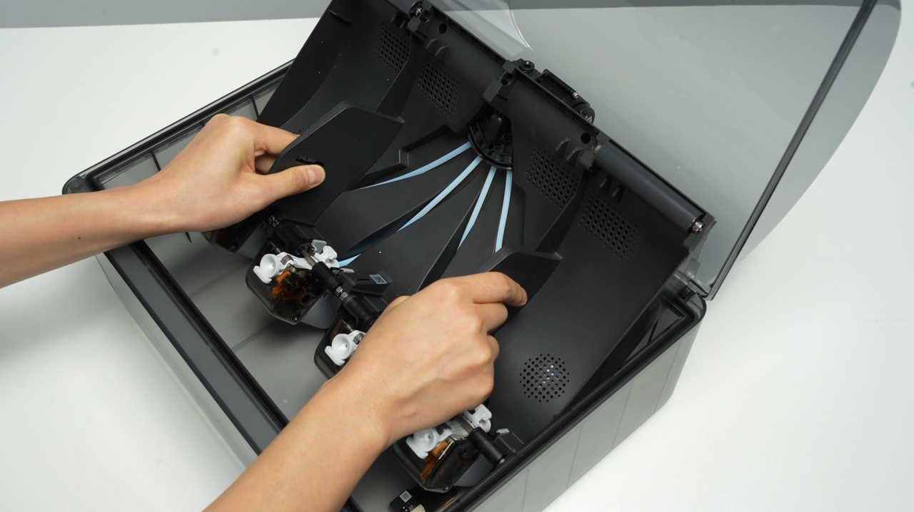
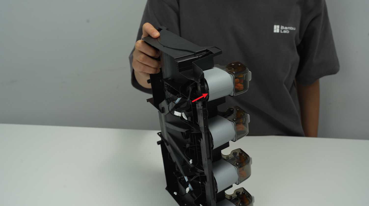
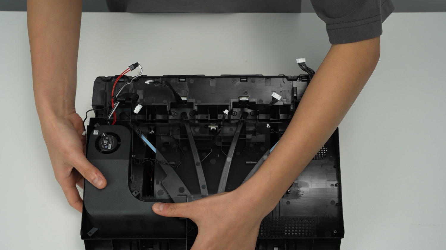
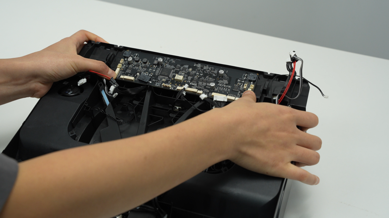
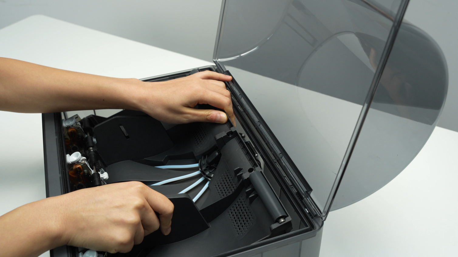
Lift the rear part of the main frame completely and place it vertically on the lower cover of the AMS. Note that there are cables connected, so do not operate violently. When lifting, it is recommended to lift the front part of the main frame first, and then push it forward to make room for the rear part of the frame.
When placing the AMS main frame vertically, avoid the electronic components of the vent to prevent them from being crushed.
 |
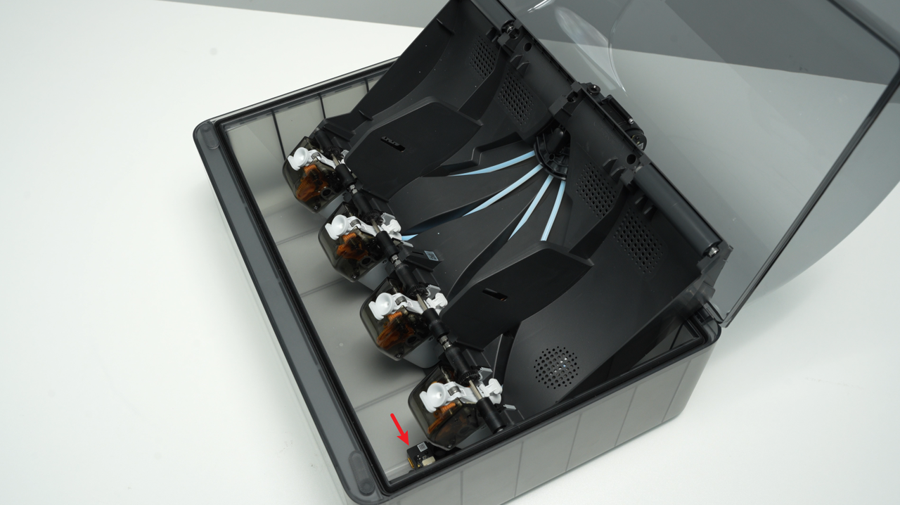 |
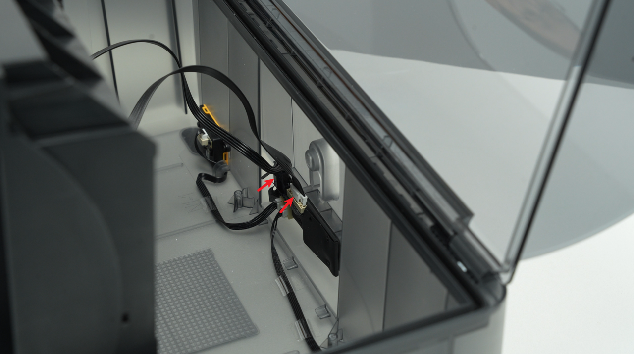
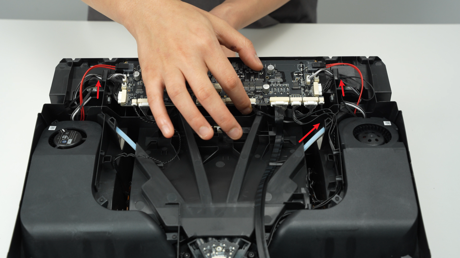
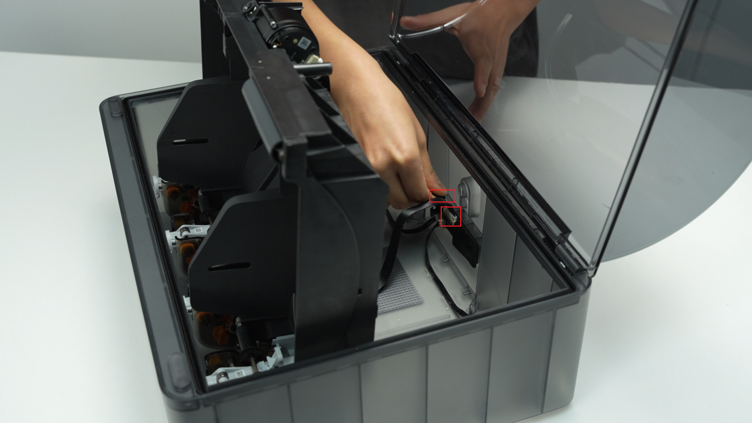
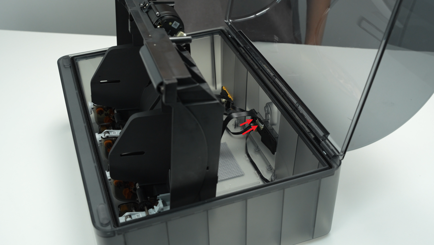
Unlock the plug buckle, unplug the signal cable and power cable on the AMS power board, and lift out the AMS main frame assembly as a whole.
 |
 |
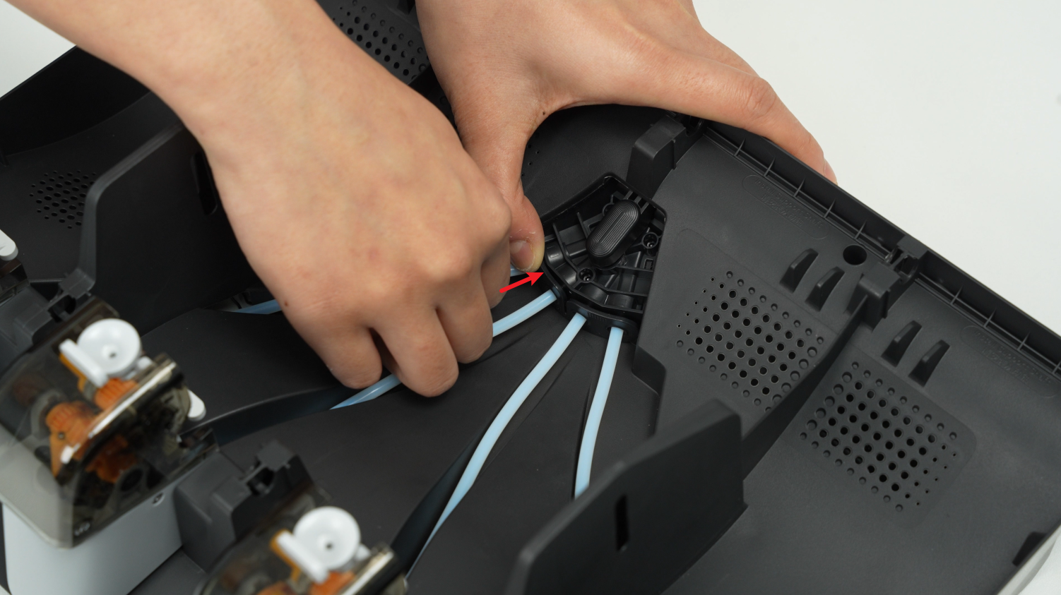
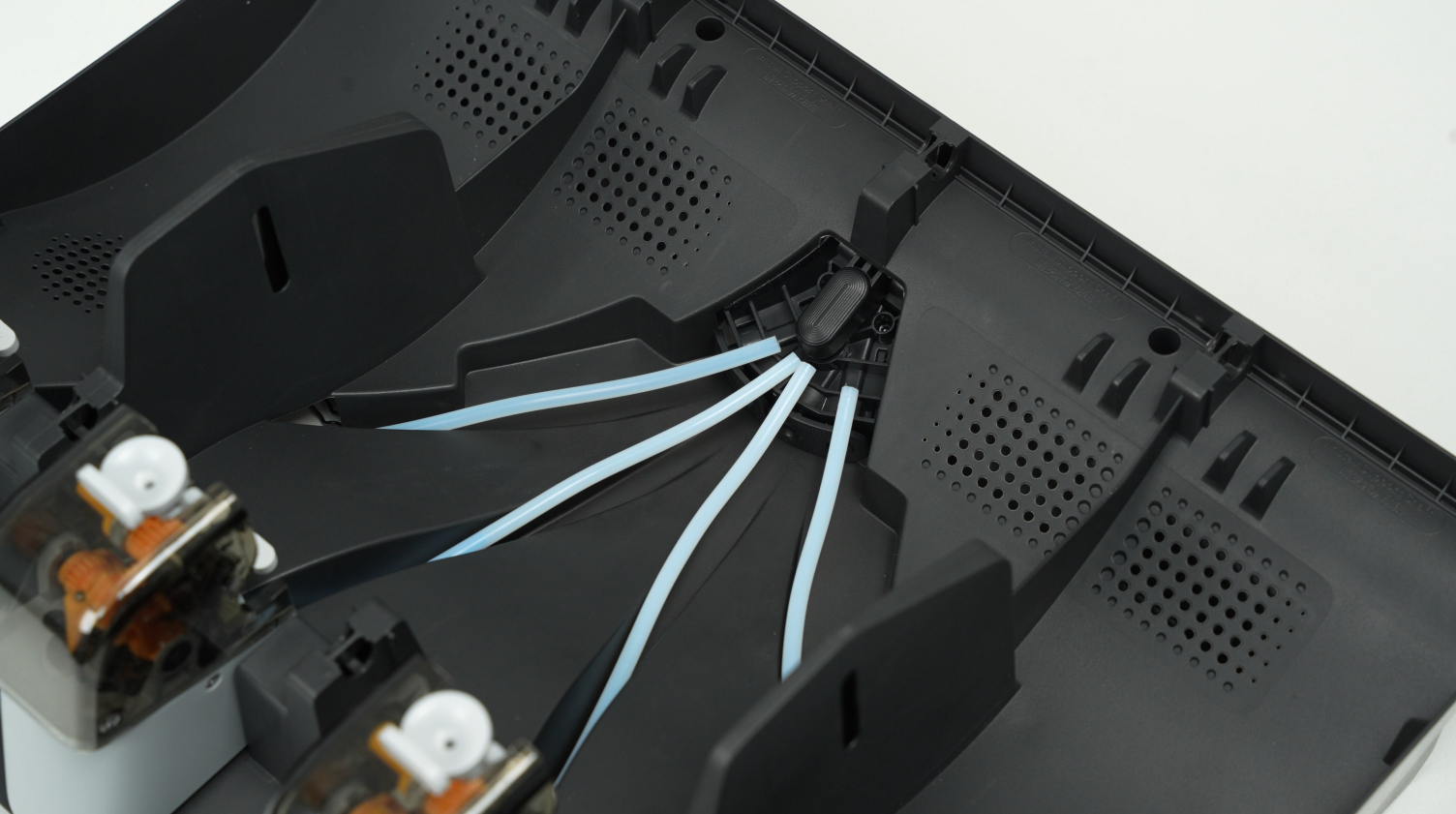
¶ Step 4 - Remove the support sleeve assemblies and unlock the PTFE tubes
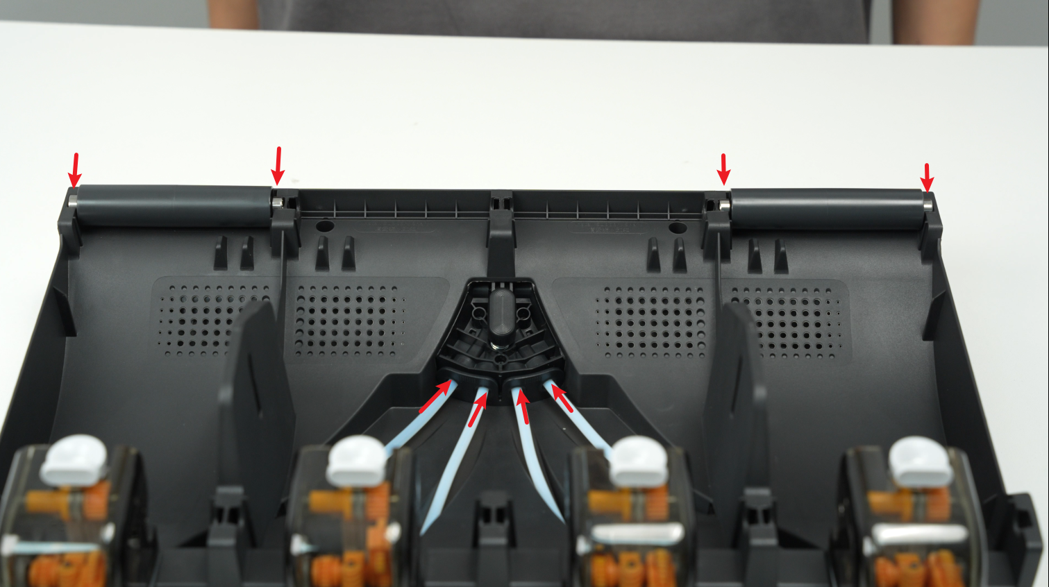
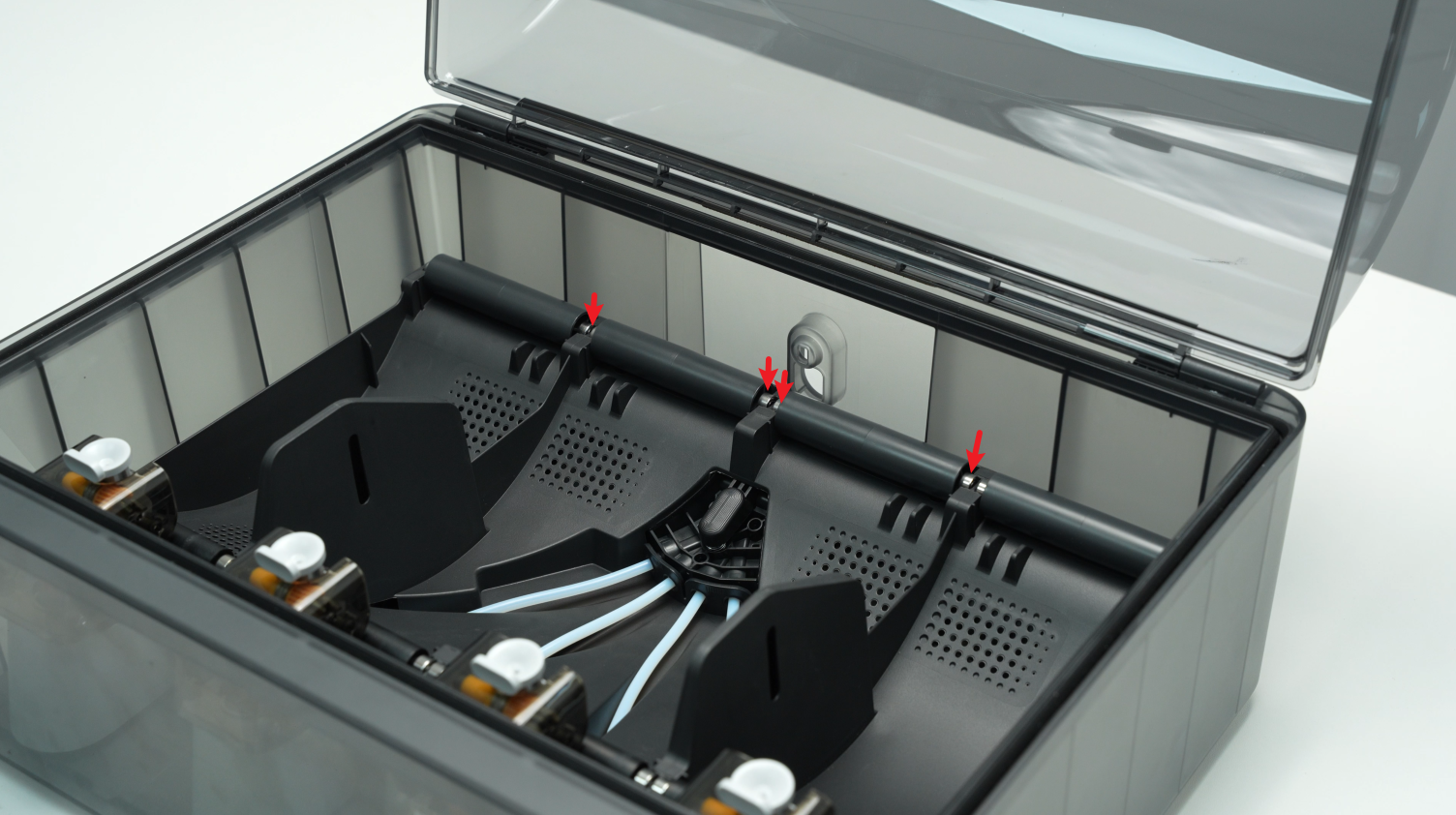
Remove the 4 AMS middle frame active support sleeve assemblies and the remaining 2 driven support sleeve assemblies. Unlock the filament hub bracket and disconnect the 4 PTFE tubes from the filament hub.
 |
 |
 |
 |
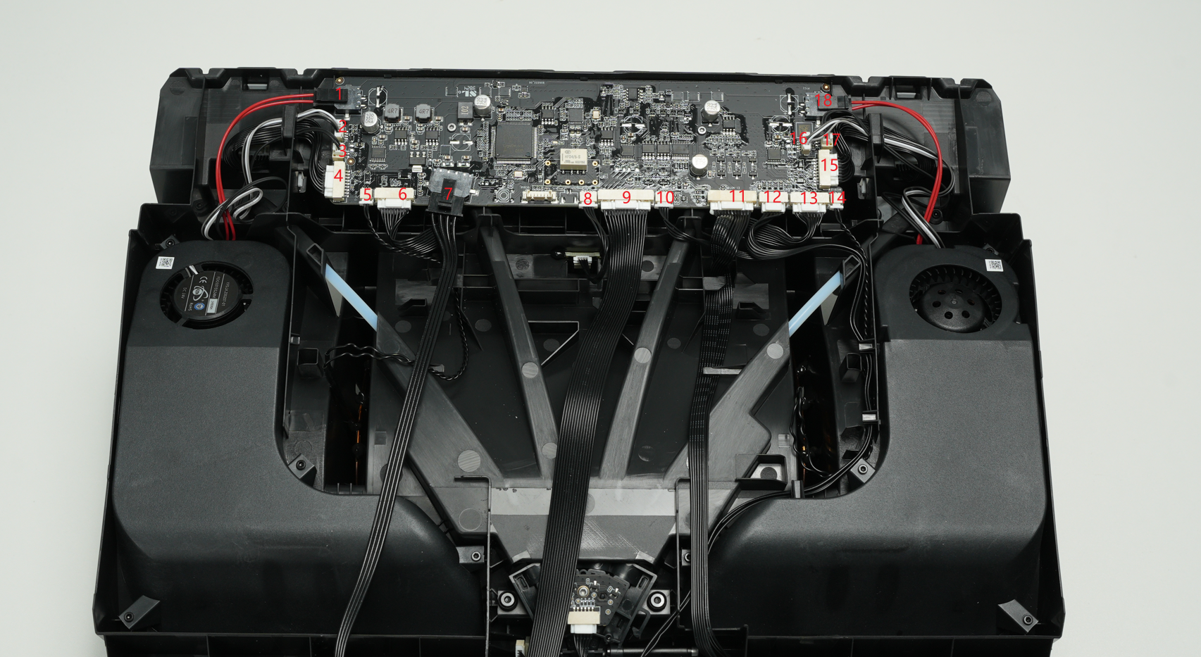
¶ Step 5 - Disconnect 18 cables from the AMS mainboard
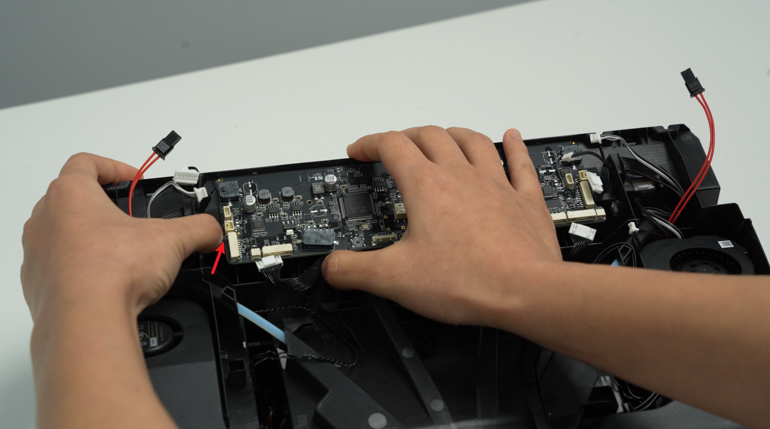
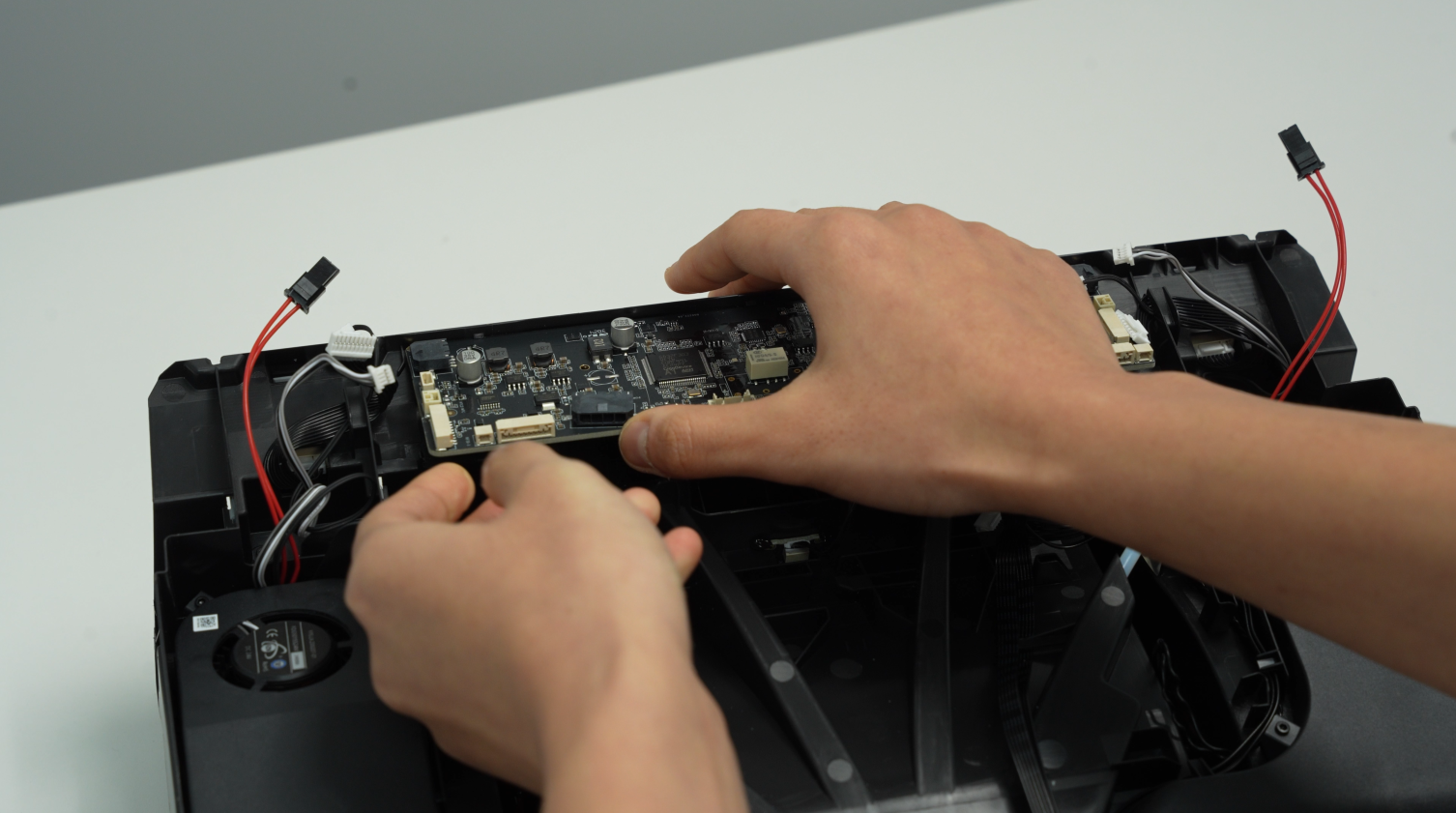
¶ Step 6 - Remove the mainboard
The AMS mainboard is secured by 2 screws B and 5 clips.
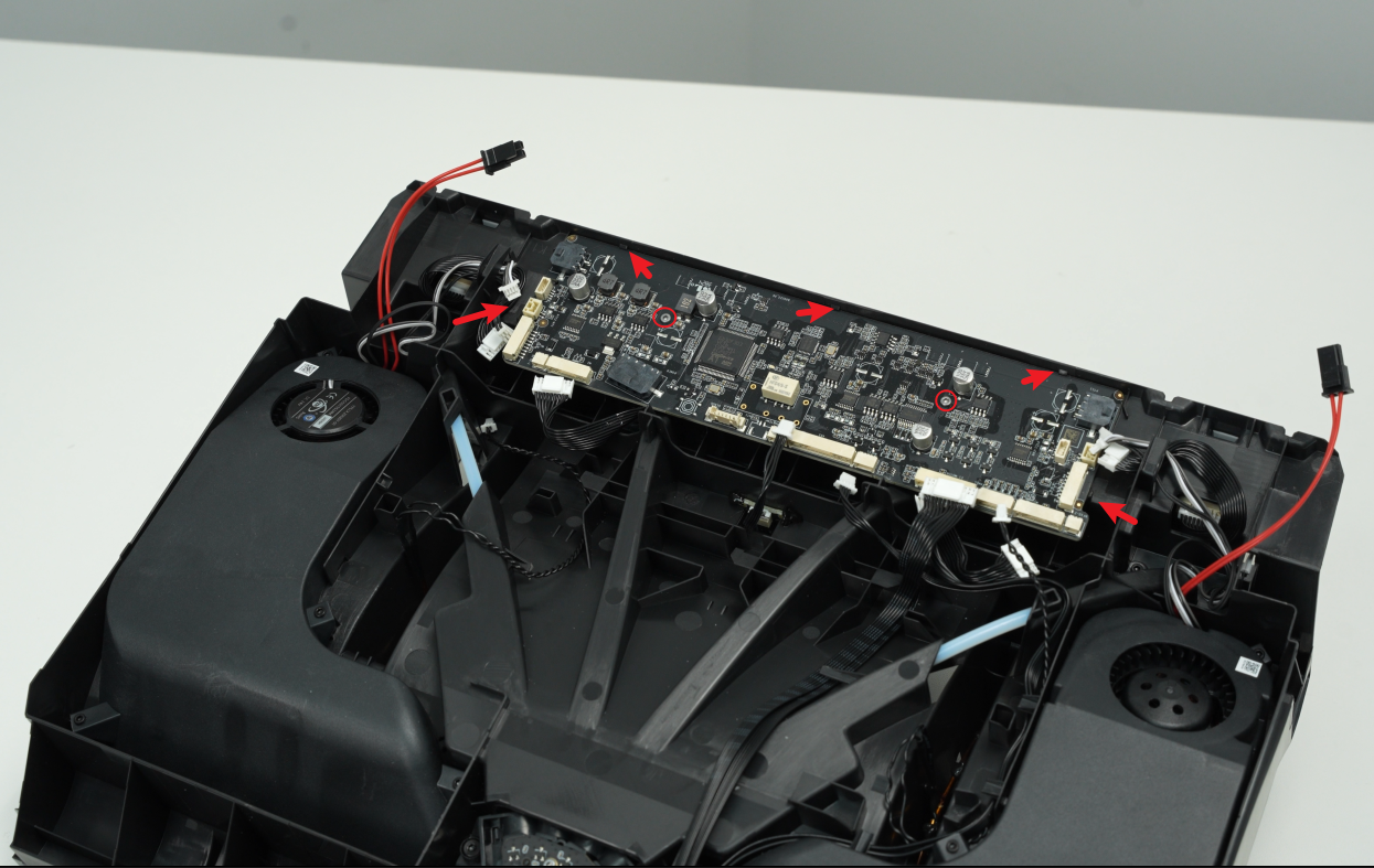
After removing the 2 screws, gently pull the leftmost clip outward, lift the AMS mainboard from the bottom, and remove the AMS mainboard.
 |
 |
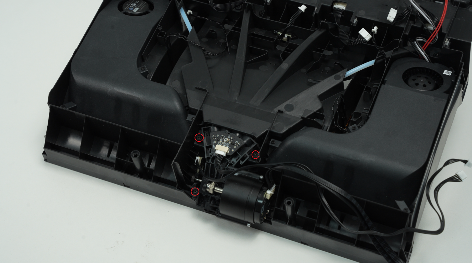
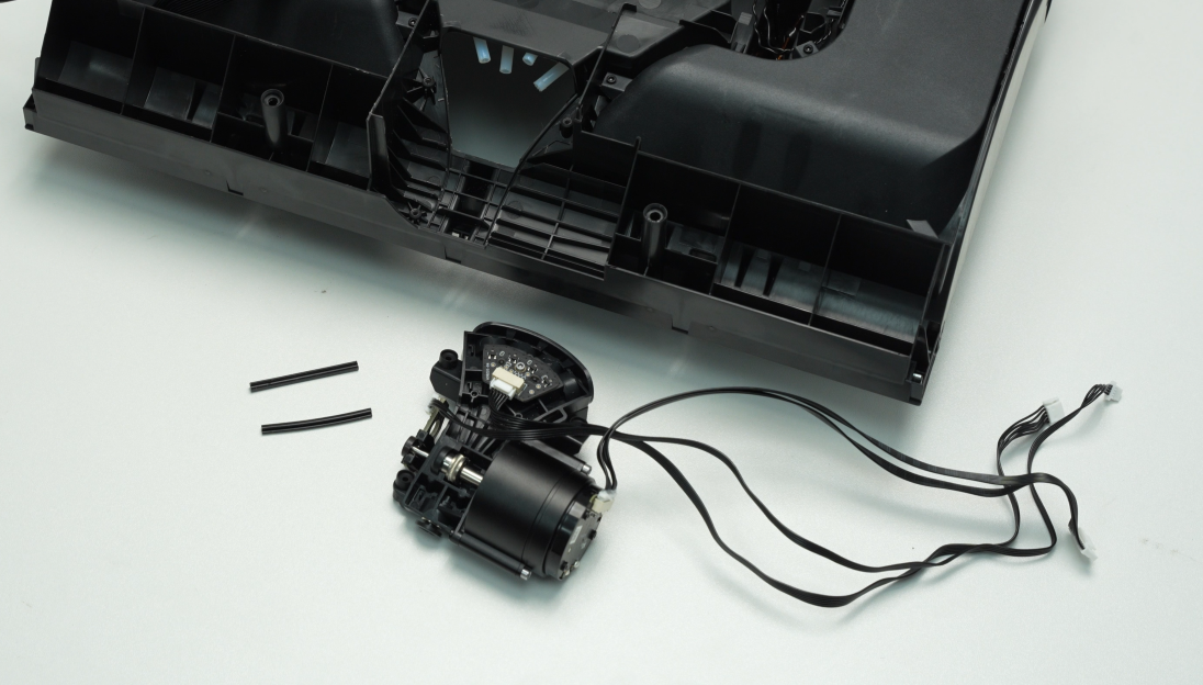
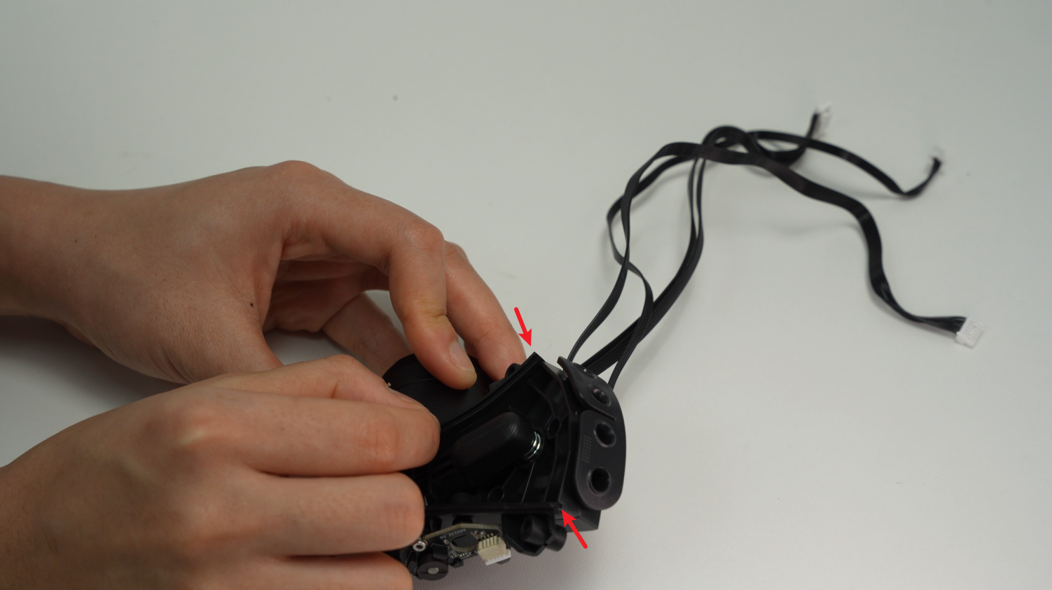
¶ Step 7 - Remove the filament hub
Release the 3 cables of the filament hub from the clips, unscrew the 3 screws C, remove the filament hub, and carefully store the shock-proof silicone strip of the filament hub to avoid losing it.
 |
 |
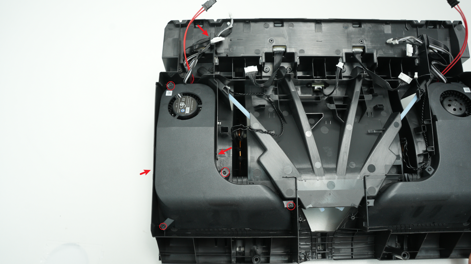
¶ Step 8 - Remove the left and right drying units
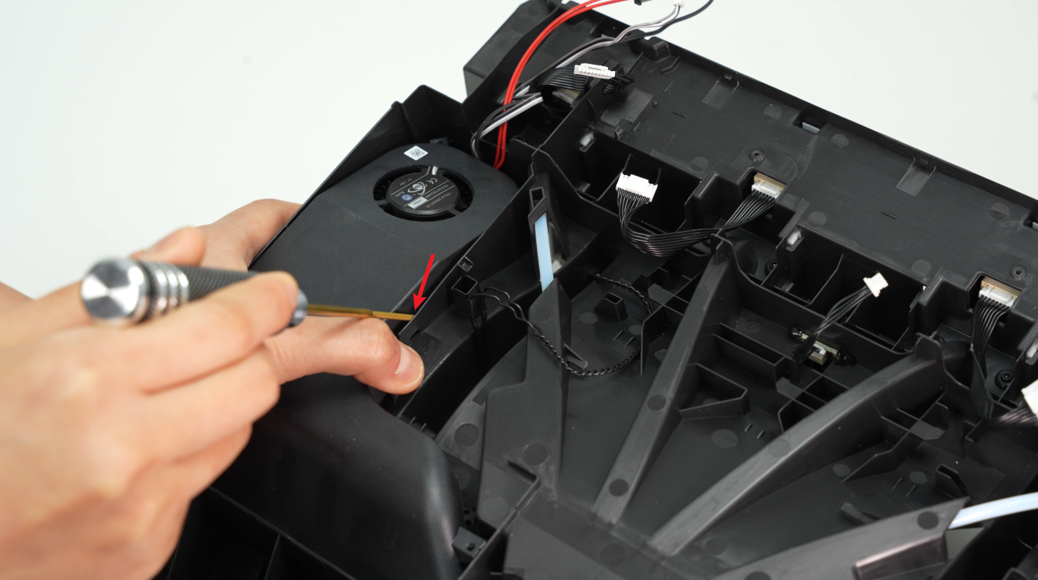
One air duct is fixed by 4 screws and 2 clips. Pull out the cables from the cable channel, unscrew 4 screws D, pry open 2 clips, and remove the drying unit.
 |
 |
After removing the 4 screws D, you need to use an H1.5 Allen key to pry out the plastic frame near the buckle to unlock the two air duct clips. It is recommended to pry open the clip near the RFID coil first. After prying it open, lift the drying unit with your hands, pry up the other clip, and then remove the drying unit.
 |
 |
¶ Step 9 - Remove 4 feeder units
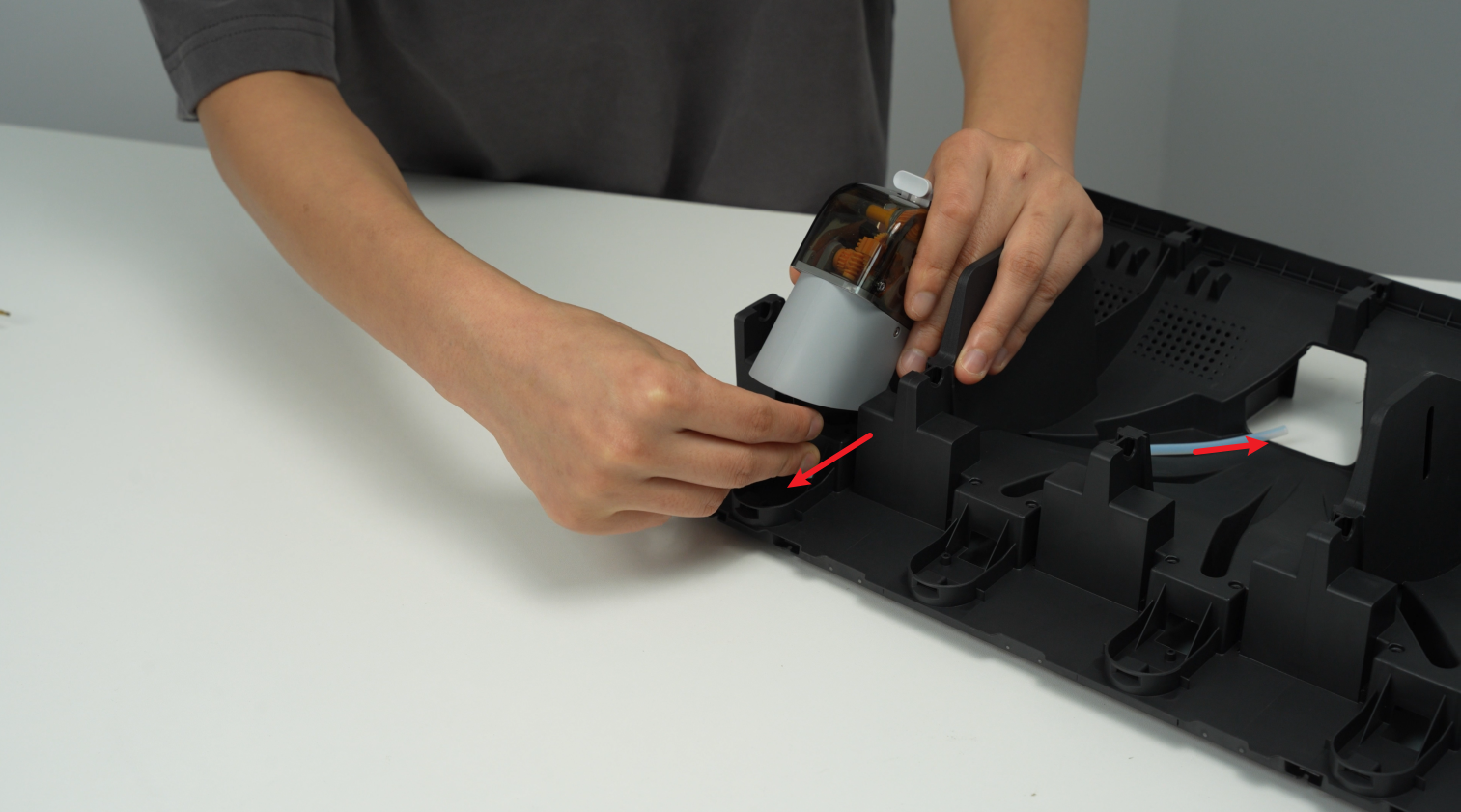
One feeder unit is fixed by 2 screws and 1 clip. Pull out the cables from the cable channel, remove the 2 screws D, shake the feeder unit forward, release the clip in front, and remove it. Remove the other 3 feeder units in the same way.
 |
 |
 |
 |
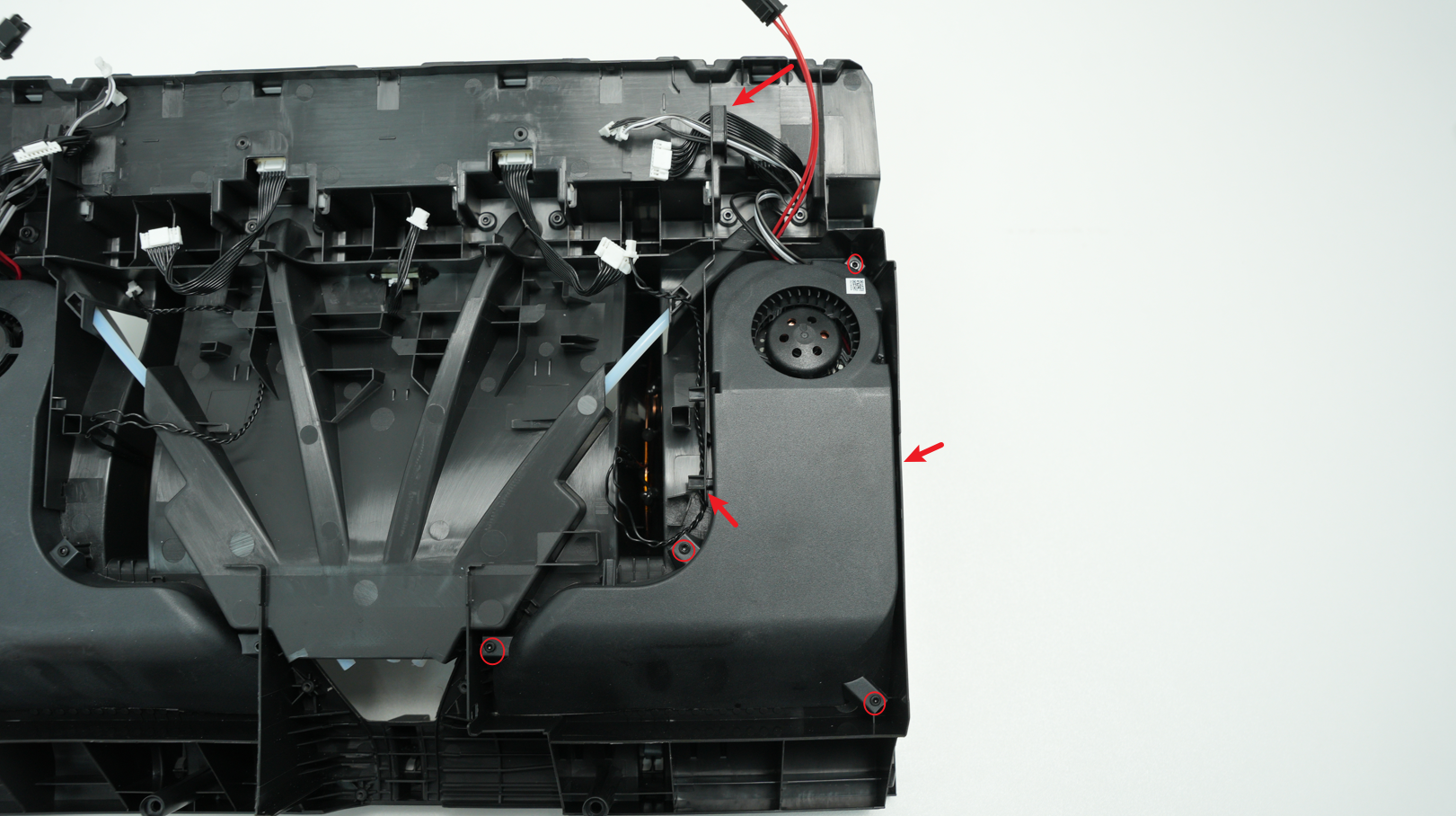
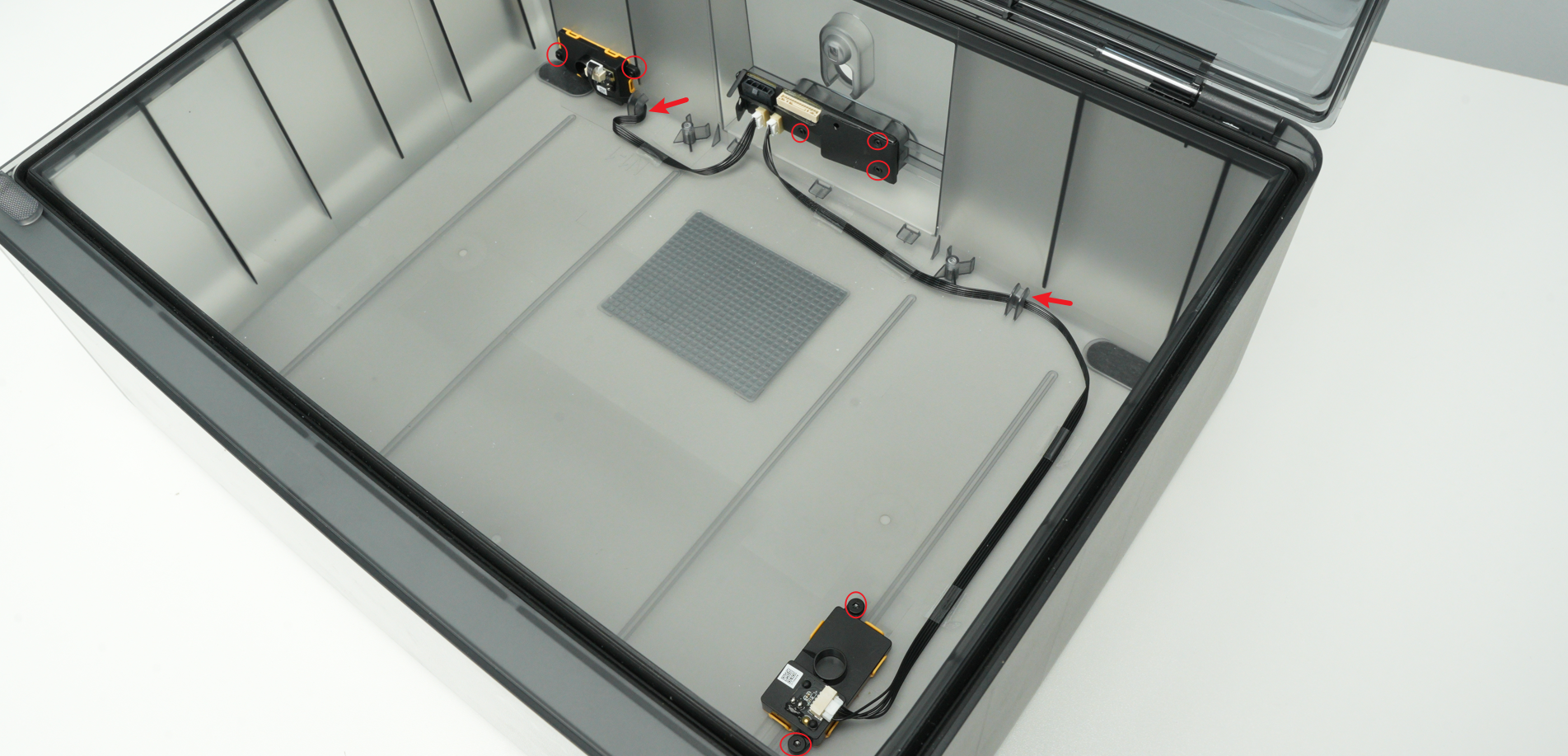
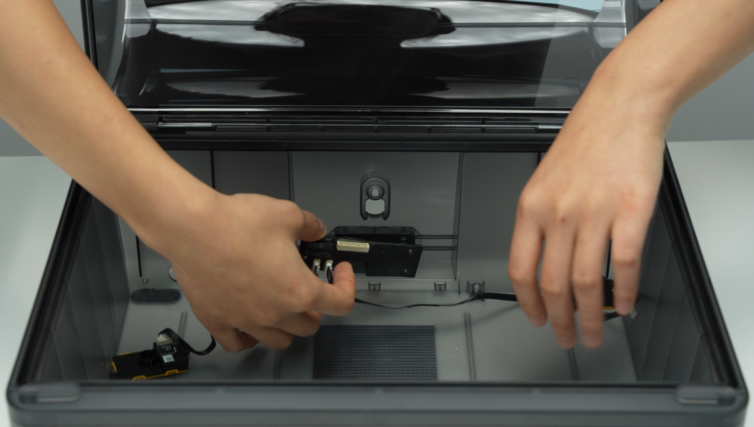
¶ Step 10 - Remove the power board, air intake and air vent, and cables
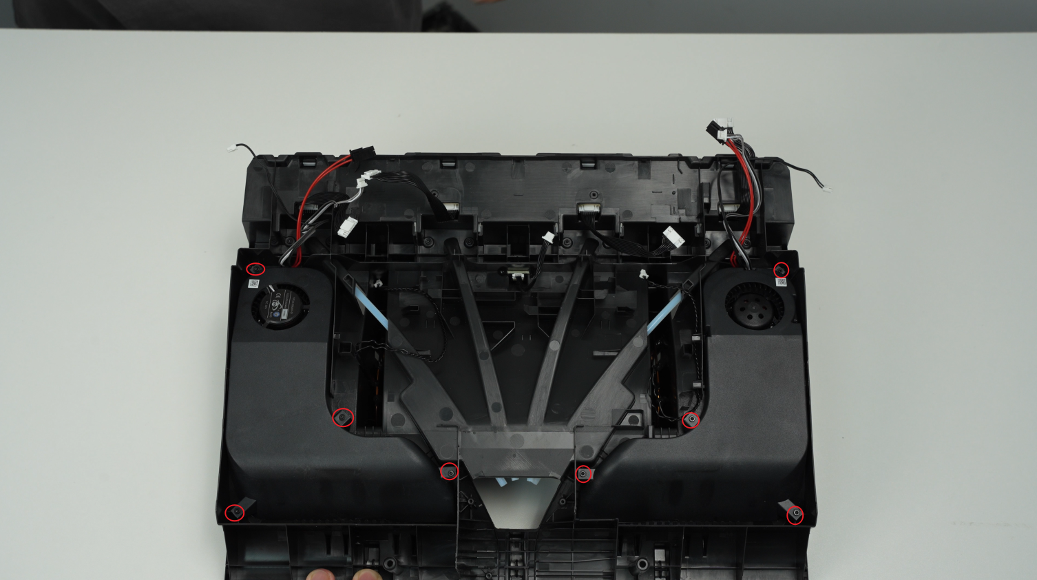
Remove the 3 screws B of the AMS power board, the 2 screws C of the air intake, and the 2 screws D of the air vent, and take out the power board, 2 air intake and air vent assemblies together.
 |
 |
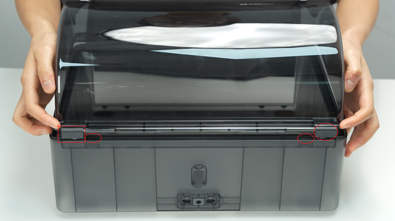
¶ Step 11 - Separate the top lid and the bottom cover unit
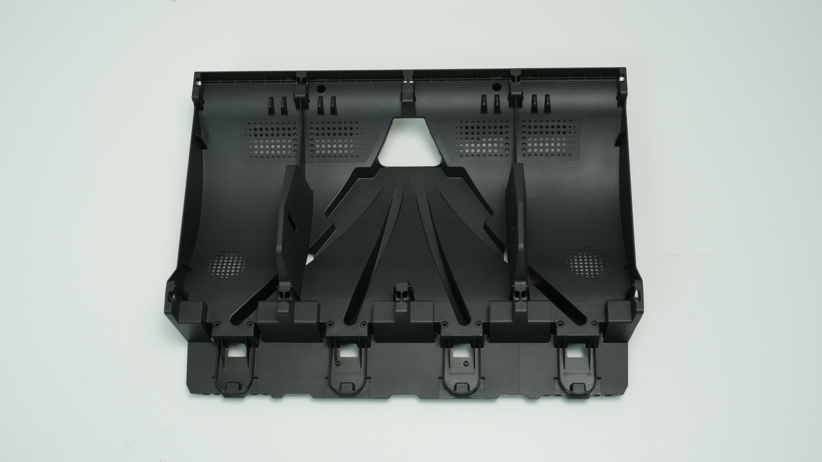
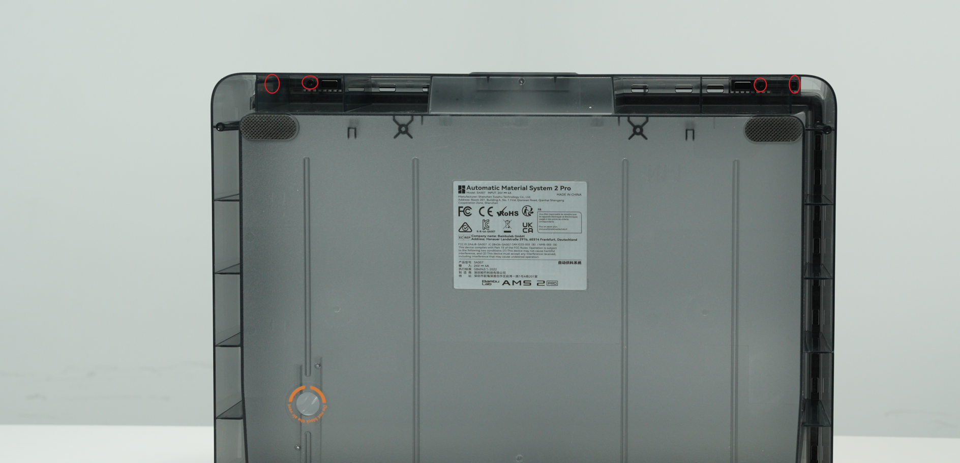
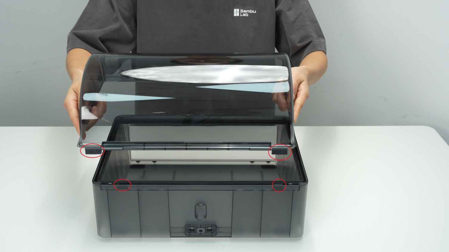
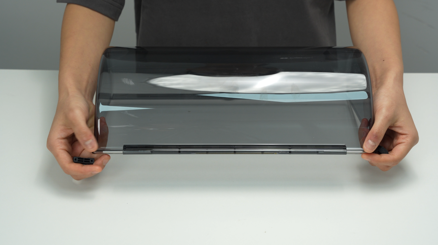
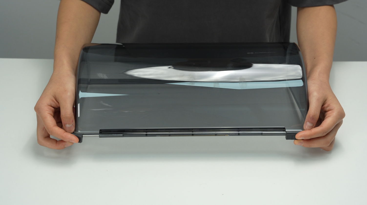
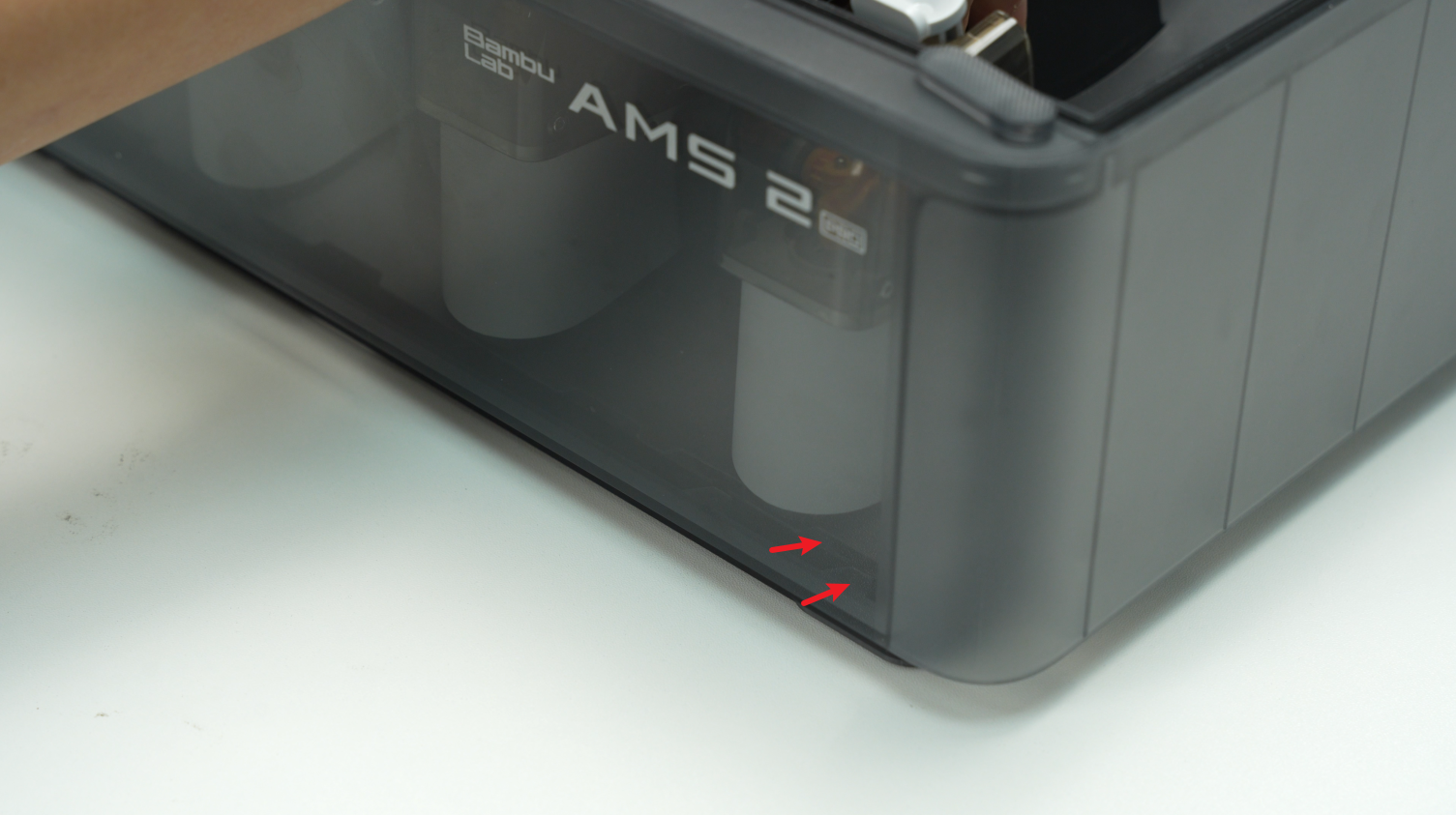
Remove 4 screws from the bottom of the AMS, 2 on each side, lift it up, remove the AMS top lid, and collect the 1 silicone pad on each side of the bottom cover unit, as well as the left and right hinges and their metal hinges on the top lid.
 |
 |
 |
 |
¶ Assembly Guide
¶ Step 1 - Install the top lid and the bottom cover unit
 |
 |
 |
 |
¶ Step 2 - Install the power board, air intake and air vent, and cables
Tighten the 3 screws B of the AMS power board, the 2 screws E of the air intake, and the 2 screws F of the air vent, and install the power board, air intake, and air vent together into the bottom cover.
Note: When installing the air intake and vent, pay attention to the direction. If the direction is wrong, the screw holes will not be aligned and the installation cannot be performed. The air intake socket at the bottom faces right, and the air vent socket on the side wall faces upward.
 |
 |
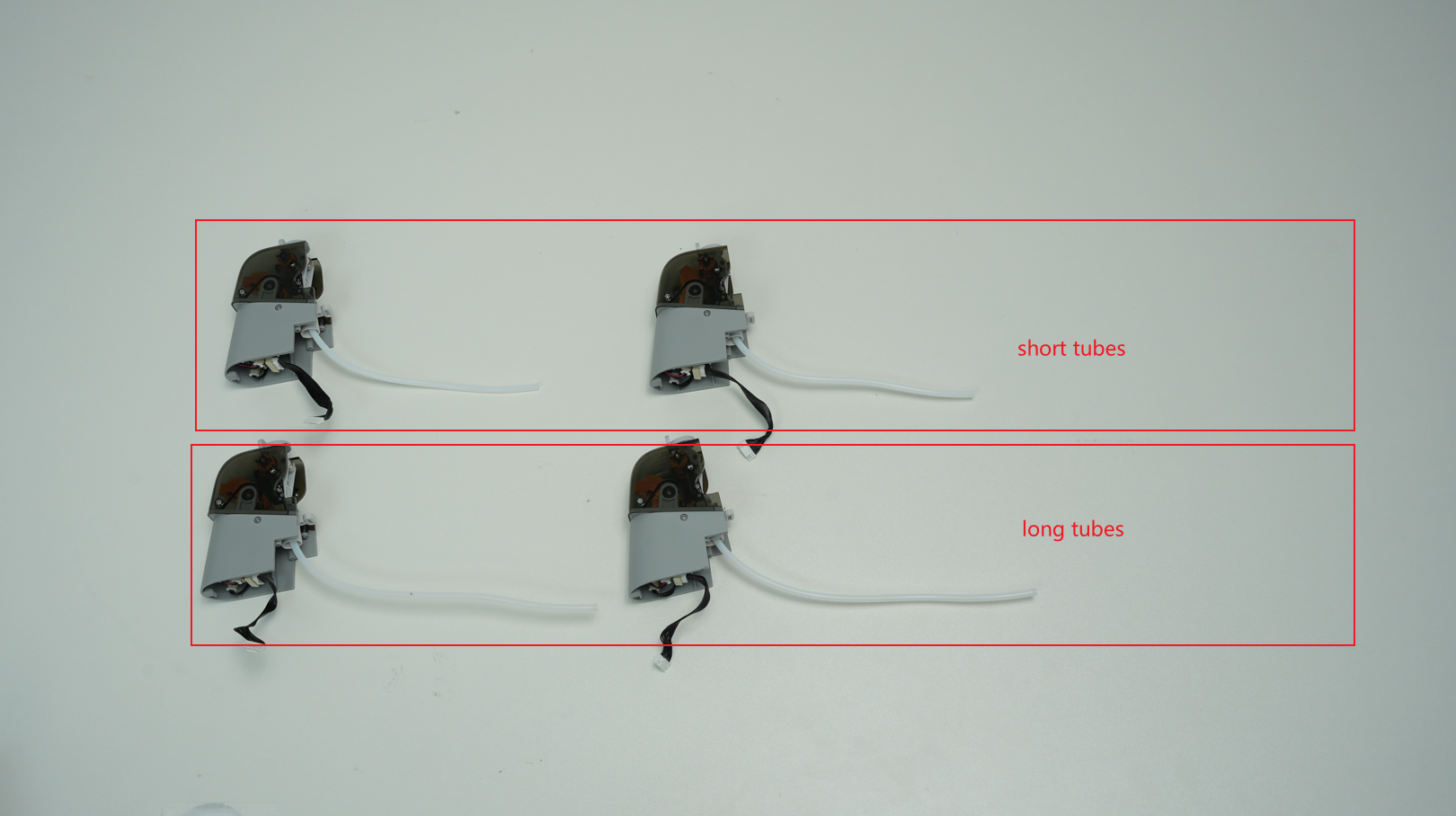
¶ Step 3 - Install 4 feeder units
The tubes connecting the feeder units of slots 1 and 4 are long, and the tubes of slots 2 and 3 are short.
 |
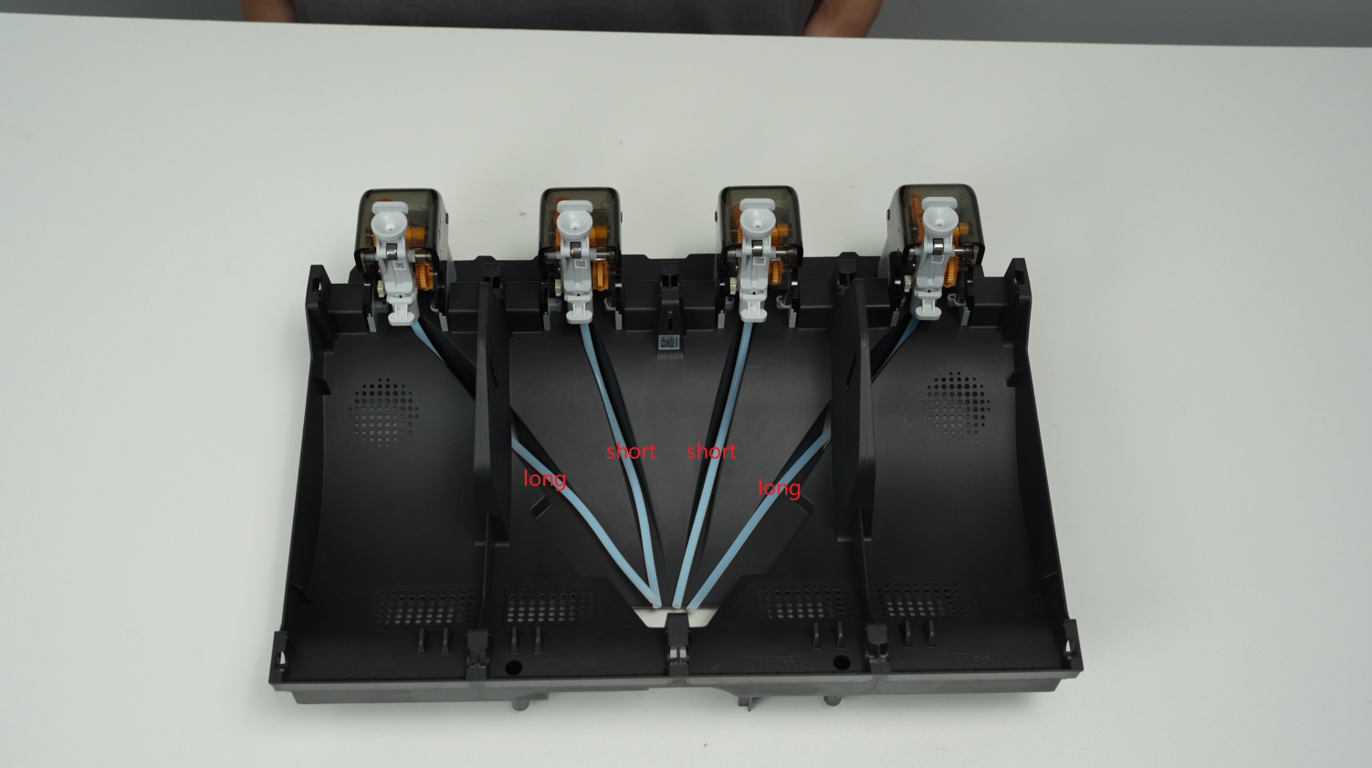 |
Select the feeder unit with the correct PTFE tube length, pass the cable through the hole to the AMS mainboard side, pass the PTFE tube from the tube groove on the upper surface to the filament hub, install the feeder unit in place, and tighten the 2 screws D to fix it. Install the other 3 feeder units in the same way.
 |
 |
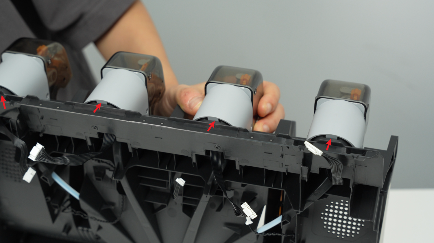
When installing the feeder units, you need to first align the front buckle. After it is in place, push it forward. When you hear a click, it means the screw hole is aligned in place, then lock the screw.
 |
 |
¶ Step 4 - Install the left and right drying units
Align the screw holes of the drying unit, press down the drying unit to lock the buckle, be careful not to press the cable, and lock the four screws D.
 |
 |
¶ Step 5 - Install the filament hub
Install two shock-proof gaskets, with the grooves of the gaskets flush with the upper edge of the filament hub.
 |
 |
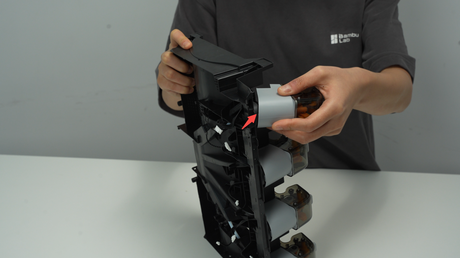
When reinstalling the filament hub, use your other hand to push the PTFE tube from the back to facilitate snapping the filament hub into place and aligning it with the screw hole. Pay attention to the shock-proof silicone strip on the filament hub to prevent it from being missed. After screwing in the 3 screws C, arrange the cables.
 |
 |
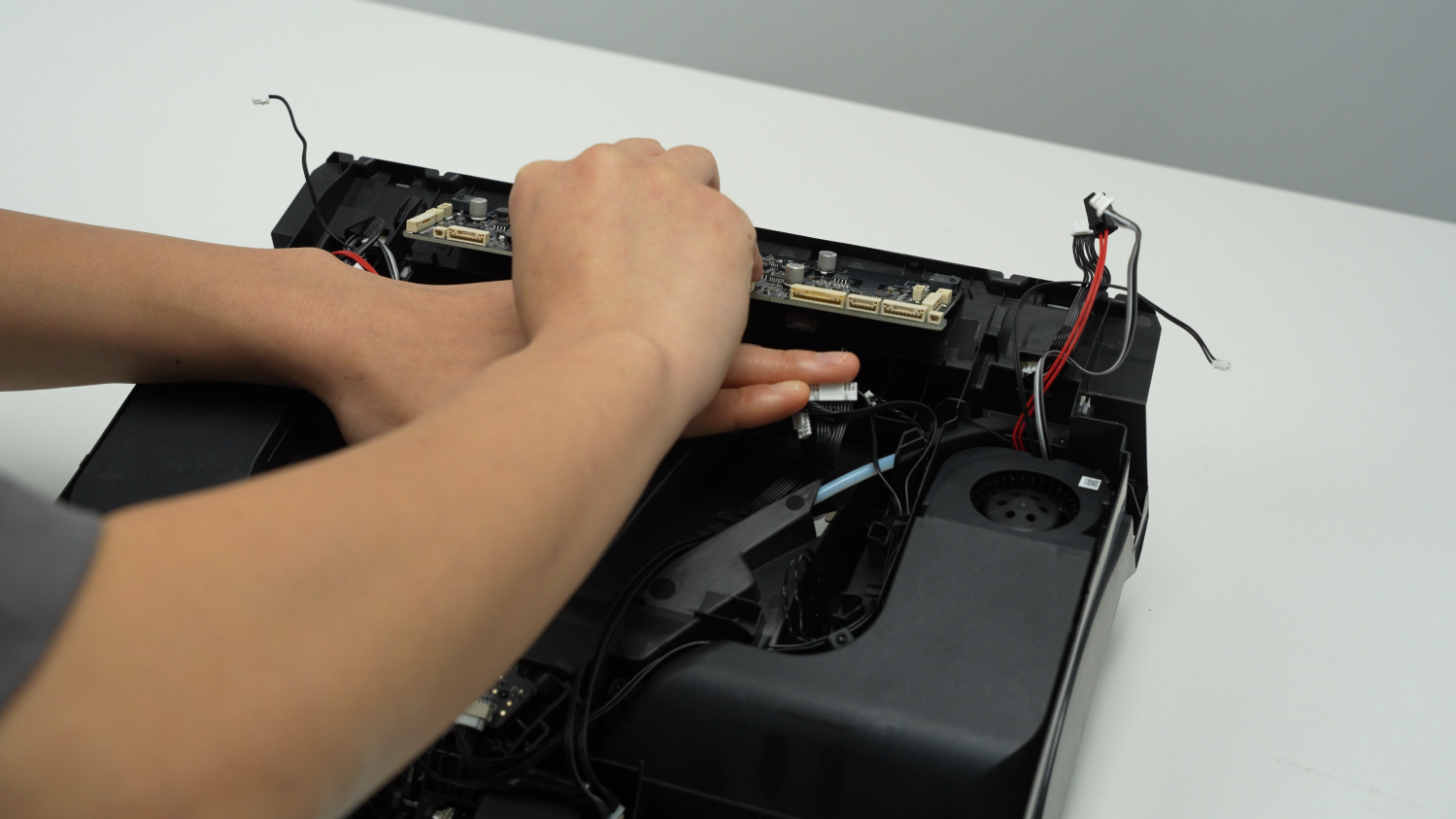
¶ Step 6 - Install the mainboard
Install the motherboard on the AMS middle frame. First, insert the AMS mainboard into the 3 clips on the upper edge from bottom to top, then press it down slightly and insert it into the 2 clips on the left and right.
Reminder: When installing the AMS mainboard, pay attention to checking the plug and do not press the plug on the back of the mainboard.
In this step, do not lock the 2 screws of the mainboard. After all the plugs are inserted in the next step, lock the screws.
 Pre-clipped into the top 3 clips |
 Press the 2 clips on the left and right |
¶ Step 7 - Connect 18 cables to the AMS mainboard
Connect 18 cables according to the marks or photos before disconnection. After confirming that the mainboard is installed and pressed by 5 clips, lock 2 screws.
Tips: Please check to make sure that each plug is inserted in place. For example, there will be a click sound after the feeder plugs are inserted in place, so as to avoid abnormal operation of AMS after power-on.
 |
 |
¶ Step 8 - Install the support sleeve assemblies and the PTFE tubes
Install 4 AMS middle frame active support sleeve assemblies and driven support sleeve assemblies for slots 1 and 4, and insert the PTFE tube.
Please note that the driven support sleeve assemblies for slots 2 and 3 do not need to be installed at this step to avoid blocking the screw holes of the middle frame.
When installing the AMS middle frame active support sleeve assembly, pay attention to align the wheel position of the feeder unit to prevent reverse installation, and ensure that the bearings at both ends are pressed down into place.
 |
 |
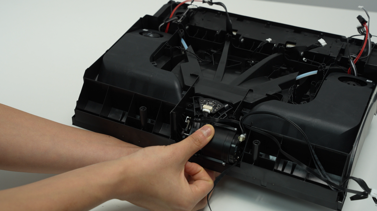
¶ Step 9 - Install the middle frame assembly and driven support sleeve assembly
Install the AMS middle frame into the AMS bottom cover and connect the signal cable and power cable to the AMS power board.
 |
 |
 |
 |
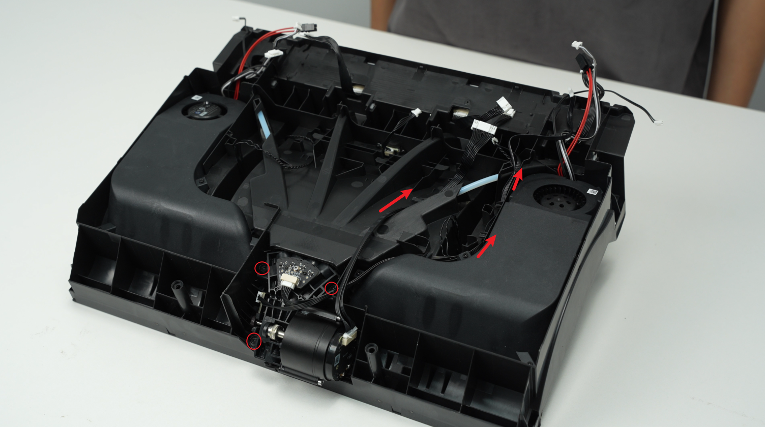
After the AMS middle frame is installed in place, screw in 2 screws to secure it. When installing the middle frame, you can push it forward a little, then squeeze the filament hub motor by hand and press it into the low hanging unit. Please note that the AMS bottom cover is considered properly installed only when a tab is embedded into the slot of the middle frame.
 |
 |
Install the 2 middle driven support sleeve assemblies, making sure the bearings at both ends of the 2 driven support sleeves are pressed into place.
 |
 |
¶ Step 10 - Install the PTFE tube release button
Press the PTFE tube release button back into the housing in the following direction, insert the buckle into the corresponding slot smoothly, and keep the black silicone housing embedded flat.
 |
 |
 |
 |
¶ Step 11 - Connect the PTFE tube
Check to make sure that the PTFE tube silicone bracket is aligned with the filament hole of the filament hub unit, and push the PTFE tube from the rear of the AMS. After installation, pull the PTFE tube to confirm that the PTFE tube is fixed.
 |
 |
¶ Calibration
Connect the power cable, connect the AMS to the printer, turn on the power, and start using the AMS to load filaments through the operation on the screen. If the loading can be completed and no error prompts appear during the entire loading process, the replacement is successful.
Otherwise, please check all connections and try again. If the problem persists, please contact Bambu Lab service team for further assistance.
¶ End Notes
We hope the detailed guide provided has been helpful and informative.
If this guide does not solve your problem, please submit a technical ticket, we will answer your questions and provide assistance.
If you have any suggestions or feedback on this Wiki, please leave a message in the comment area. Thank you for your support and attention!