¶ Applicable models
AMS 2 Pro (Hereinafter referred to as AMS)
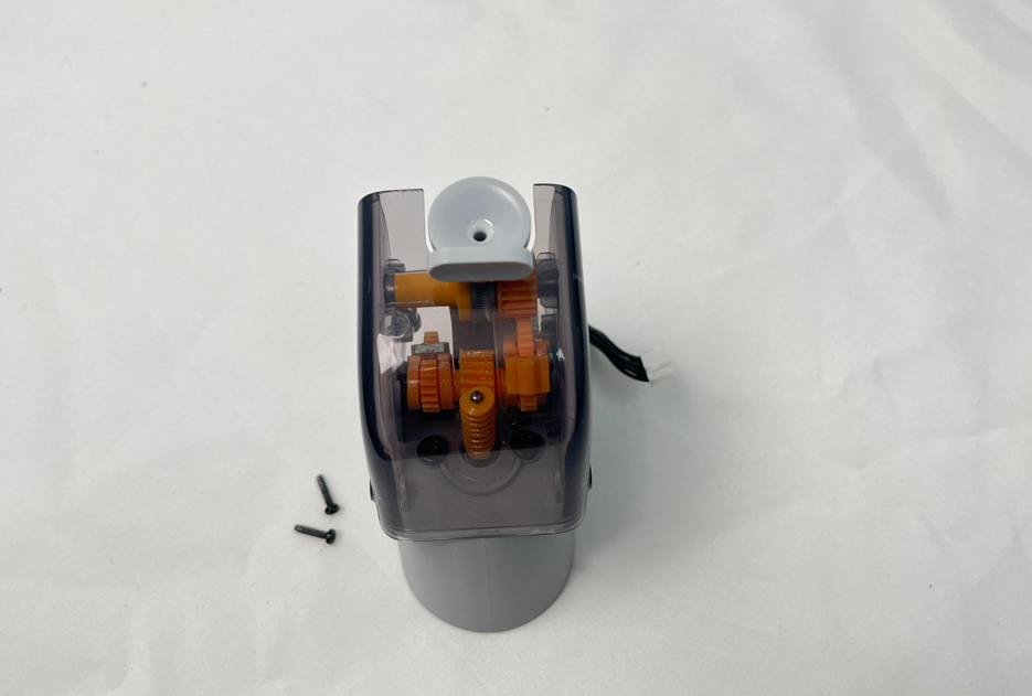
¶ AMS 2 Pro Feeder Unit
The feeder unit is installed on the AMS and is a feeding device that provides the first-order driving force for the AMS. There are 4 feeder units in one AMS.
¶ When to use?
When there is a wheel failure, motor failure or visible internal damage, or the detection switch is erratic.
¶ Tools and materials needed
-
New AMS 2 Pro Power Board
-
H2.0 Allen key
-
H1.5 Allen key
-
20 minutes
¶ Screws List
¶ Safety Warning
IMPORTANT!
It's crucial to power off the printer before conducting any maintenance work, including work on the printer's electronics and tool head wires. Performing tasks with the printer on can result in a short circuit, leading to electronic damage and safety hazards.
During maintenance or troubleshooting, you may need to disassemble parts, including the hotend. This exposes wires and electrical components that could short circuit if they contact each other, other metal, or electronic components while the printer is still on. This can result in damage to the printer's electronics and additional issues.
Therefore, it's crucial to turn off the printer and disconnect it from the power source before conducting any maintenance. This prevents short circuits or damage to the printer's electronics, ensuring safe and effective maintenance. For any concerns or questions about following this guide, we recommend submitting a technical ticket regarding your issue and we will do our best to respond promptly and provide the assistance you need.
Before starting, make sure the AMS is disconnected from the printer.
¶ Remove the feeder unit
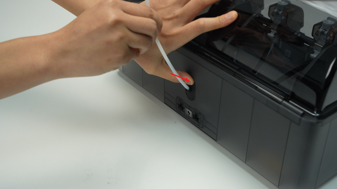
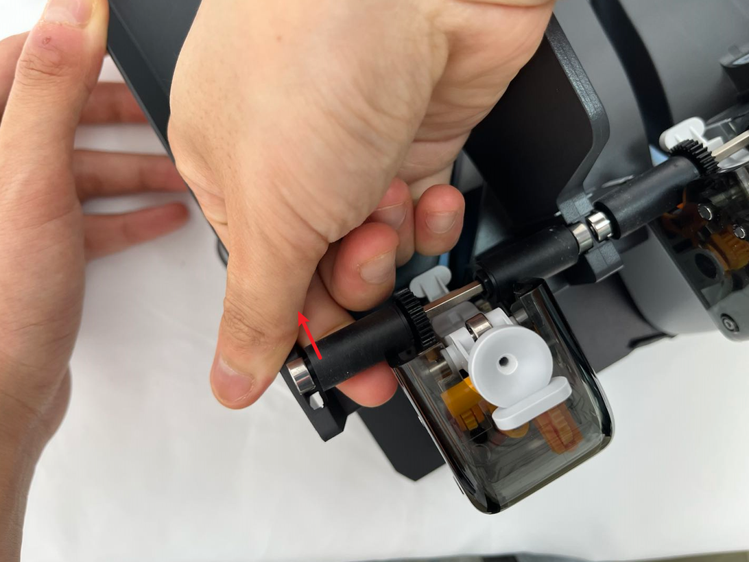
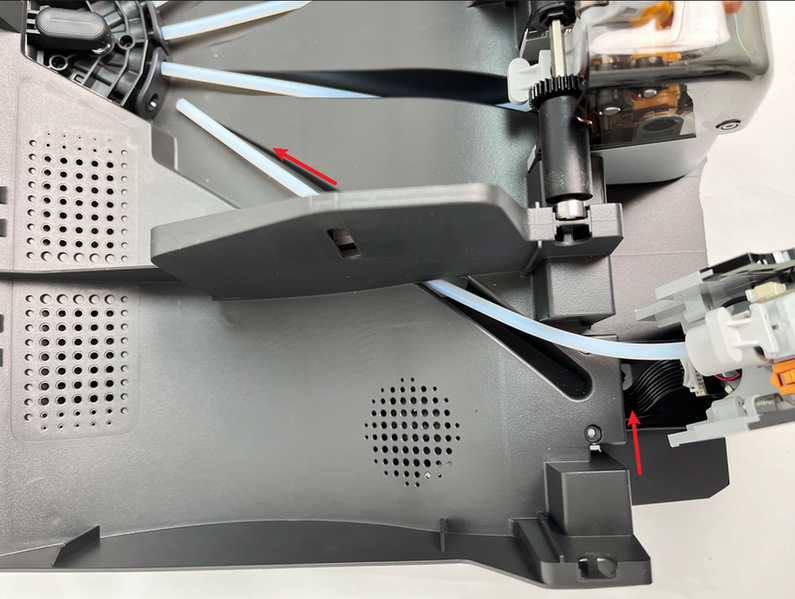
¶ Step 1 - Remove the PTFE tube on the back of the AMS
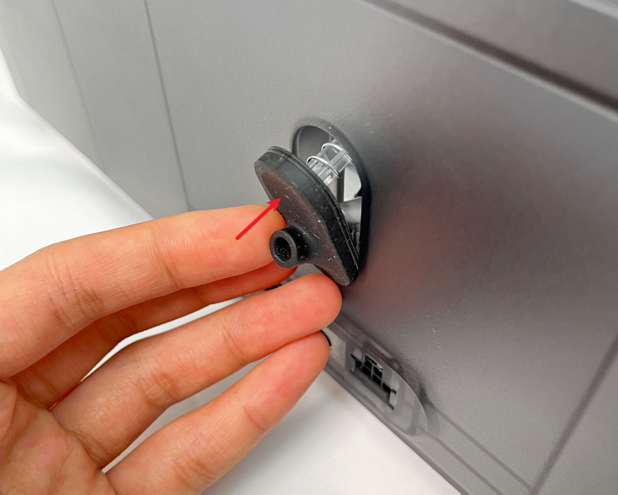
Press the PTFE tube release button from the back of the AMS to unlock the fitting, then pull the PTFE tube out from the back of the AMS.
¶ Step 2 - Pull out the PTFE tube release button
Pinch the clip from the inside of the lower cover to automatically pop open the PTFE tube release button, and then pull out the PTFE tube release button from the back of the AMS.
When squeezing the buckle, use your other hand to hold the PTFE tube from the back of the AMS to release the switch to prevent the spring from being ejected and lost.
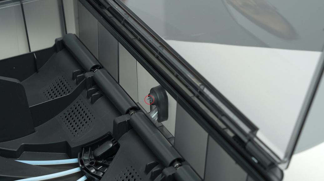
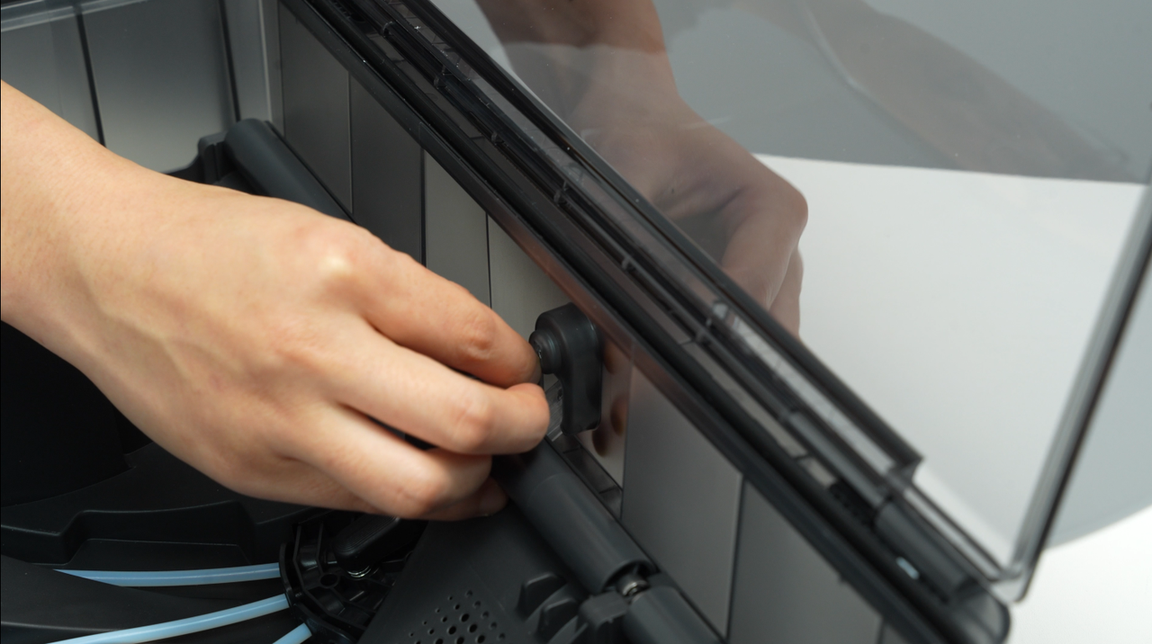
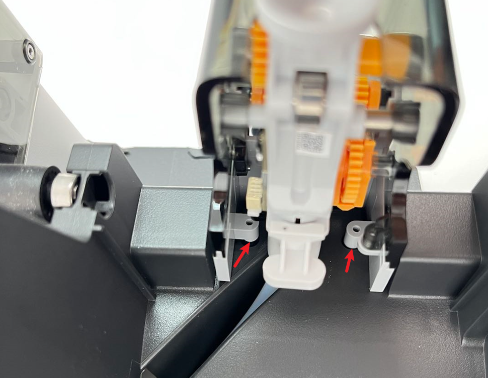
¶ Step 3 - Remove the AMS main frame assembly
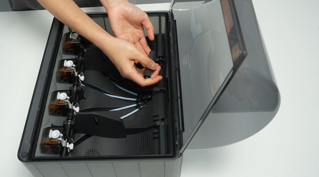
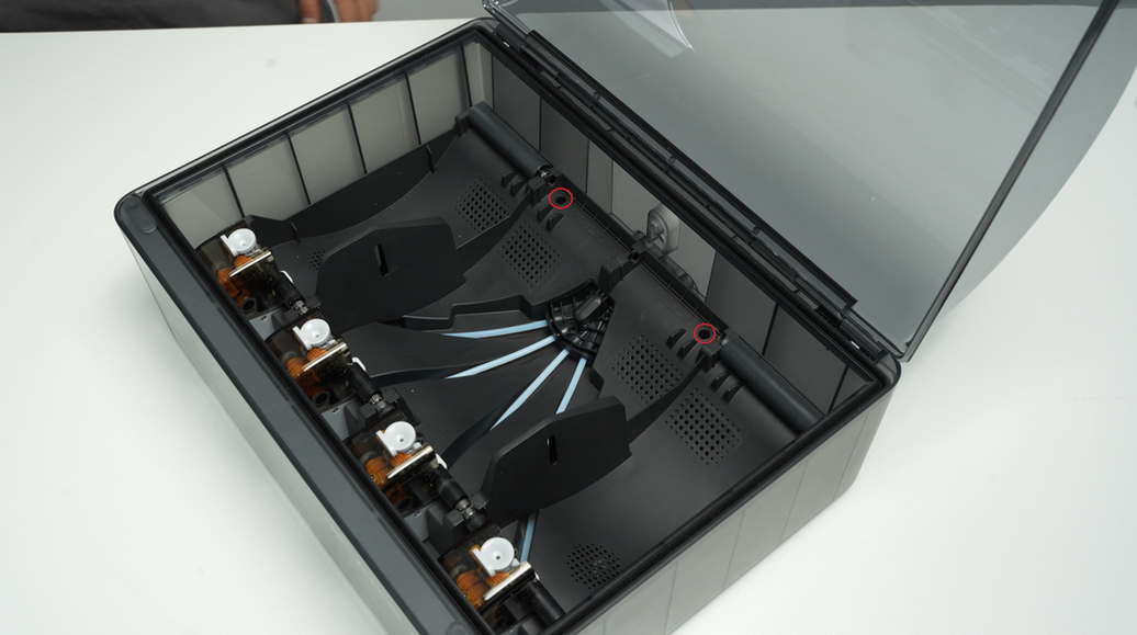
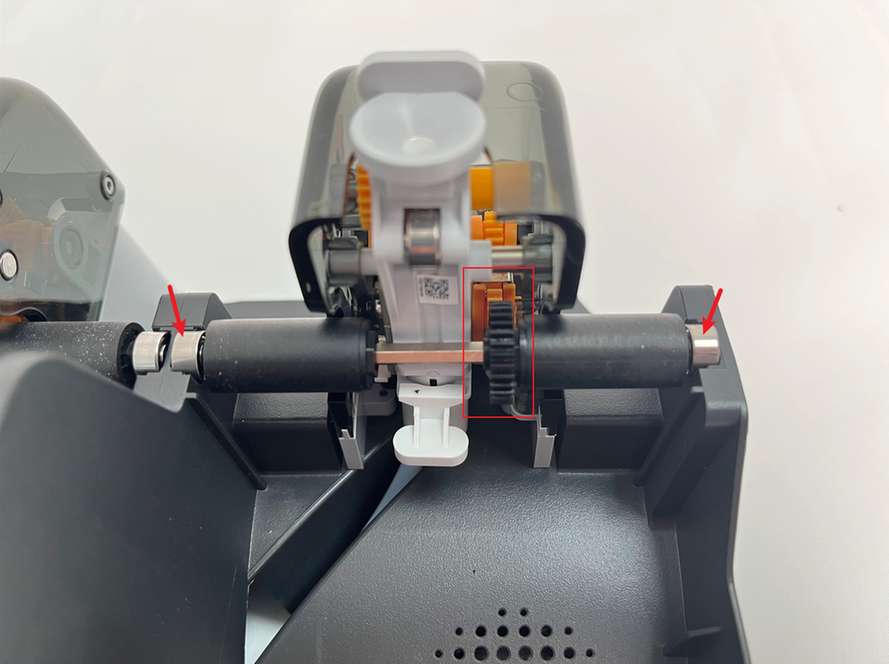
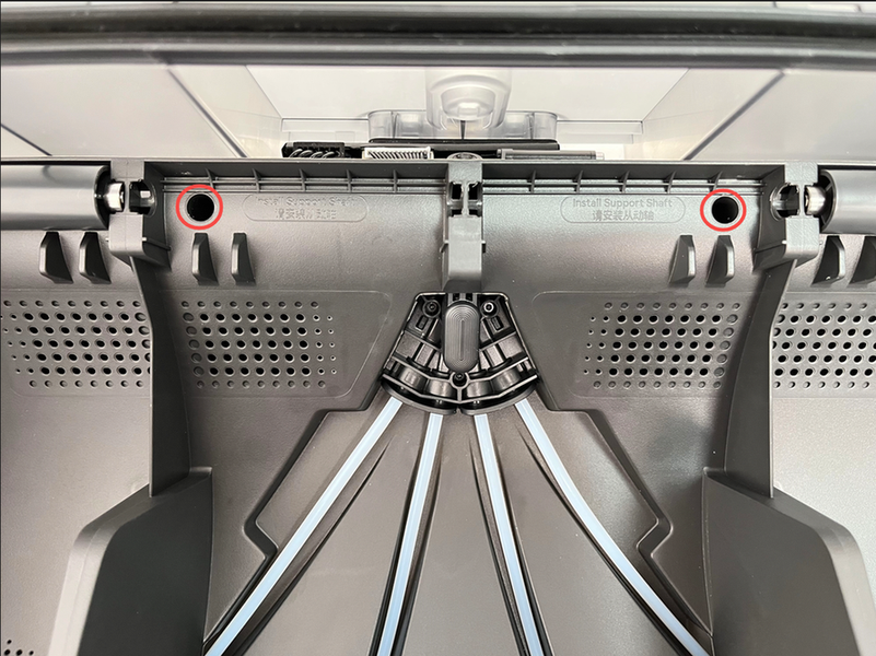
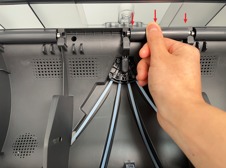
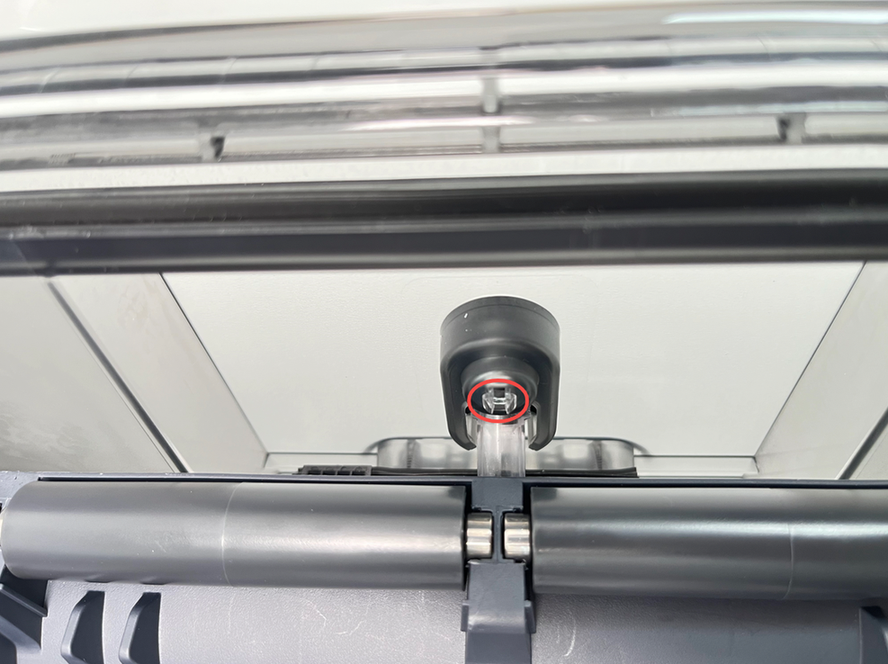
Remove the driven support sleeve assembly of the two middle slots to expose the two screw holes. When removing the bearing sleeve, be careful with the bearings at both ends to avoid losing them.
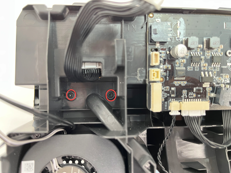
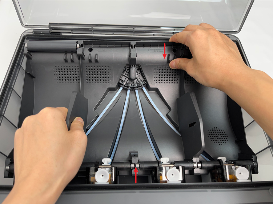
Remove the two screws A that secure the AMS main frame.
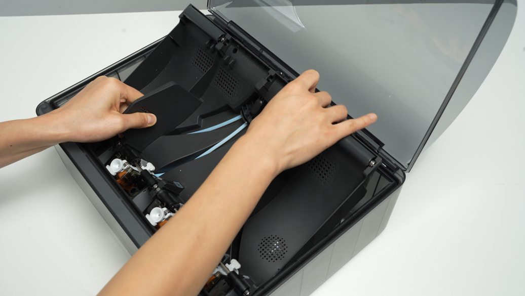
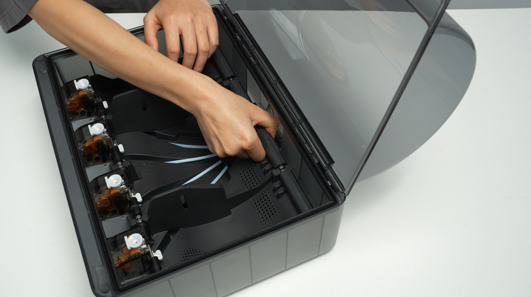
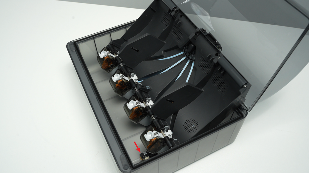
Lift the rear part of the main frame completely and place it vertically on the lower cover of the AMS. Note that there are cables connected, so do not operate violently. When lifting, it is recommended to lift the front part of the main frame first, and then push it forward to make room for the rear part of the frame.
When placing the AMS main frame vertically, avoid the electronic components of the vent to prevent them from being crushed.
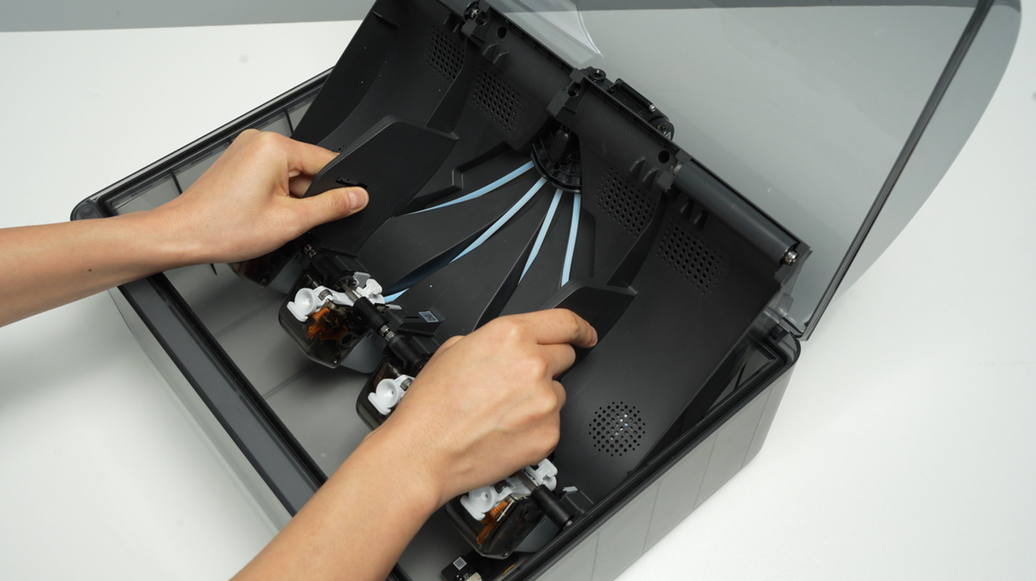
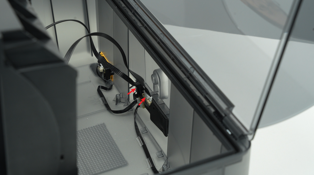
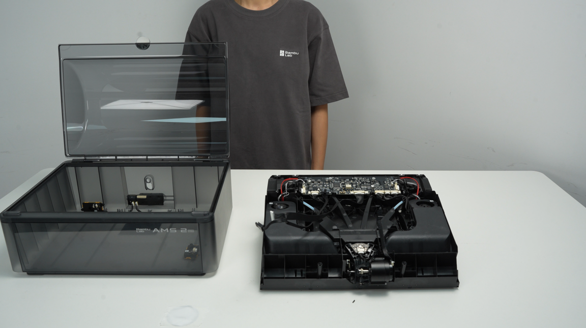
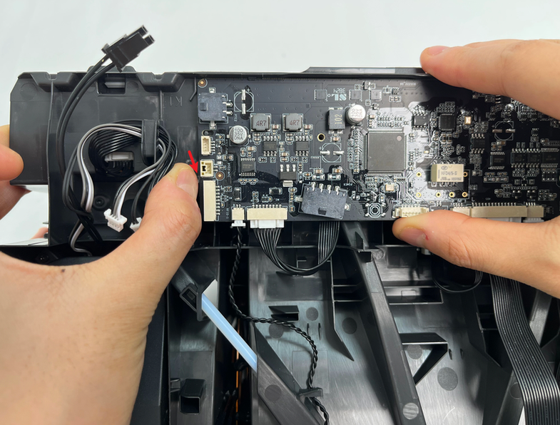
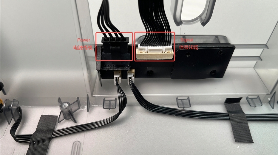
Unlock the plug buckle, unplug the signal cable and power cable on the AMS power board, and lift out the AMS main frame assembly as a whole.
¶ Step 4 - Remove the AMS main frame active support sleeve assembly
Remove the AMS main frame active support sleeve assembly at the corresponding position of the feeder unit that need to be replaced.
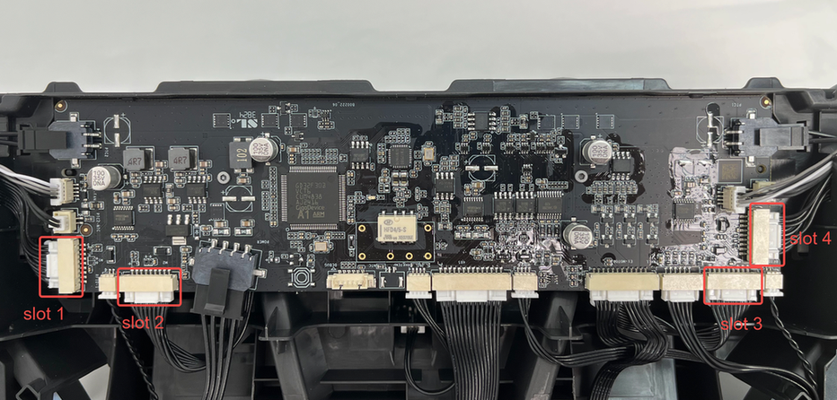
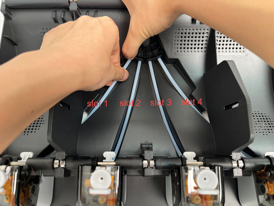
¶ Step 5 - Disconnect the cables and PTFE tubes at the filament hub
Disconnect the cables between the feeder units and the mainboard, as well as the connection between the PTFE tubes of the feeder units and the AMS filament hub. For example, if you are replacing the feeder units in slot 1, disconnect the cables and PTFE tubes at the corresponding positions.


¶ Step 6 - Remove the feeder unit
Remove the 2 fixing screws B at the corresponding positions according to the feeder units that need to be replaced. If you replace the feeder unit 1 & 4, you need to pull out the cables from the cable channel. Unplug the plug, pull out the cables, unscrew the feeder unit screws, push the feeder unit backwards to unlock the front clip and remove it.
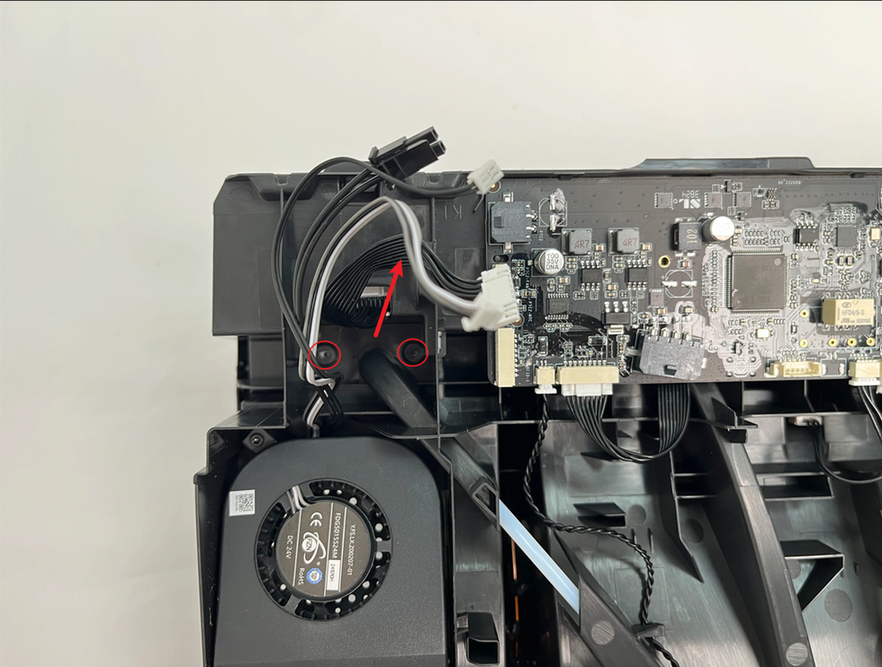
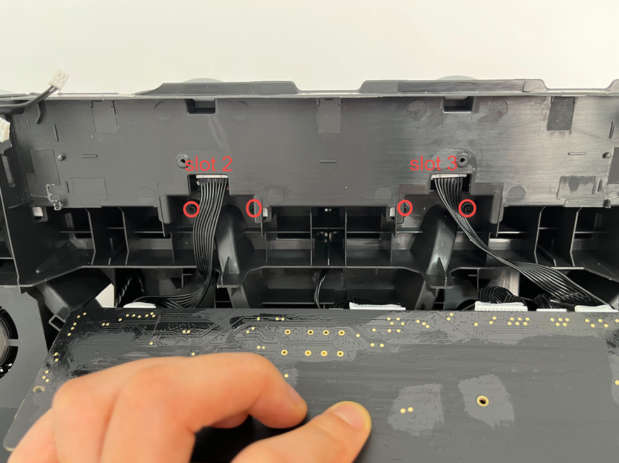
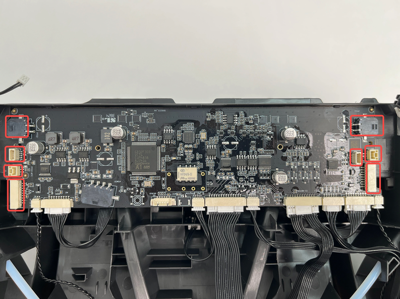
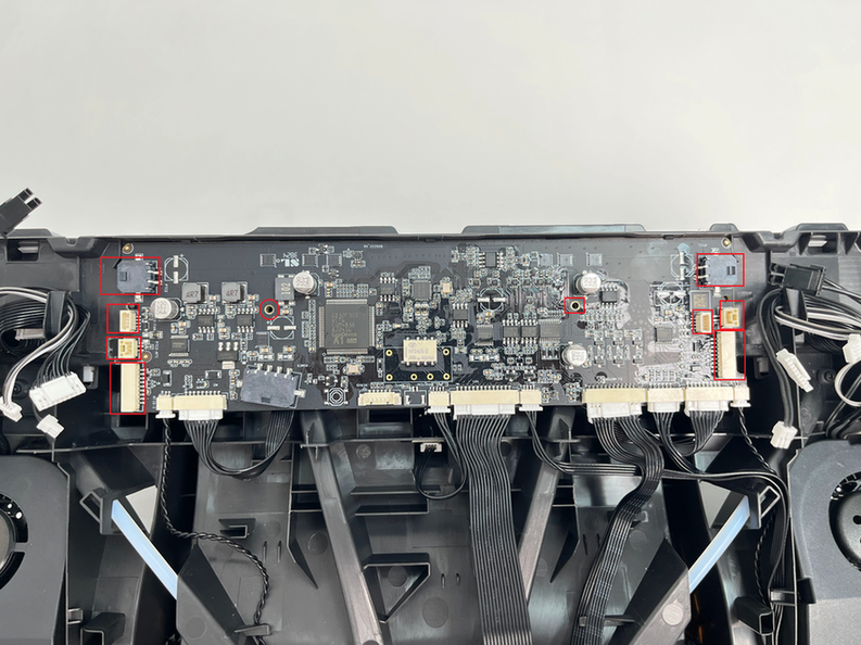
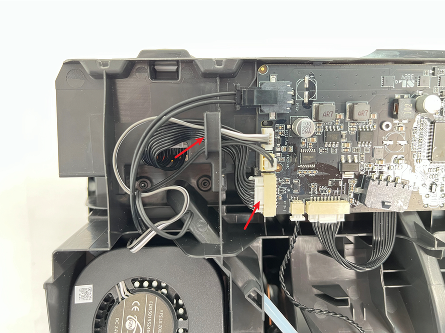
It should be noted here that if you replace the feeder units of slots 2 and 3, you need to loosen the 2 mainboard screws C first, remove the 4 plugs vertically on the left and right sides of the mainboard from the cable channel clips, turn over the mainboard, and then you can unscrew the feeder units of slots 2 and 3.
After making sure that the 2 screws are removed and the cables are untangled (when replacing the feeder unit 1 & 4, pay special attention to the need to untangle the cables), tilt the feeder units toward your body, release the clips at the front, and remove it.

¶ Step 7 - Remove the PTFE tube for feeder unit
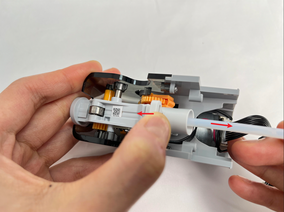
Lift the quick coupler button in the opposite direction of the PTFE tube to release the clip, and then pull out the PTFE tube.
¶ Install the feeder unit
¶ Step 1 - Install the PTFE tube for feeder unit
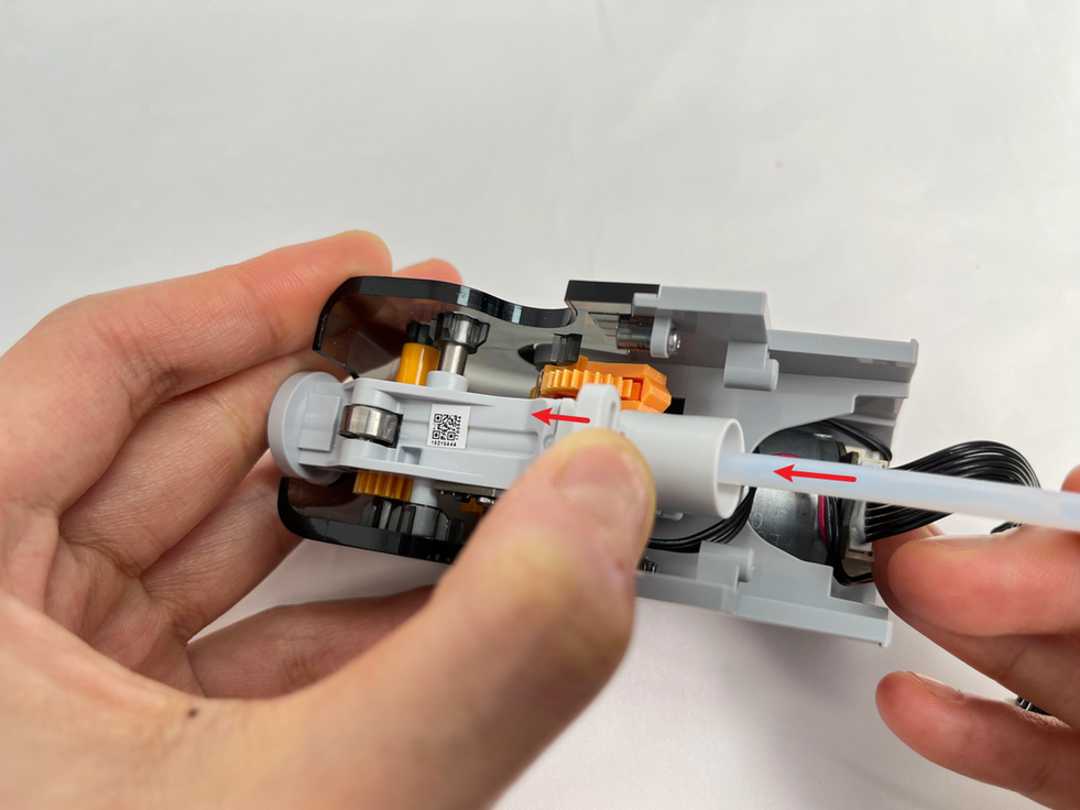
Lift the quick coupler button in the direction away from the PTFE tube to release the clip, and then push the PTFE tube forward.
¶ Step 2 - Remove the feeder unit
Pass the cable through the hole to the mainboard side, pass the PTFE tube from the tube groove to the filament hub, install the feeder unit in place, and lock in 2 screws to fix it.
When installing the feeder unit, you need to align the clip in front first, and after it is in place, push it forward. When you hear a click, it means that the screw hole is aligned in place, and then lock in the screw.

¶ Step 3 - Connect cables and PTFE tubes at the filament hub
Connect all cables and PTFE tubes. Connect the cables to the corresponding connectors on the mainboard and the PTFE tubes to the corresponding ports on the AMS filament hub.
Tips: Please insert the cable into the cable clip first, and then insert the plug. When arranging the cables, you can first insert the cables of feeder unit. Make sure the feeder unit plugs are properly inserted to avoid the feeder unit not working after power is turned on. There will be a click sound after it is inserted into place.
¶ Step 4 - Install the AMS main frame active support sleeve assembly
When installing the AMS main frame active support sleeve assembly, pay attention to aligning the wheel position of the feeder unit to prevent reverse installation, and ensure that the bearings at both ends are pressed down into place.

¶ Step 5 - Install the main frame assembly and driven support sleeve assembly
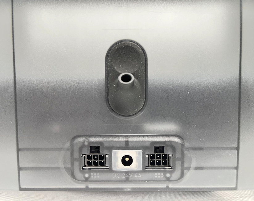
Install the AMS main frame assembly into the AMS lower cover and connect the signal cable and power cable to the AMS power board.
Align the tabs of the bottom cover unit with the slots of the middle frame, and then insert and install.

After the AMS main frame is installed in place, tighten the two screws to secure it.
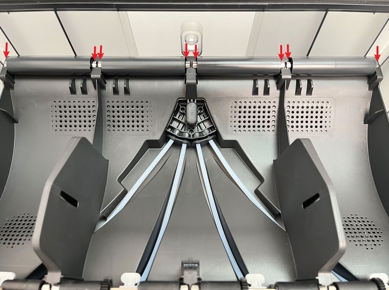
Install the two middle driven support sleeve assemblies, making sure that the bearings on both ends of all support shafts are pressed into place.
¶ Step 6 - Install the PTFE tube release button
Press the PTFE tube release button back into the housing in the following direction, insert the buckle into the corresponding slot smoothly, and keep the black silicone housing embedded flat.
¶ Step 7 - Connect the PTFE tube
Check to make sure that the PTFE tube silicone bracket is aligned with the filament hole of the filament hub unit, and push the PTFE tube from the rear of the AMS. After installation, pull the PTFE tube to confirm that the PTFE tube is fixed.


¶ Calibration
Connect the power cable, connect the AMS to the printer, turn on the power, and start using the AMS to load filaments through the operation on the screen. If the loading can be completed and no error prompts appear during the entire loading process, the replacement is successful.
Otherwise, please check all connections and try again. If the problem persists, please contact Bambu Lab service team for further assistance.
¶ End Notes
We hope the detailed guide provided has been helpful and informative.
If this guide does not solve your problem, please submit a technical ticket, we will answer your questions and provide assistance.
If you have any suggestions or feedback on this Wiki, please leave a message in the comment area. Thank you for your support and attention!