¶ AMS HT

This document provides guidance and precautions for the complete disassembly and assembly of the AMS HT. The procedures for replacing components during disassembly can also be referenced here.
¶ Component List
| AMS HT Main Frame | AMS HT Heating Unit | AMS HT Air Inlet Unit |
| AMS HT Bottom Cover Unit | AMS HT Mainboard | AMS HT Power Socket |
| AMS HT Top Lid | AMS HT Power Board | AMS HT Driven Support Shaft Assembly |
| AMS HT Screen | Feeder Hall Sensor Assembly | 3520 AMS Internal Assist Motor |
| AMS HT Filament Retraction Assembly | AMS HT Active Support Shaft Assembly | AMS HT RFID Coil |
| PTFE Tube | AMS HT Cable Pack (4-in-1) | AMS HT Status Hall Sensor |
| AMS HT Feeder Unit |
¶ Required Tools and Materials
- H2.0 Hex Wrench
- H1.5 Hex Wrench
- 50 minutes
¶ Safety Warning
It's crucial to power off the printer before conducting any maintenance work, including work on the printer's electronics and tool head wires. Performing tasks with the printer on can result in a short circuit, leading to electronic damage and safety hazards.
During maintenance or troubleshooting, you may need to disassemble parts, including the hotend. This exposes wires and electrical components that could short circuit if they contact each other, other metal, or electronic components while the printer is still on. This can result in damage to the printer's electronics and additional issues.
Therefore, it's crucial to turn off the printer and disconnect it from the power source before conducting any maintenance. This prevents short circuits or damage to the printer's electronics, ensuring safe and effective maintenance. For any concerns or questions about following this guide, open a new ticket in our Support Page and we will do our best to respond promptly and provide the assistance you need.
¶ Disassembly Guide
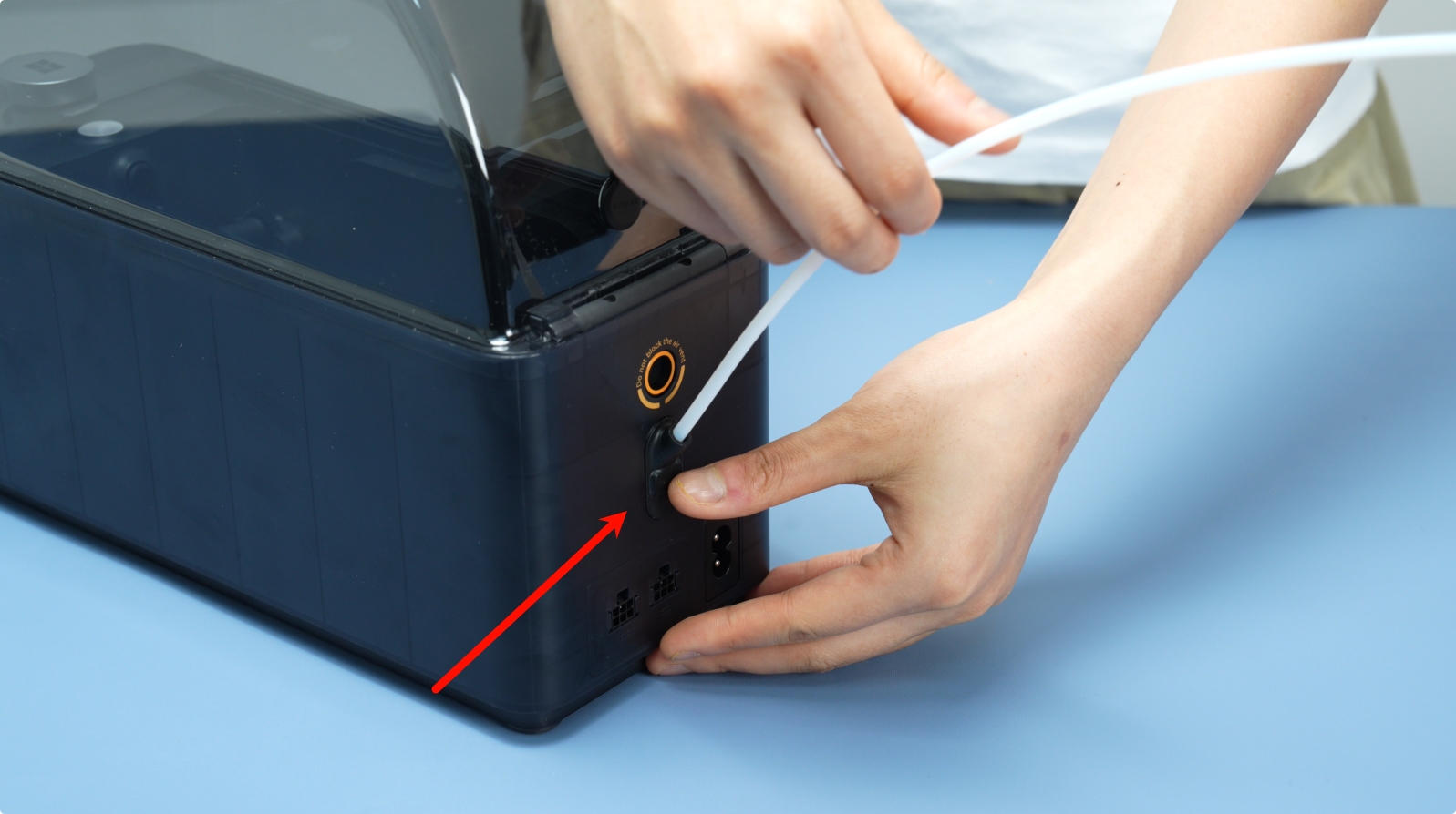
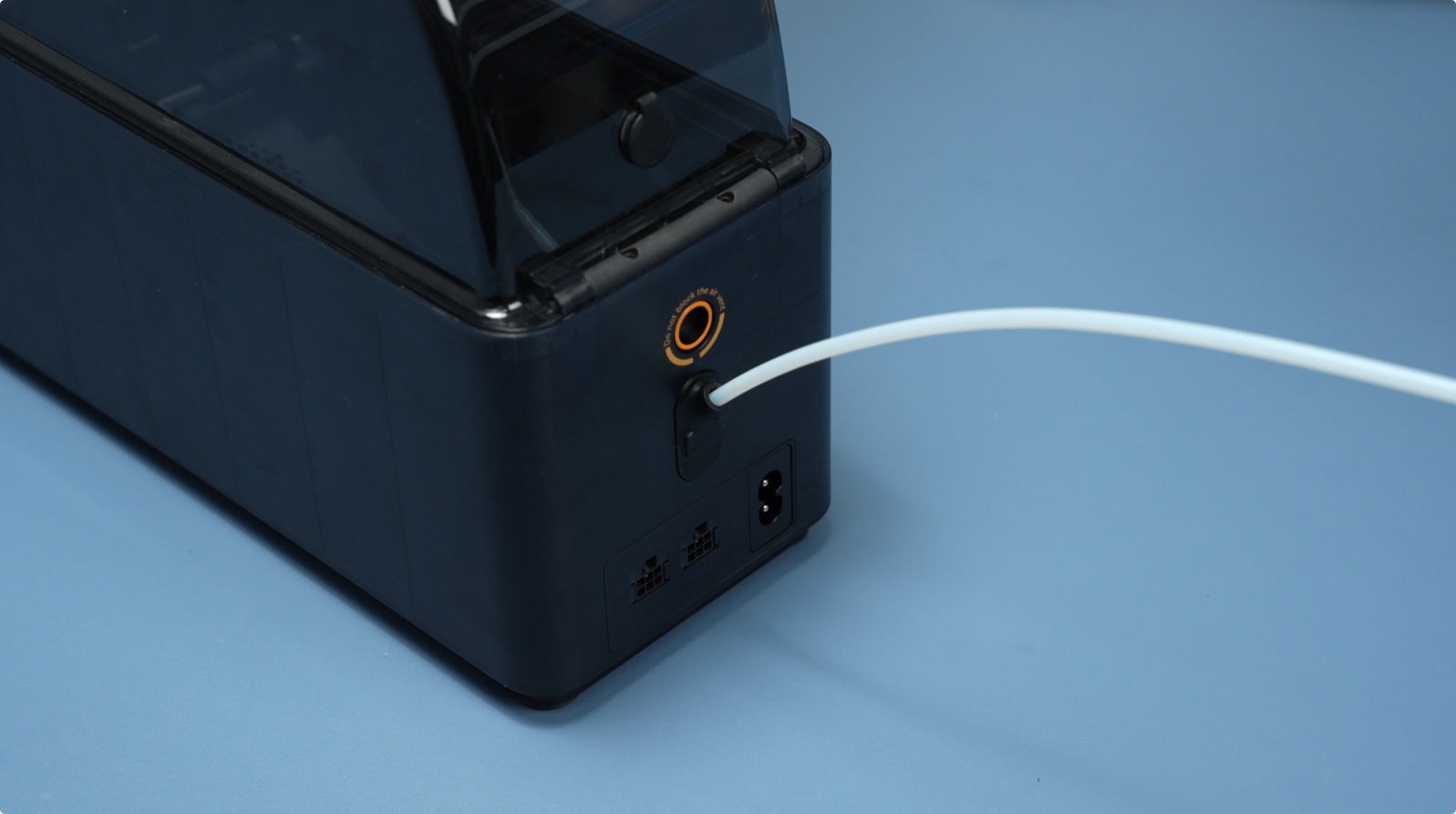
¶ 1. Remove the PTFE Tube from AMS HT Back
Press the PTFE tube release button on the back of the AMS HT to unlock the connector, then pull out the PTFE tube.
¶ 2. Remove the AMS HT Main Frame
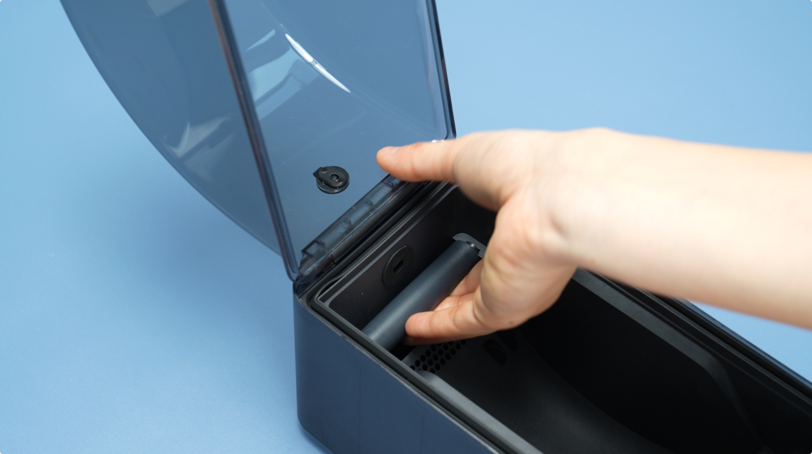
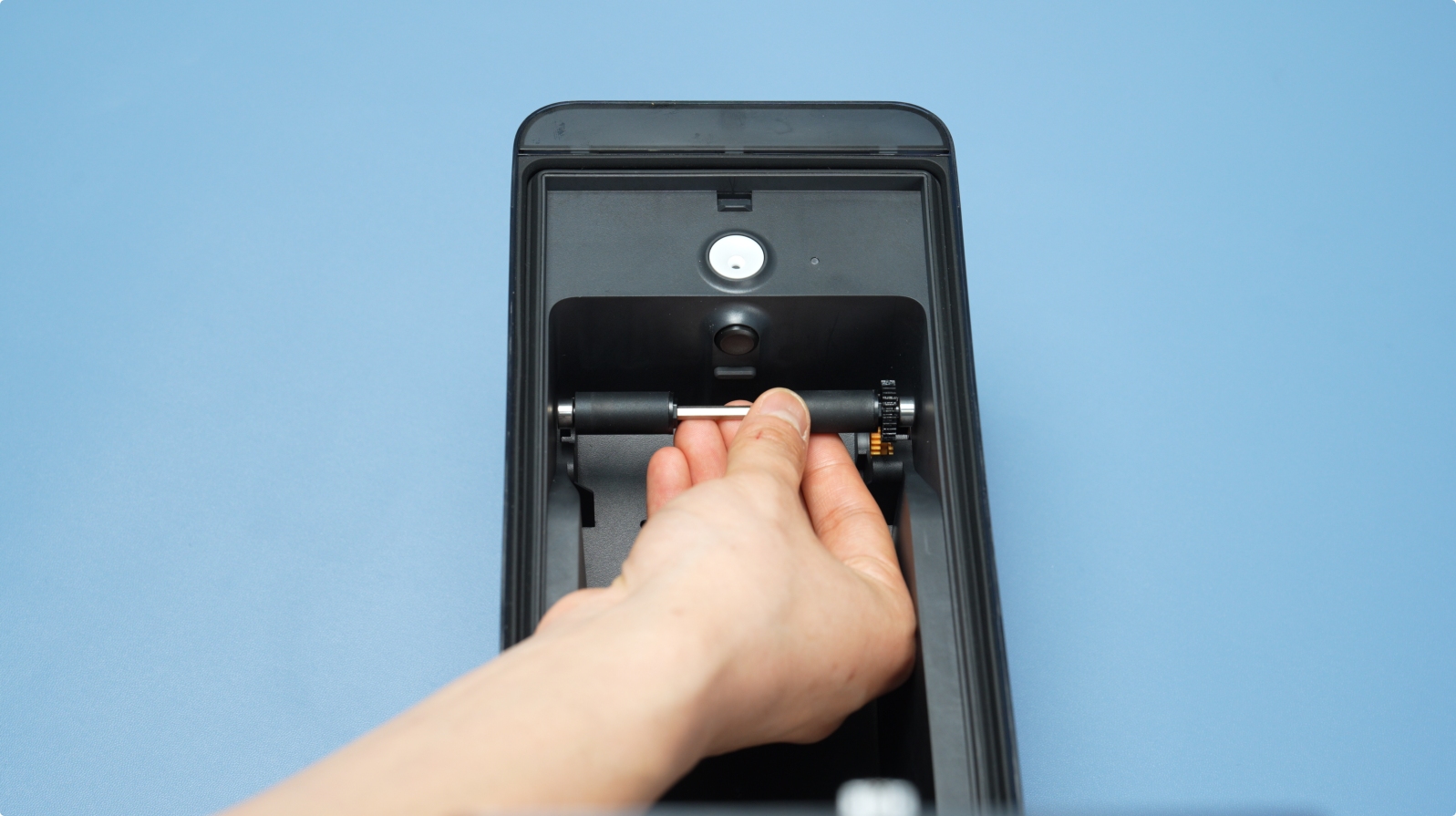
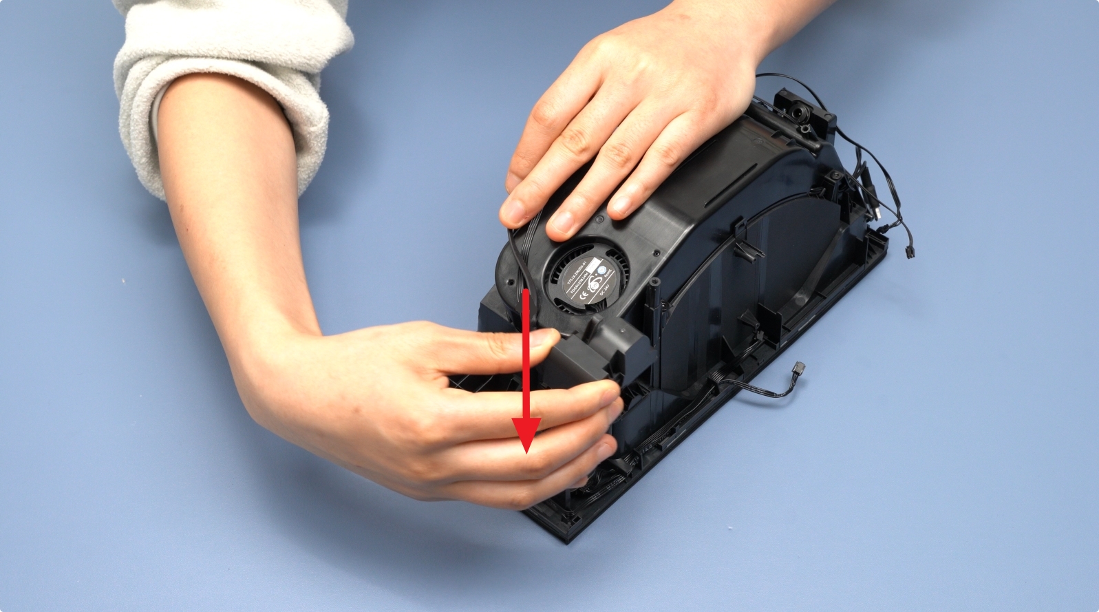
First, remove the Driven Support Shaft and Active Support Shaft from the material slot. Be careful with the bearings at both ends when removing the bearing sleeves.
 |
 |
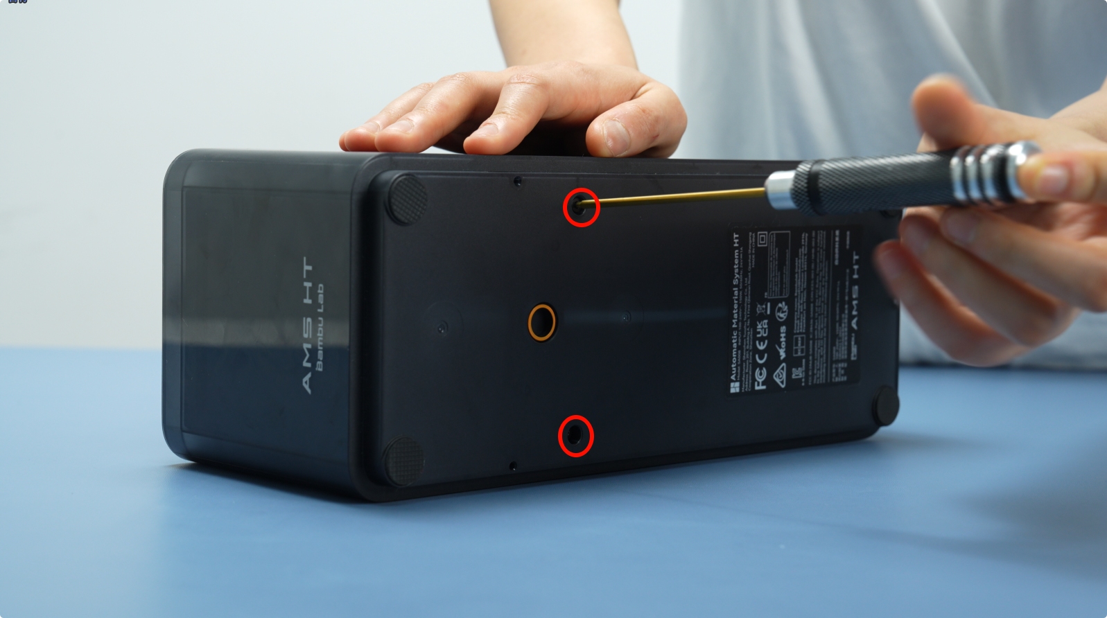
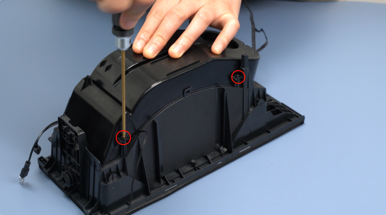
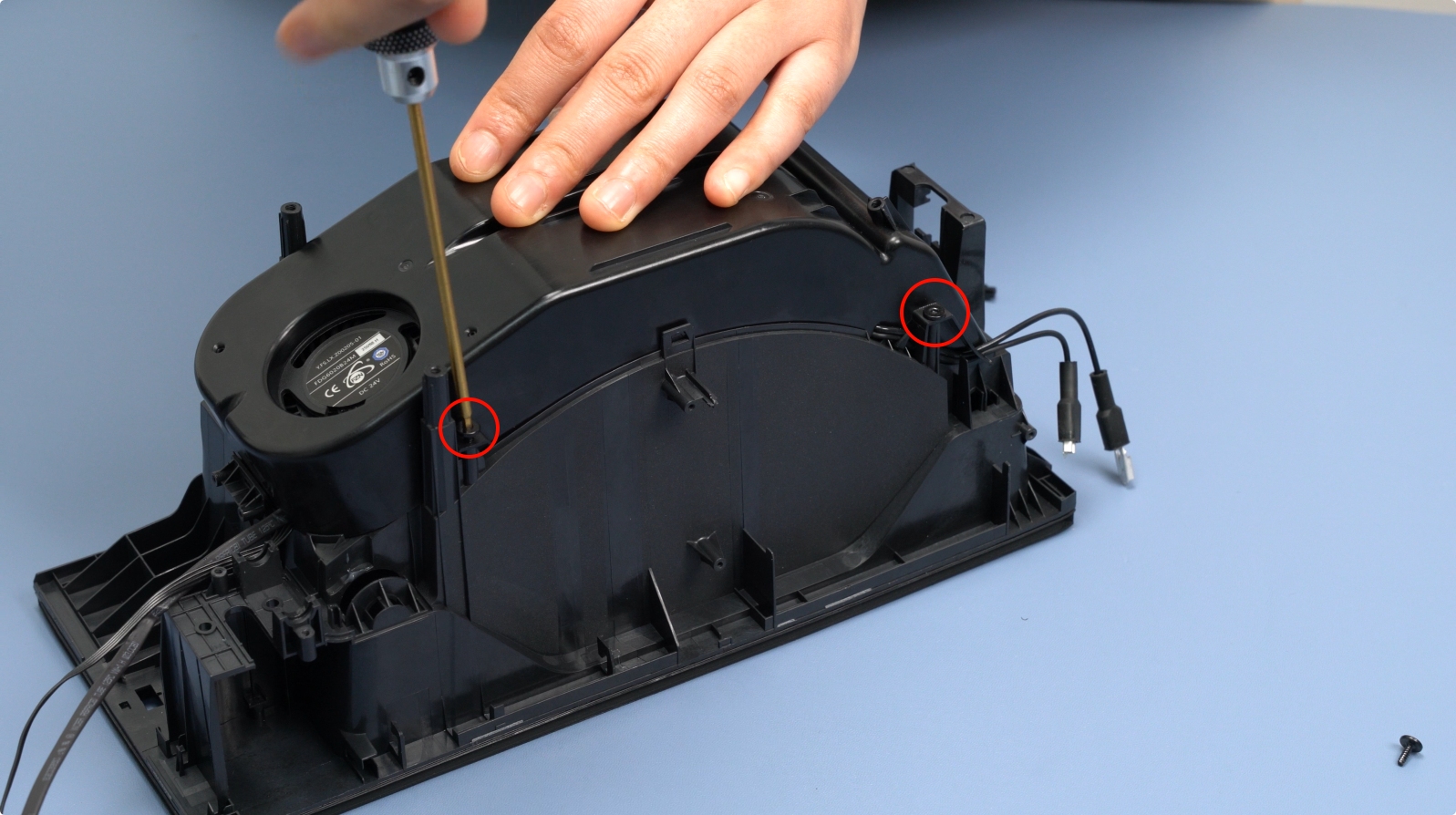
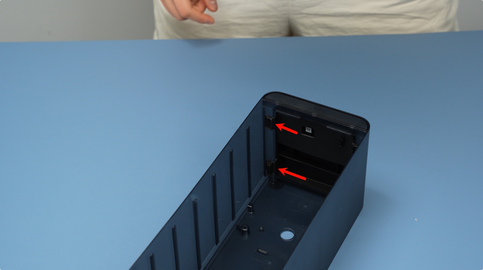
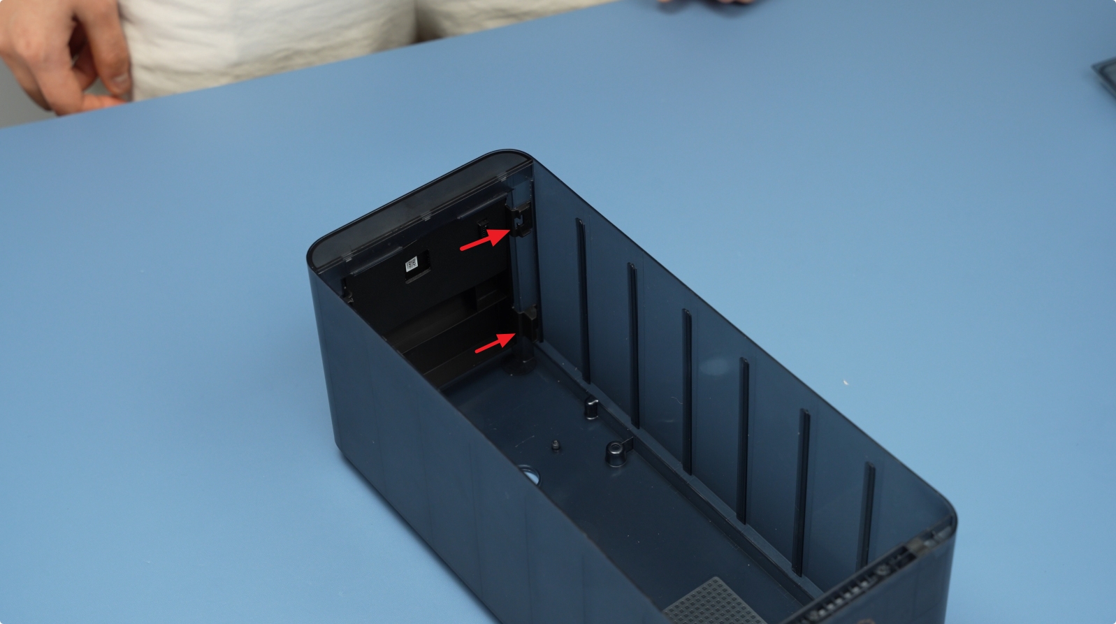
Remove the two bottom screws (BT3×8).
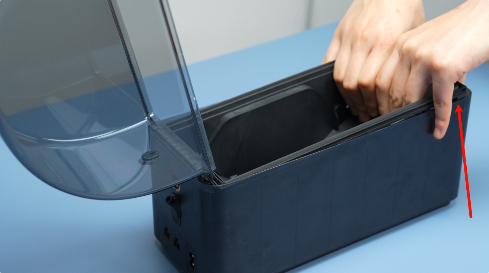
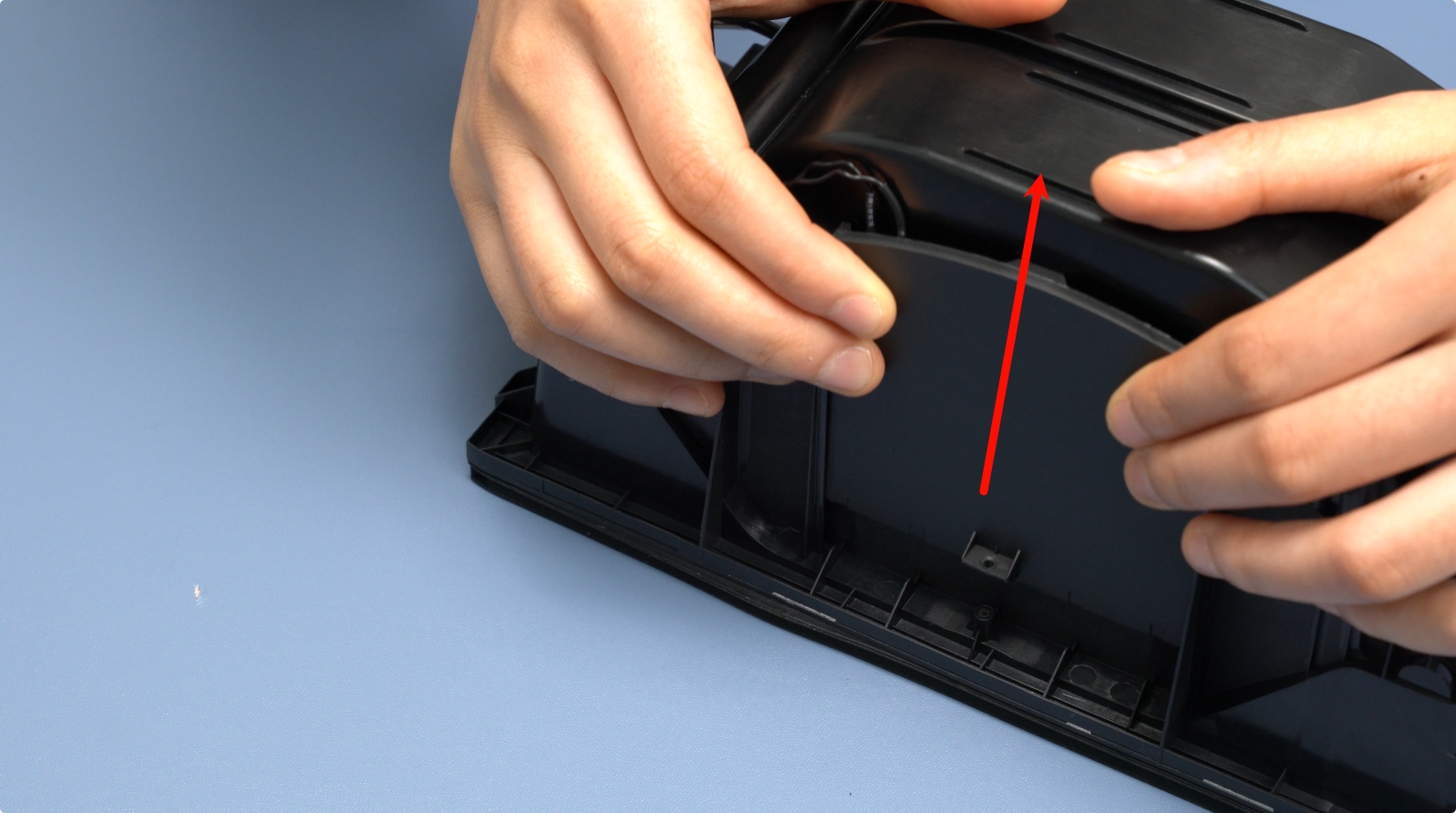
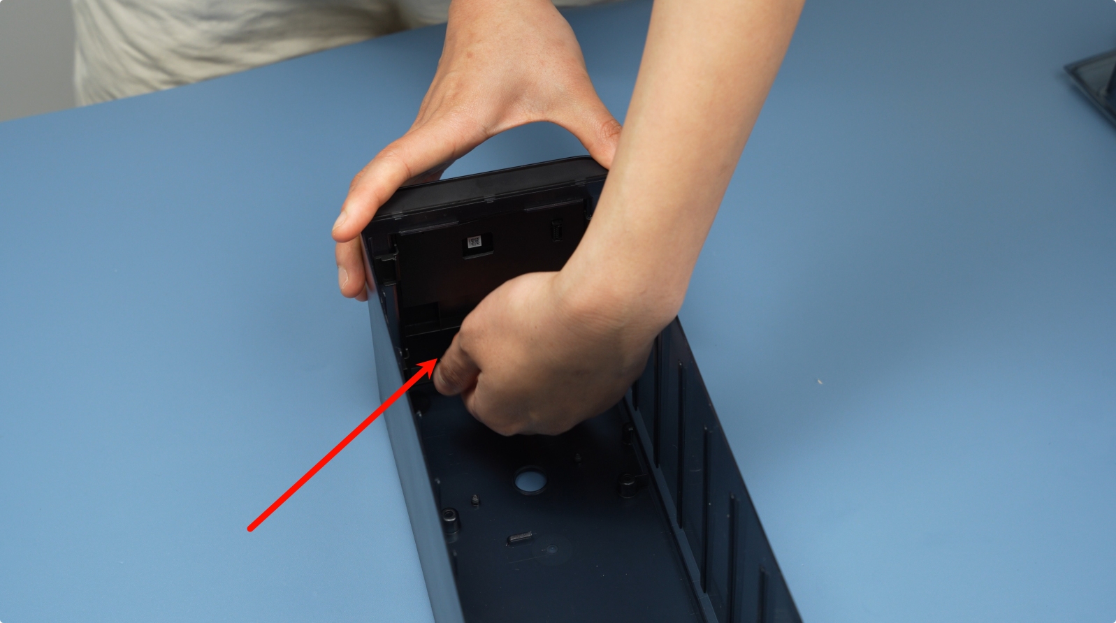
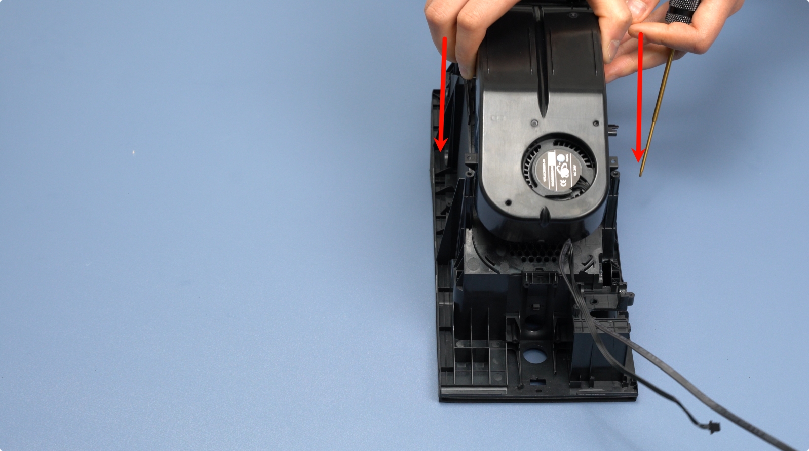
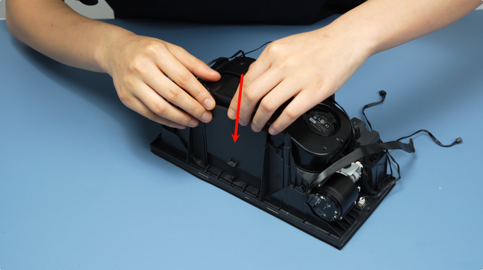
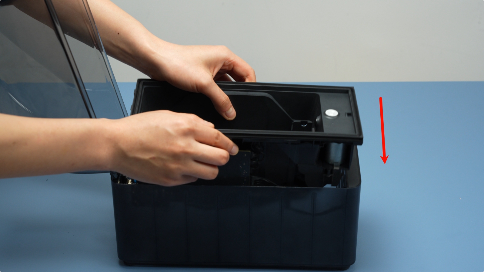
Lift the main frame assembly slowly upward.
 |
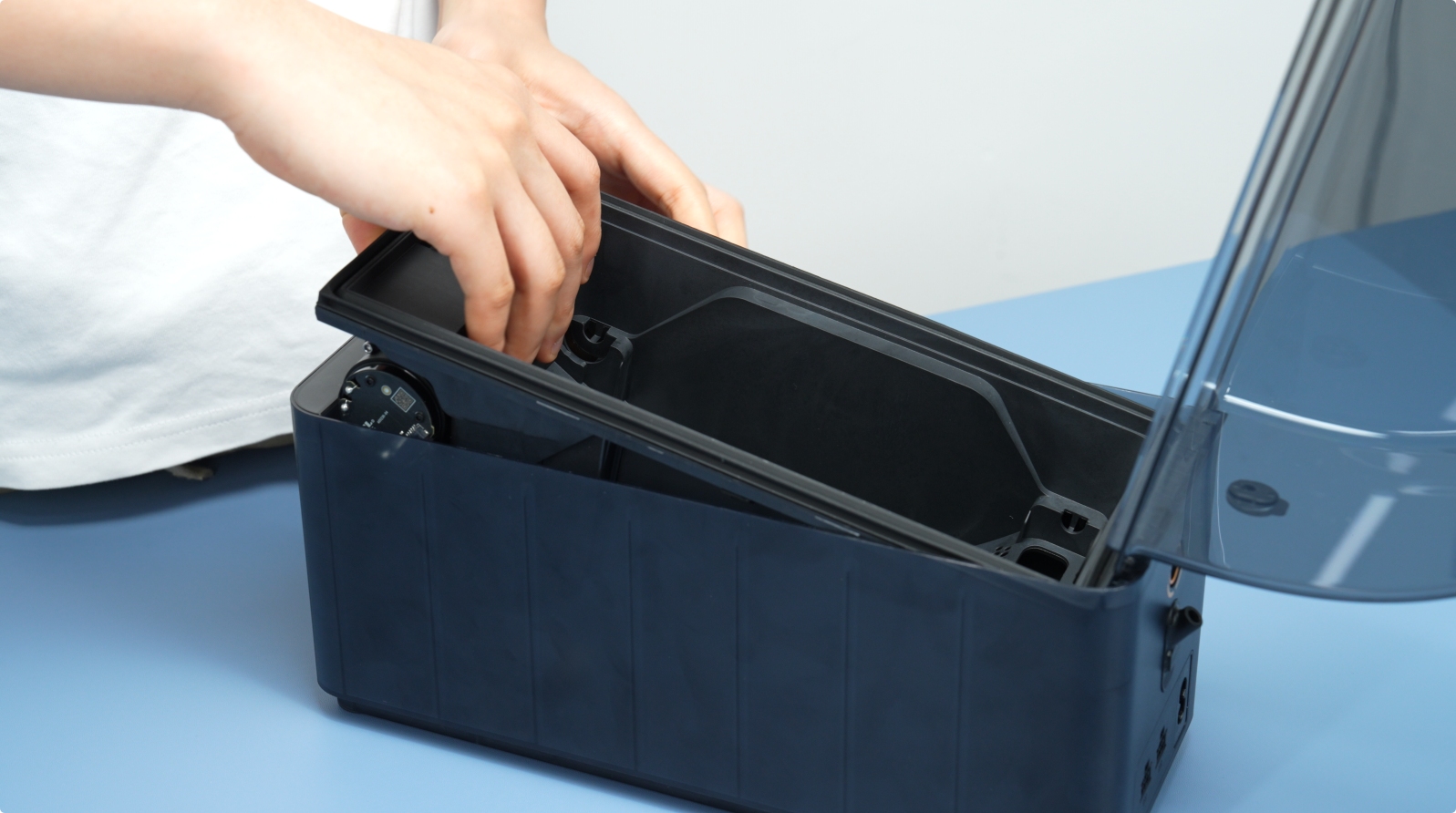 |
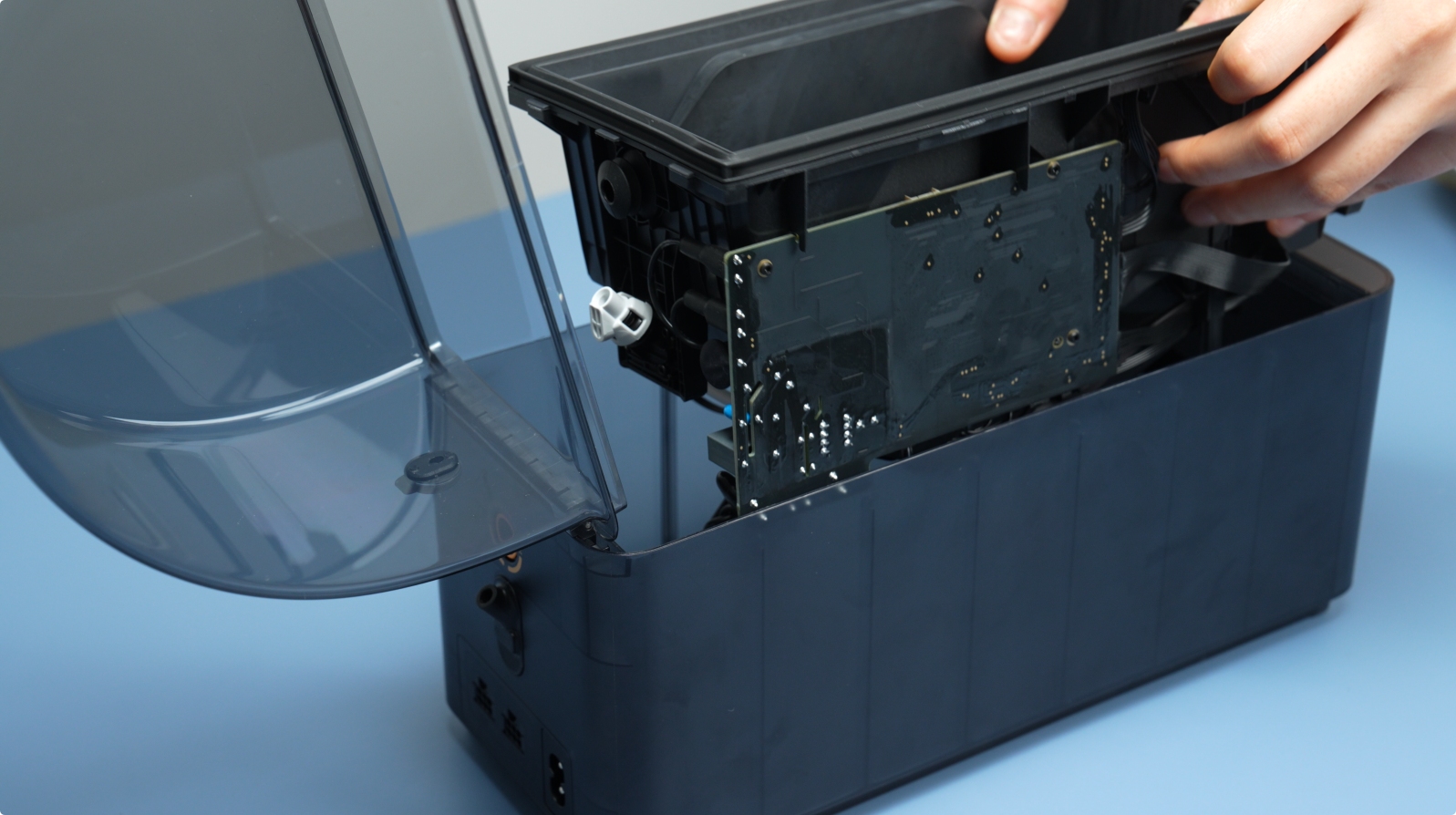
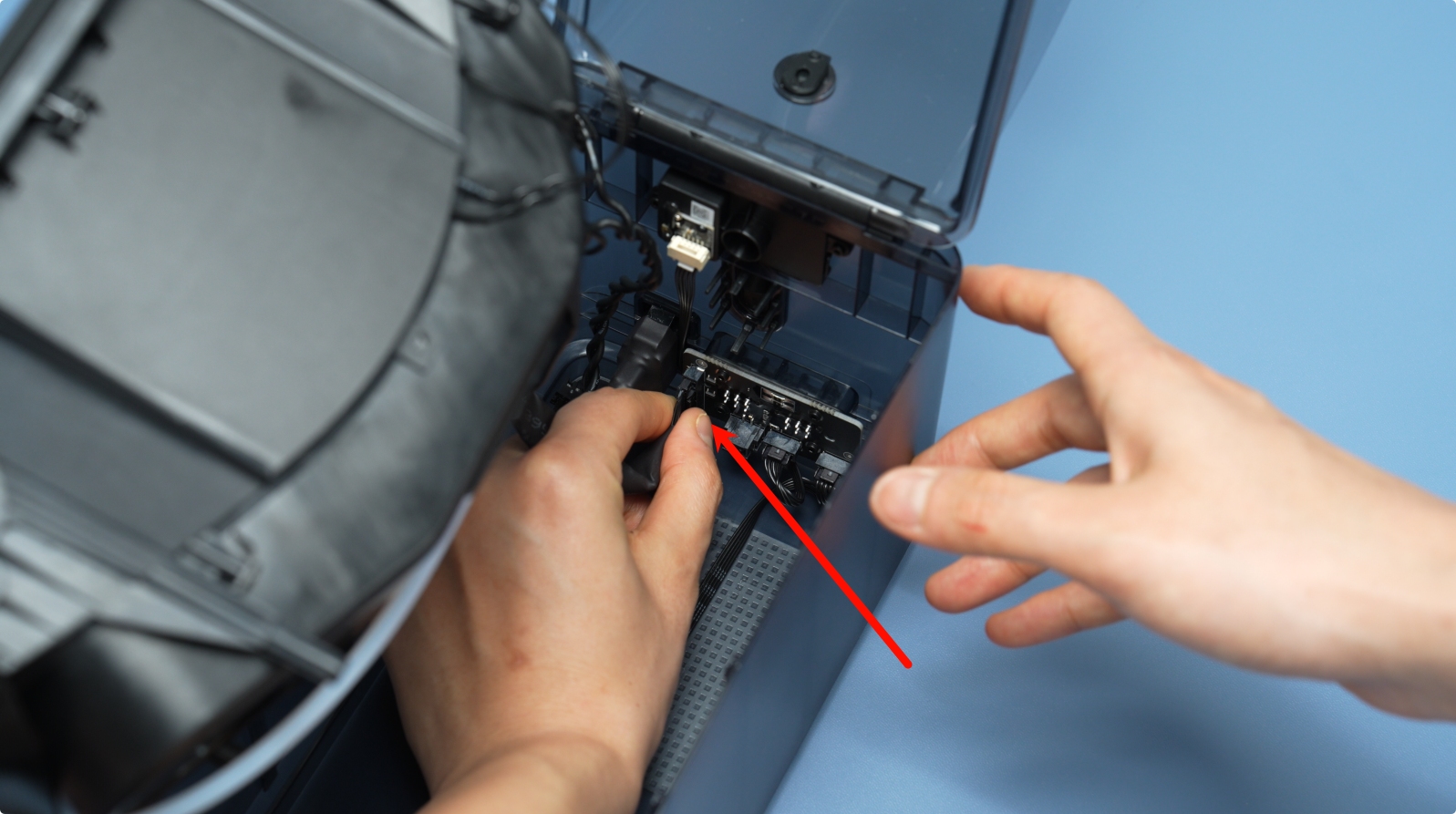
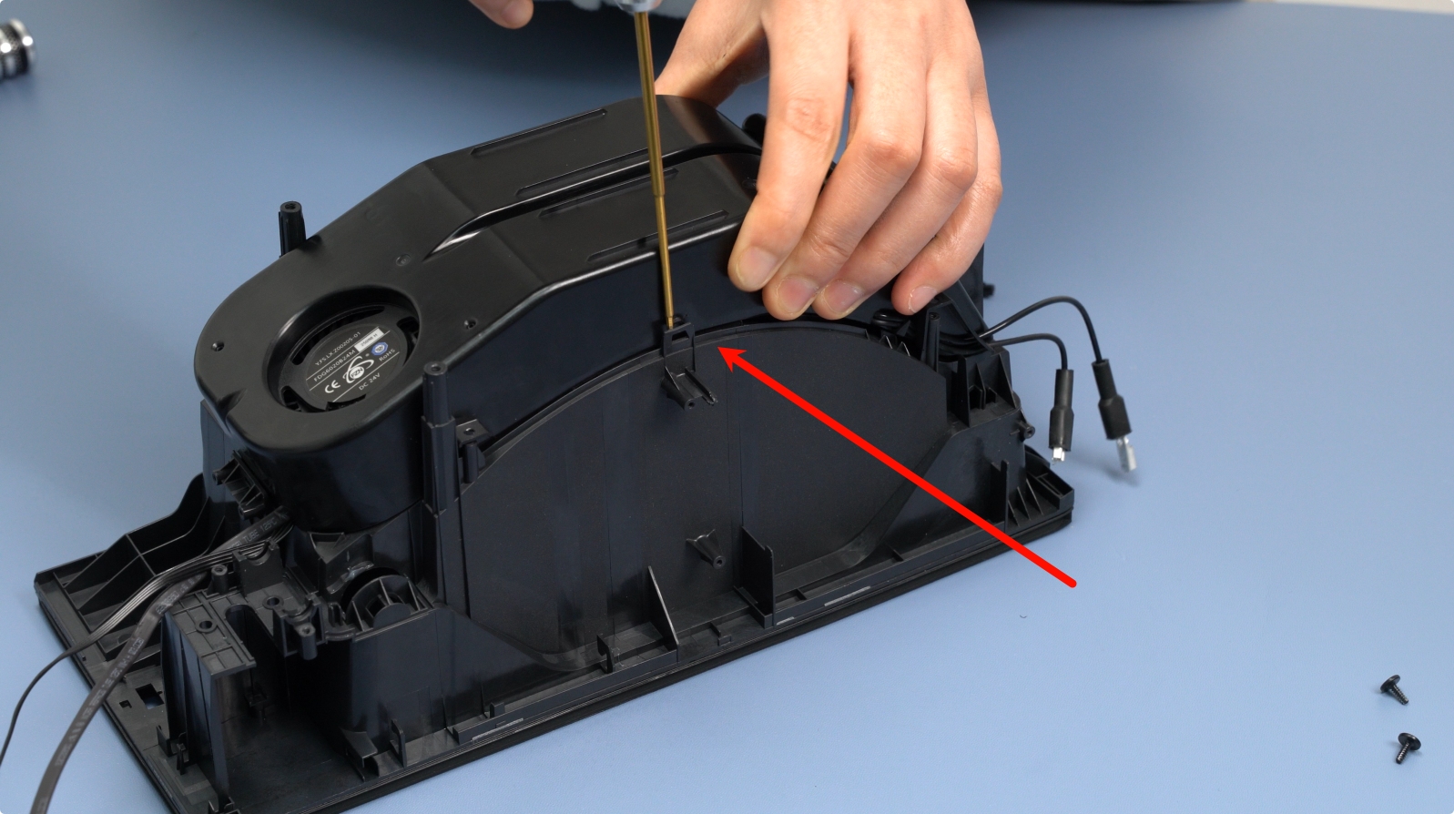
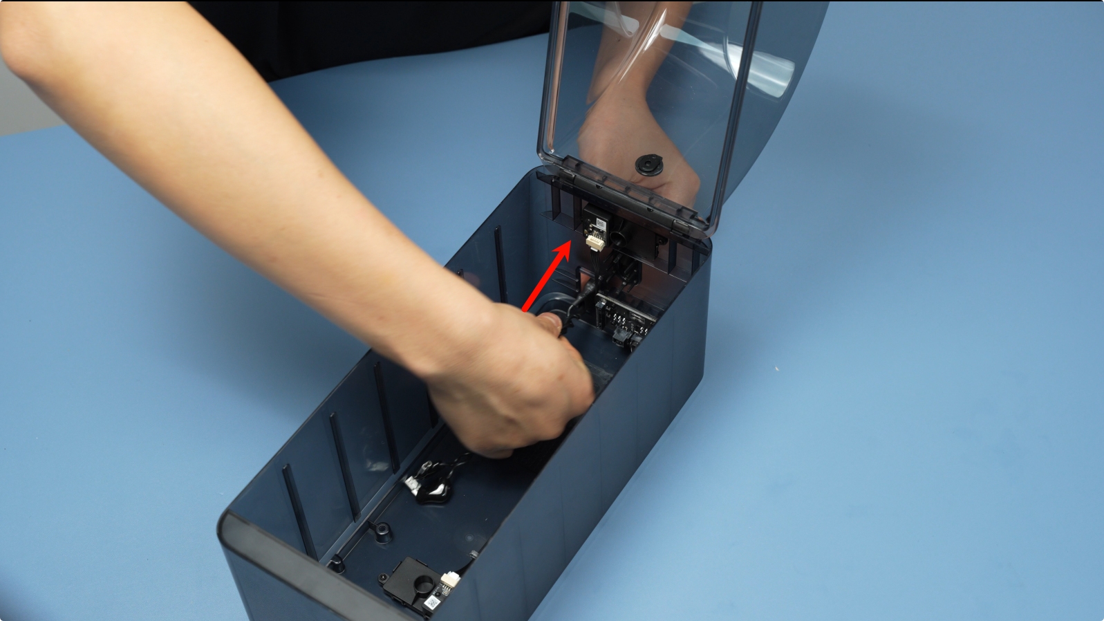
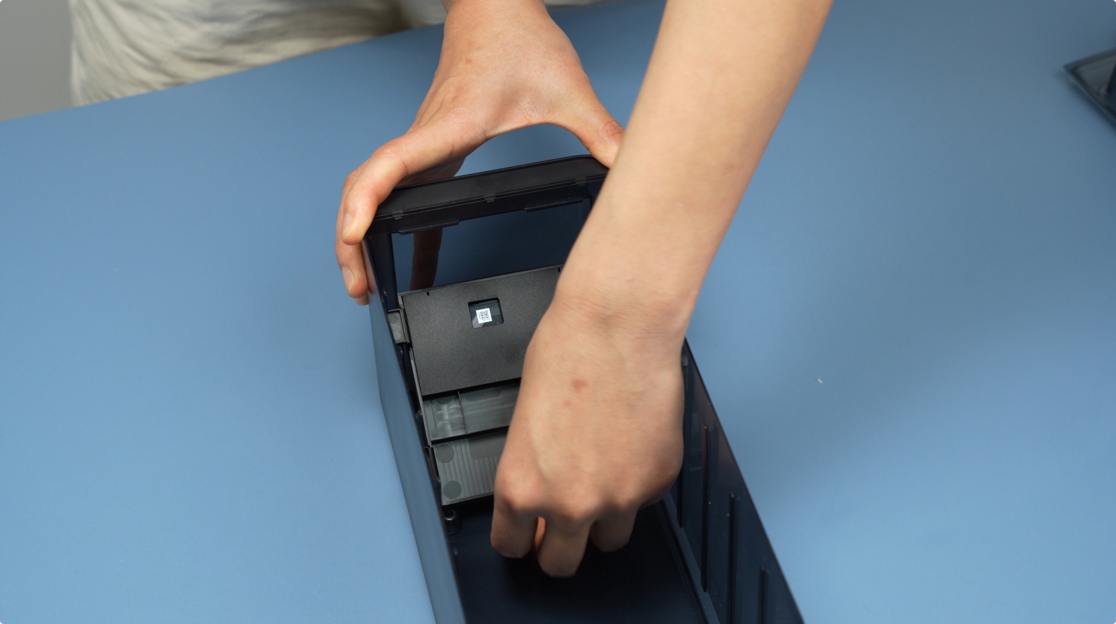
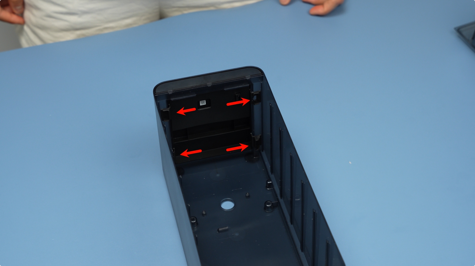
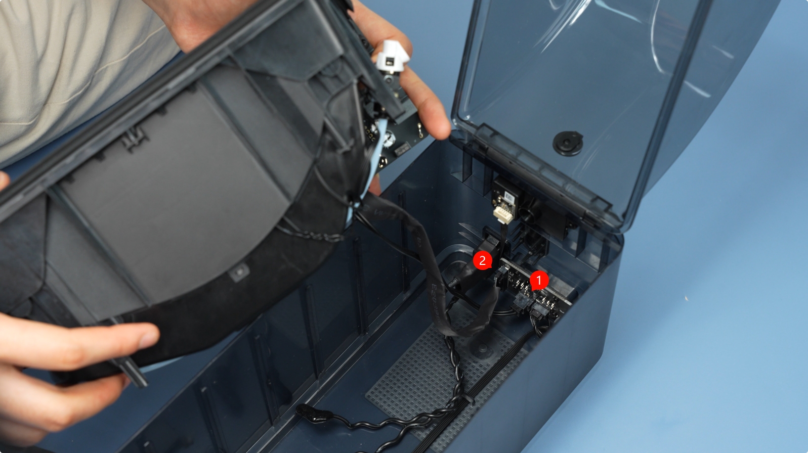
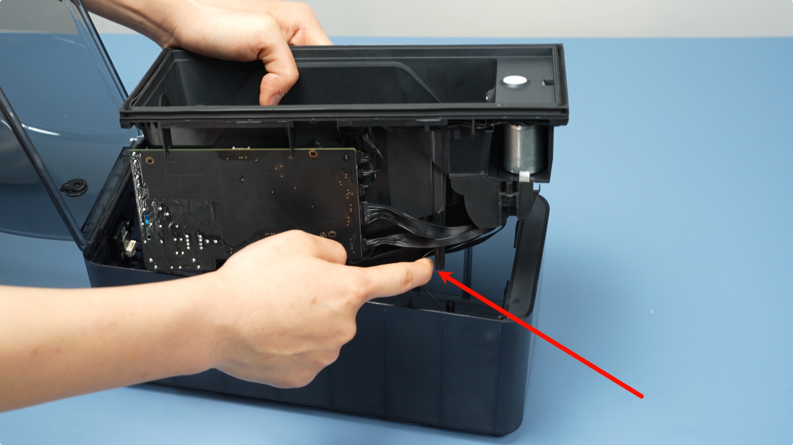
After opening the gap, lift the main frame assembly. Note: Cables are connected—avoid forceful operation.
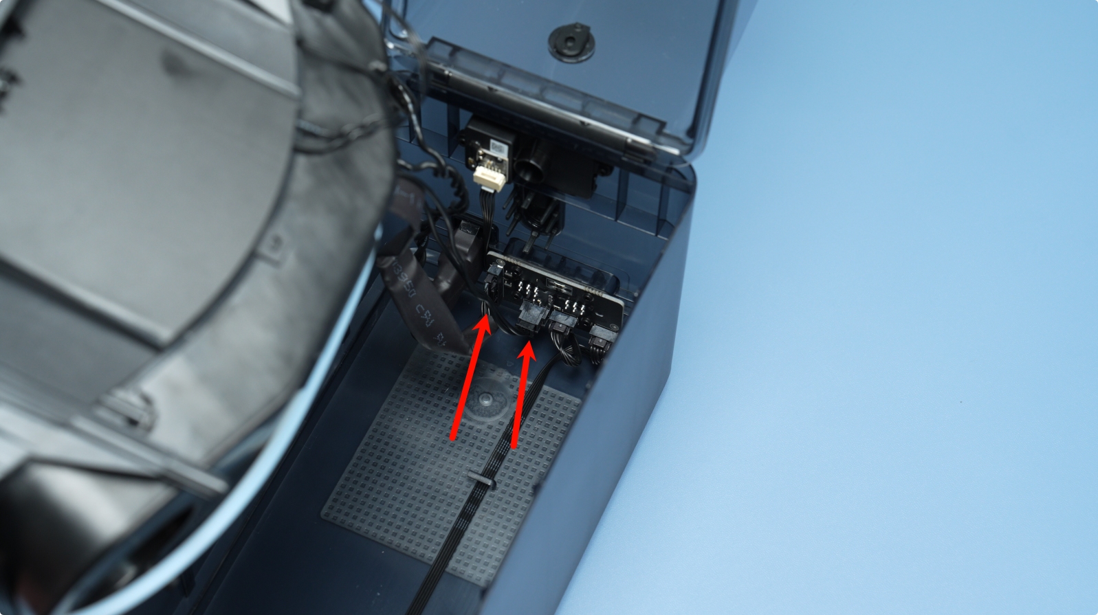
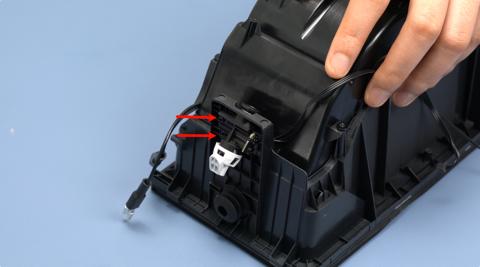
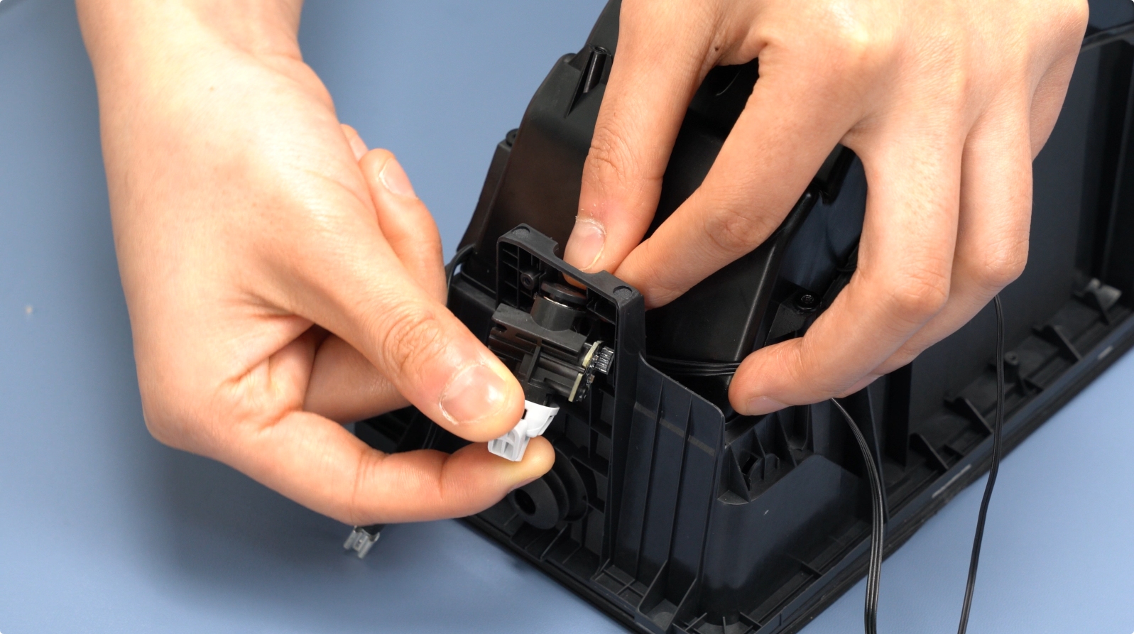
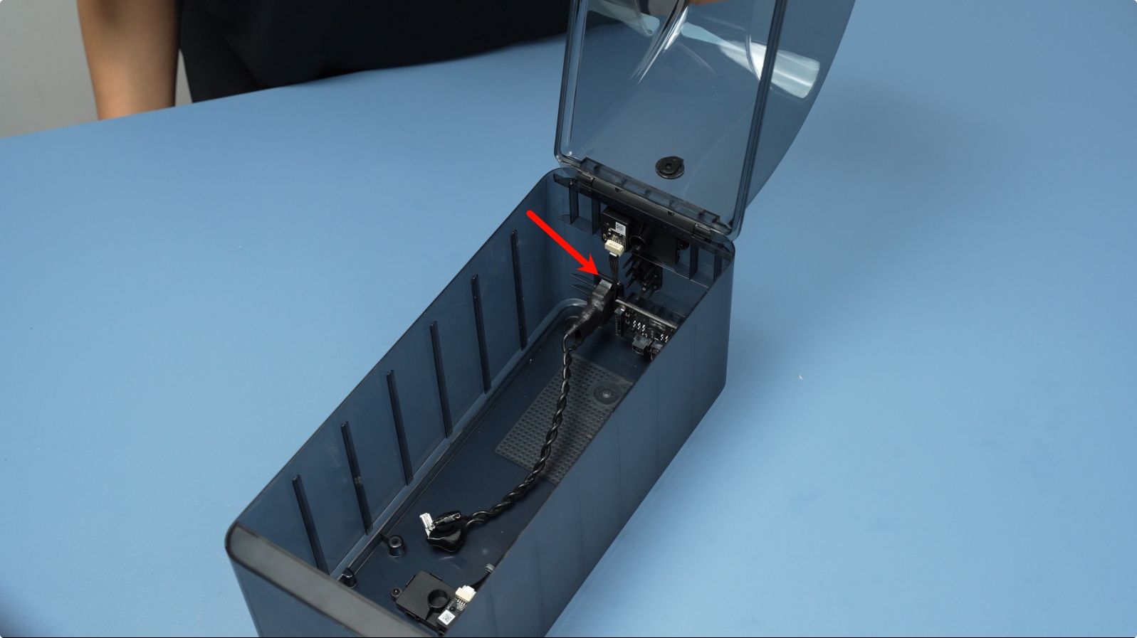
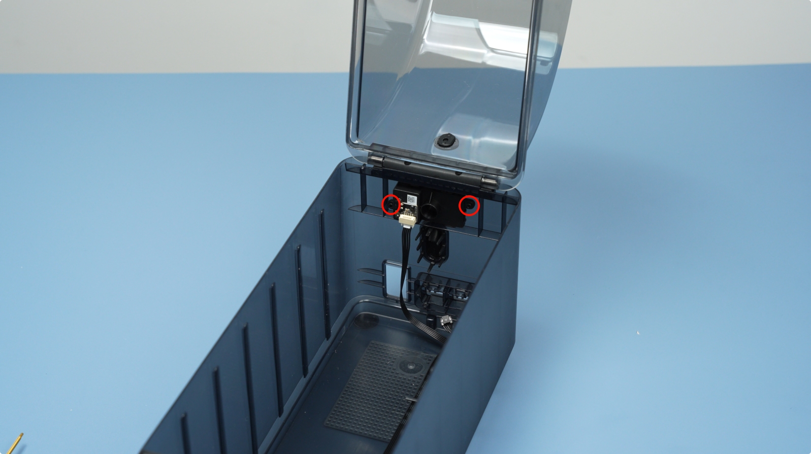
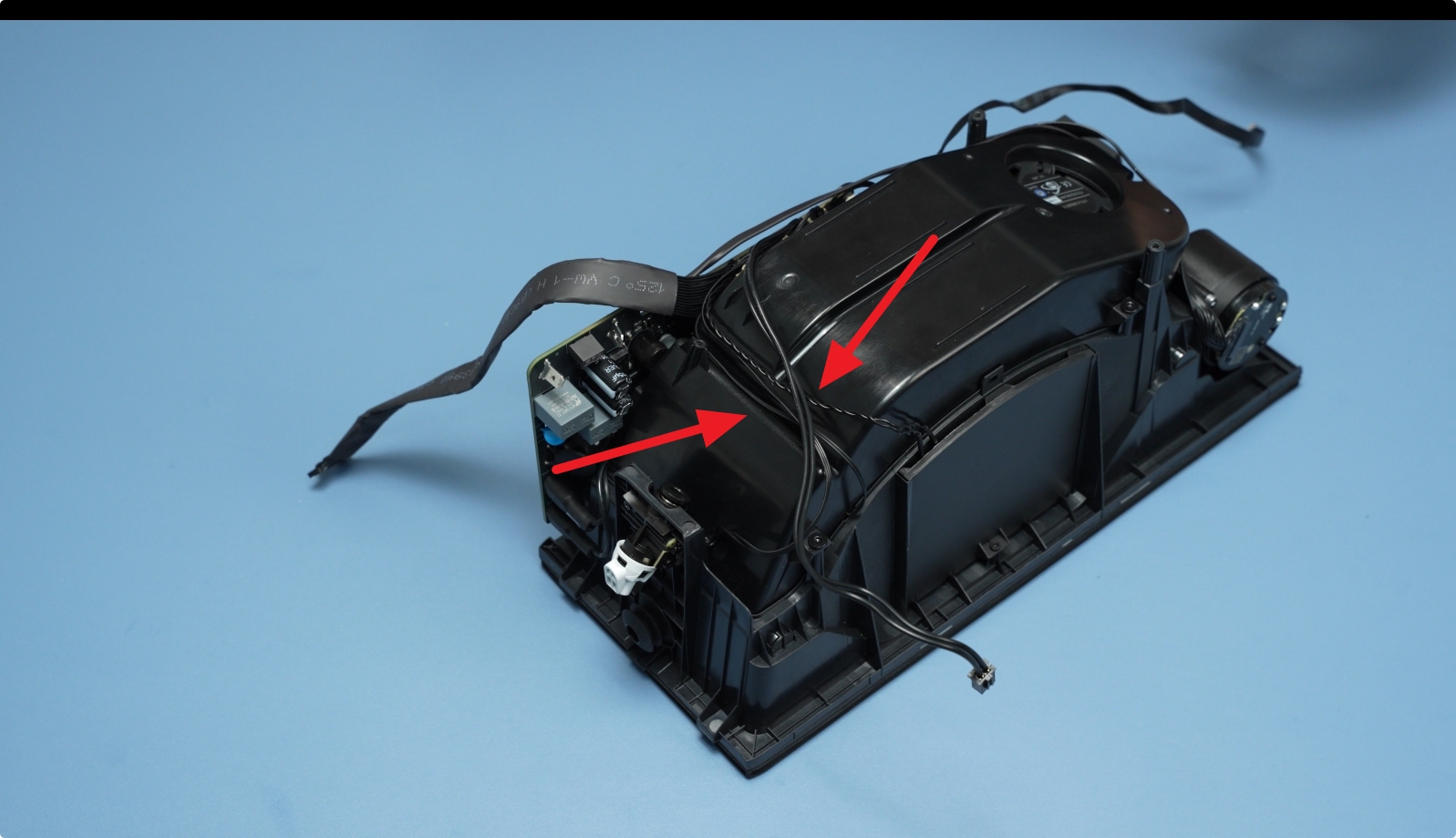
Unlock the connector latch and disconnect the front screen cable.

Next, disconnect the signal and power cables from the AMS HT Power Board.
 |
 |
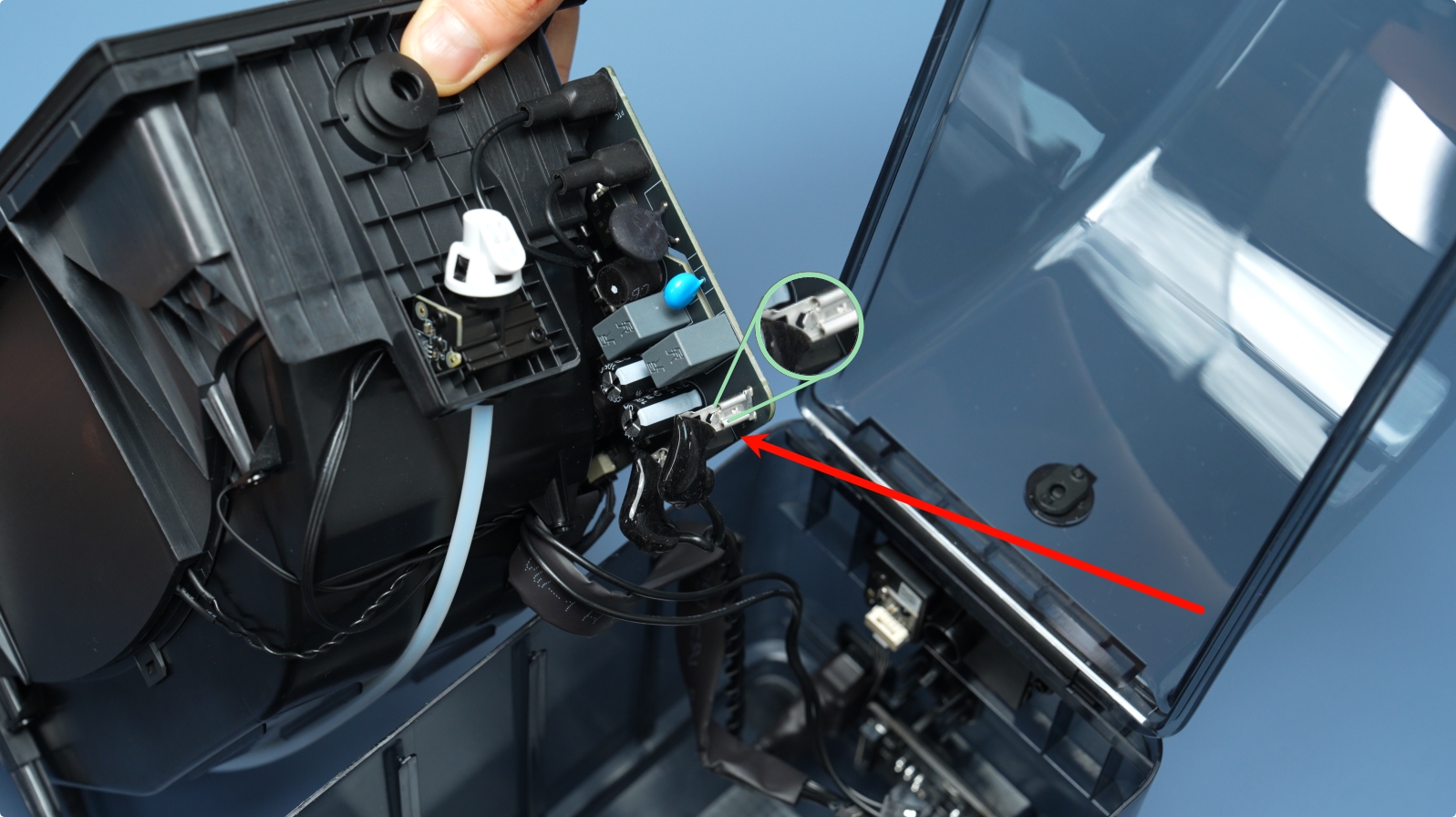
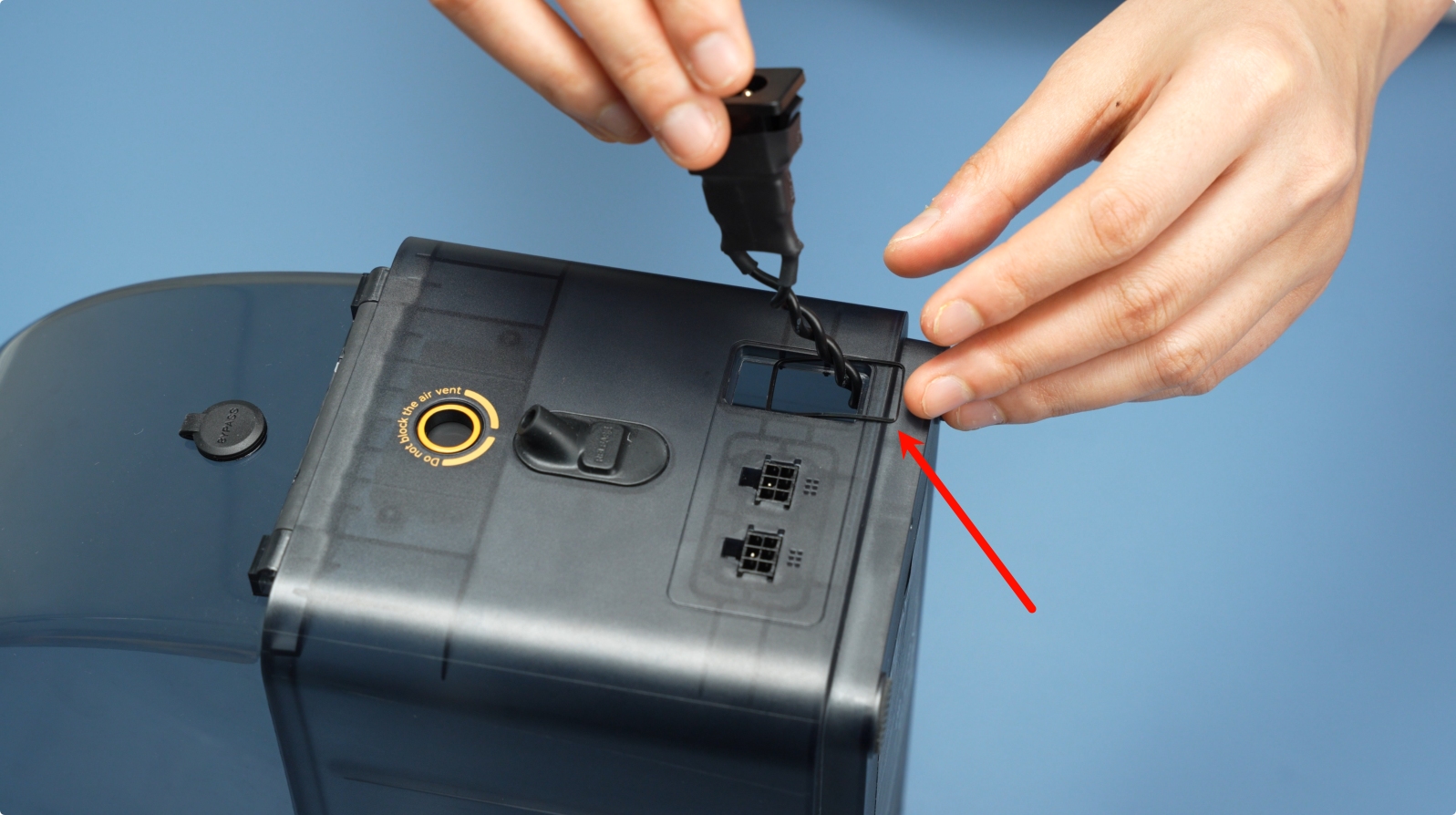
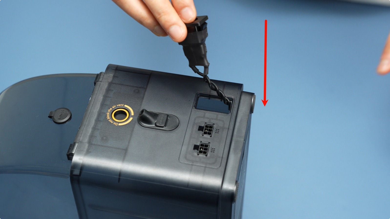
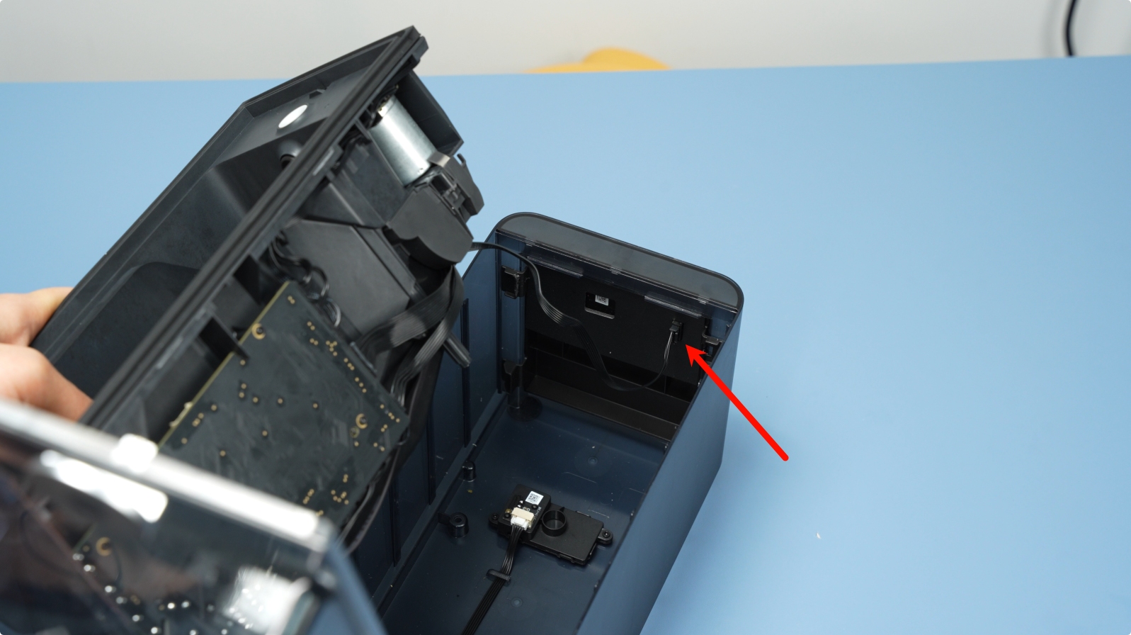
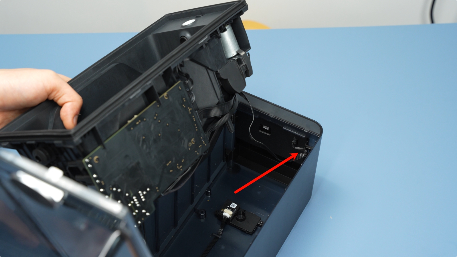
Remove the power socket-to-mainboard cable. Press the unlock latch and pull out the connector.
 |
 |
¶ 3. Remove the AMS HT Mainboard
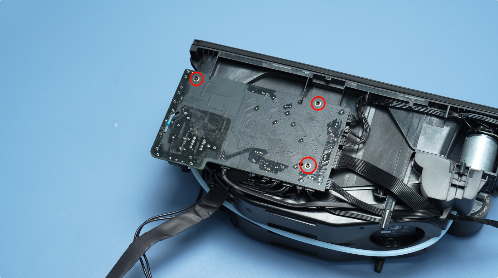
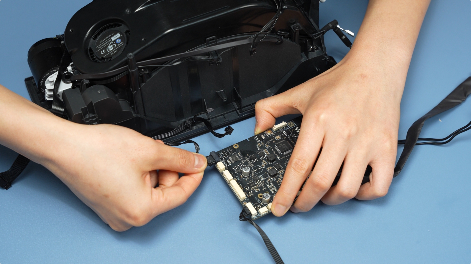
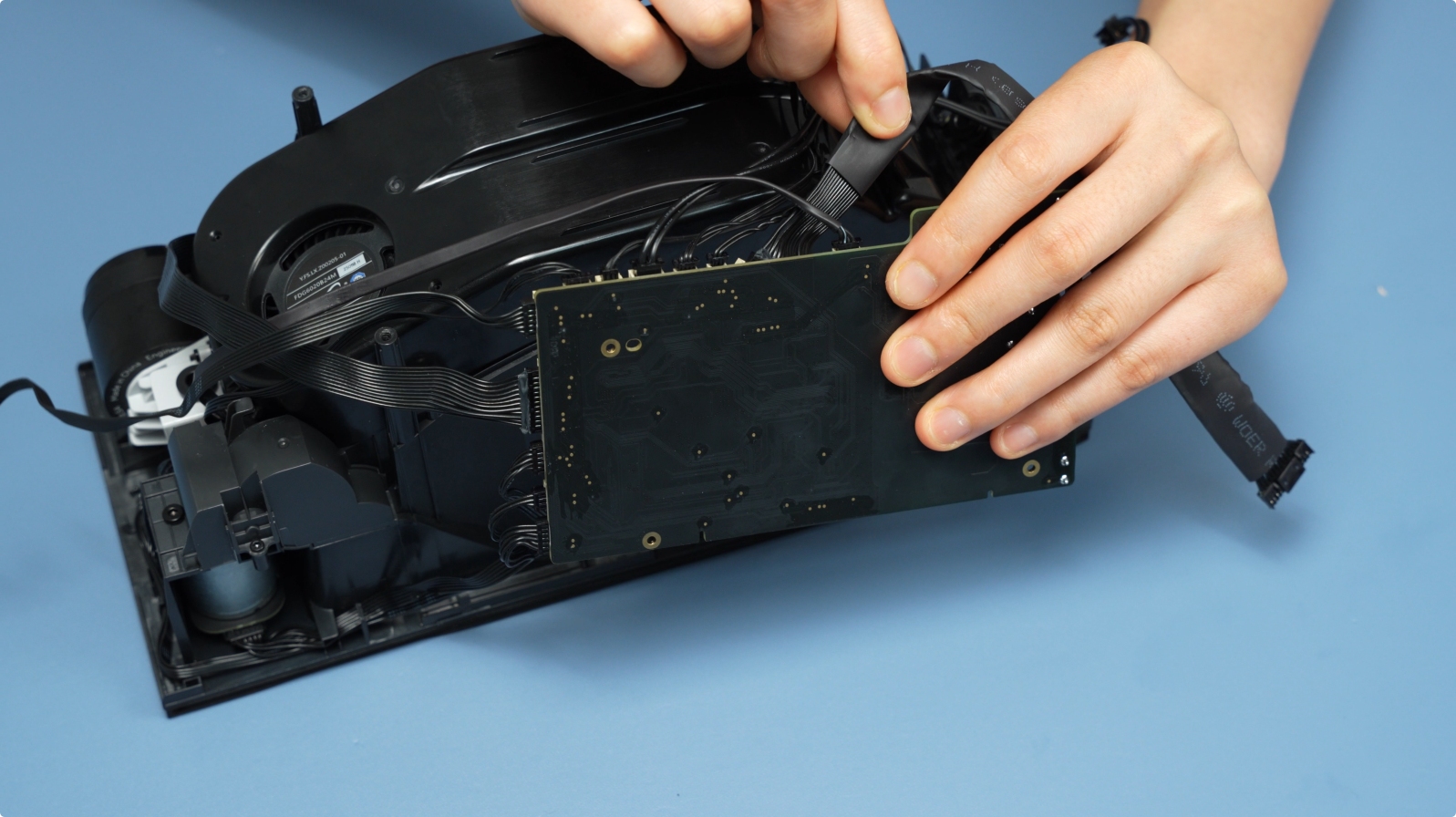
Loosen the three mainboard screws (BT2×5) and slide the mainboard out of its slot.
 |
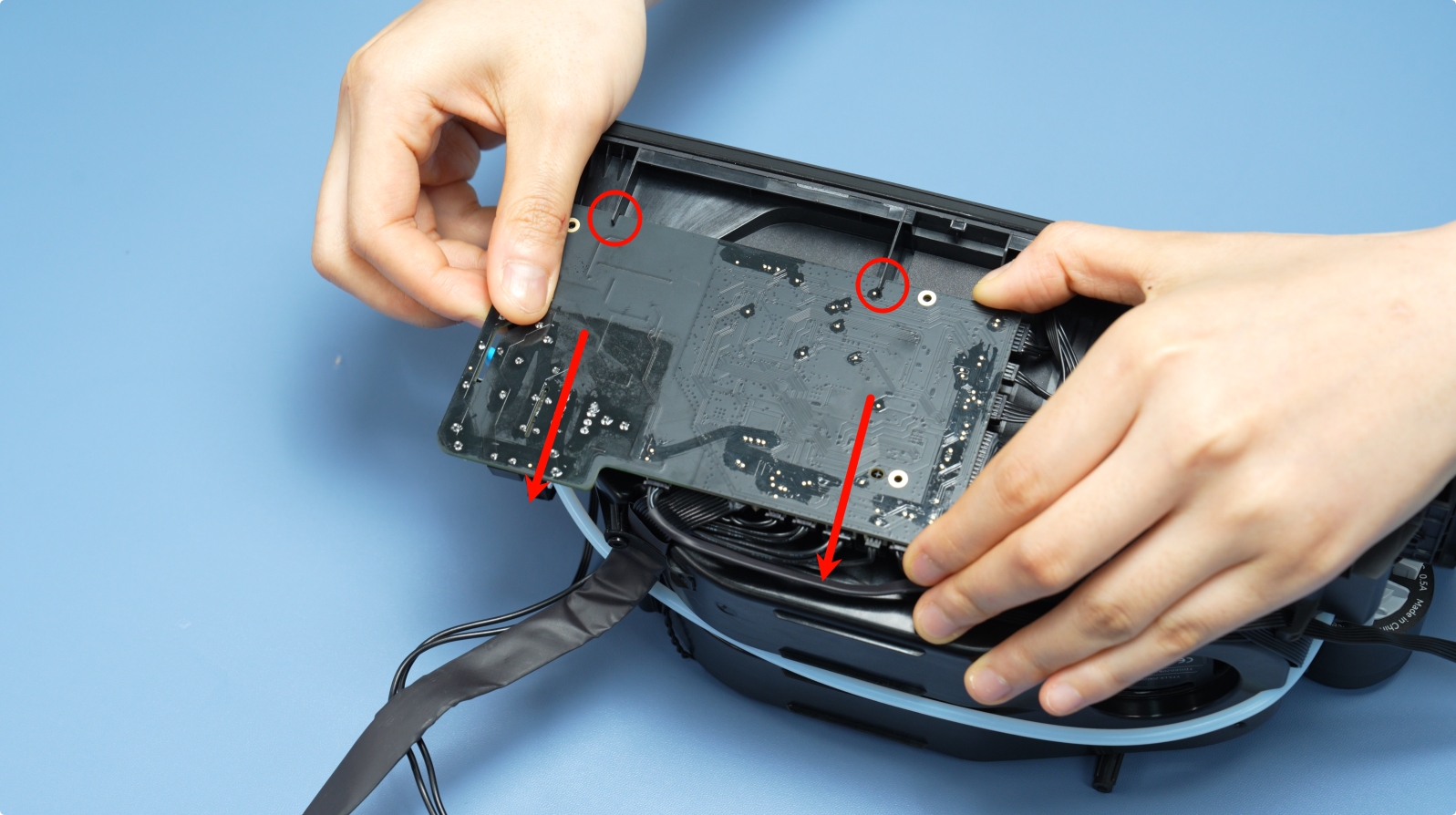 |
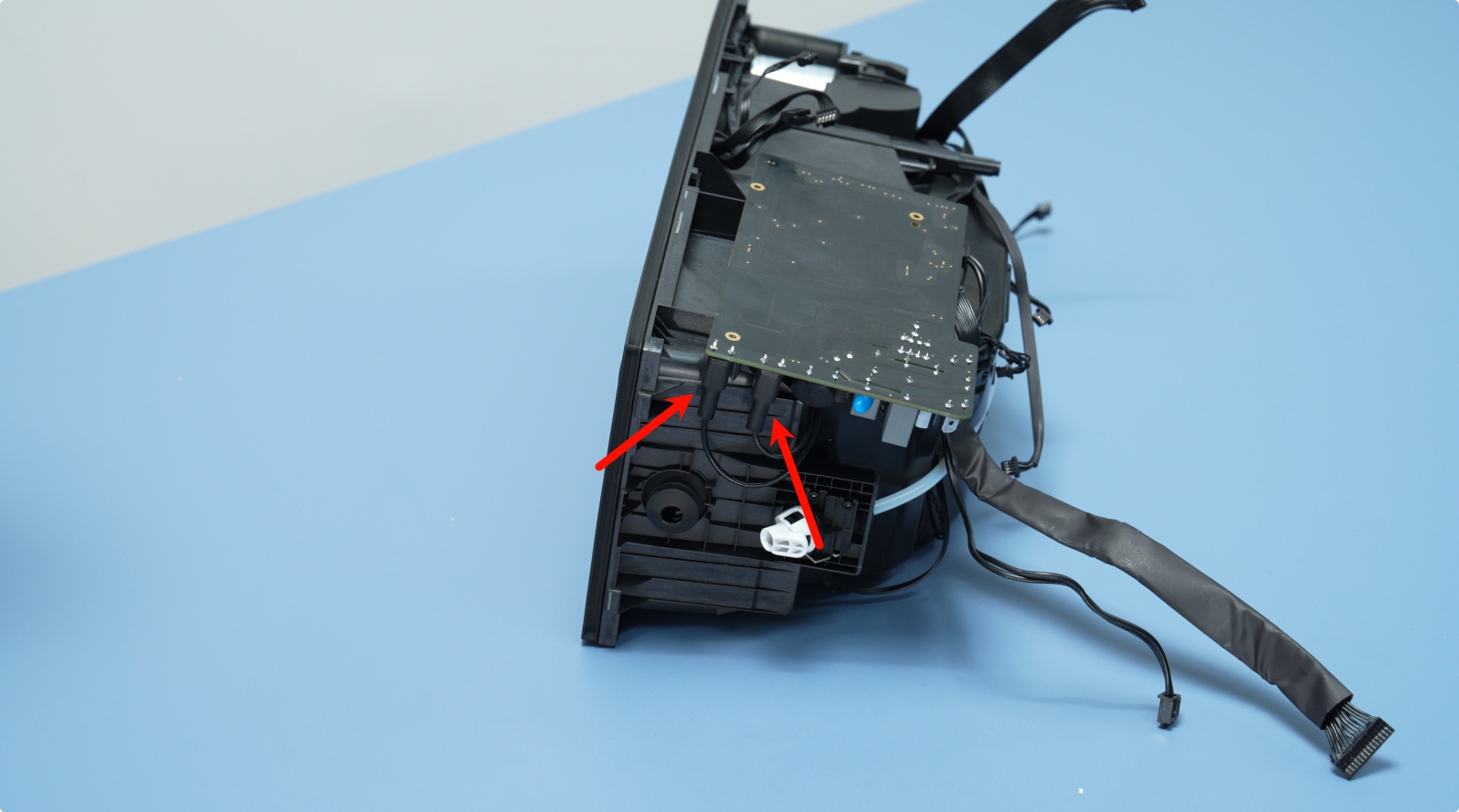
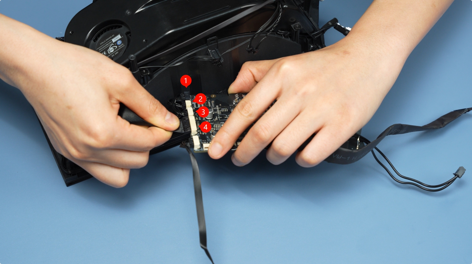
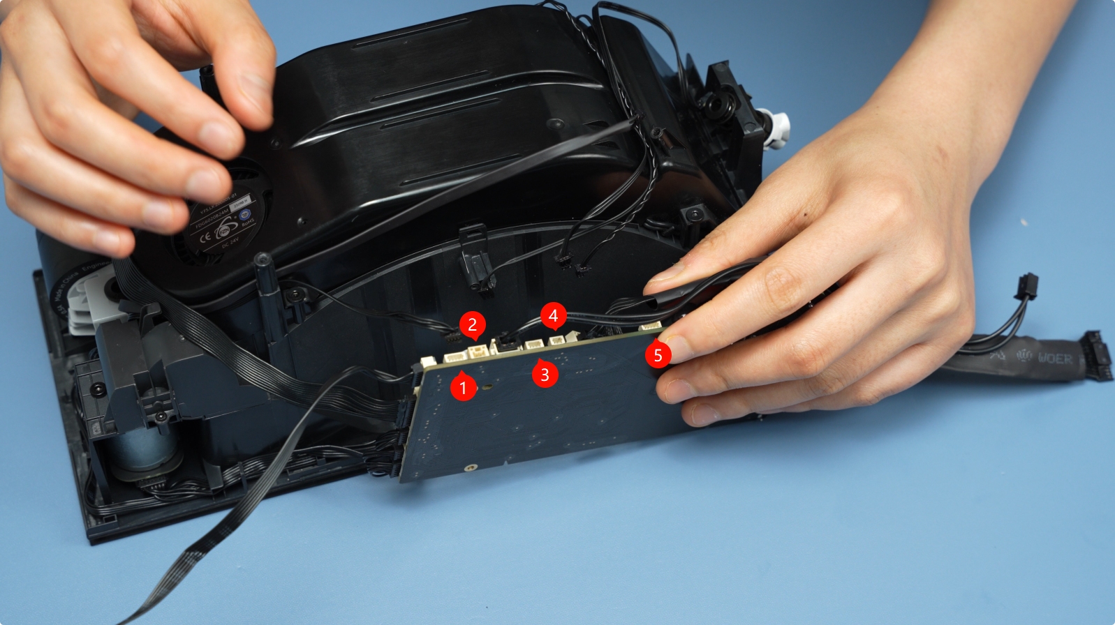
Disconnect the four cables from the mainboard in order.

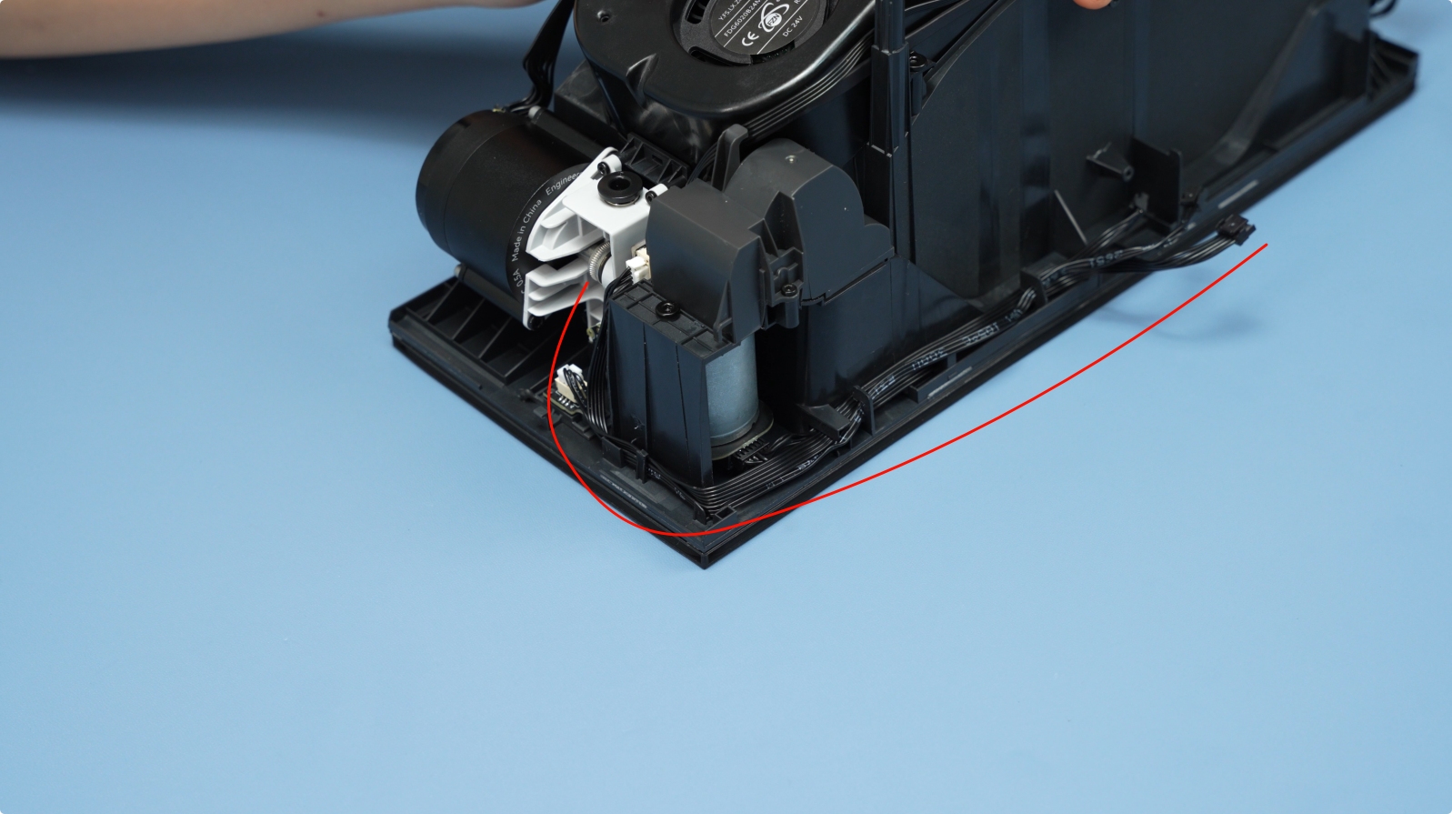
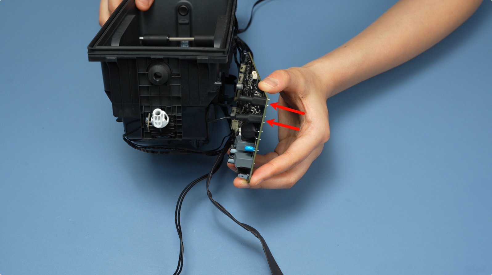
Remove the five cables at the bottom.

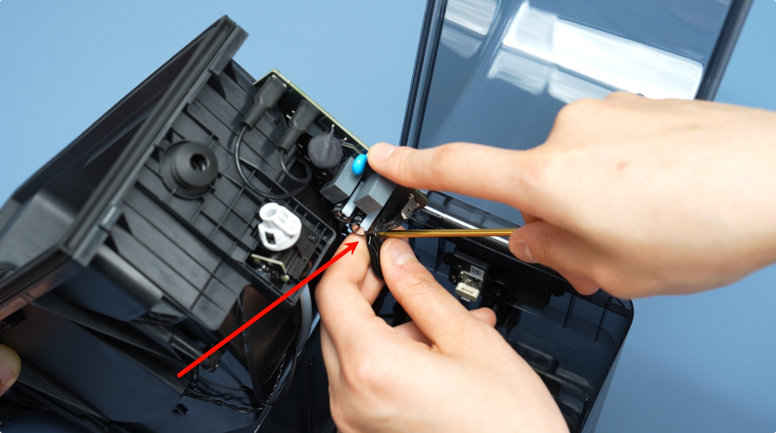
Disconnect the heater cable by first removing the insulation sleeve, pressing the unlock latch, and then gently pulling out the cable.
 |
 |
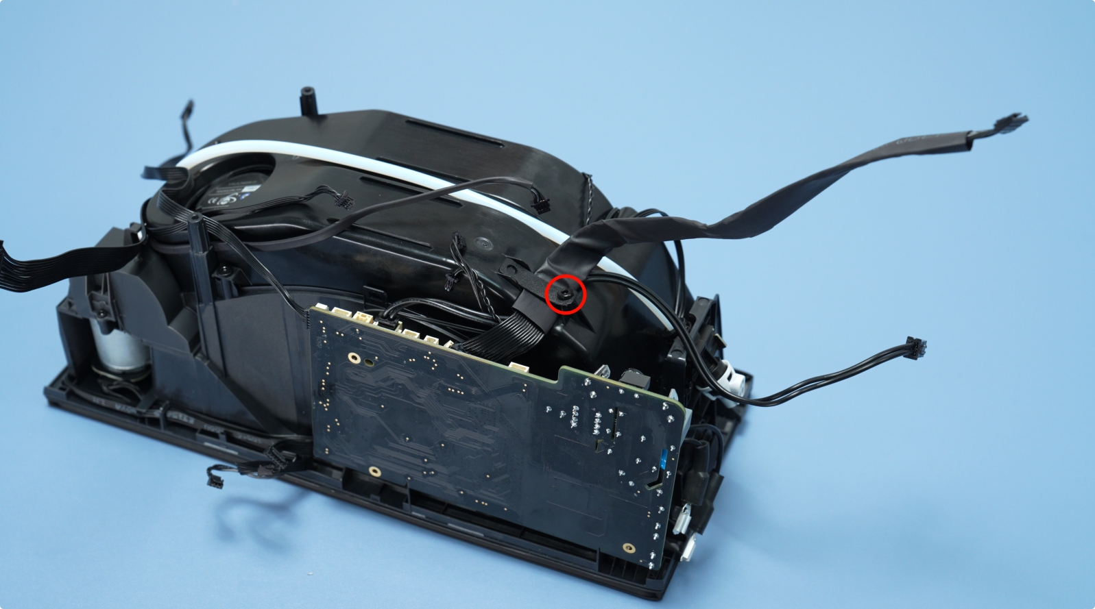
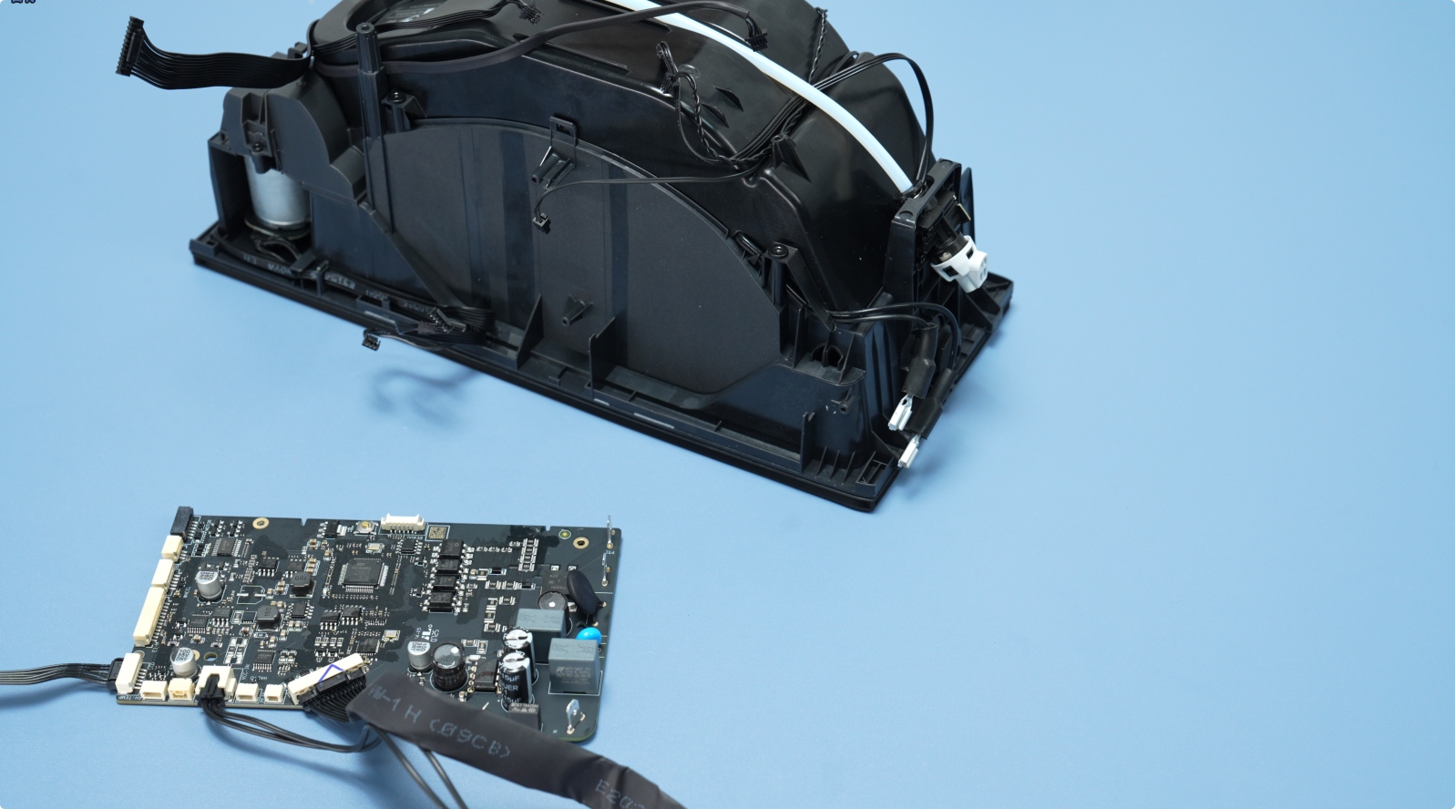
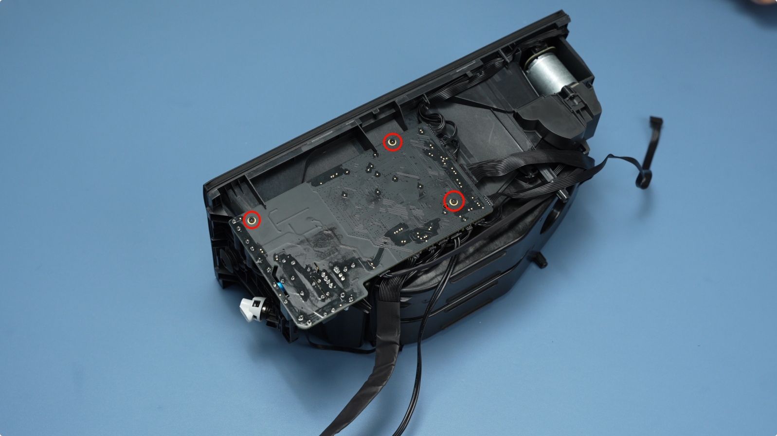
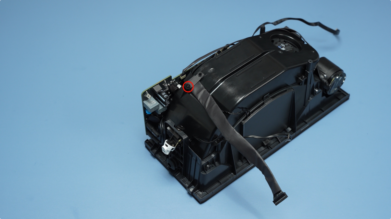
Remove the retainer screw (BT3×5) and take out the mainboard.
 |
 |
¶ 4. Remove the Feeder Unit
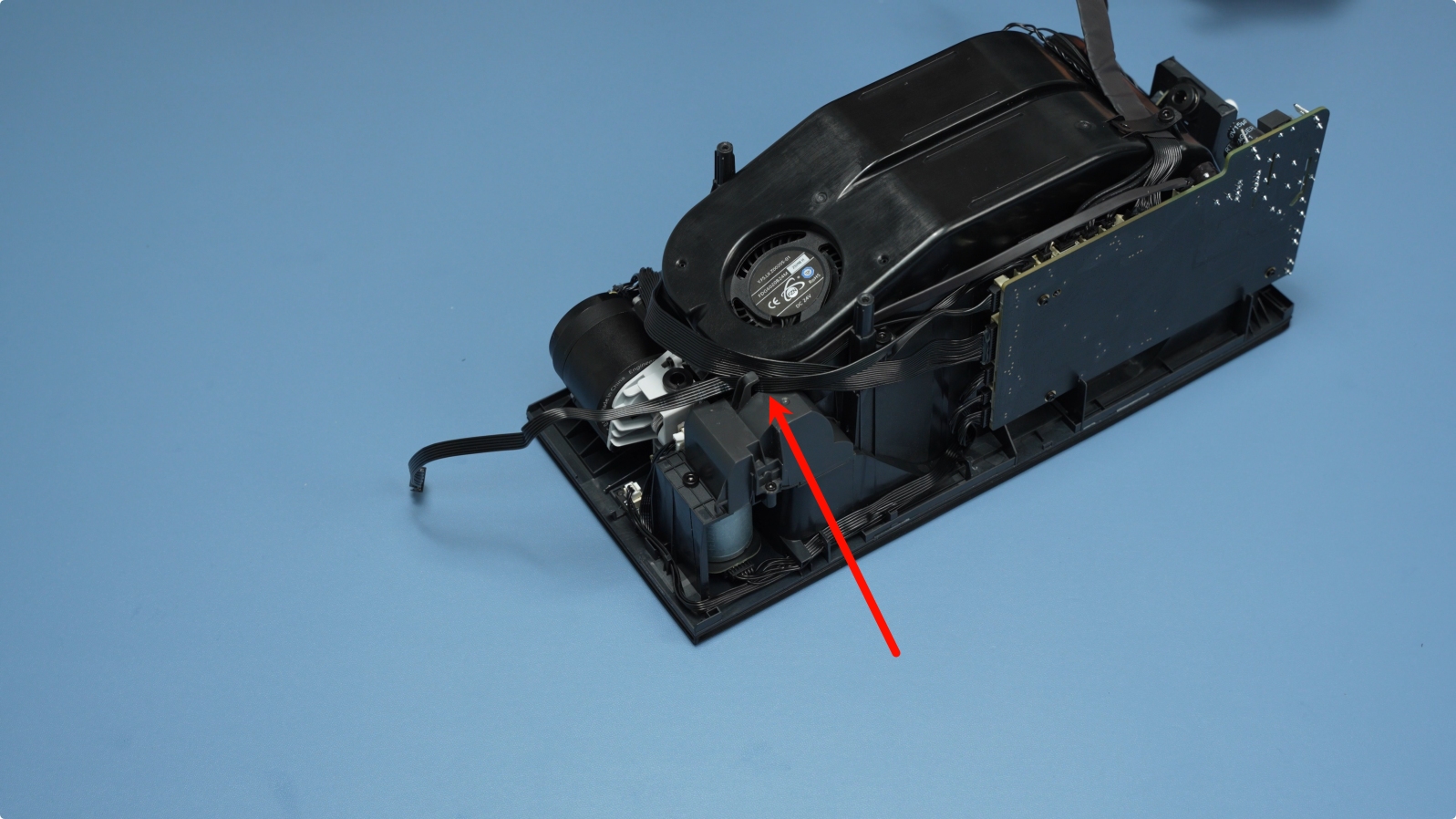
First, remove the PTFE tube between the feeder and the outlet.
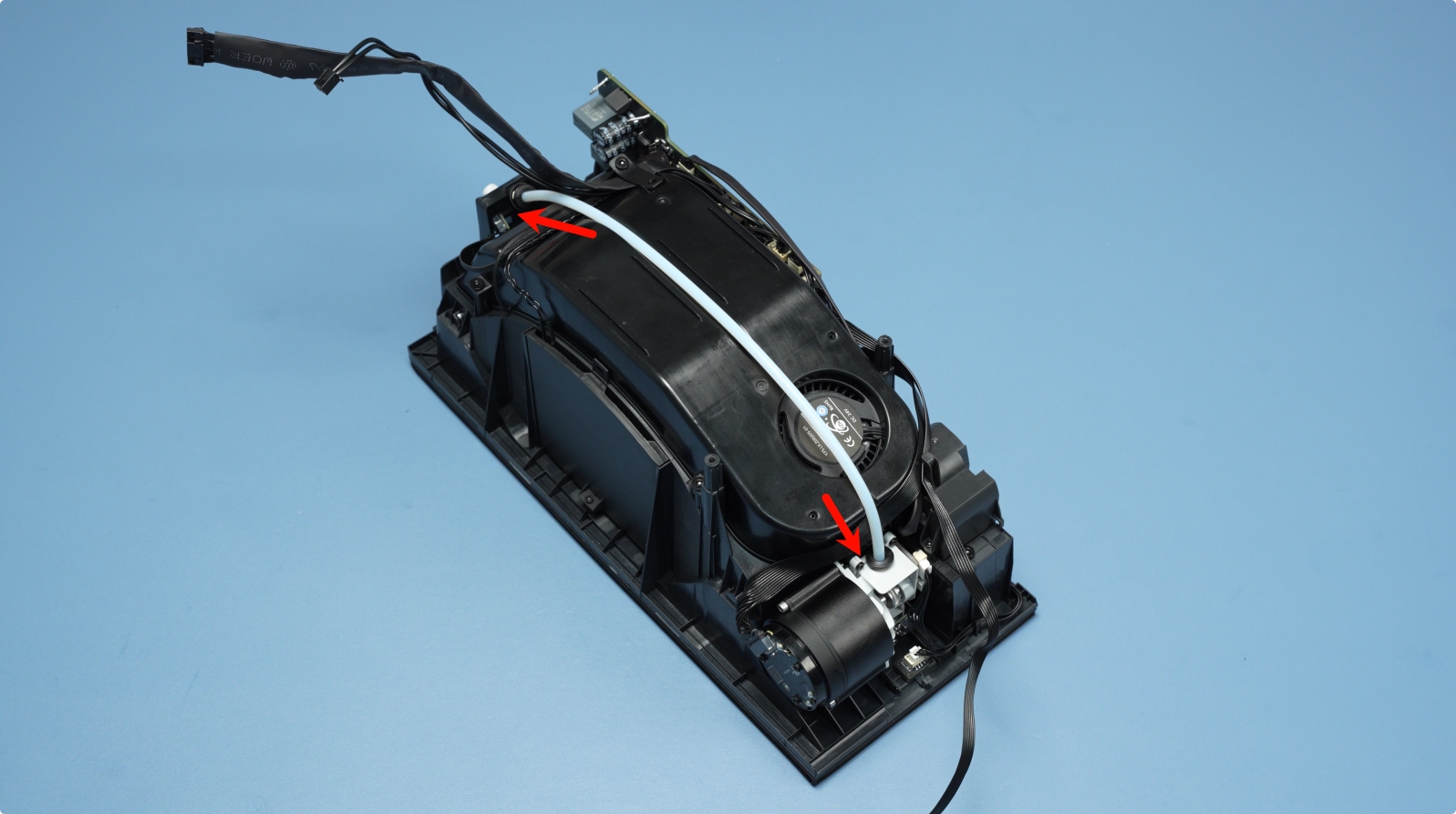
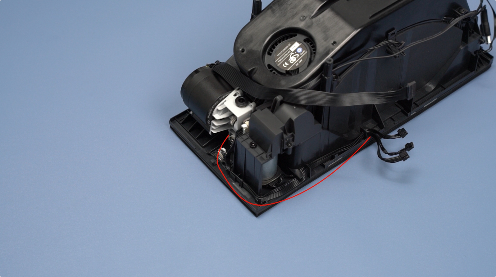
Remove the four feeder screws (BT2×8) and pull the feeder cables out of the cable channel.
 |
 |
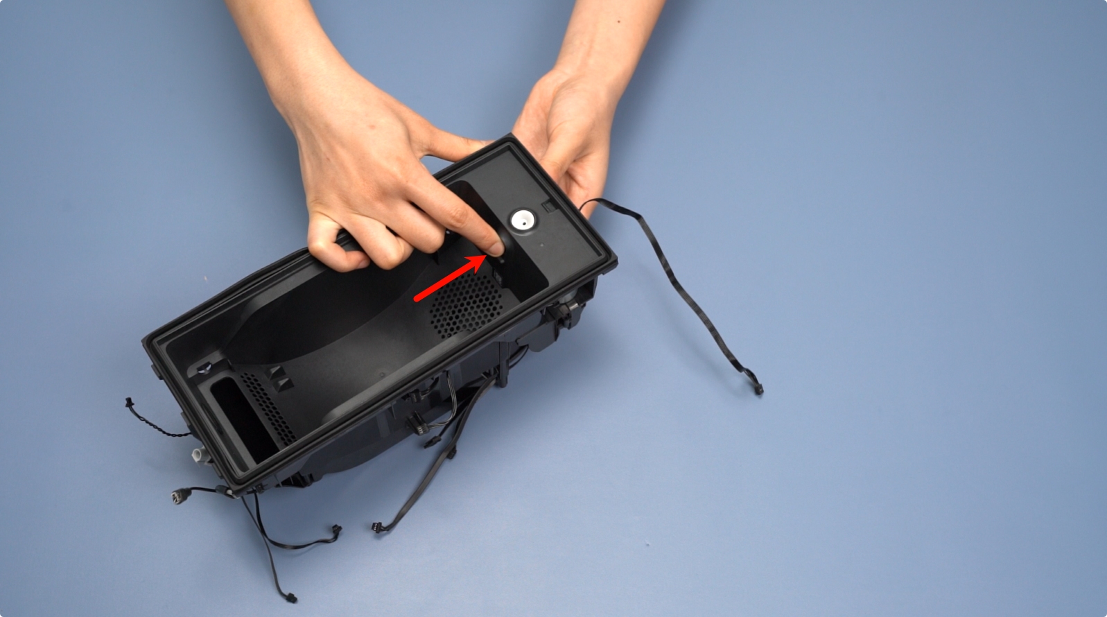
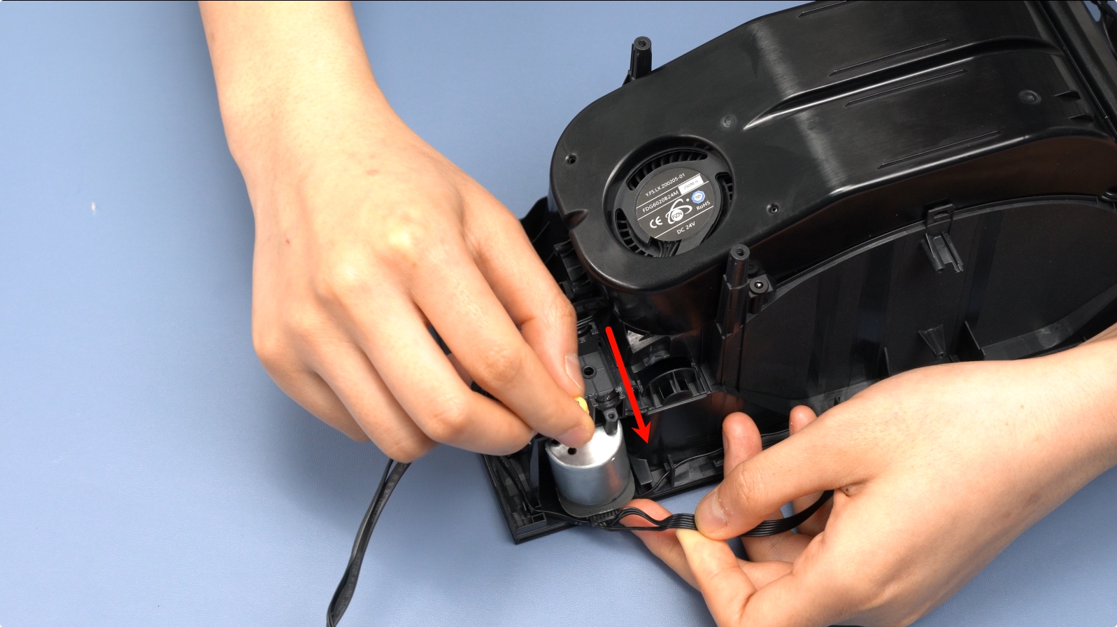
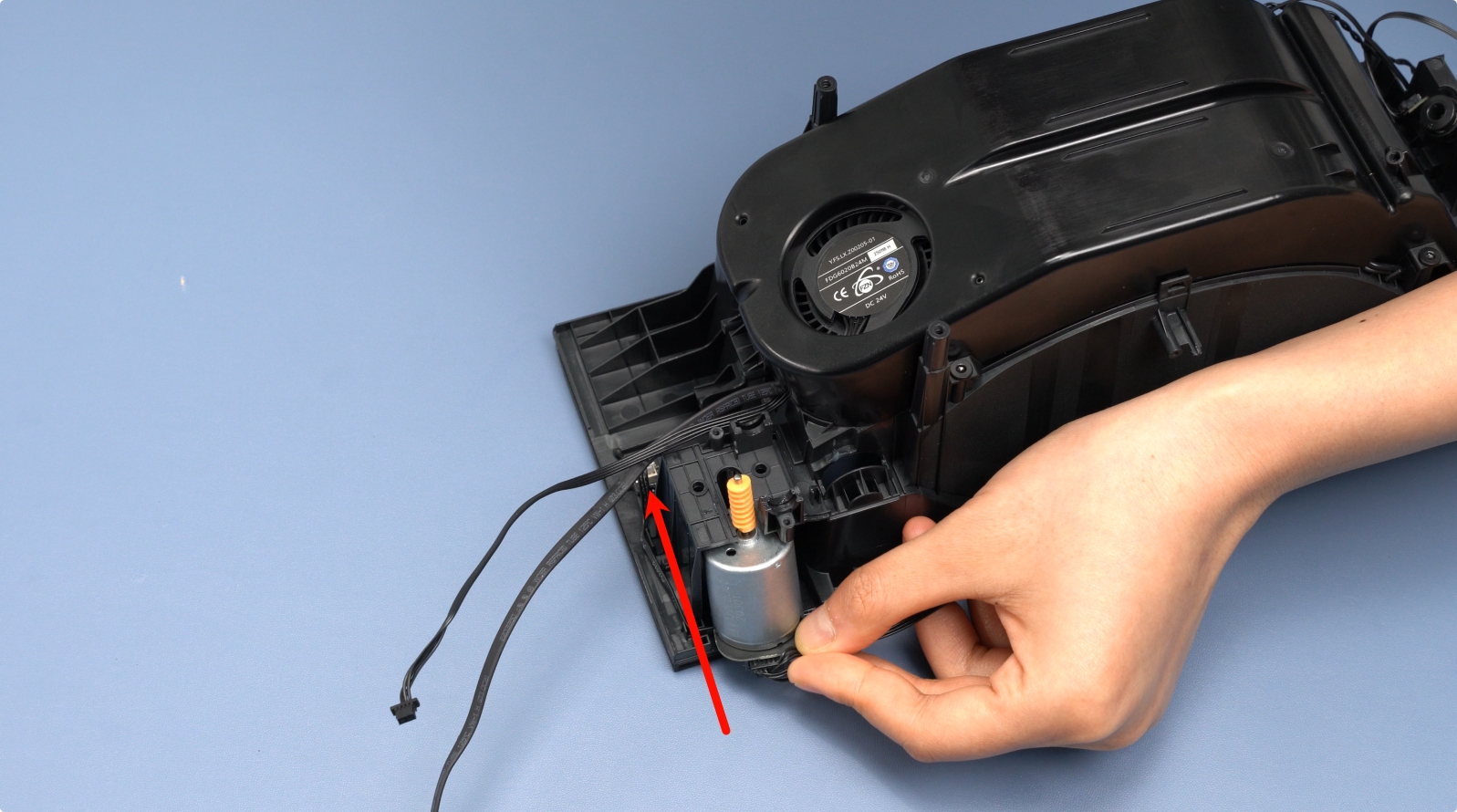
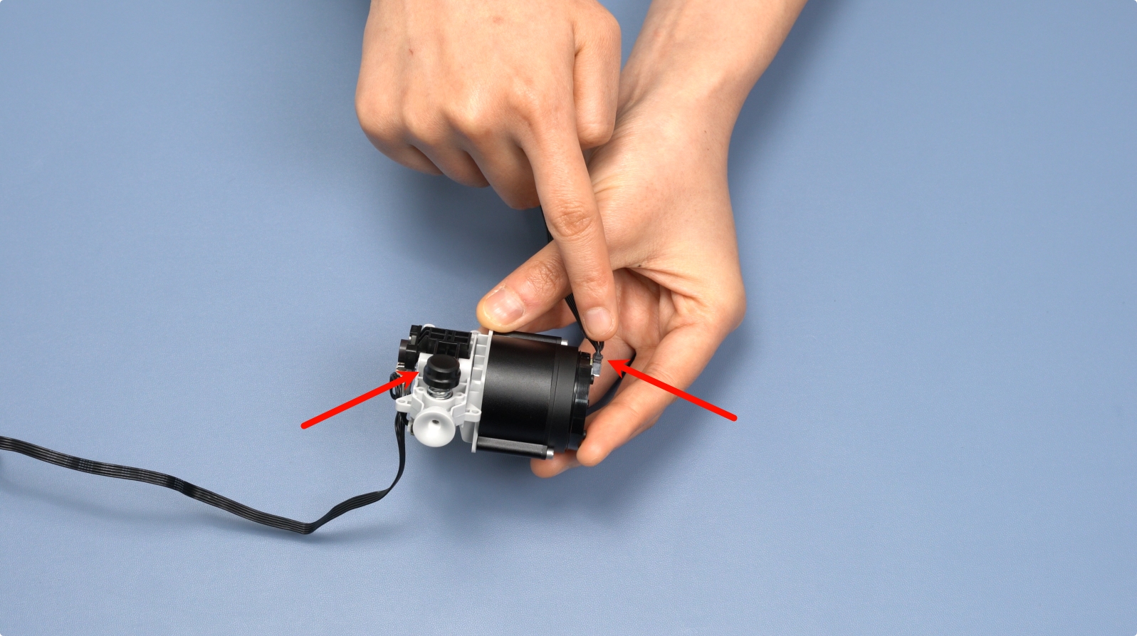
Press the material release button to push out the feeder.
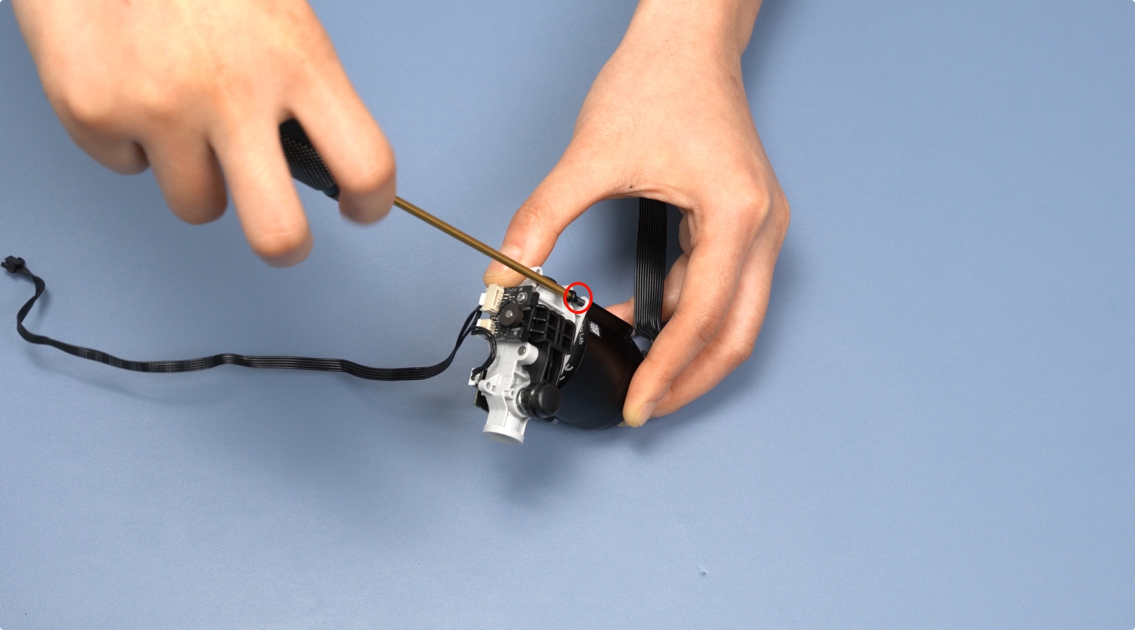
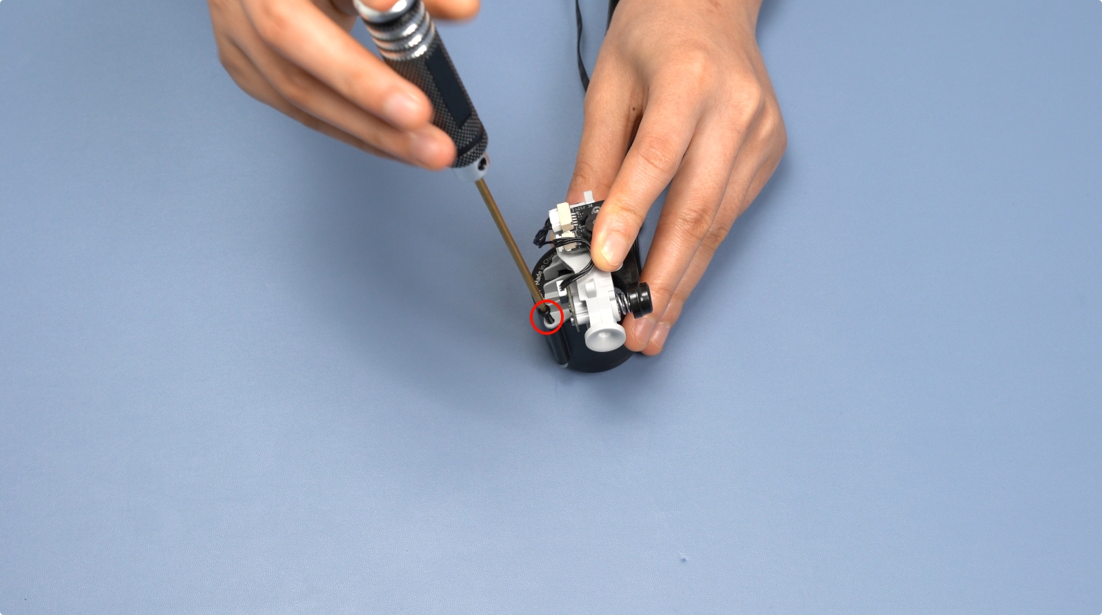
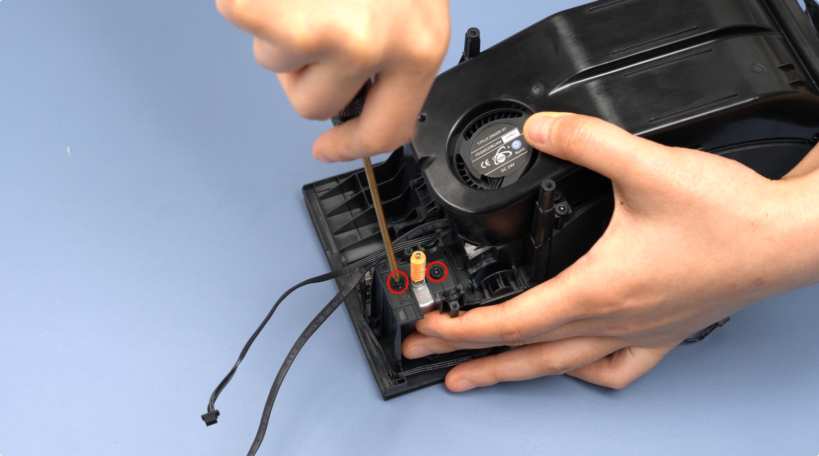
Remove the two feeder motor screws (M2.5×8).
 |
 |
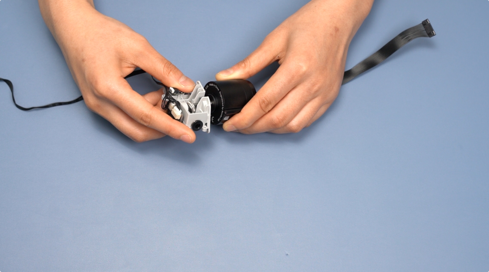
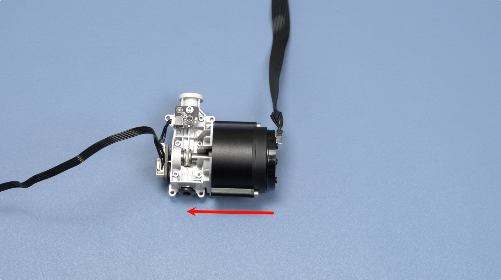
Remove the feeder motor and drive gear, ensuring the drive gear is kept safe to avoid loss.
 |
 |
¶ 5. Remove the Filament Retraction Assembly
Remove the two arm cover screws (BT2×5) and take out the arm cover.
 |
 |
Pinch both sides of the arm assembly and lift it slowly.
 |
 |
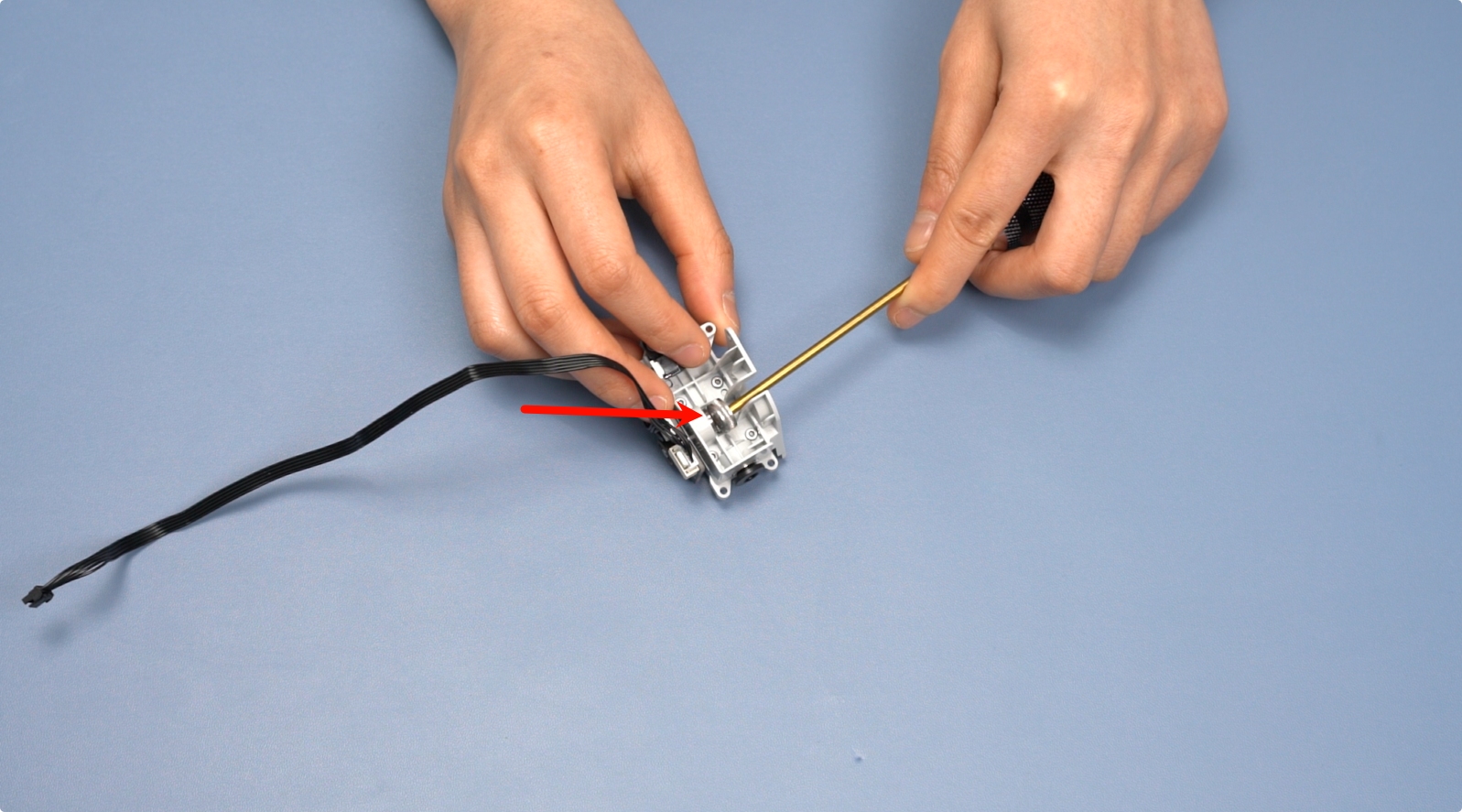
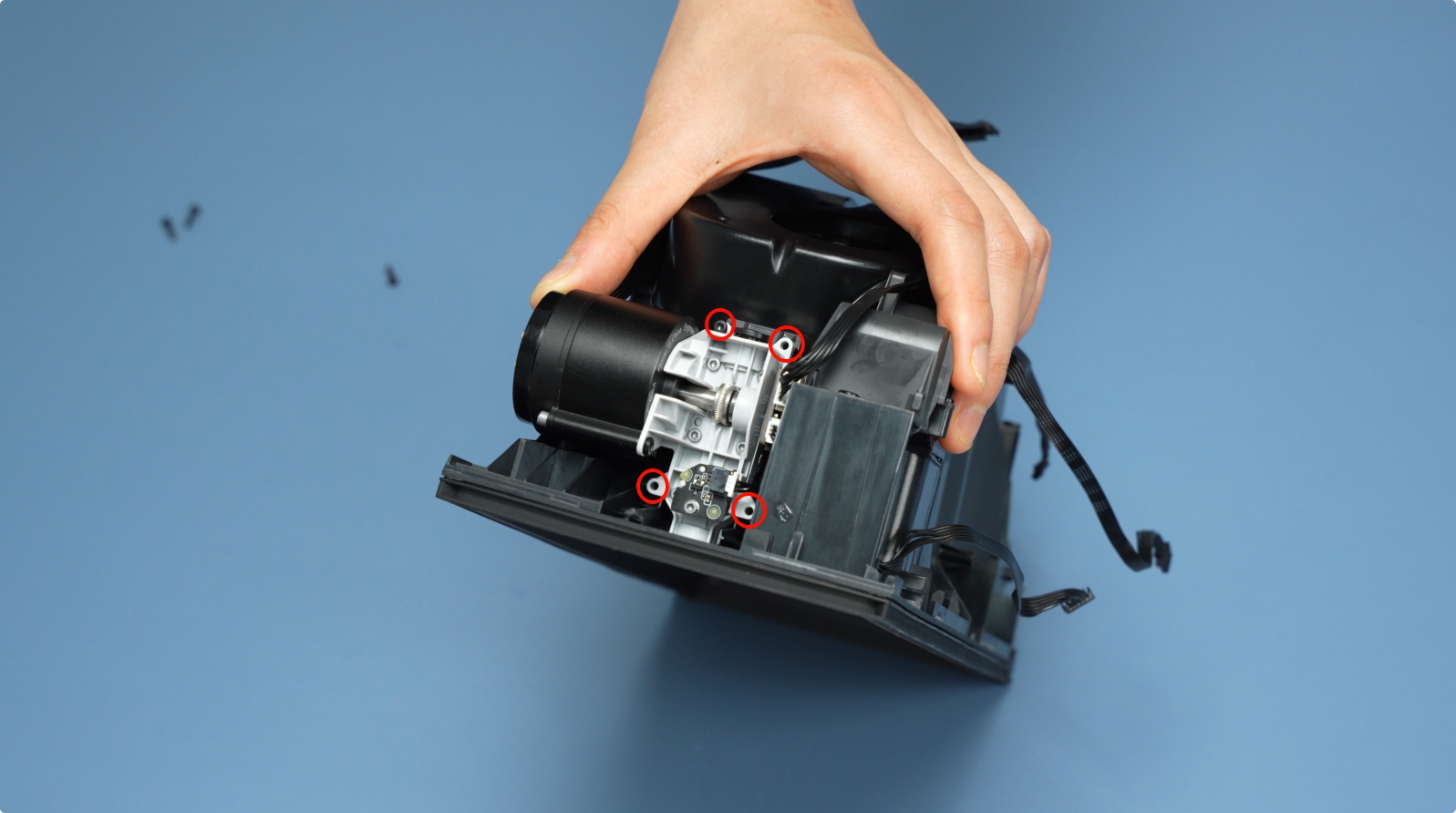
Remove the two retraction motor screws (M3×5) and slide the motor outward.
 |
 |
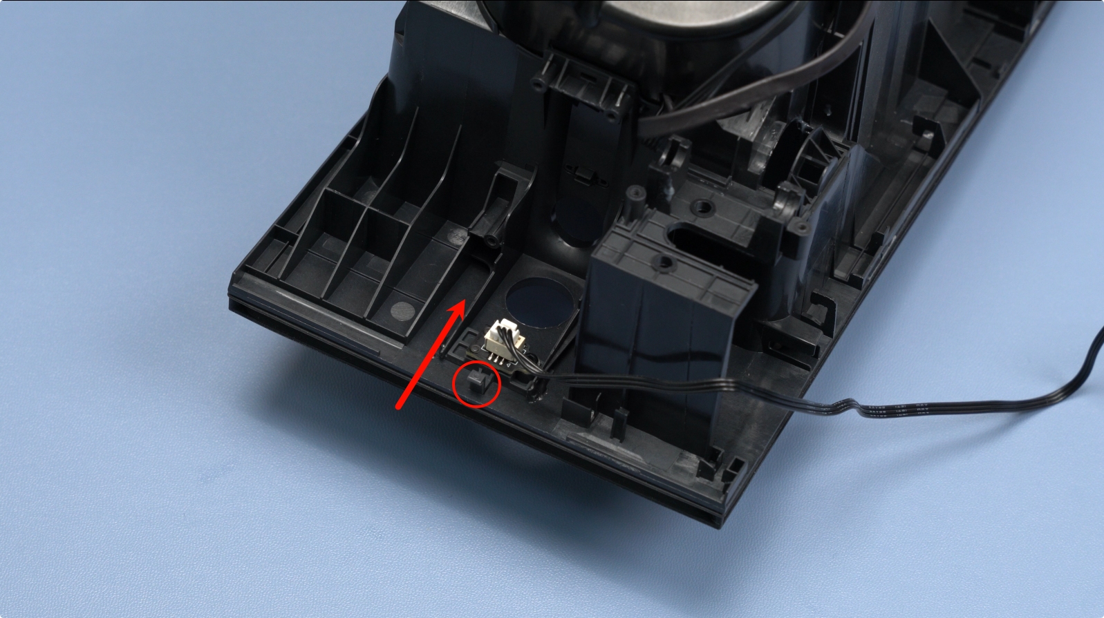
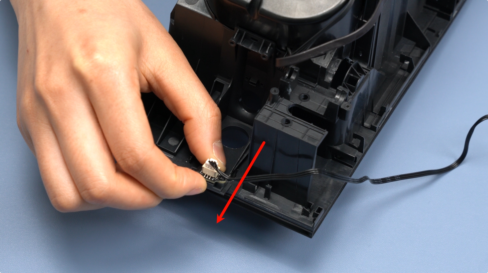
¶ 6. Remove the Lid Status Hall Sensor
Push the fixing latch backward, then remove the lid Hall sensor board.
 |
 |
¶ 7. Remove the RFID Coil
Remove the RFID screw (BT2×5) and gently pull out the RFID coil.
 |
 |
¶ 8. Remove the Feeder Hall Sensor Assembly
Remove the two Hall sensor screws (BT2×5) and take out the sensor.
 |
 |
¶ 9. Remove the AMS HT Heating Unit
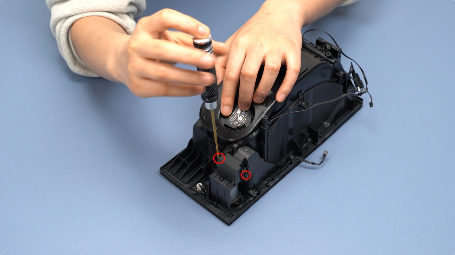
Remove the four screws (BT2×6) on both sides.
 |
 |
Use an H1.5 screwdriver to release the side latches, then lift the heating unit.
 |
 |
¶ 10. Remove the Power Socket
Press the power socket latch and slide it backward to remove it along with the cable.
 |
 |
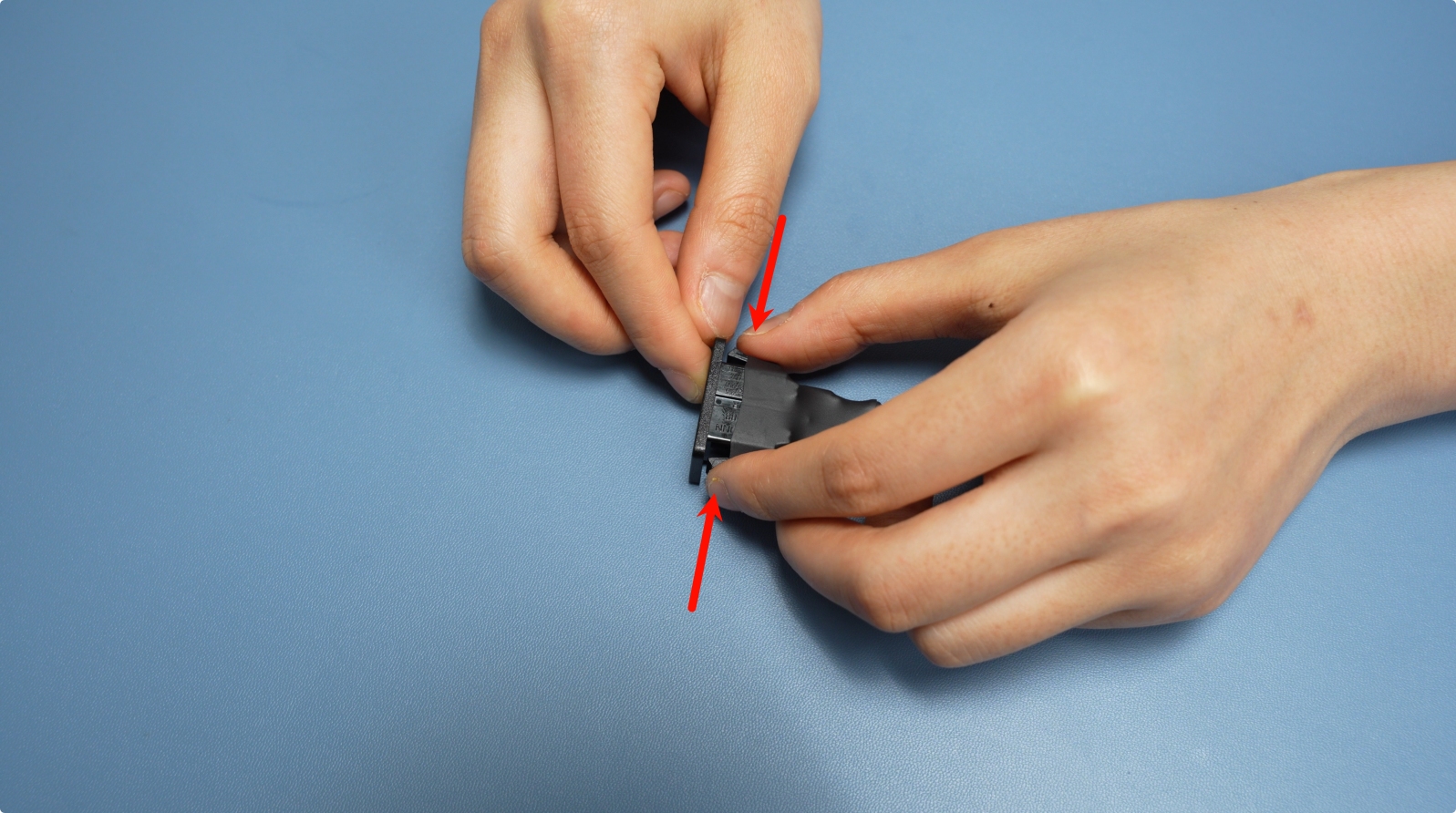
Note: The power socket has elastic latches on both ends. Press both latches simultaneously to release it.
¶ 11. Remove the AMS HT Power Board
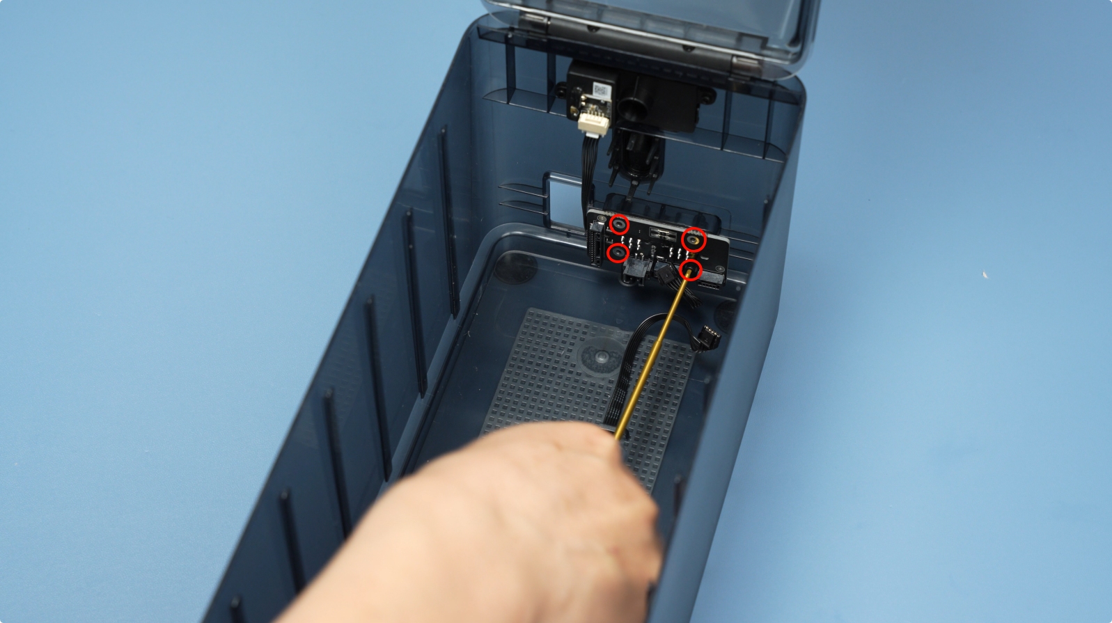
Disconnect the two cables from the Air Inlet Unit, remove the four power board screws (BT2×5), and gently take out the power board.
 |
 |
¶ 12. Remove the Air Inlet Unit
Remove the four screws (BT2×4) and take out the Air Inlet Unit.
 |
 |
¶ 13. Remove the Top Lid Assembly
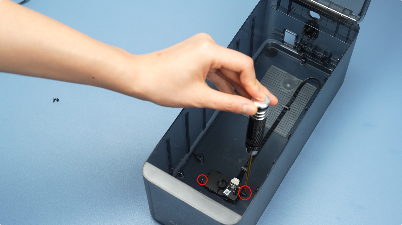
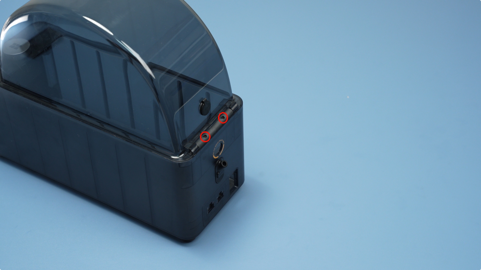
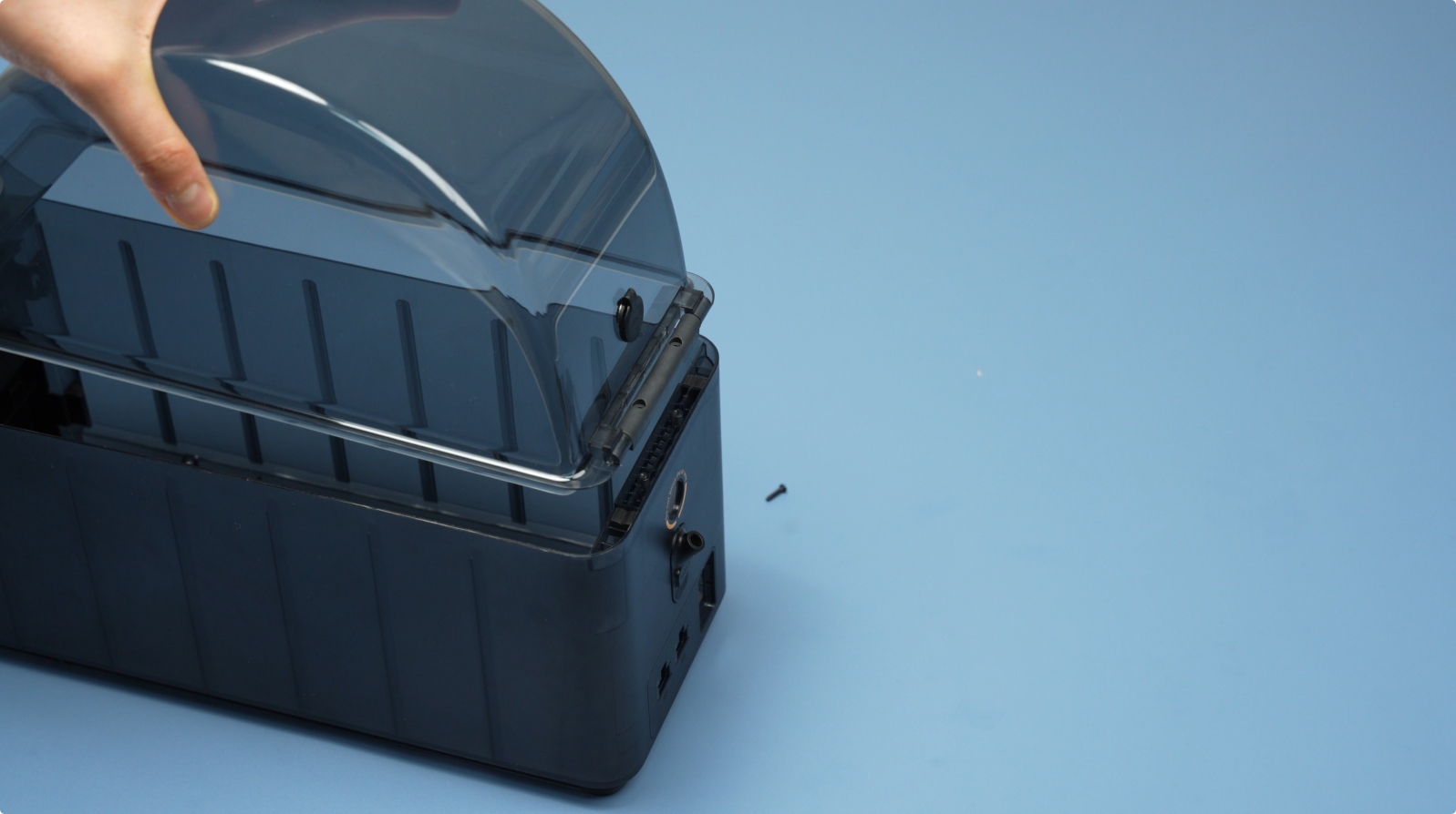
Remove the two top lid screws (BT2×8) and lift the top lid.
 |
 |
¶ 14. Remove the Screen Assembly
Release the four latches on both sides before removing the screen.
 |
 |
Pull the screen assembly backward from the bottom to remove it.
 |
 |
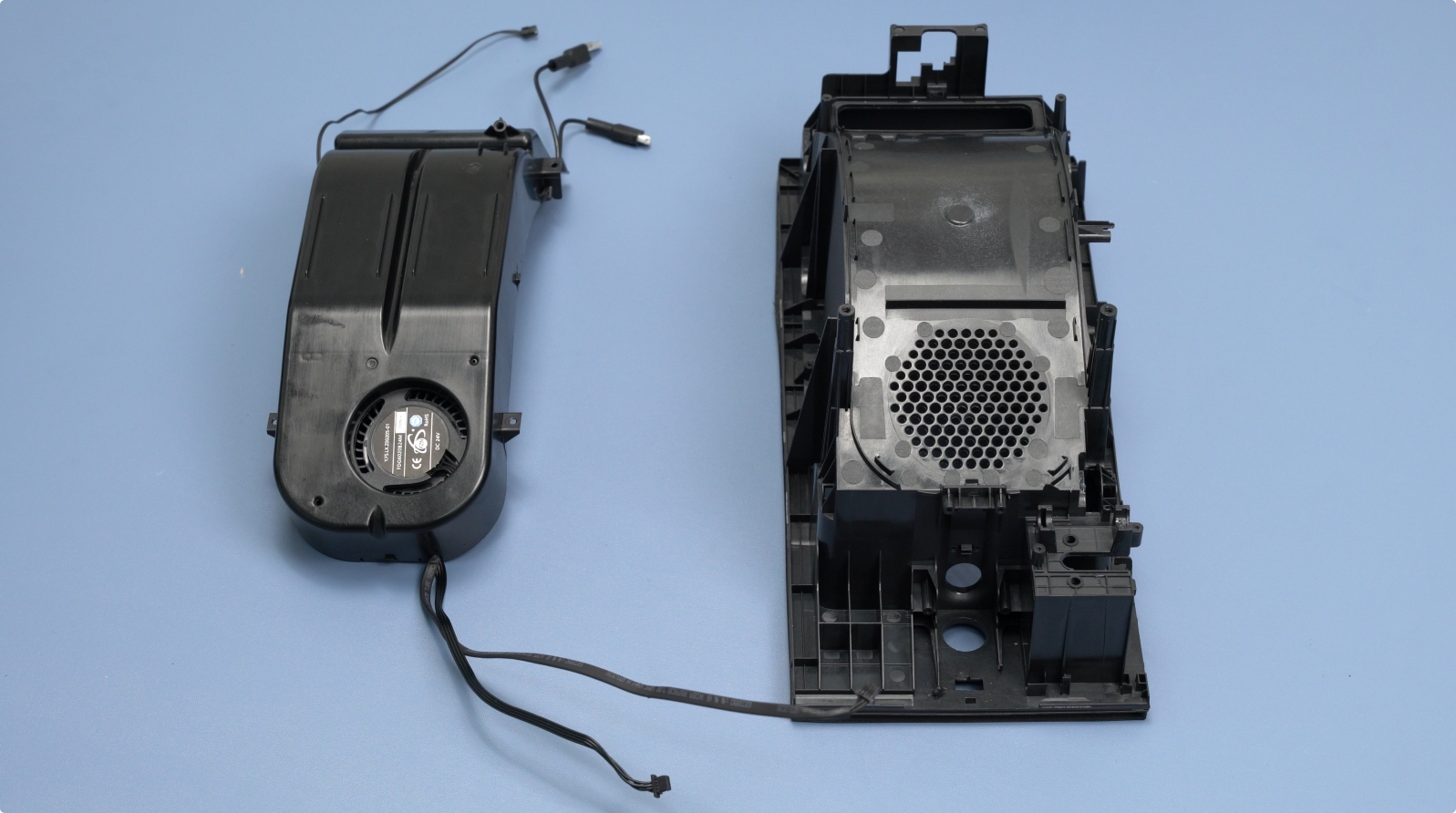
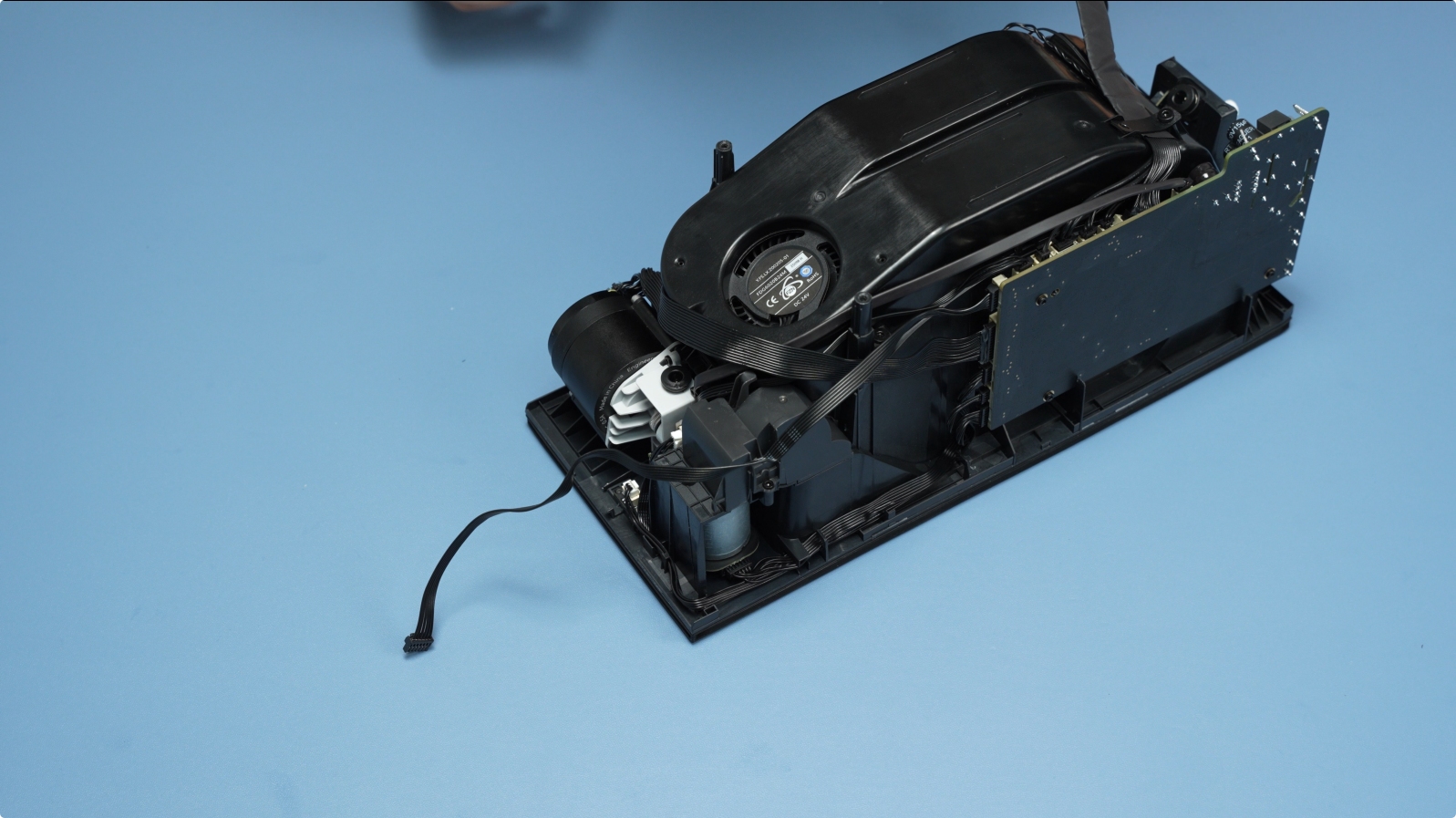
The fully disassembled state is shown below.
¶ Assembly Guide
¶ 1. Install the Screen Assembly
Ensure the screen faces outward. Align and secure the four latches.
¶ 2. Install the Top Lid Assembly
Place the top lid into its slot and secure it with two screws (BT2×8).
|
|
¶ 3. Install the Air Inlet Unit
Note: Distinguish between short and long cables. Short cables connect to the rear, and long cables connect to the bottom. Secure each unit with two screws (BT2×4).
|
|
¶ 4. Install the AMS HT Power Board
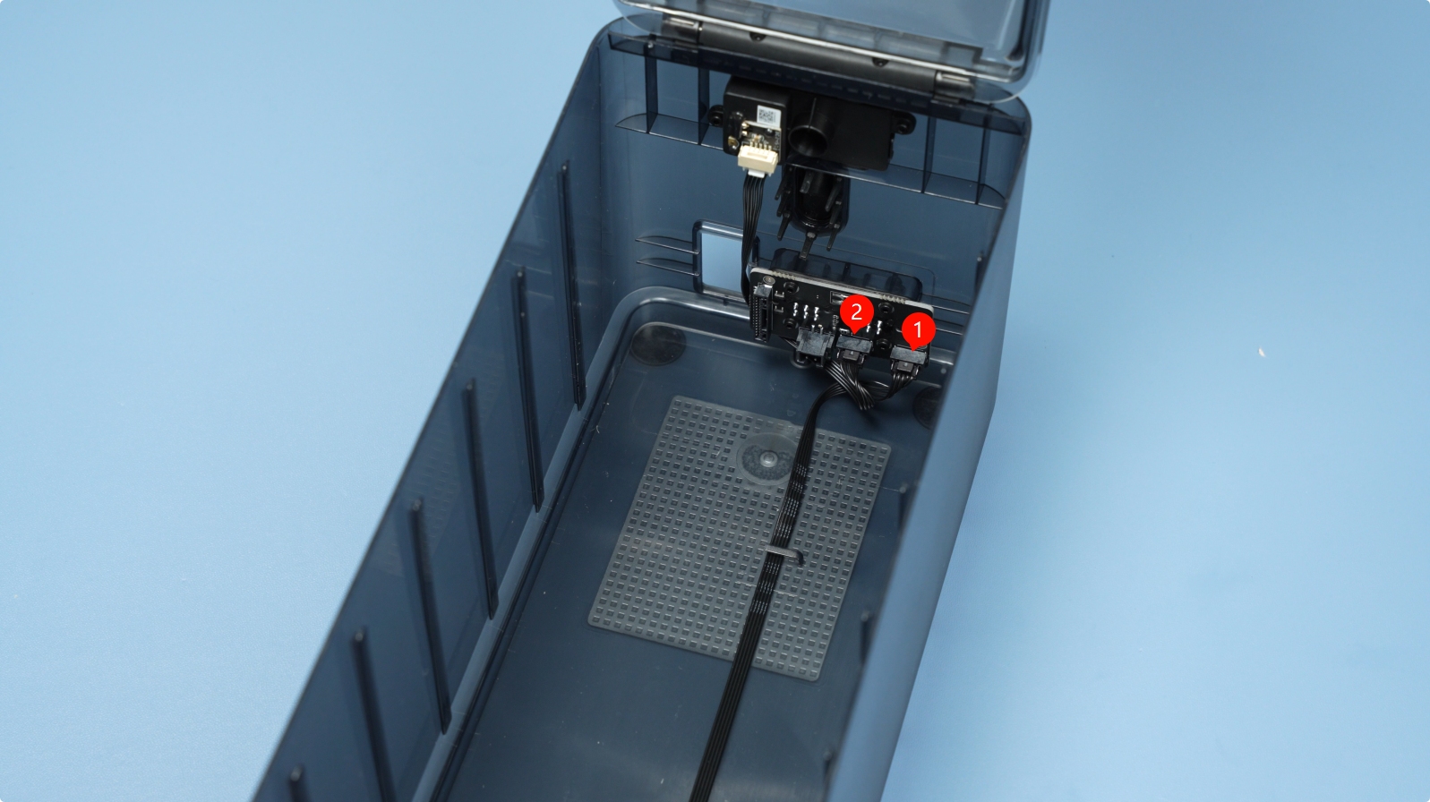
Place the power board with the three-connector side facing the bottom. Secure it with four screws (BT2×5). Connect the Air Inlet Unit cables: bottom to #1, top to #2.
|
|
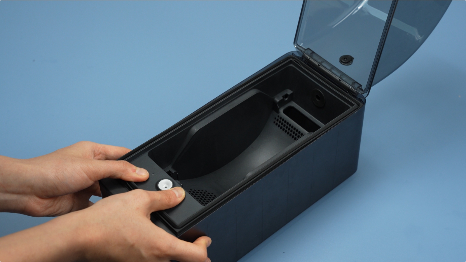
¶ 5. Install the Power Socket
Route the AMS HT Power Socket Cable through the back of the AMS HT. Before securing the power socket, ensure the rubber gasket is properly inserted into the slot. Otherwise, the installation may result in looseness after completion.
Next, press the power switch socket into place until you hear a "click" sound, indicating it is securely installed.
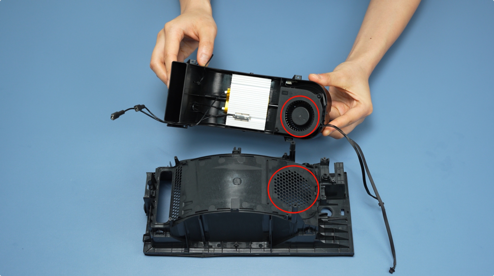
¶ 6. Install the AMS HT Heating Unit
Align the fan side with the ventilation hole and press it into place. Secure with four screws (BT2×6).
 |
 |
¶ 7. Install the Feeder Hall Sensor Assembly
Route the cable through the hole and secure the sensor with two screws (BT2×5).
 |
|
¶ 8. Install the RFID Coil
Insert the RFID coil into its slot and secure it with a screw (BT2×5).
 |
|
¶ 9. Install the Lid Status Hall Sensor
Slide the board into the slots until the latch clicks. Organize the cables into the channel.
|
 |
¶ 10. Install the Filament Retraction Assembly
Install the retraction motor, ensuring the cable faces outward, and secure it with 2 screws (M3×5).
 |
|
Pinch both sides of the arm assembly and install it into the slot.
|
|
Install the arm cover and secure it with 2 cover screws (BT2×5).
 |
|
¶ 11. Install the Feeder Unit
Attach the drive gear to the feeder motor. Insert the motor into the feeder, ensuring the material release button and motor cable face the same direction. Secure with two screws (M2.5×8).
 |
 |
Install the feeder onto the main frame and secure it with four screws (BT2×8).
Organize the cables into the channel.
 |
 |
¶ 12. Install the AMS HT Mainboard
Mainboard Connection Diagram
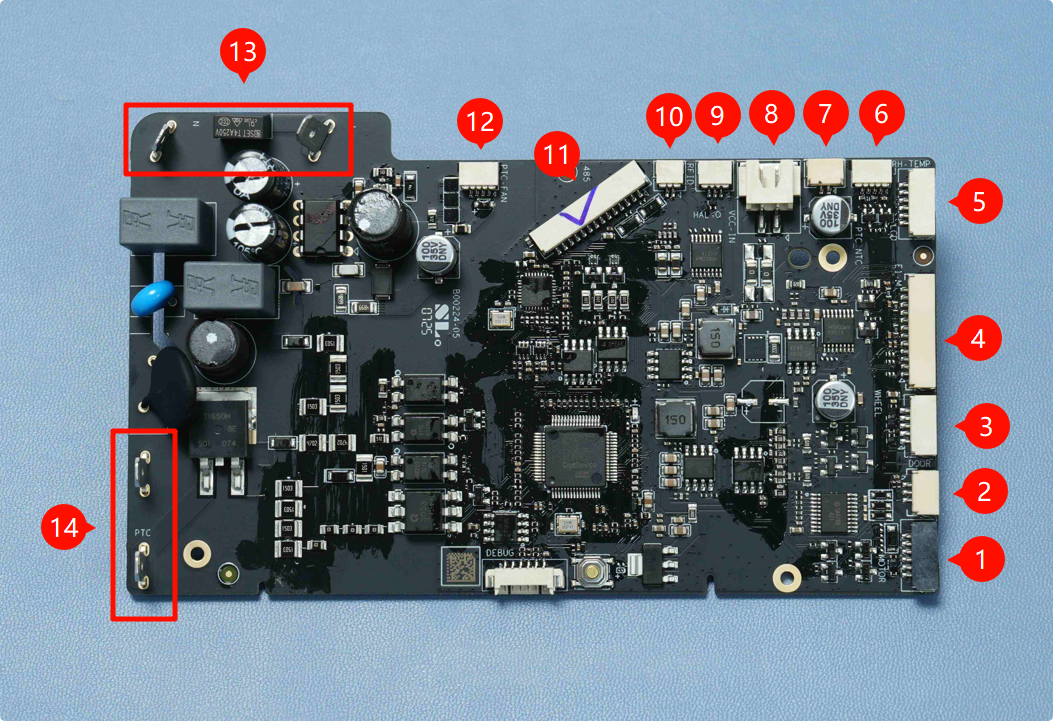
| 1. Filament Retraction Motor | 2. Lid Status Hall Sensor | 3. Odometer Board |
| 4. 3520 AMS Internal Assist Motor | 5. LCD Screen | 6. Temperature & Humidity Sensor |
| 7. Heating Unit Thermistor | 8. Mainboard Power Connector | 9. Feeder Hall Sensor Assembly |
| 10. RFID Coil | 11. Mainboard Communication Connector | 12. Heating Unit Fan |
| 13. Mainboard AC Input | 14. Heating Unit AC Input |
Connect the mainboard cables before securing the screws.
The interfaces labeled 1-4 in the figure below are:
- Filament Retraction Motor
- Lid Status Hall Sensor
- Odometer Board
- 3520 AMS Internal Assist Motor
After completing the side cable installation, proceed to connect the top 5 cables in sequence.
- Temperature & Humidity Sensor
- Thermistor
- Feeder Hall Sensor Assembly
- RFID Coil
- Heating Unit Fan
Gently tug the cables to ensure they are secure.
Connect the heater cable and reinstall the insulation sleeve.
Note: Polarity does not matter here.
Insert the mainboard into its slot and secure it with three screws (BT2×5).
Organize the rear cables: Place the four thin cables at the bottom, then press the thicker mainboard communication cable on top. Secure with a retainer screw (BT3×5).
 |
 |
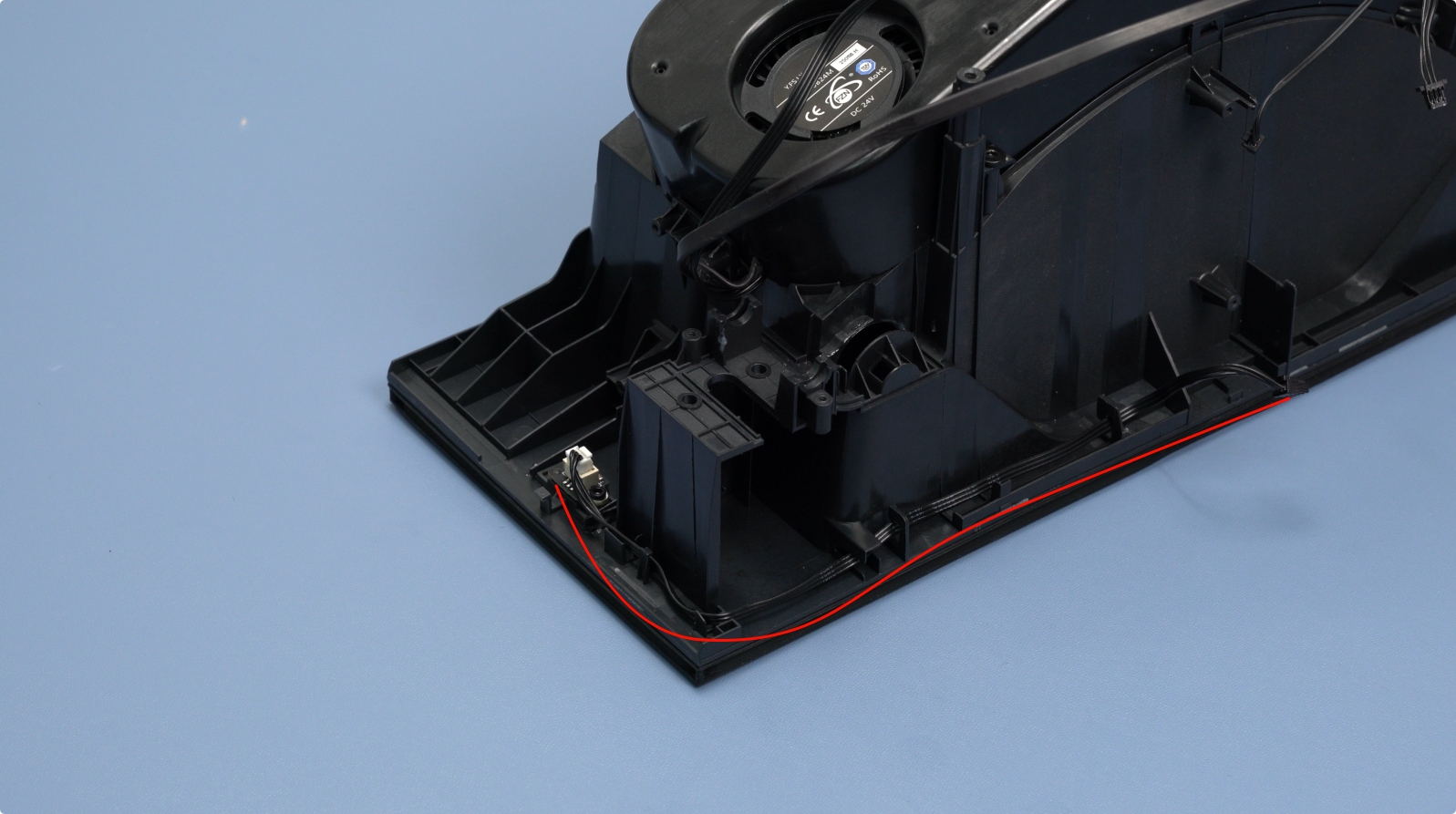
Rotate the AMS HT 180° and organize the front cables into the channel.
 |
 |
¶ 13. Install the AMS HT Main Frame
Connect the PTFE tube between the feeder and the outlet.
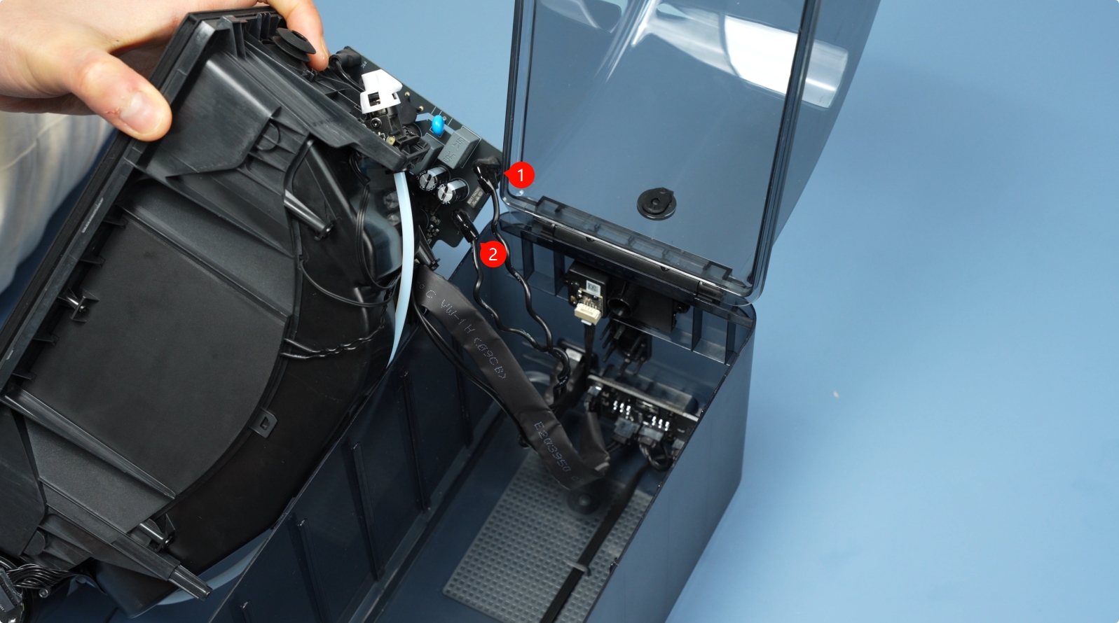
Connect the two cables:
- Mainboard communication cable (14-pin).
- Mainboard power cable (2-pin).
Connect the power socket cable to the mainboard and reinstall the insulation sleeve.
Note: Polarity does not matter here.
Connect the front screen cable and secure it in the channel.
 |
 |
Hook the protruding cables with your fingers and install the main frame into the bottom cover.
 |
 |
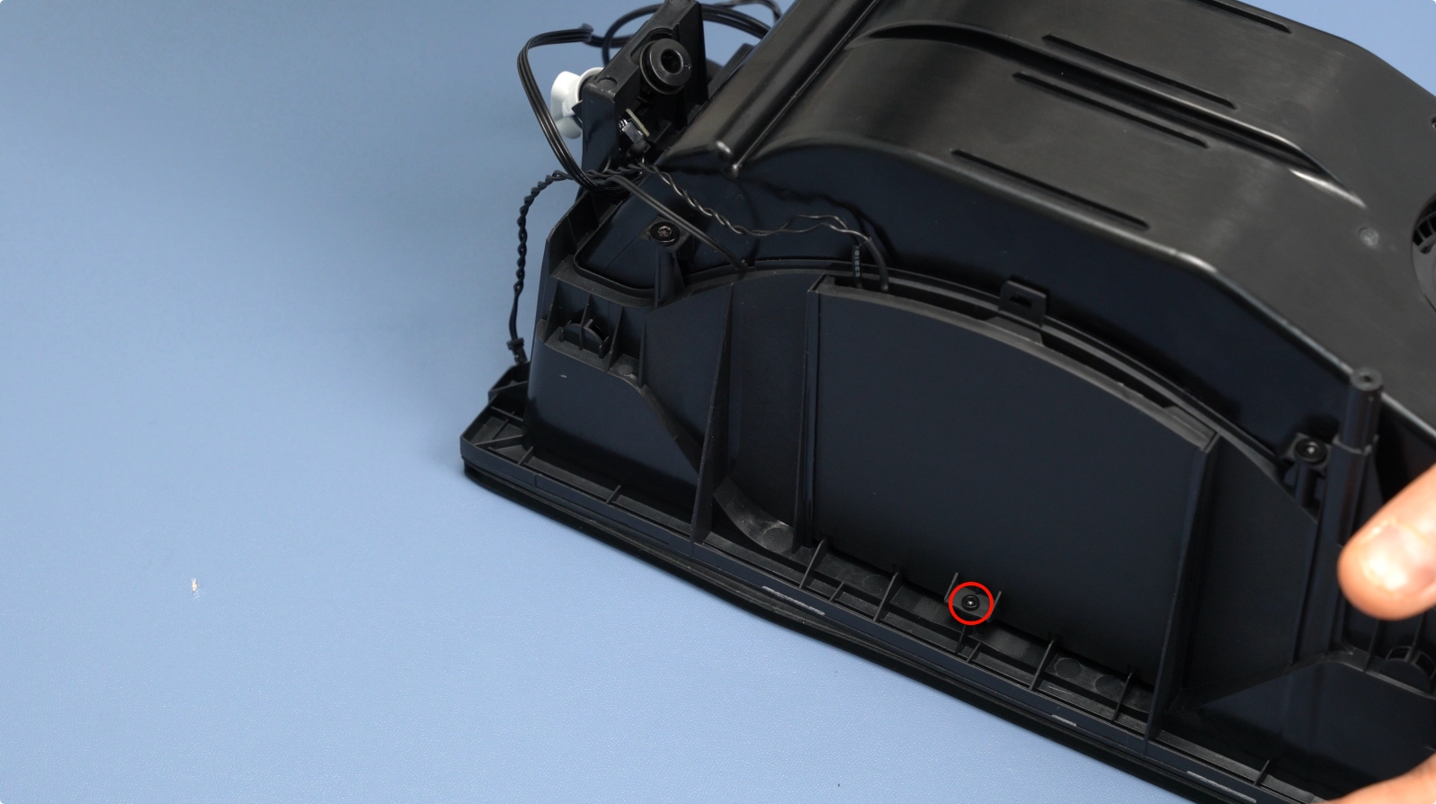
Ensure the main frame is fully seated and secure it with two bottom screws (BT3×8).
 |
 |
¶ 14. Install the Active and Driven Support Shafts
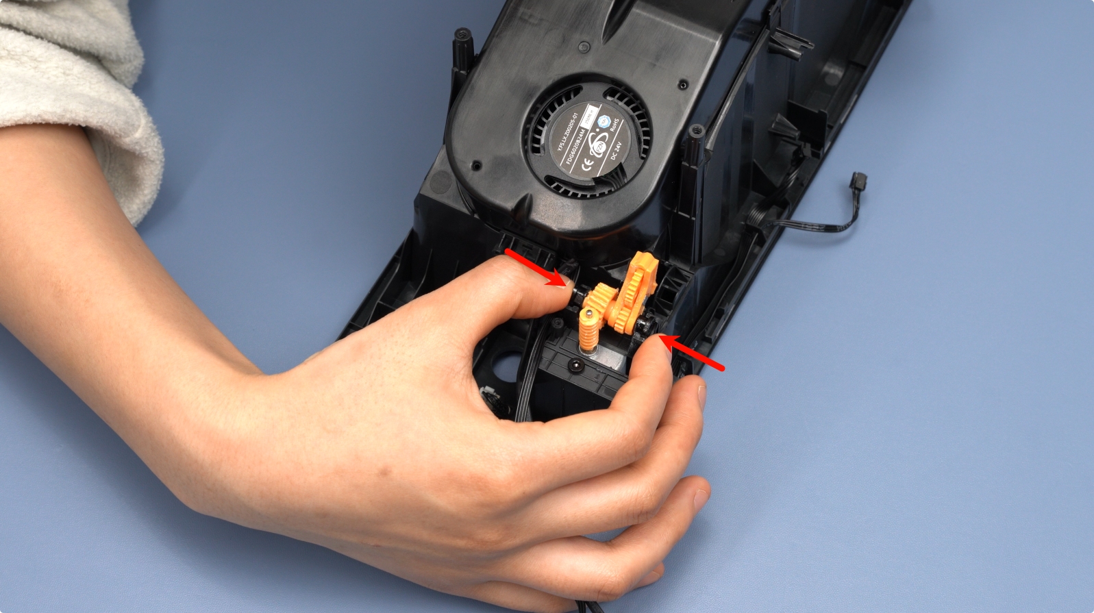
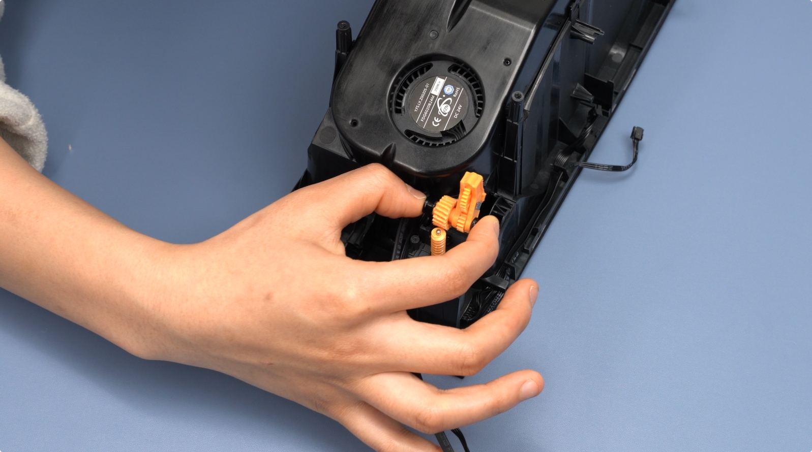
Press the Active Support Shaft into the front slot until it clicks. Align the black gear with the yellow gear inside the main frame.

Press the Driven Support Shaft into the main frame until it clicks.

Note: After installation, manually rotate the shafts to ensure smooth movement.
¶ 15. Insert the PTFE Tube into the AMS HT Back
Push the PTFE tube into the rear of the AMS HT. Pull it gently to confirm it is secure.
¶ Appendix
¶ Installing the AMS HT Rear Silicone
-
Place the rear silicone onto the corresponding mounting hole of the enclosure, ensuring that the silicone pins are aligned with the holes of AMS HT.
-
Hold the silicone frame firmly against the enclosure with one hand. (At this stage, the pins do not push through yet.)
-
From inside the enclosure, gently pull each pin through its hole one by one until it comes all the way through.
- Check that all the pins are fully pulled through and that the silicone sits flush and secure against the enclosure
Tip: Take your time and pull the pins one at a time. Pulling too hard or trying to do them all at once may stretch or deform the silicone. If a pin doesn’t line up correctly, push it back, realign, and try again.
¶ Functional Verification
Connect the power cable and link the AMS HT to the printer. Power on and enable the drying and feeding functions via the printer's interface.
- If the drying function activates and reaches the target temperature, the heating unit is working.
- Test the feeding process. If no errors occur, the replacement is successful.
If issues persist, check all internal cable connections and retry. For further assistance, contact Bambu Lab support.
¶ End Notes
We hope the detailed guide provided has been helpful and informative.
If this guide does not solve your problem, please submit a technical ticket, we will answer your questions and provide assistance.
If you have any suggestions or feedback on this Wiki, please leave a message in the comment area. Thank you for your support and attention!