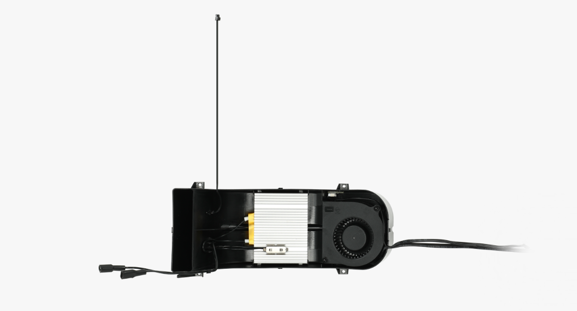
The AMS HT heating unit consists of a heating element, a fan, and NTC temperature sensor.
¶ When to Use
-
Use this guide when the heating element, temperature sensor, or the fan is malfunctioning.
-
Replacement is recommended by Bambu Lab Technical Support.
¶ Required Tools and Materials
-
H1.5 screwdriver
-
H2.0 screwdriver
¶ Safety Warning and Machine State Before Starting Operation
WARNING!
It's crucial to power off the printer before performing any maintenance work on the printer and its electronics, including tool head wires, because leaving the printer on while conducting such tasks can cause a short circuit, which can lead to additional electronic damage and safety hazards.
When you perform maintenane or troubleshooting on the printer, you may be required to disassemble some parts, including the hotend. This process can expose wires and electrical components that could potentially short circuit if they come into contact with each other or with other metal or electronic components while the printer is still on. This can damage the electronics of the printer and cause further damage.
Therefore, it's essential to switch off the printer and disconnect it from the power source before doing any maintenance work. This will prevent any short circuits or damage to the printer's electronics. By doing so, you can avoid potential damage to the printer's electronic components and ensure that the maintenance work is performed safely and effectively.
If you have any concerns or questions about following this guide, open a new ticket in our Support Page and we will do our best to respond promptly and provide you with the assistance you need.
¶ Remove the Old Heating Unit
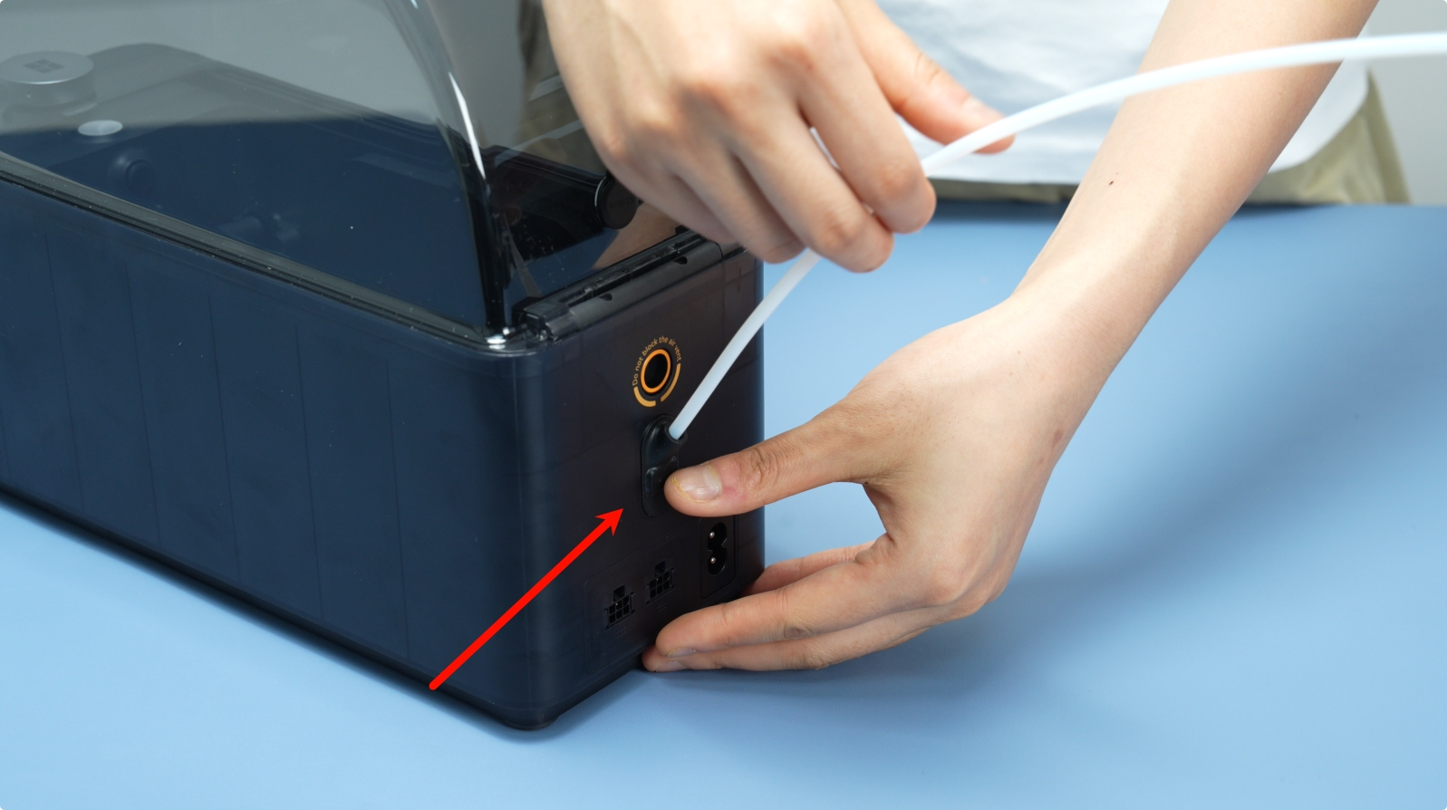
¶ Step 1: Remove the PTFE Tube at the Back of the AMS HT
Press the PTFE tube,release the button on the back of the AMS HT to unlock the fitting, then pull out the PTFE tube.
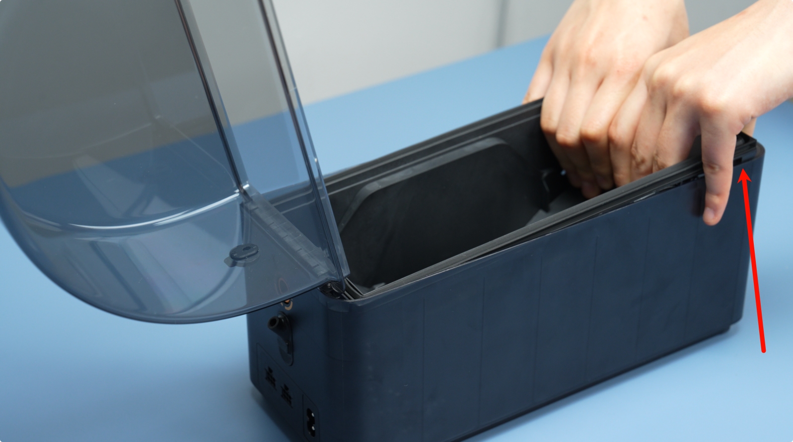
¶ Step 2: Remove the Middle Frame of the AMS HT
First, remove the two bottom screws (BT3*8).

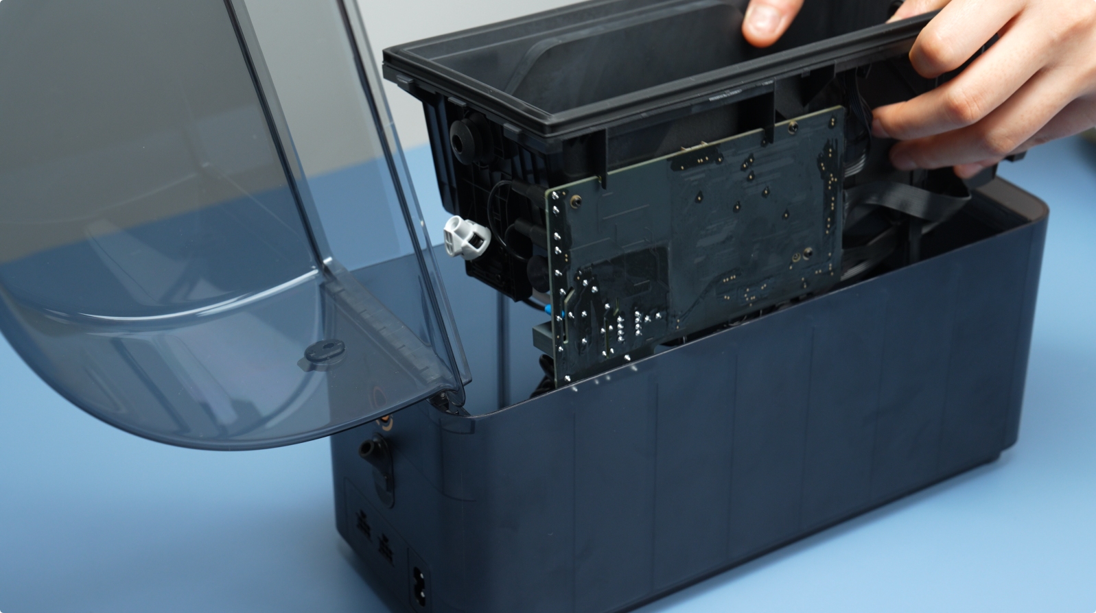
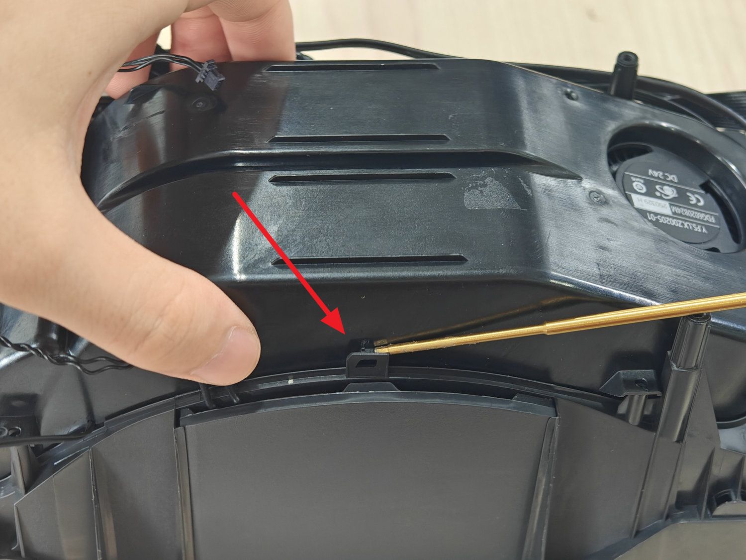
After removing the screws, gently lift the middle frame assembly upward.
 |
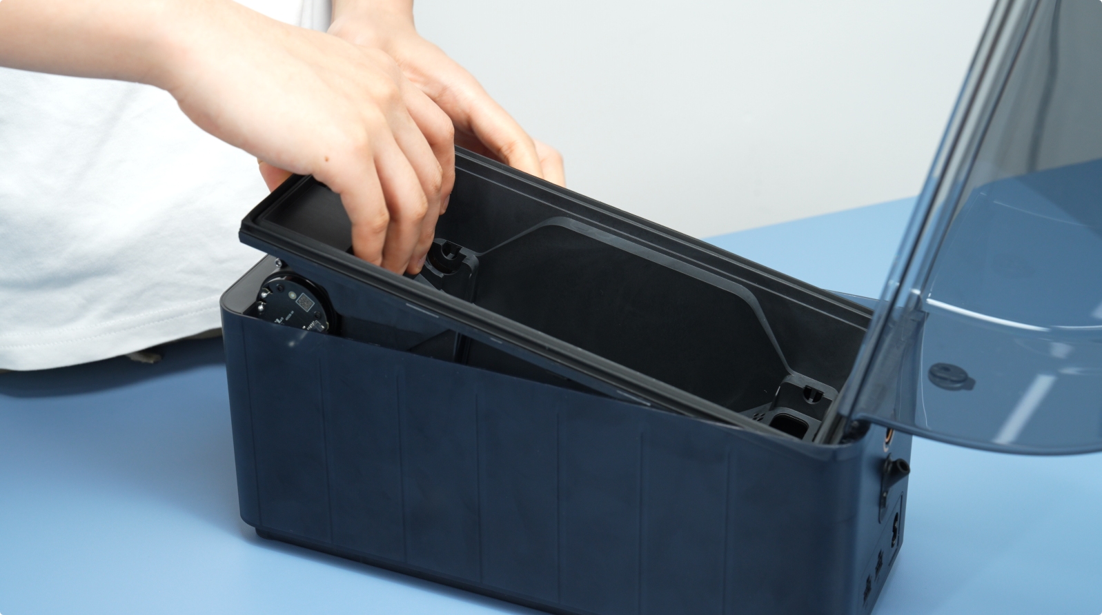 |
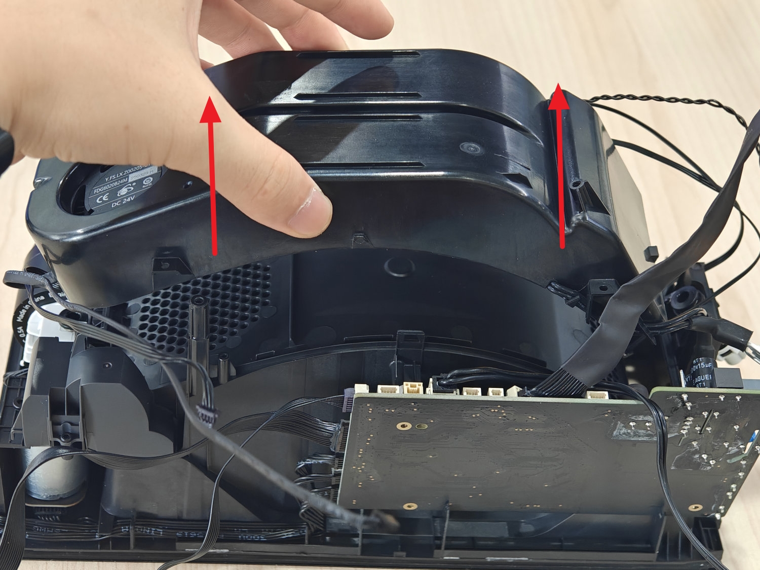
Once there is a gap, continue lifting the middle frame. Do not pull forcefully as the cables are still connected.
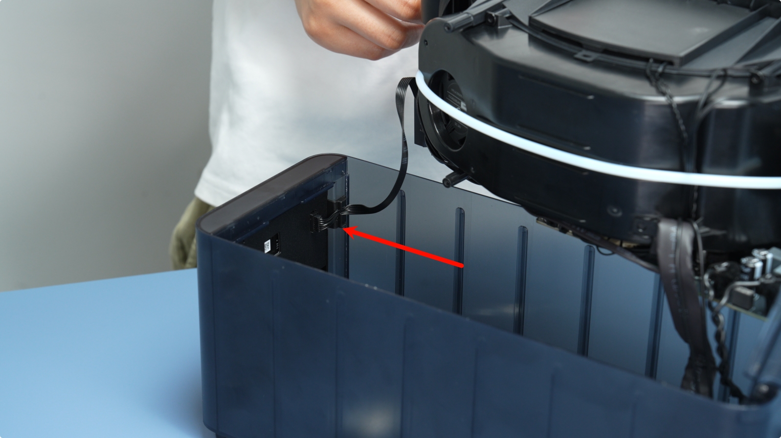
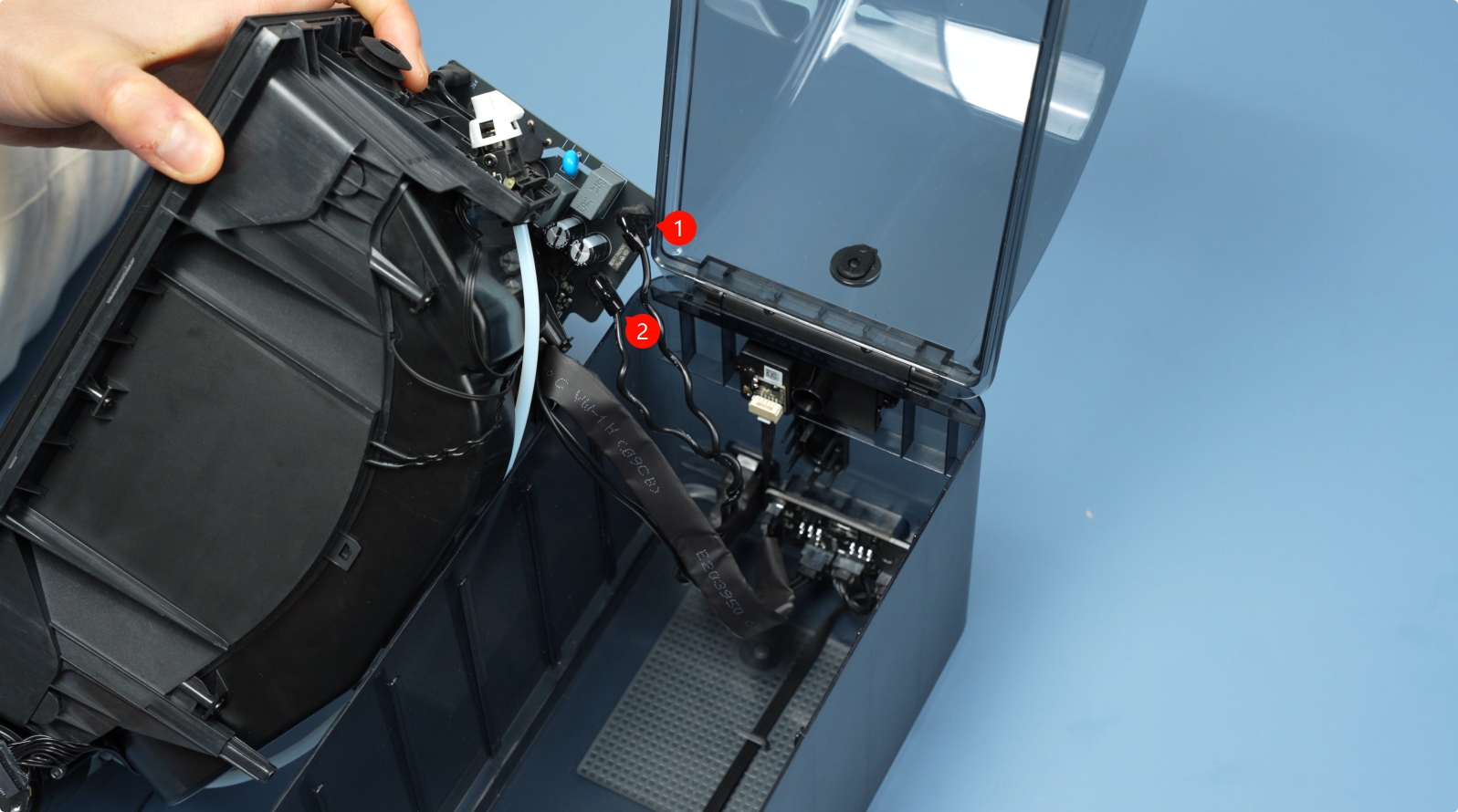
Unlock the latch and disconnect the front display screen cable.
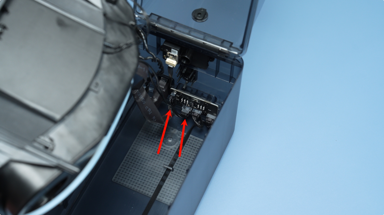
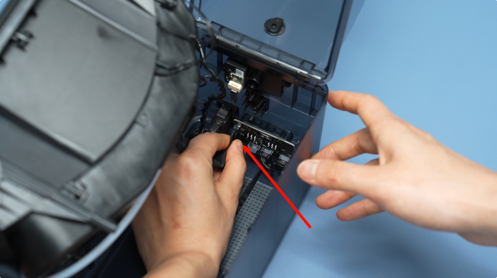
Next, unplug the signal and power cables from the AMS HT power board.
 |
 |
Remove the cable that connects the power socket to the mainboard. Do this by removing the insulation cover, press the latch, and pull out the connector.
 |
 |
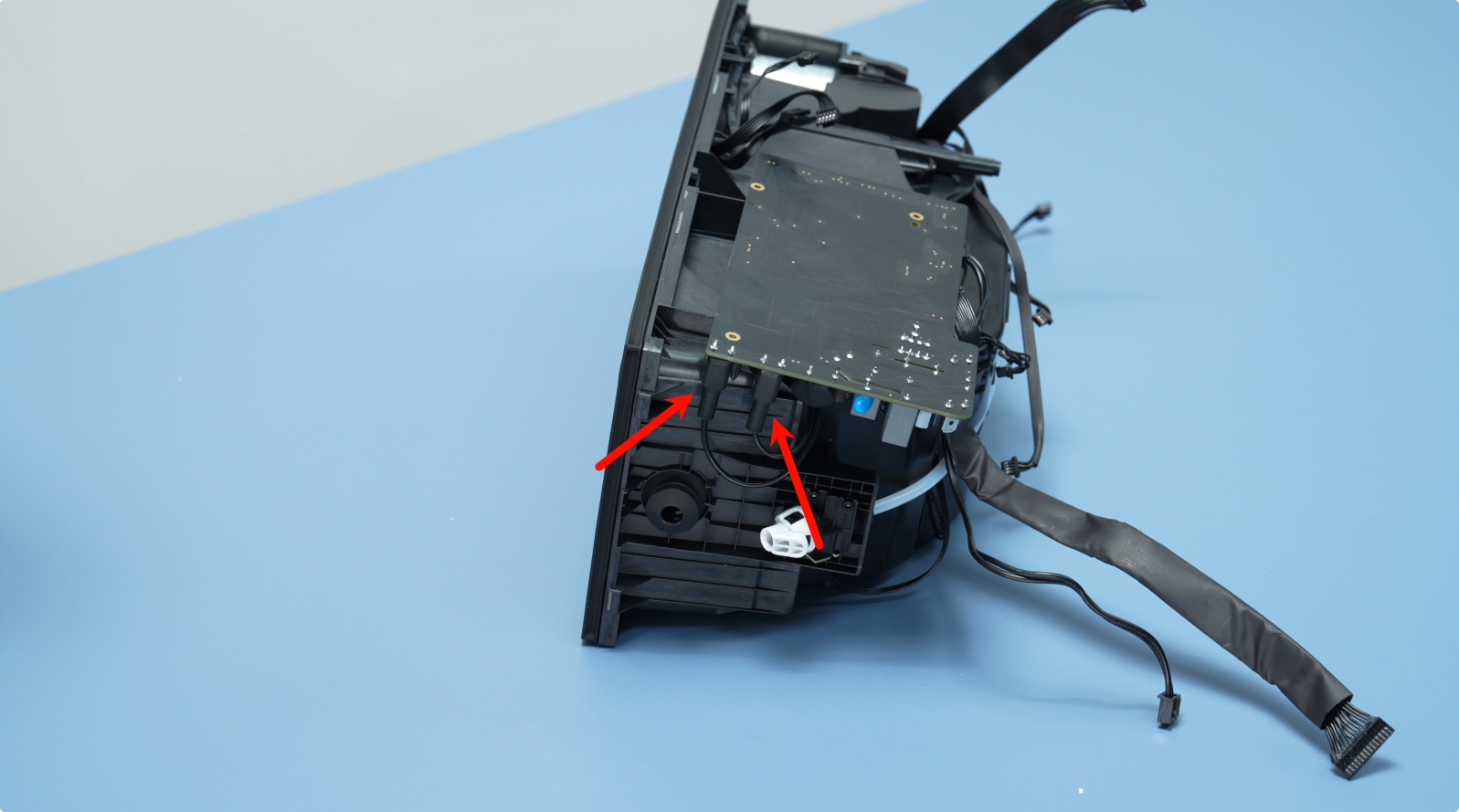
¶ Step 3: Disconnect the Heating Unit Cables
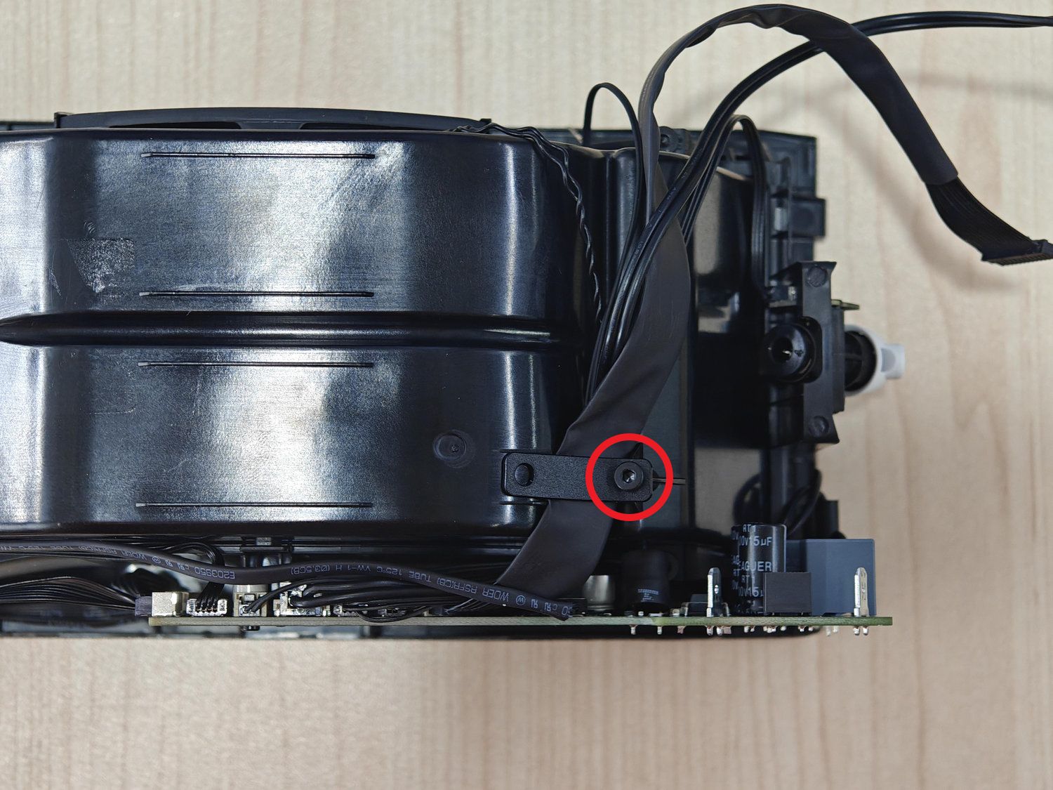
Remove the BT3x5 screw from the cable clamp to loosen and free the cables from the drying component.
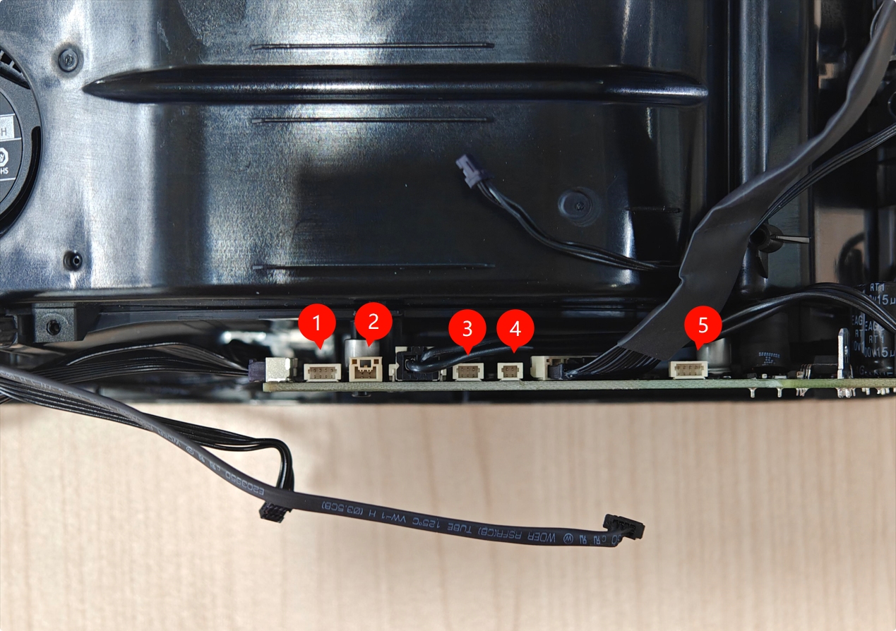
Then remove the following cables from the mainboard:
- Temperature and humidity sensor
- Thermistor sensor
- Feeder Hall Sensor Assembly
- RFID coil
- Heating Unit Fan
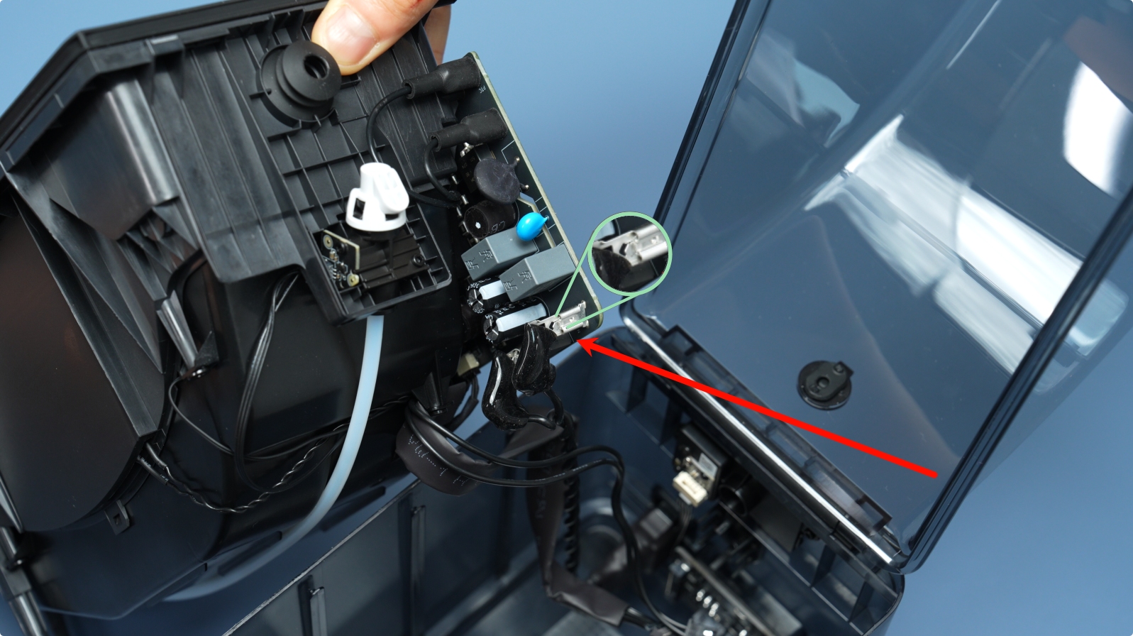
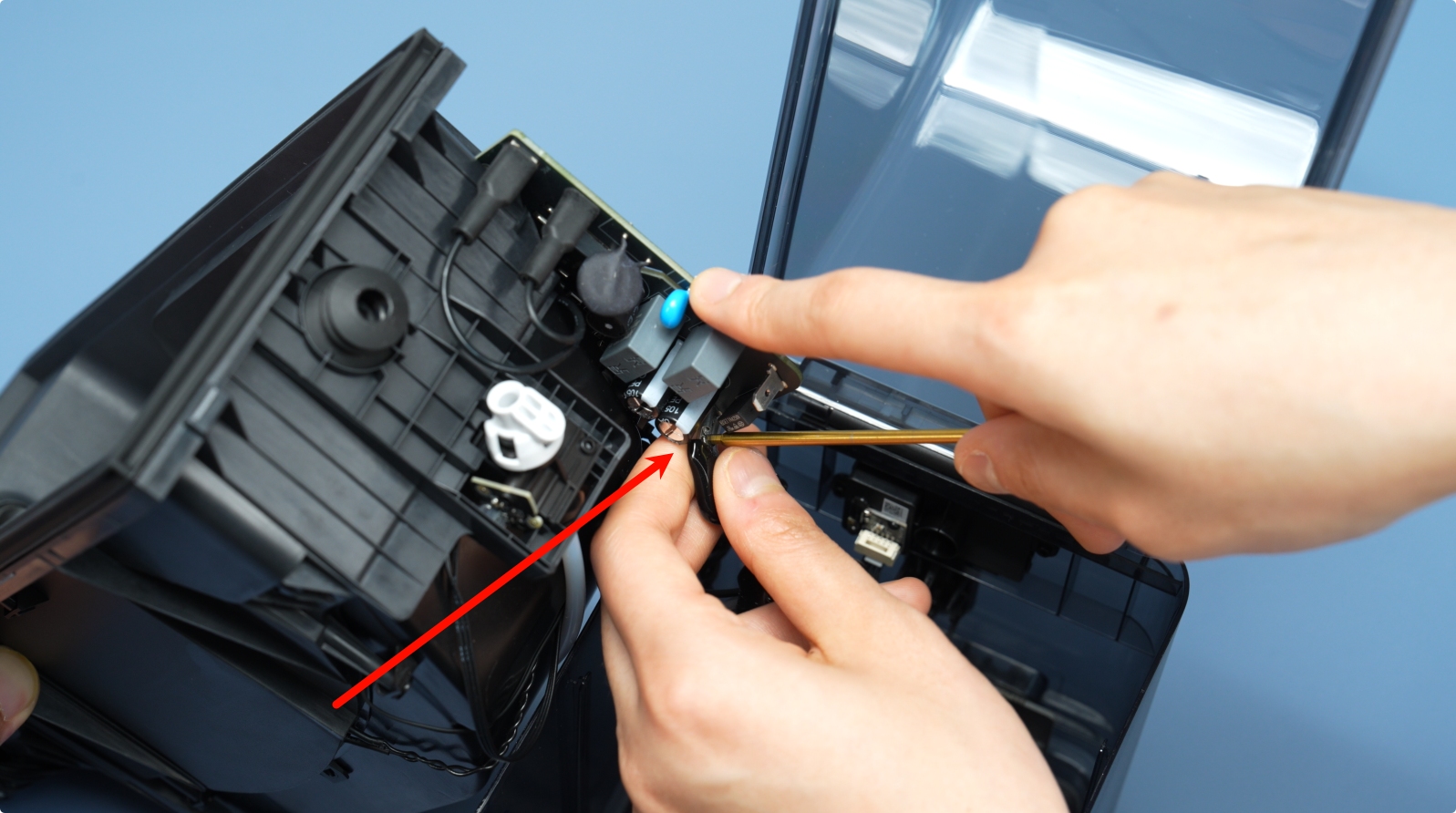
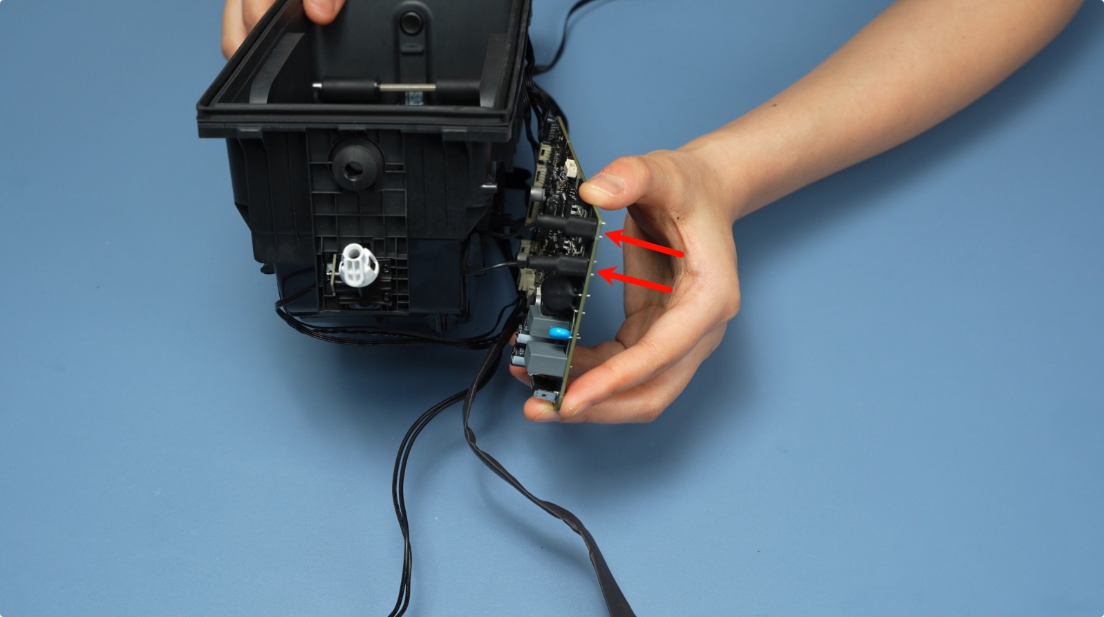
Next, disconnect the heating unit cable on the side of the mainboard. To do this, first remove the insulation cover, press the latch, then gently unplug the cable.
 |
 |
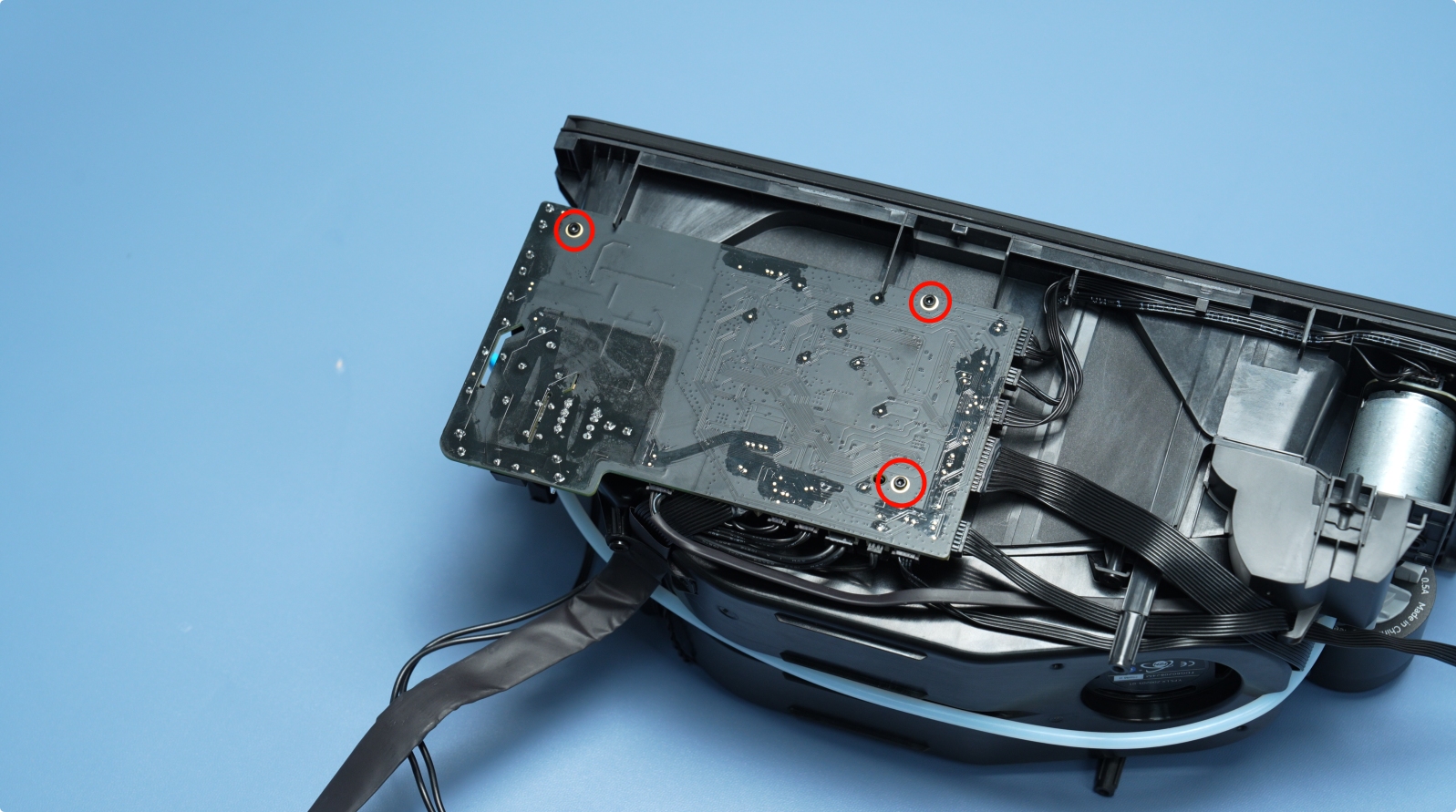
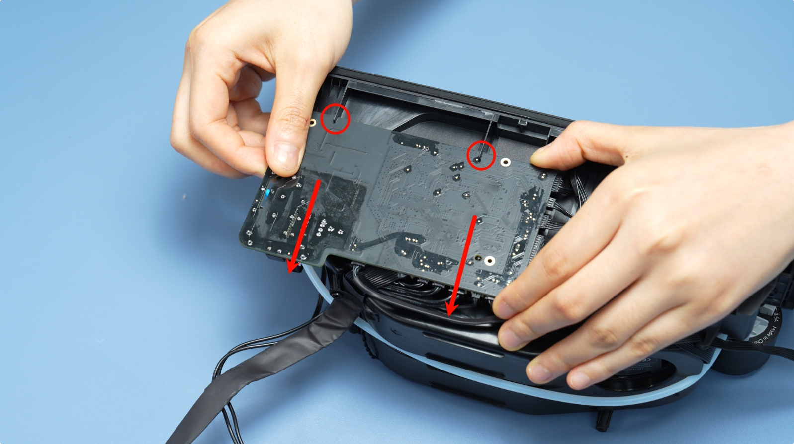
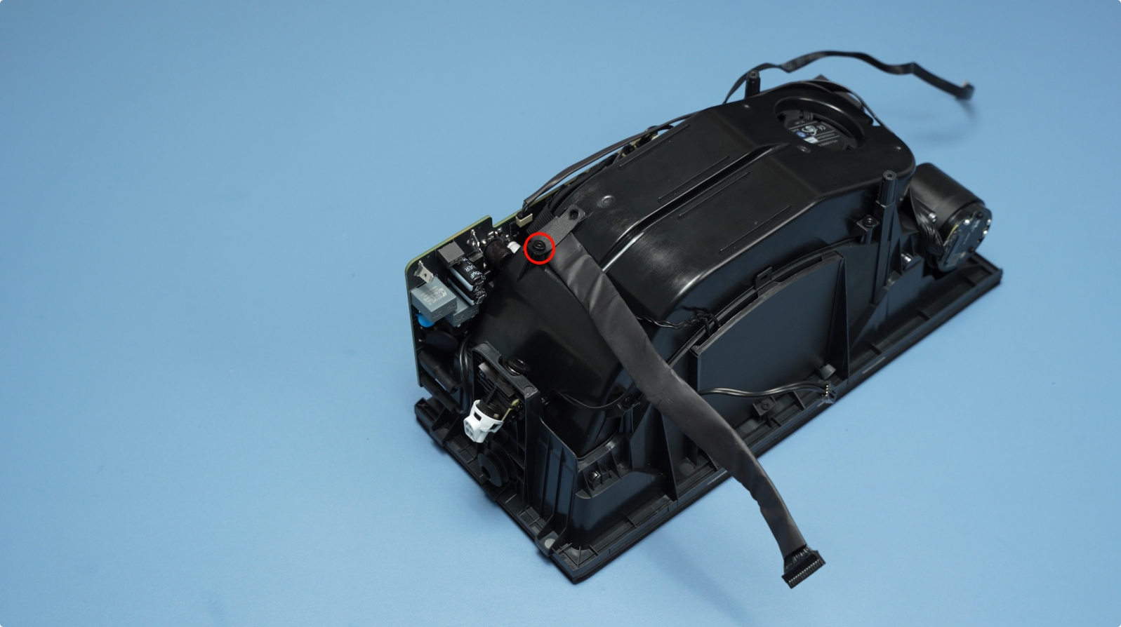
¶ Step 4: Remove the Heating Unit
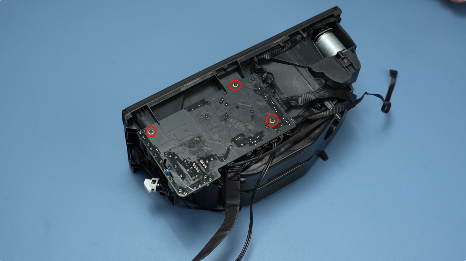
To remove the heating unit, you need to slightly move the mainboard. To do this, loosen the three mainboard screws (BT2x5) and then slide the mainboard out of its slot.
 |
 |
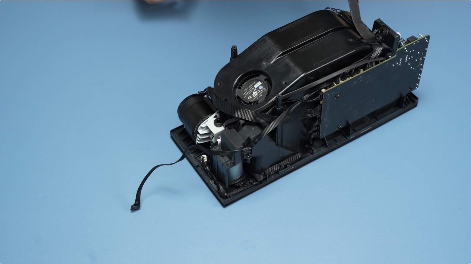
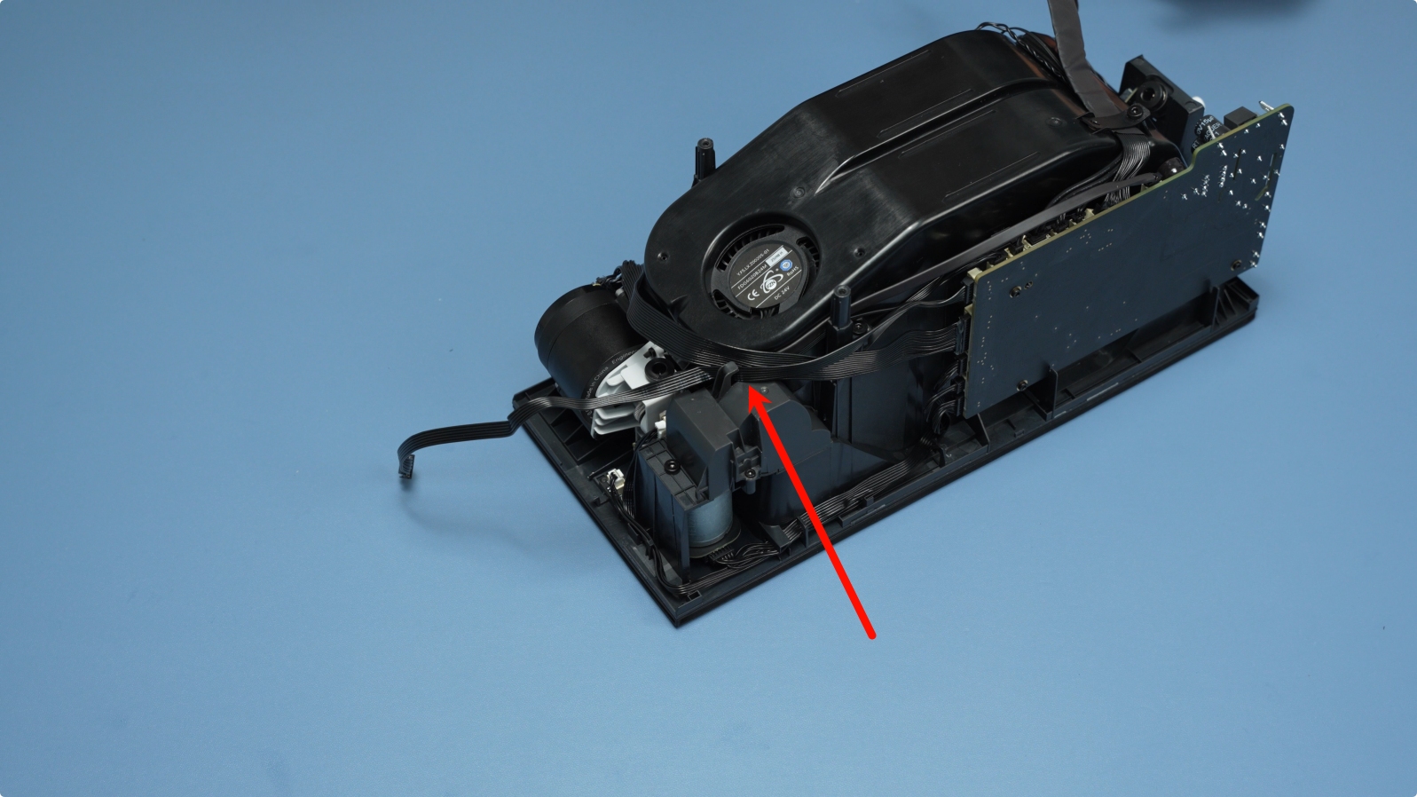
Remove the four screws securing the AMS HT heating unit, as shown in the image below.
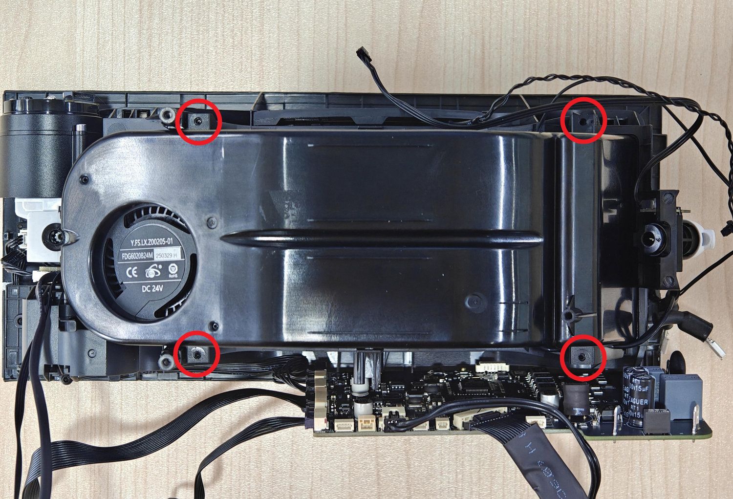
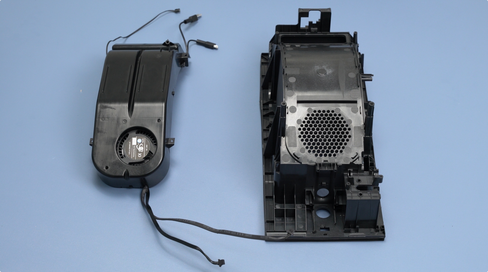
Use an H1.5 screwdriver to release the left and right fixing clips, then remove the drying component.
 |
 |
¶ Install the New AMS HT Heating Unit
¶ Step 1: Position the Heating Unit Correctly
As you begin installation, align the fan side of the new AMS HT heating unit with the ventilation holes on the middle frame, as shown below.
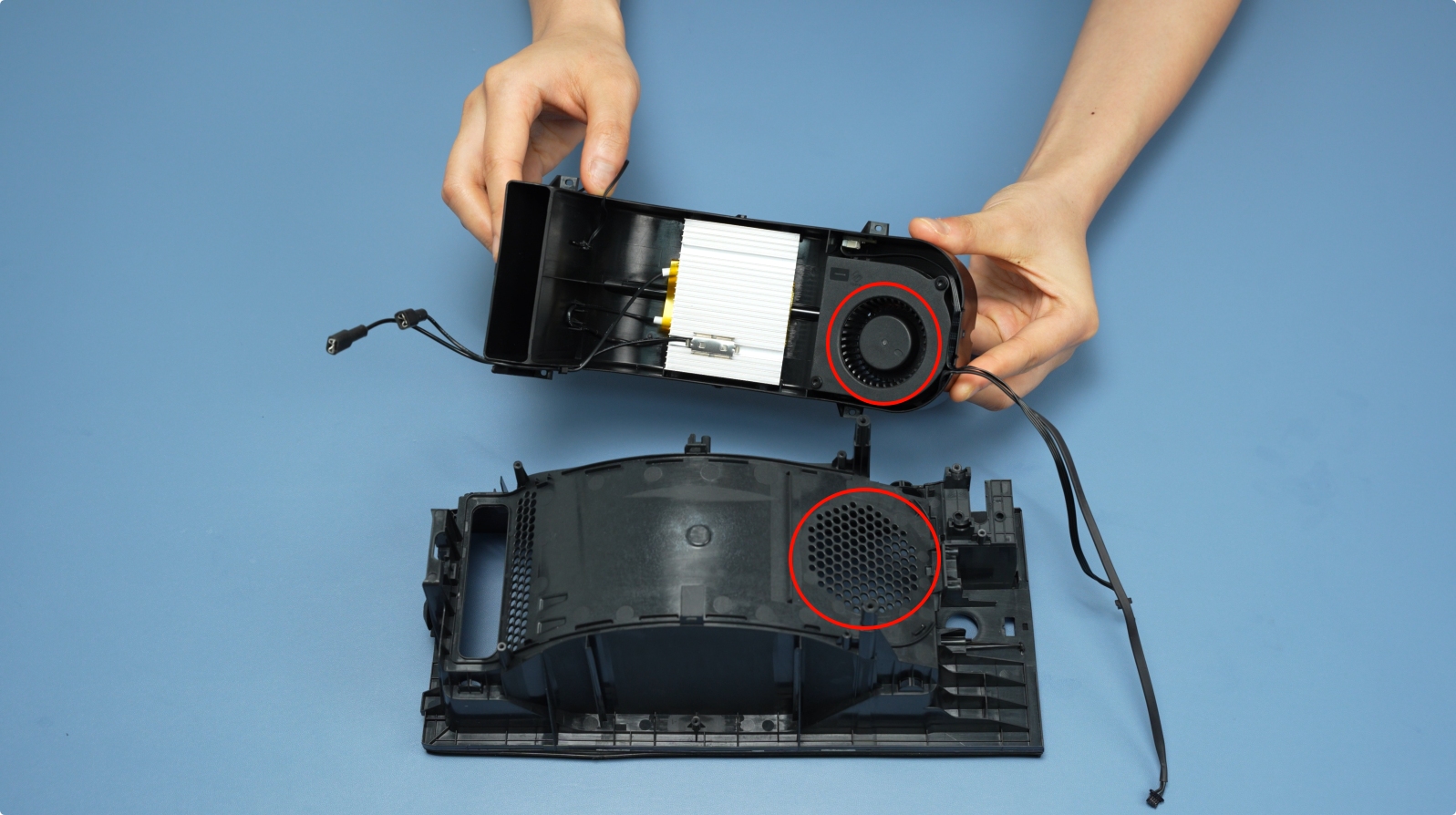
Insert the heating unit diagonally from the AMS HT filament outlet position.
Insert the four heating unit screws (BT2x6) and tighten them.

¶ Step 2: Connect the Heating Unit Cables
First, connect the heating unit cable on the mainboard side. After plugging it in, insert the insulation rubber.
Note: Polarity does not matter here.
Next, connect the five cables at the top of the mainboard. These are:
Temperature and humidity sensor
Thermistor sensor
Feeder Hall Sensor Assembly
RFID coil
Heating Unit Fan

Slide the mainboard into its slot and secure it with three BT2x5 screws.
After connecting the cables, you need to organize them. To do this, first place the four thinner cables at the bottom, then lay the thicker mainboard communication cable on top of them. Finally, install the cable retainer and secure it with a BT3x5 screw.
 |
 |
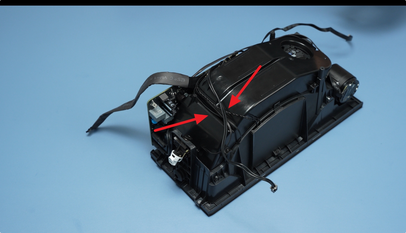
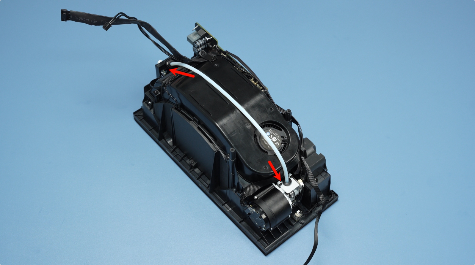
Rotate the AMS HT 180° to organize the front cables. Place the cables into the cable guide channel as shown in the images below.
 |
 |
¶ Step 3: Install the AMS HT Middle Frame
In this step, start by connecting the PTFE tube from the feeder to the outlet assembly.
Connect the cables at port 1 and 2 as shown in the image below. Port 1 is the mainboard communication cable (14-pin), and port 2 is the mainboard power cable (2-pin).
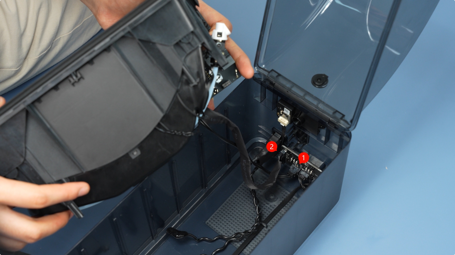
Reconnect the power socket cable to the mainboard and properly reinstall the insulation rubber sleeve.
Note: Polarity does not matter here.
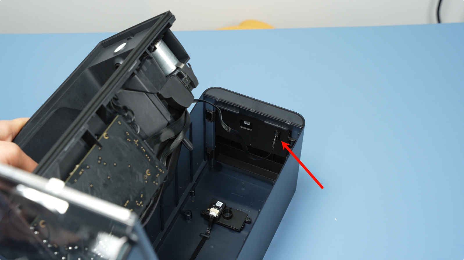
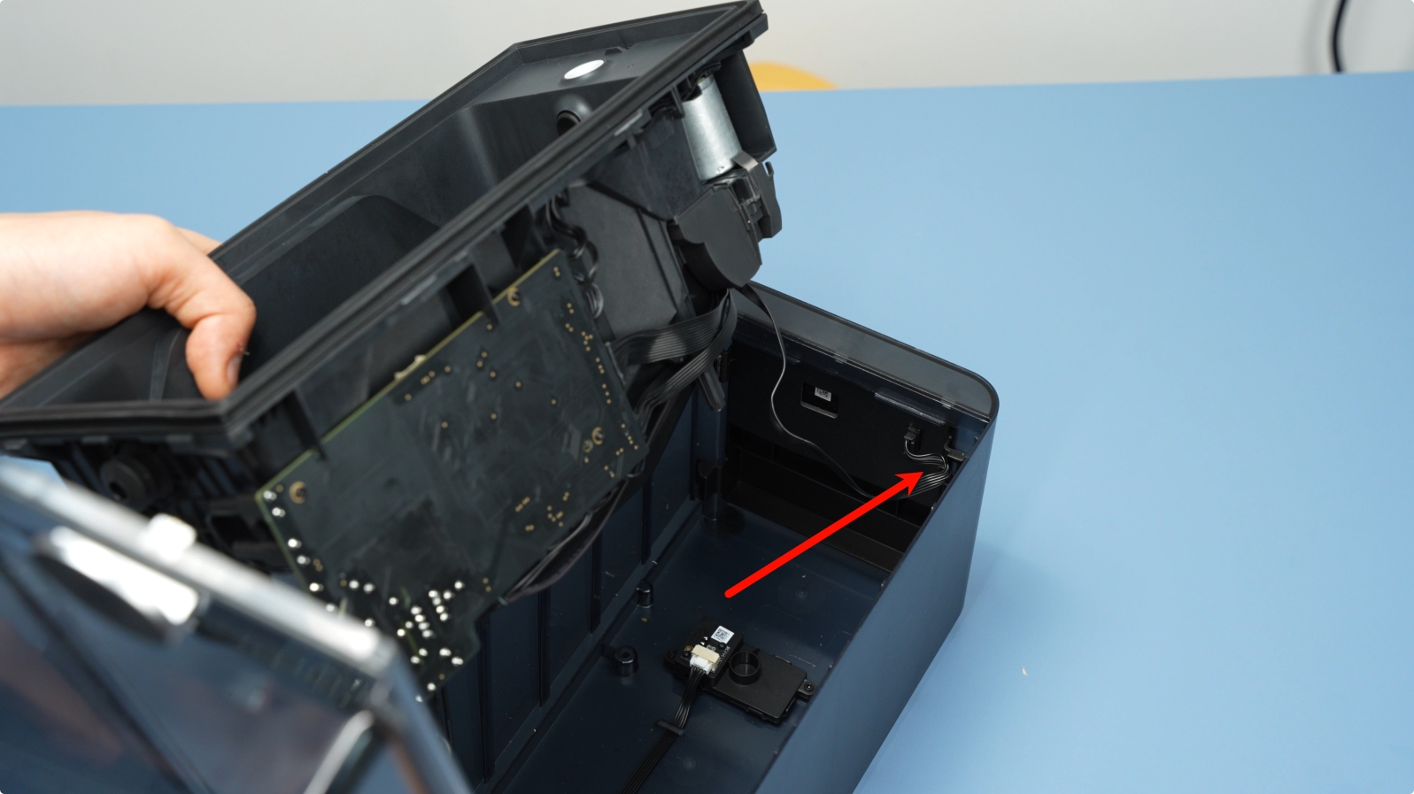
Connect the AMS HT front screen cable. After connecting, make sure to secure it is inserted into the cable routing channel.
 |
 |
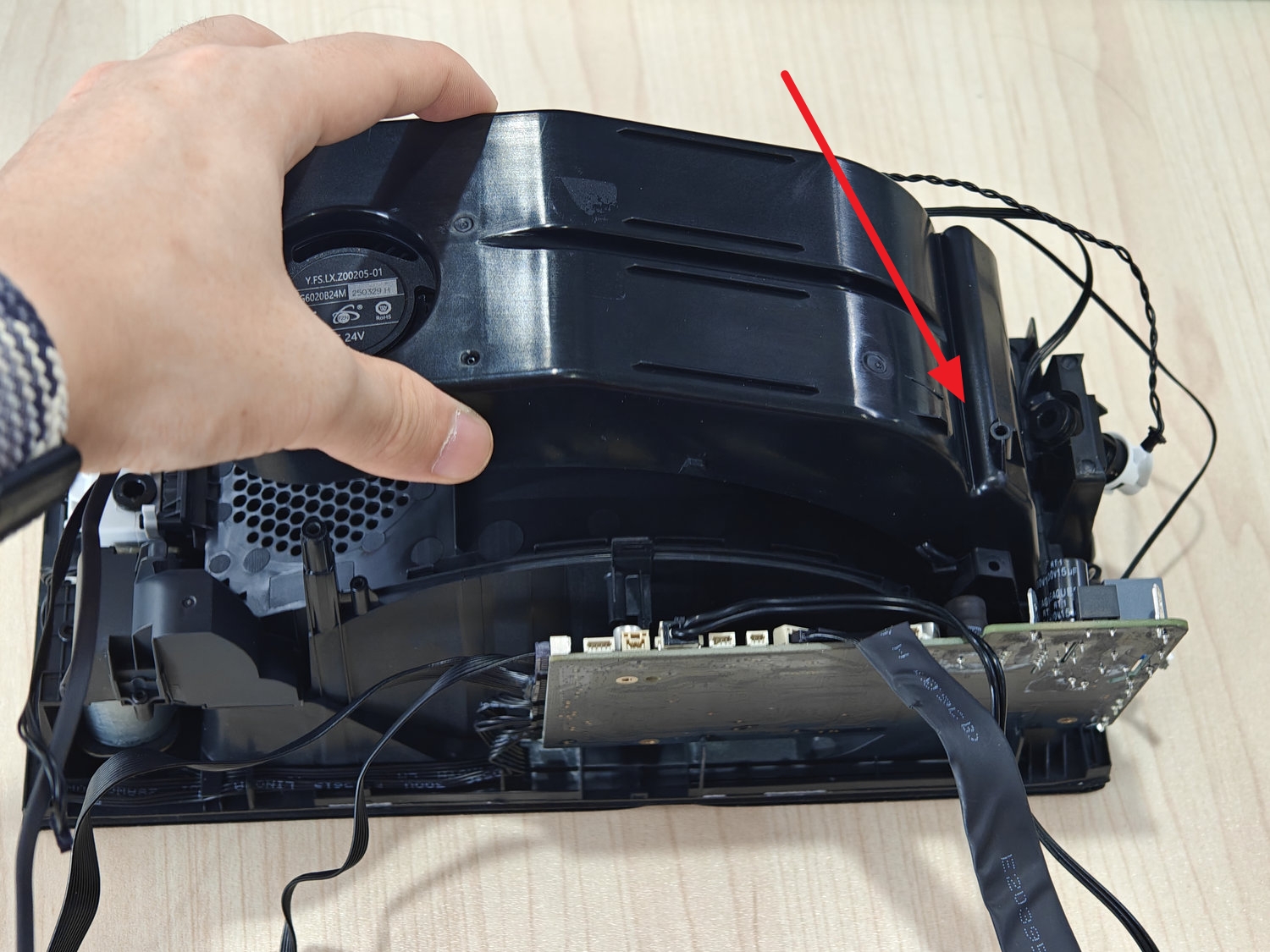
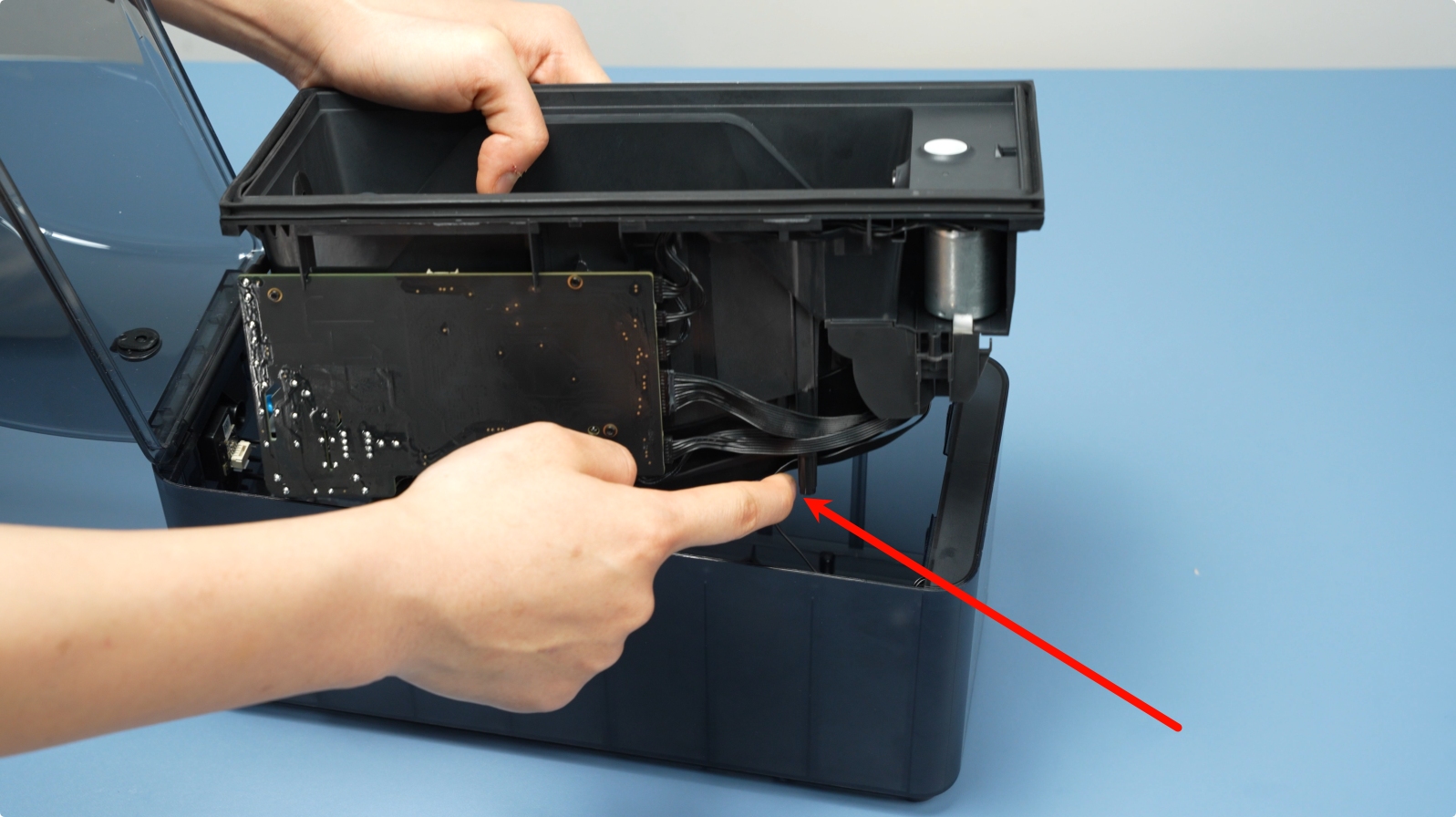
Use your finger to hook the protruding cable, then install the middle frame assembly into the bottom cover assembly.
 |
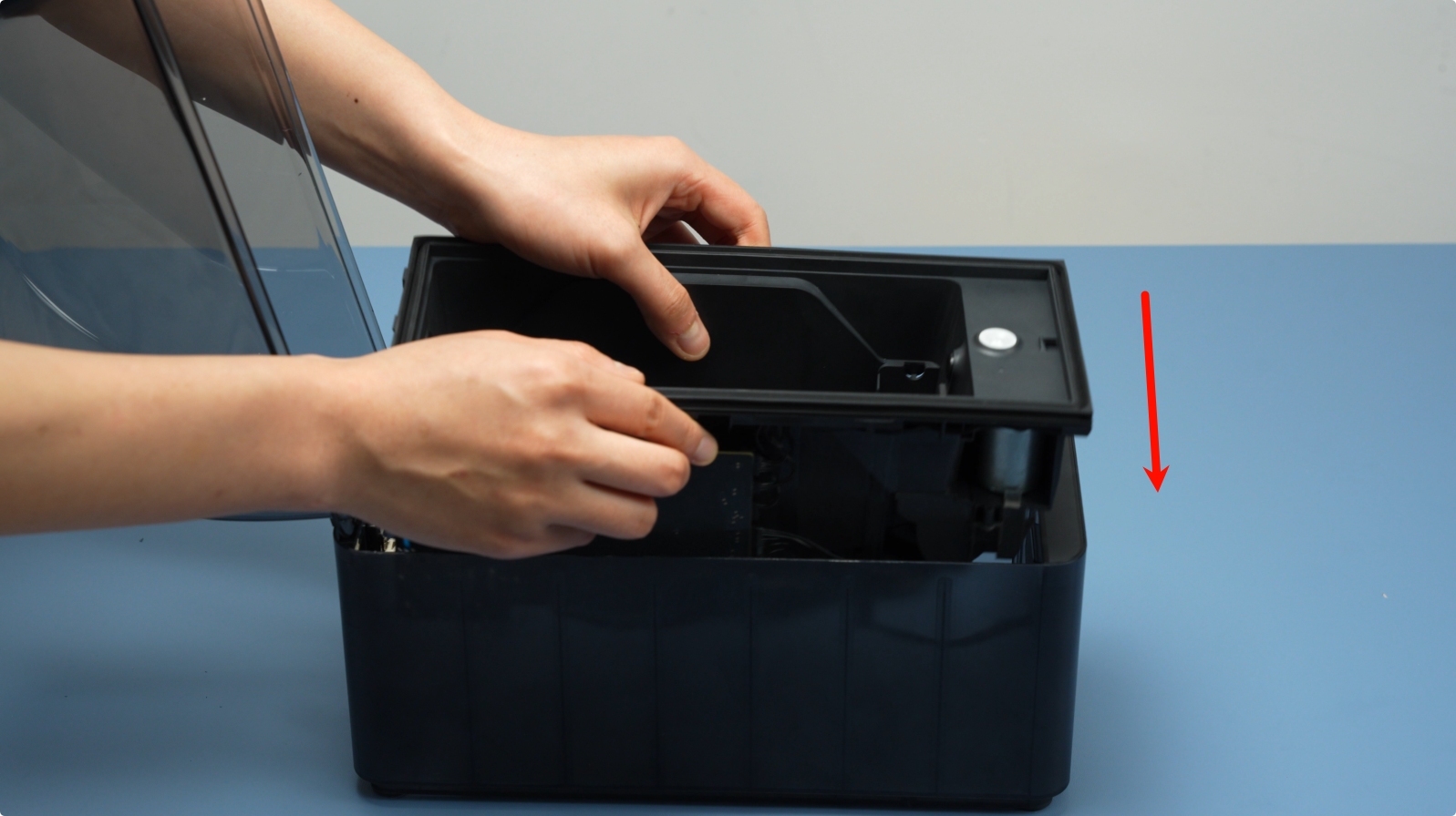 |
Make sure the middle frame assembly is fully pressed into the bottom cover assembly, with no lifting at the front or back. Then, install the two bottom mounting screws (BT3x8).
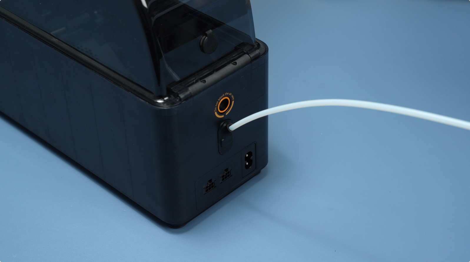
¶ Step 4: Insert the PTFE Tube Into the Back of the AMS HT.
Insert the PTFE tube into the back of the AMS HT. Once inserted, pull it slightly to confirm it is securely in place.
¶ Verify the Functionality
Ensure the power cable is properly connected, then connect the AMS HT unit to the printer. Power on the machine, and from the printer’s touchscreen, activate the drying and feeding functions of the AMS HT.
Start by testing the drying function. If it powers on correctly and the unit reaches the target temperature as expected, the drying component is functioning properly.
Next, test the feeding function. Make sure the entire loading process completes smoothly without any error messages. If both functions work as intended, the AMS HT replacement has been successfully completed.
If there are any issues, double-check all internal cable connections and try again. If problems persist, please contact Bambu Lab’s customer support team for further assistance.
¶ End Notes
We hope our guide was helpful. If you have any questions or concerns about the process, please contact our customer service team. We're here to assist you.
Click here to open a new ticket in our Support Page.
We will do our best to respond promptly and provide you with the assistance you need.