¶ Introduction to each module
This guide introduces each module of the AMS HT, explaining its parts, connections, and functions. It also covers installation, setup, and multi-unit connection methods to help users correctly configure their AMS HT for optimal performance.
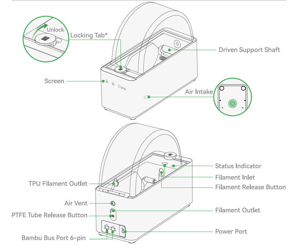
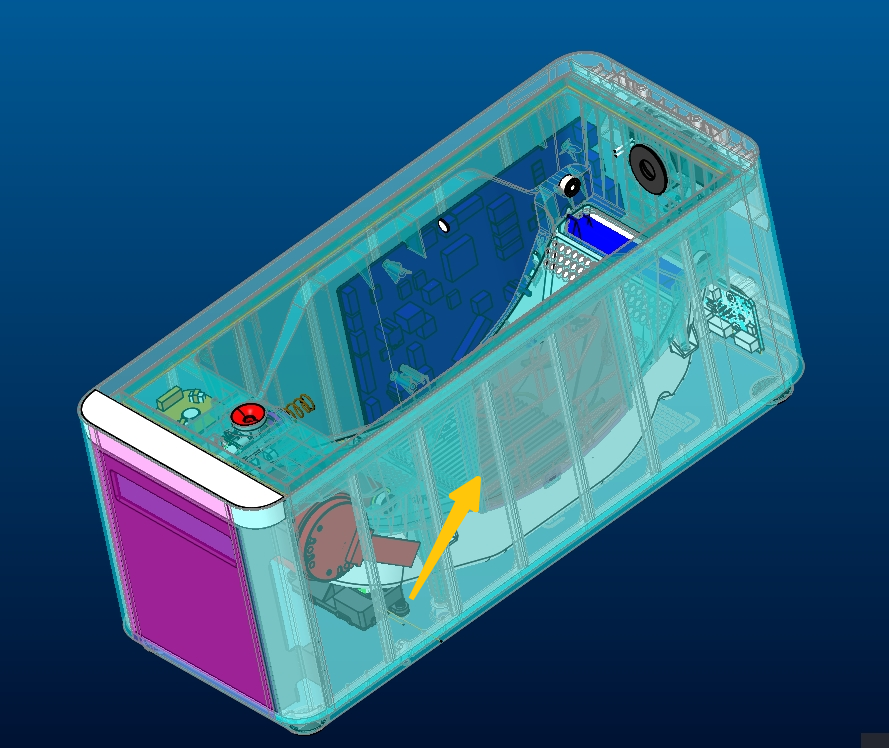
¶ Appearance and 3D dimension diagram
| The appearance of AMS HT | Component schematic diagram |
|---|---|
 |
 |
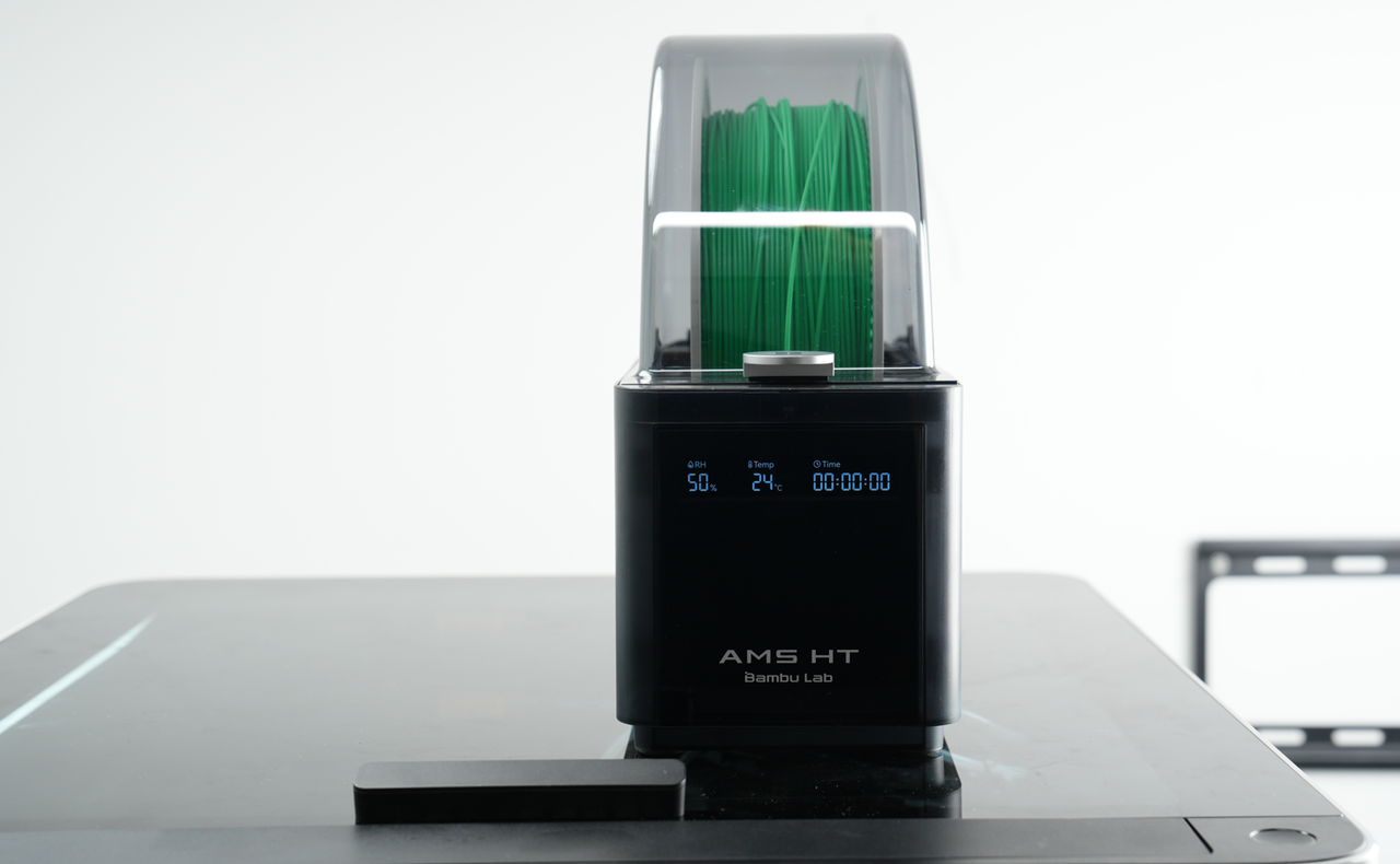
¶ AMS HT Display
The front of the AMS HT has a display showing real-time humidity, temperature, and remaining drying duration from left to right, as shown in the image below.

¶ Lid Open Sensor
The AMS HT is equipped with a lid-open sensor consisting of a magnet and a Hall sensor. If the lid is opened during the drying process, the printer will issue a reminder. The magnet is located on the lid handle assembly, while the Hall sensor is positioned on the middle frame.
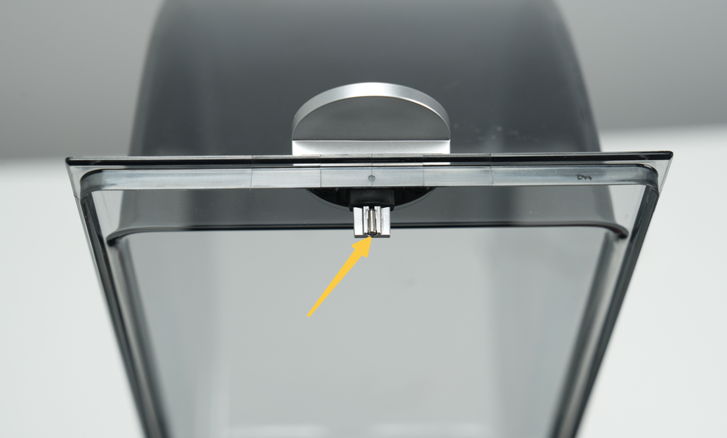 Magnet |
 Hall sensor |
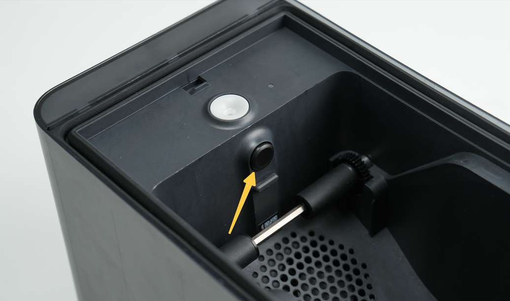
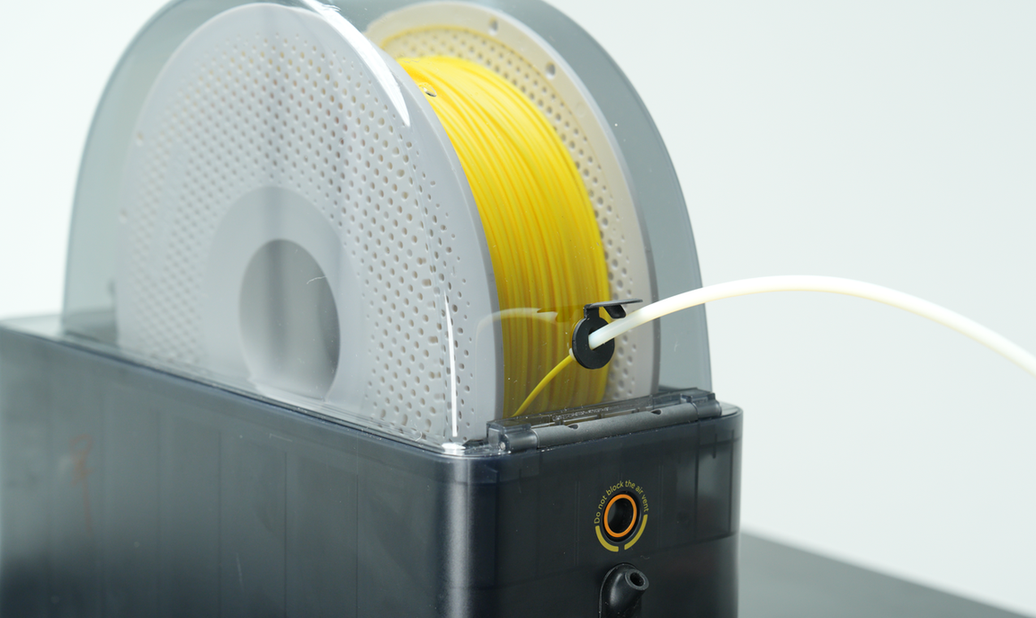
¶ Filament Inlet and Indicator Light
The filament inlet of the AMS HT is shown in the image below. When a filament is inserted, the inlet automatically pulls it in. When retracting the filament, the active shaft rotates the spool to wind it back. The inlet is embedded with a ceramic-reinforced anti-wear sleeve to effectively prevent wear caused by prolonged use.
Next to the inlet is an indicator light, with different light patterns corresponding to various AMS HT operating modes.
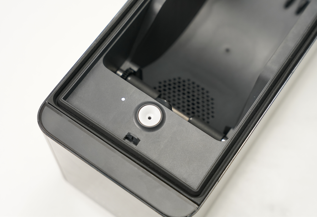
¶ Filament Release Button
Behind the filament inlet is a filament release button. When the filament is inside the AMS and needs to be manually removed, pressing this button releases the gear pressure, allowing the filament to be easily pulled out.
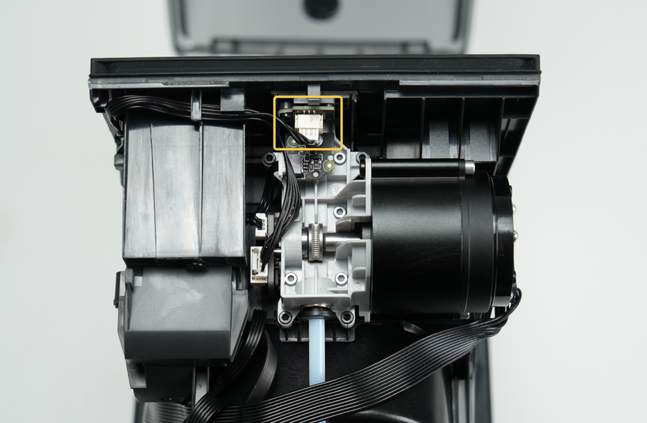
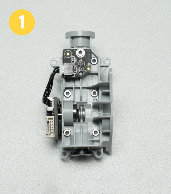
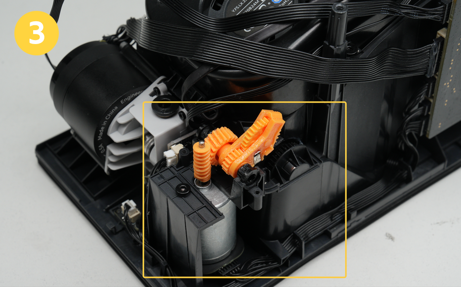
¶ Internal hub
The internal hub unit is located at the head of the AMS HT and consists of a feeder unit, an internal assist motor, and a filament retraction assembly.
-
Feeder Unit:
Includes a filament detection sensor and an odometer wheel. The Hall sensor detects whether the filament is inserted, and the odometer wheel calculates the feeding length. -
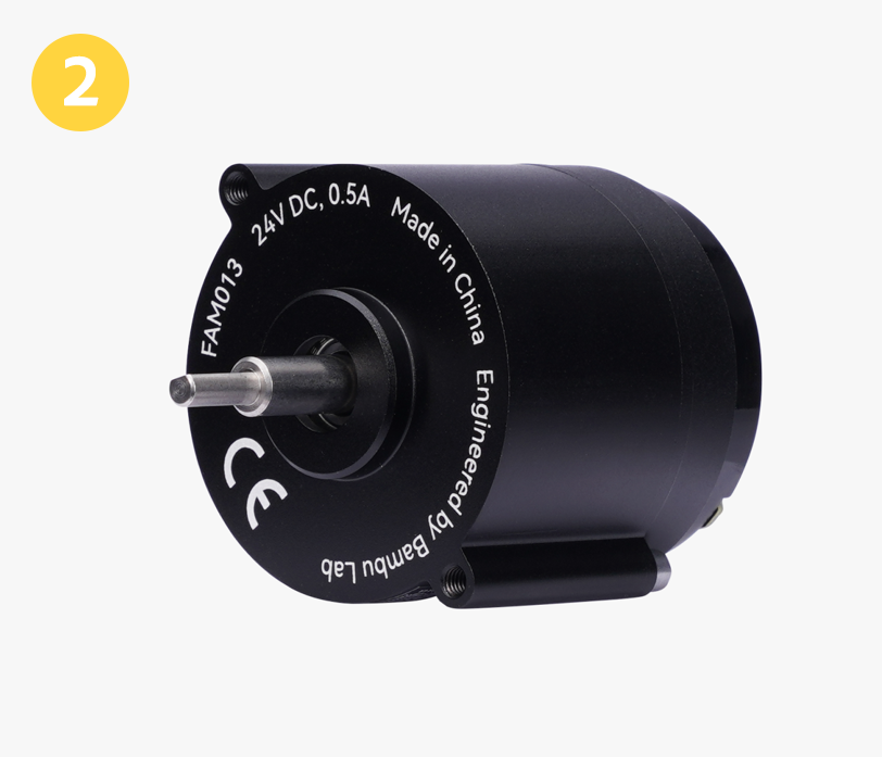
Internal Assist Motor:
Drives the feeding and unloading of the filament. This motor provides torque to move filament in or out smoothly. -
Filament Retraction Assembly:
Includes a motor and rocker gear. It drives the active shaft to rotate during unloading, winding the filament back onto the spool.
 |
 |
 |
 |
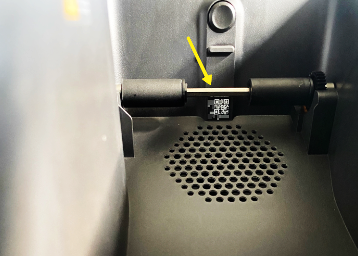
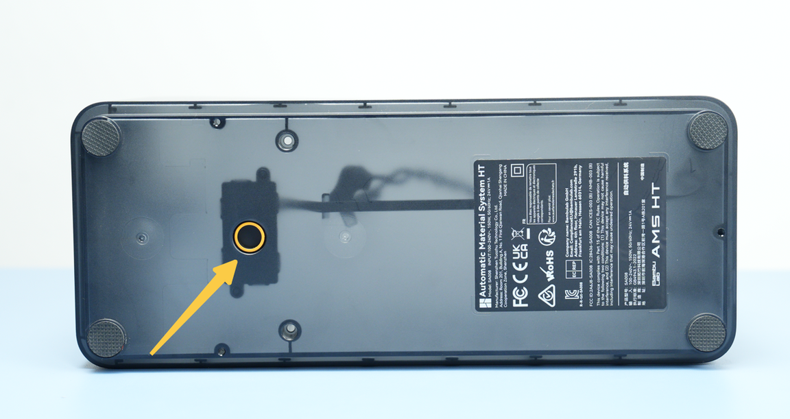
¶ Serial Number
The AMS HT serial number sticker is located at the front of the unit, directly beneath the filament roller bar inside.
- The Serial Number contains both an alphanumeric serial number and a QR code.
- Use this Serial Number for warranty and support requests.
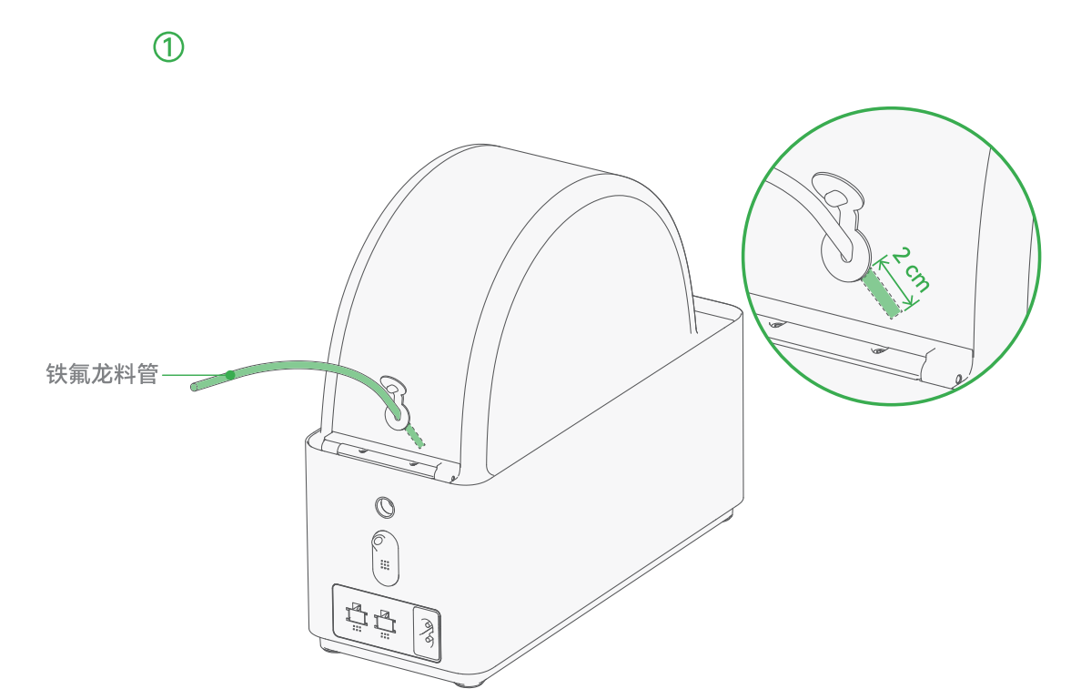
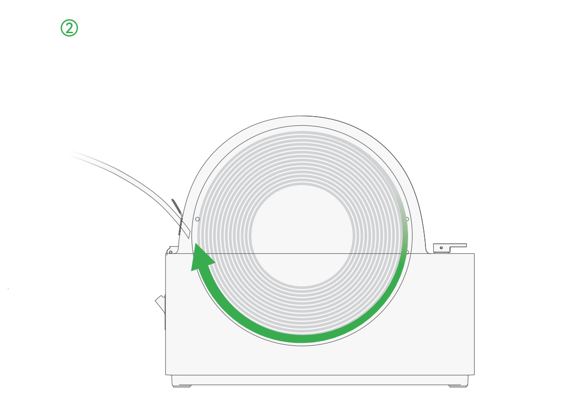
¶ TPU Outlet
The AMS HT has a dedicated TPU outlet at the rear of the lid. Due to the soft nature of the TPU filament, automatic feeding through the AMS often fails. When using TPU, place it in the AMS HT, ensure the spool rotates in the correct direction, and insert the PTFE tube into the TPU outlet. Manually push the filament through the PTFE tube into the extruder until the gears fully engage it.
Note: When using TPU, the AMS HT cannot utilize automatic feeding and unloading functions but can still serve as a drying box to prevent moisture absorption.
 |
 |
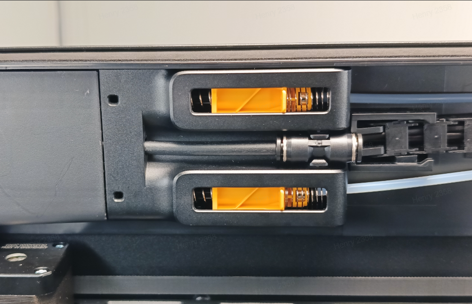
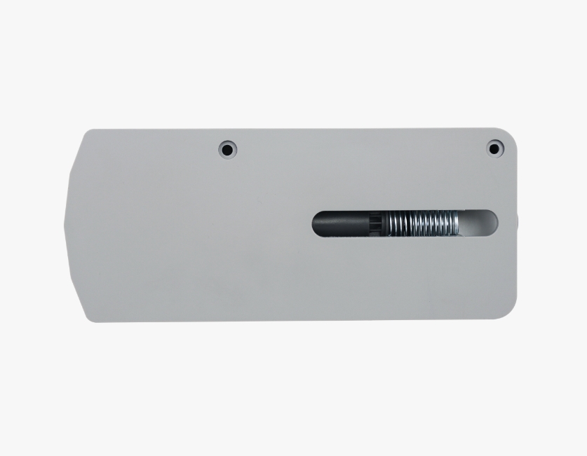
¶ Outlet and Release Button
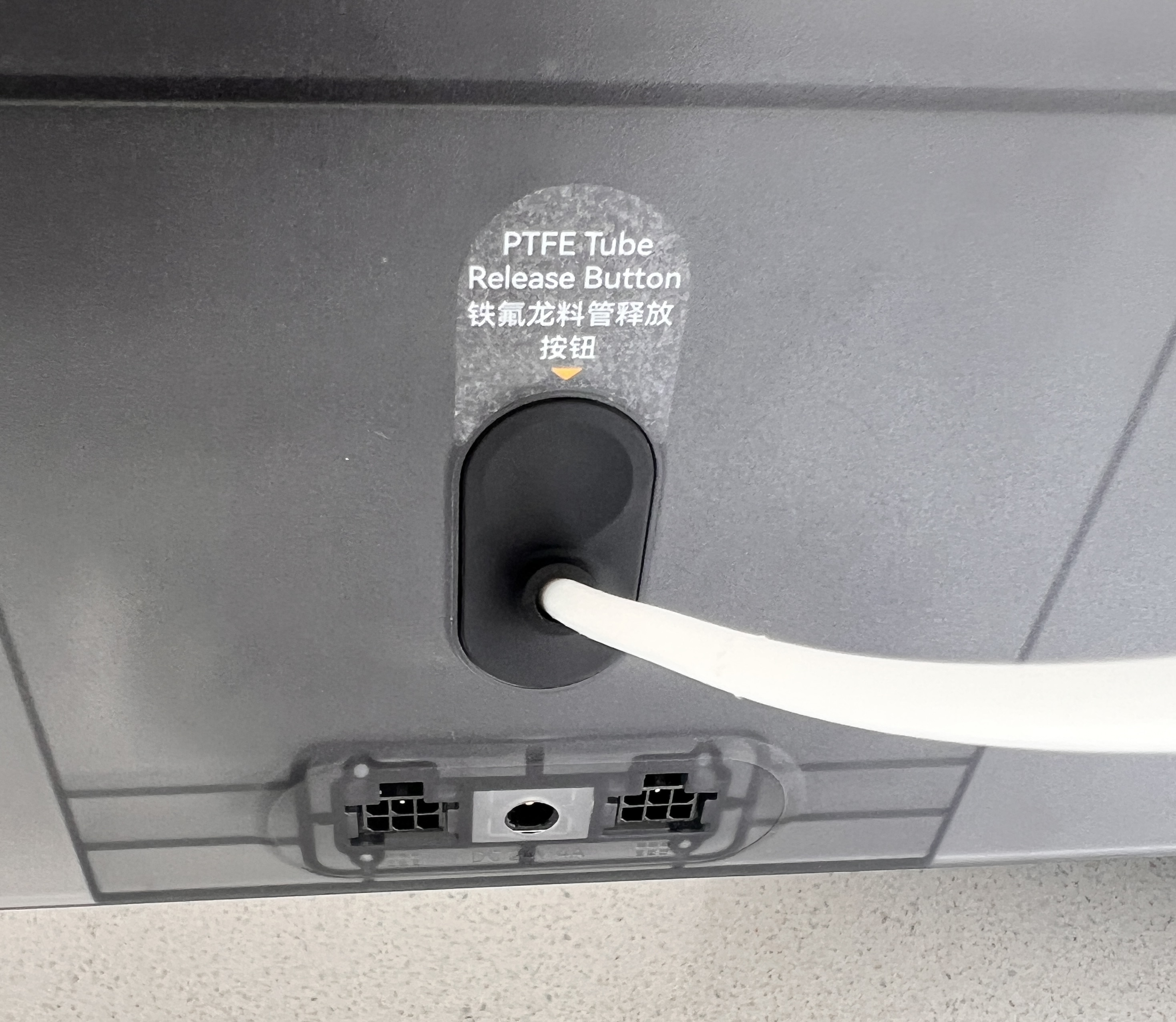
The rear of the AMS HT features an outlet for connecting PTFE tubes, with a square release button below it. Pressing the button releases the tube for easy removal.
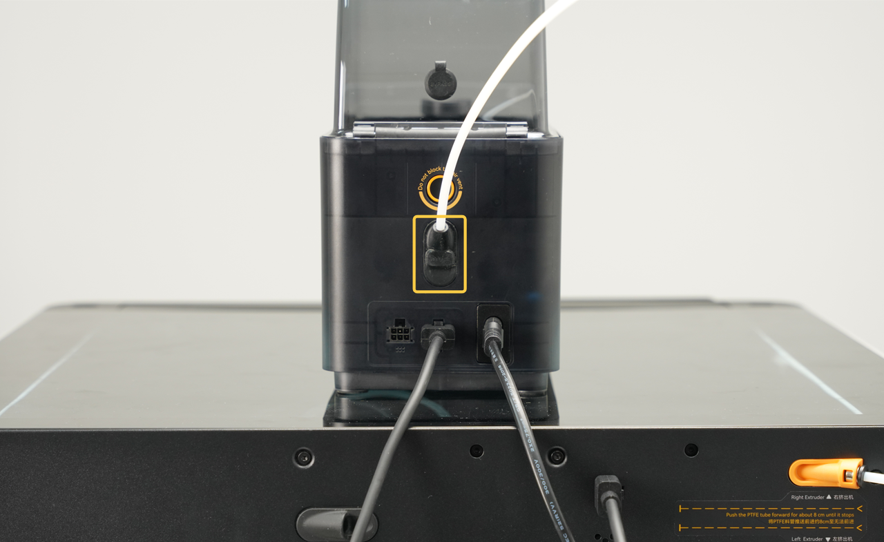
¶ Outlet Hall Sensor
Near the outlet at the rear of the AMS HT is an outlet Hall sensor. This component detects whether the filament has been successfully fed out of the AMS. In cases of filament breakage or jamming, the outlet Hall sensor helps locate the filament for quick troubleshooting.
|
 |
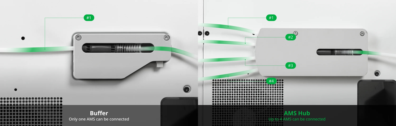
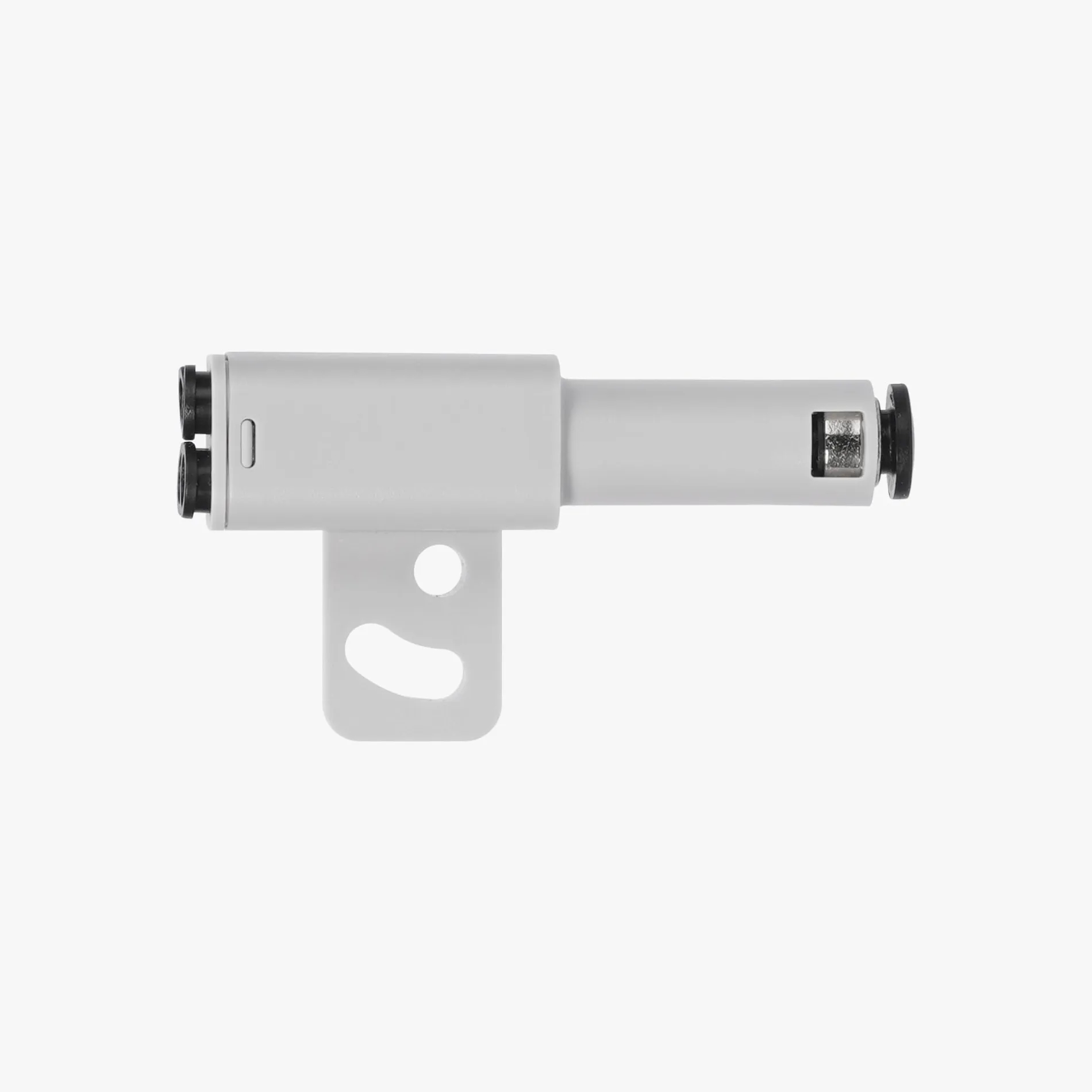
¶ Buffer
The AMS HT and printer need to be connected via a buffer, which consists of a slider, a spring, and a Hall sensor.
When the AMS pushes the filament into the extruder, the slider moves forward due to the pressure of the filament. The Hall sensor detects the slider's position, and the buffer sends the signal back to the AMS and the printer. By controlling the feeding speed of the AMS, the tension of the filament can be kept within a controlled range, allowing the extruder to work smoothly and precisely.
The H2D printer comes with a built-in feeding buffer, which also includes a filament sensor inside. This sensor can detect whether the filament is passing through the buffer or if the filament has broken inside the buffer. Additionally, when printing with an external spool, the buffer also features a tangle detection function, which can detect whether the external spool has tangled filament.
To connect the AMS HT to X1 or P1 series printers, an additional buffer (for one unit) or an AMS Hub (for multiple units) is required.
Important:
Combo printers (sold with an AMS) include one Buffer by default.
If the printer was purchased without an AMS, an additional buffer is required to connect the AMS HT.
¶ Moisture Prevention System
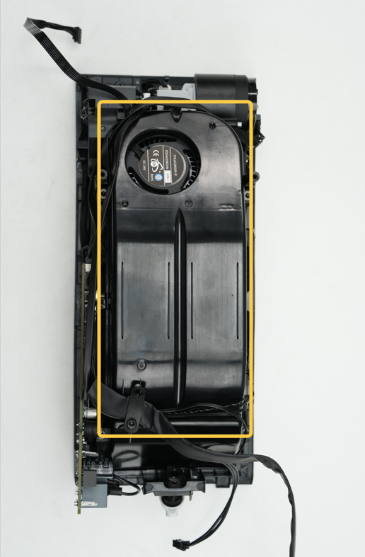
¶ Drying Module
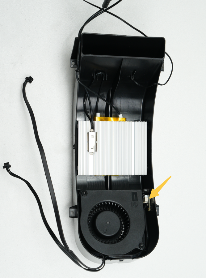
The drying module in the AMS HT consists of a heater, a fan, and an NTC temperature sensor, with a maximum drying temperature of 85°C.
 |
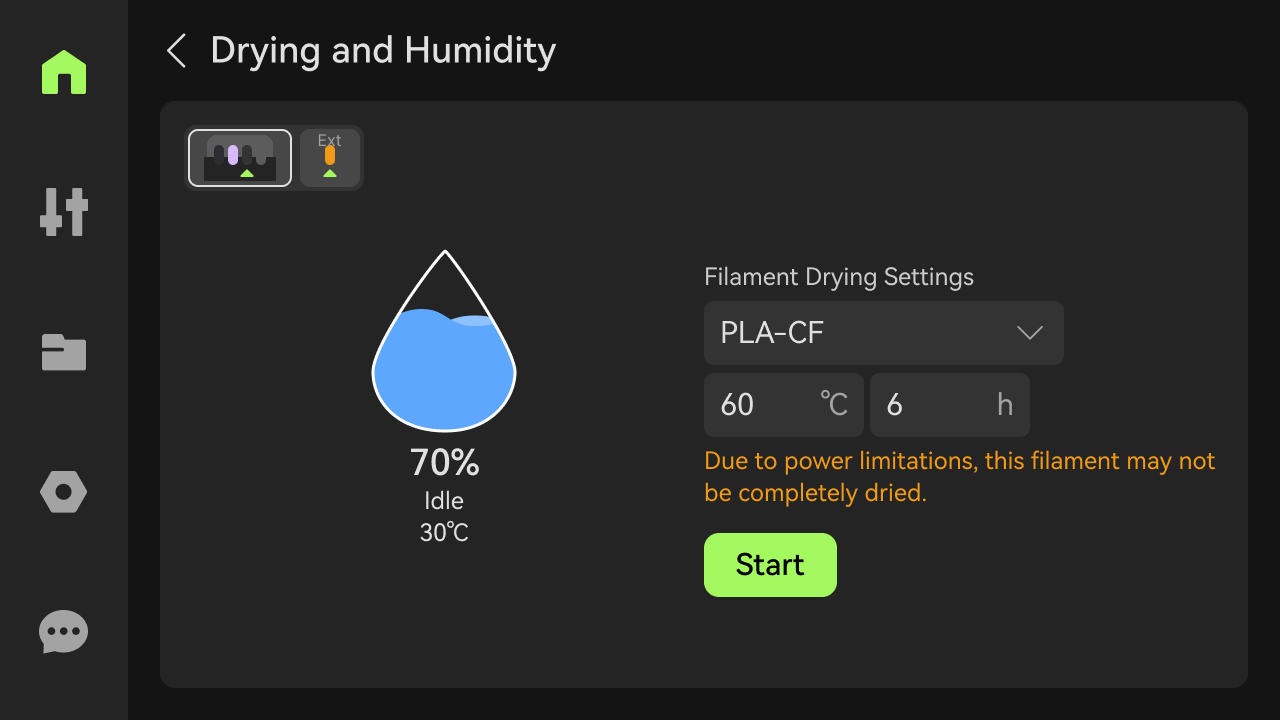 |
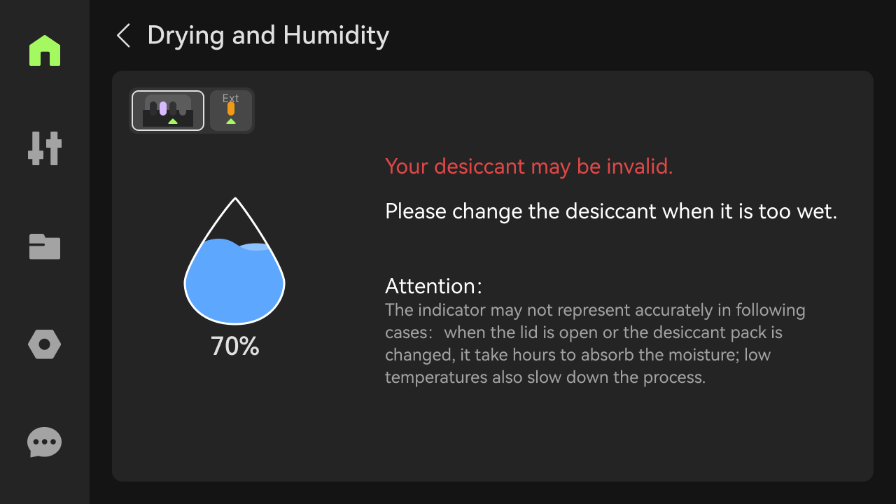
¶ Humidity Sensor
The AMS HT is equipped with a humidity sensor located inside the drying module, which monitors the internal humidity and temperature. You can check the current humidity status on the printer's display, Bambu Studio, or Bambu Handy.
 |
 |
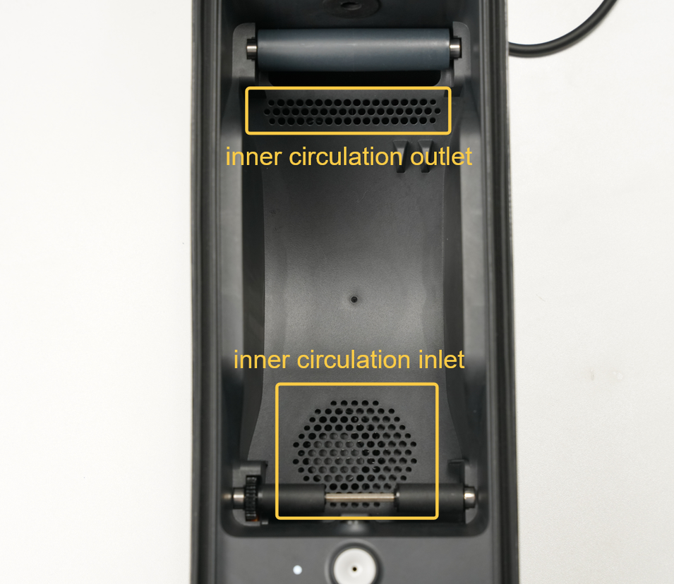
¶ Internal Circulation System
The drying module is located below the main frame of the AMS HT. During drying, hot air is blown out from the internal circulation inlet (near the filament inlet), heats the filament, and is then drawn back into the heating module through the rear internal circulation outlet, forming an internal circulation system.
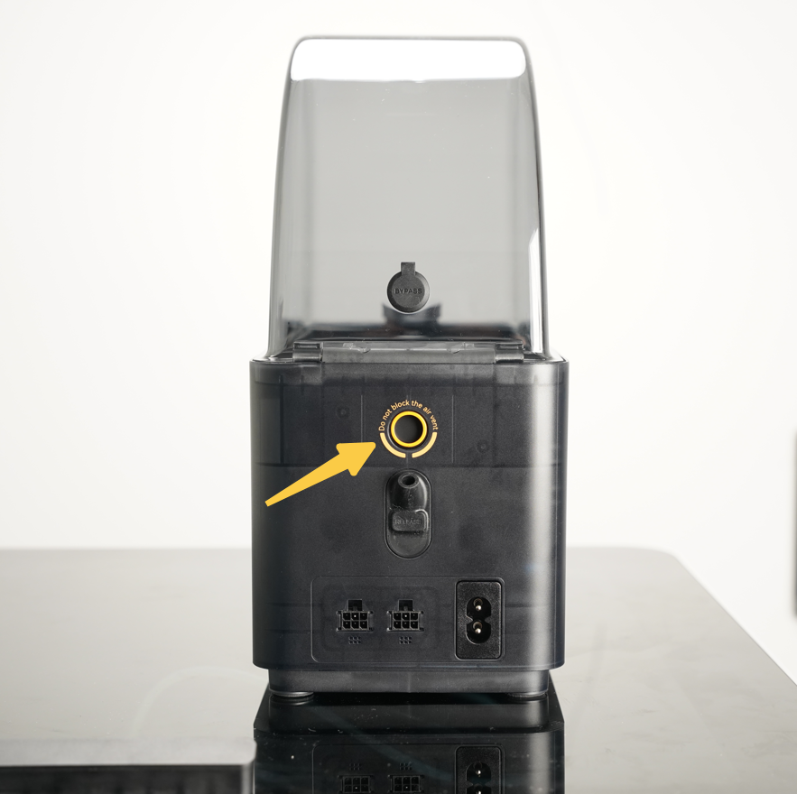
¶ Air Vents
The AMS HT is equipped with two actively controlled air vents: the bottom vent is the intake, and the rear vent is the exhaust.
During drying, the AMS HT expels moisture through external circulation. Ensure the vents are not blocked for optimal drying performance.
 |
 |
|---|
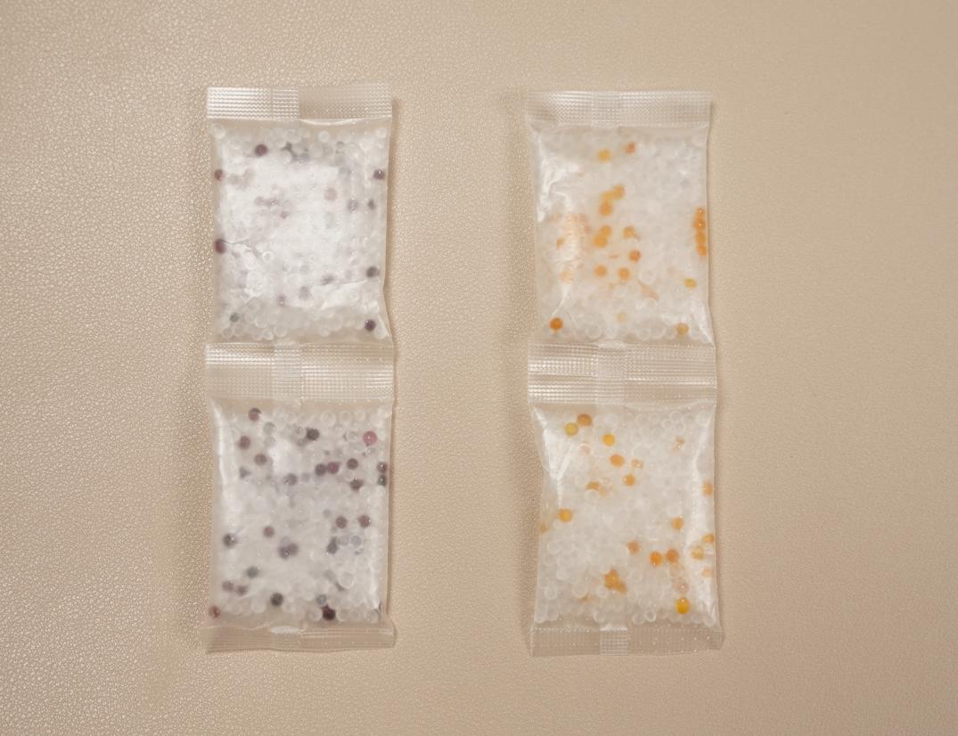
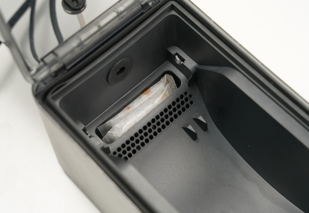
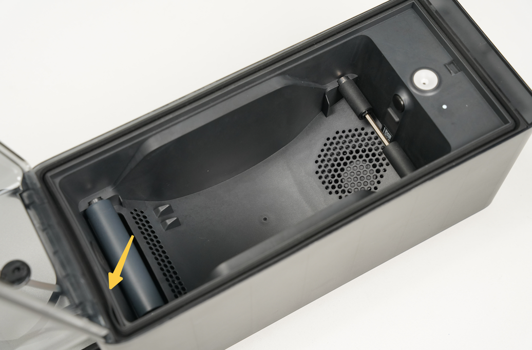
¶ Desiccant and Sealing Rubber
The AMS HT comes with a color-changing silica gel desiccant, located below the rear driven shaft. The desiccant absorbs moisture to maintain dry air inside the chamber. When the yellow particles turn dark green, the desiccant needs to be replaced or dried for reuse.
A rubber sealing gasket between the lid and the housing ensures the AMS remains airtight, preventing external moisture from entering. If humidity exceeds the preset threshold, the humidity sensor will alert the user.
| Desiccant status | Desiccant location | Rubber sealing gasket |
|---|---|---|
 |
 |
 |
Note: The desiccant must be removed from its sealed plastic transparent bag before being placed into the AMS HT. Keep the inner bag intact, as it is designed to allow moisture absorbtion.
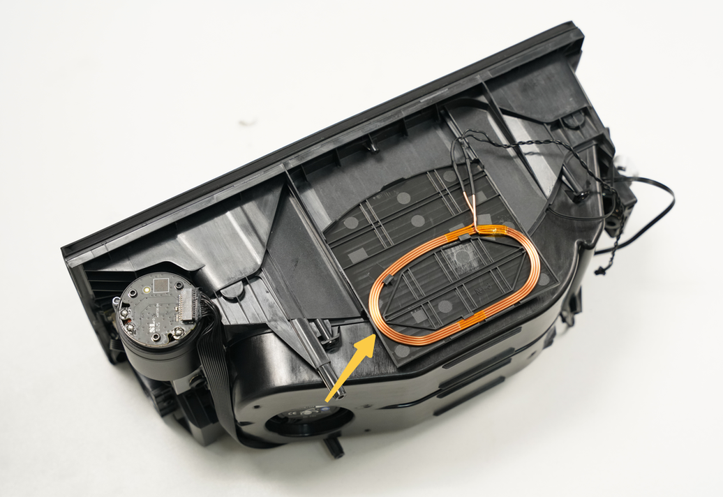
¶ RFID Module
The AMS HT is equipped with an RFID coil that can recognize RFID tags on Bambu Lab official filaments, enabling features such as filament remaining estimation and automatic refilling.
 |
 |
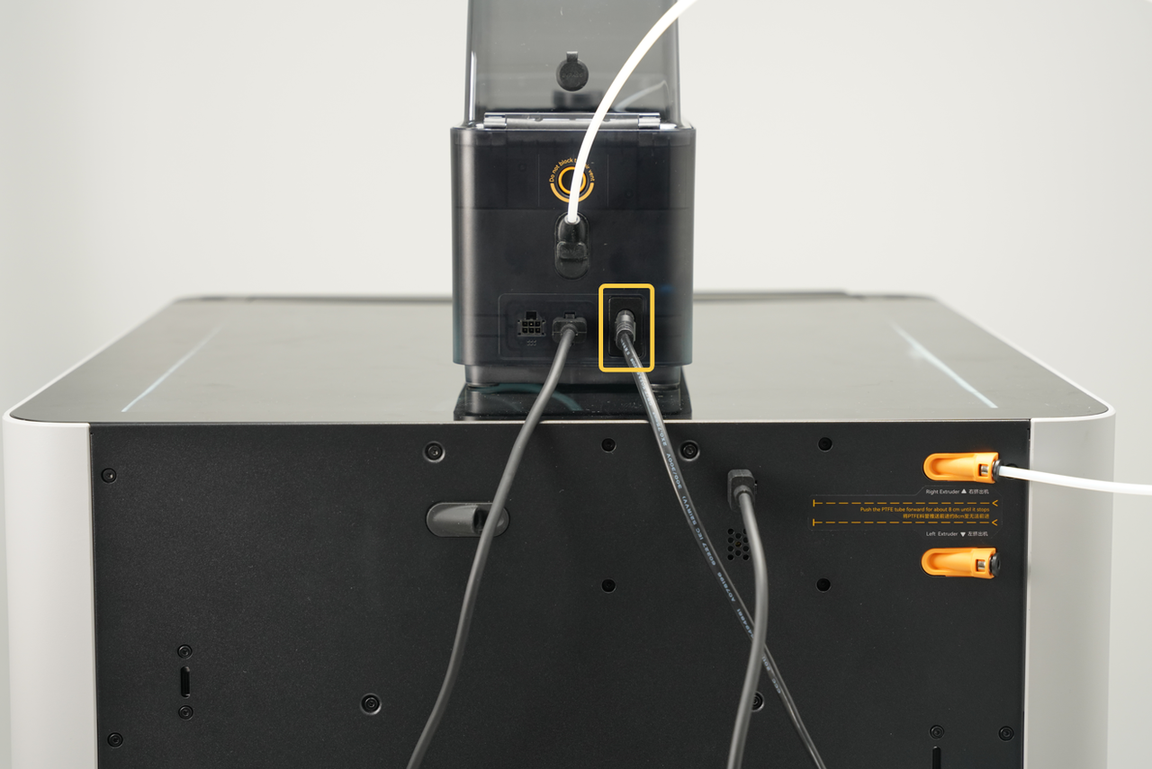
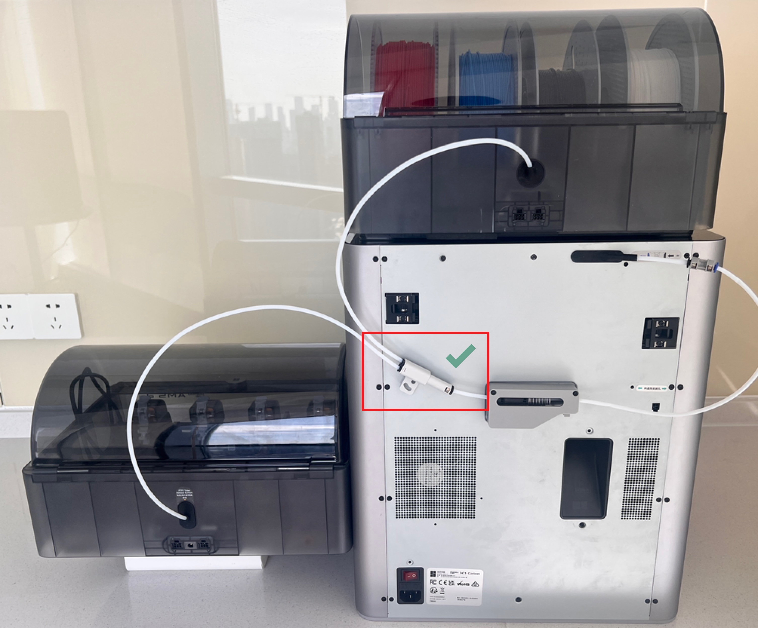
¶ Power Cable
Due to the high power requirements of the AMS HT drying function, it cannot be powered directly by the printer. Therefore, the AMS HT comes with a power cable, which must be connected to use the drying function. The connection method is shown in the image below.
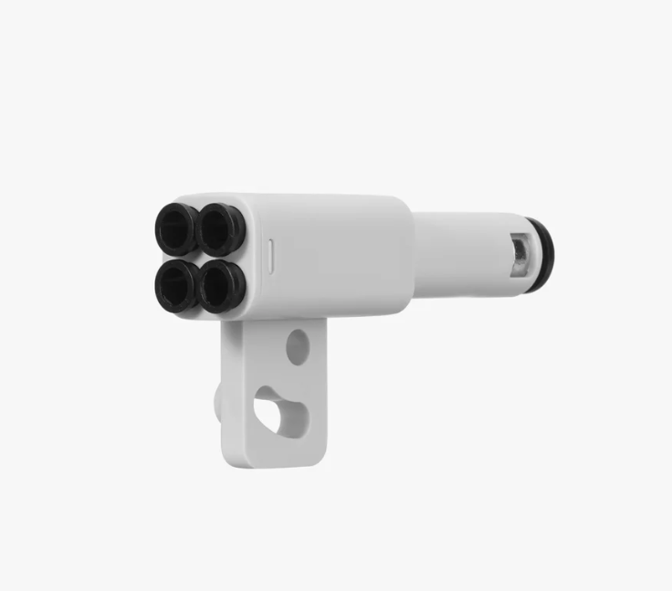
¶ PTFE adapter
The PTFE tube can connect 4 feed tubes to the printer at the same time. When connecting multiple AMS HT to H2 series printers, the PTFE adapter is required.
¶ Connecting and Configuring the AMS HT
¶ Connecting AMS HT to H2 Series Printers
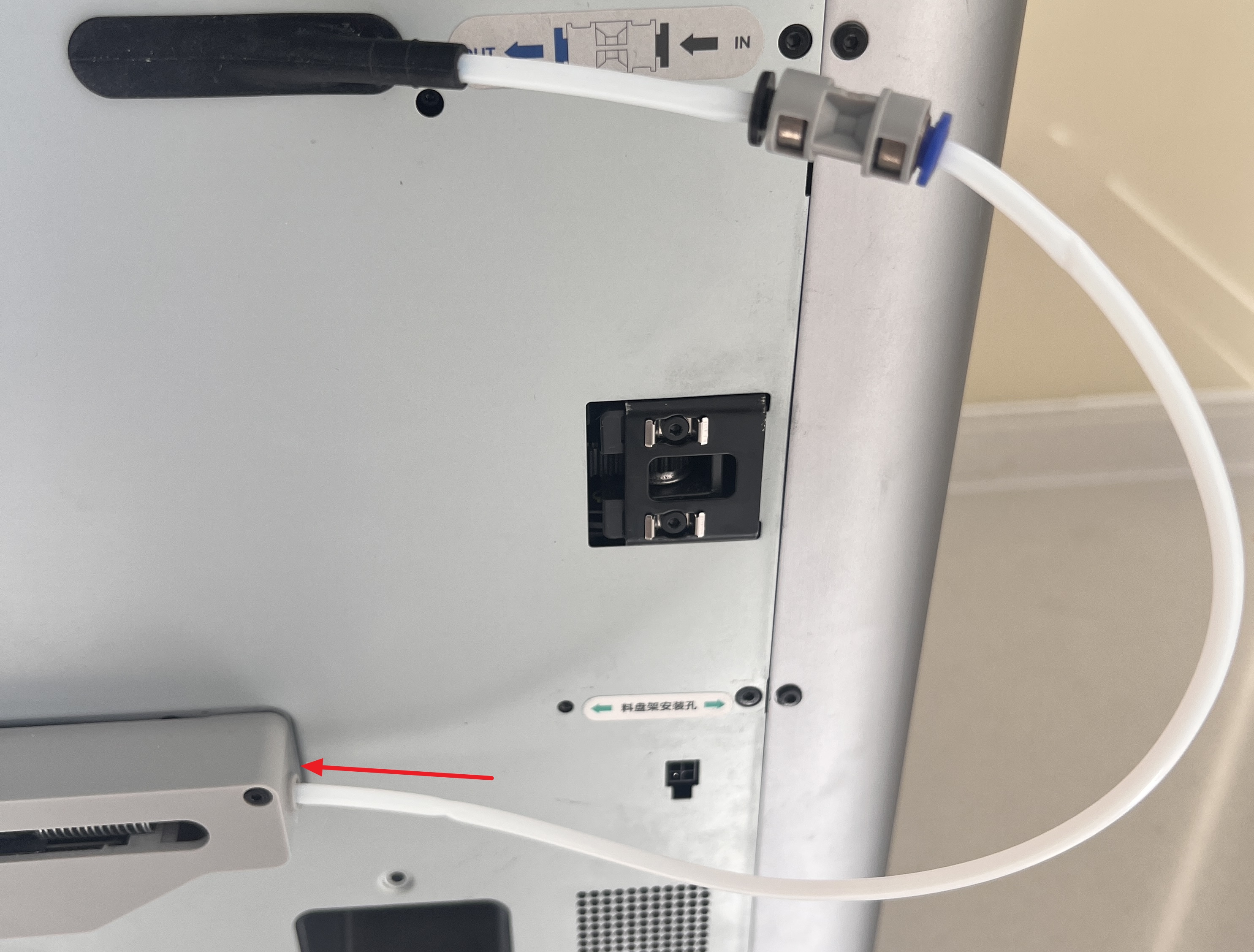
The original feeding buffer of H2 series printers can only connect 2 AMS HT units. With the tube expansion port, H2 series printers can support up to 8 AMS HT units.
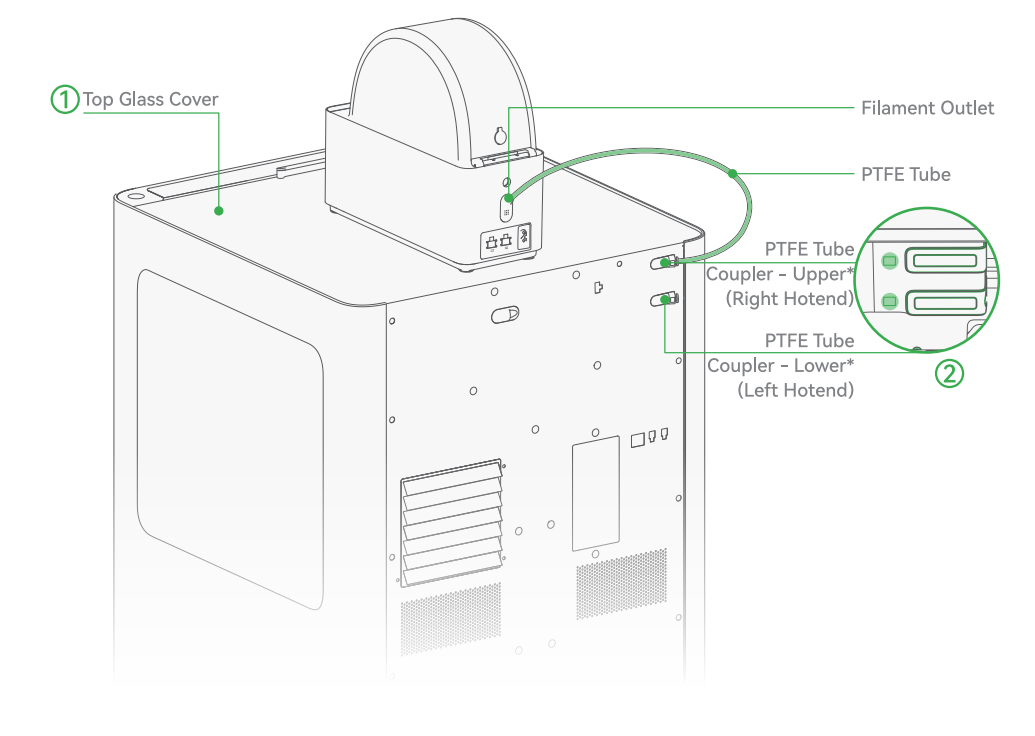
- Place the glass lid and AMS HT on top of the printer.
Take the PTFE tube from the accessory box, insert one end into the AMS HT outlet, and the other end into any printer inlet. Push the PTFE tube forward until it stops, approximately 10 cm (when observing the window next to the buffer from the front of the printer, if the PTFE tube is visible, it is properly inserted). The upper and lower inlets correspond to different hotends: connecting the AMS HT tube to the upper inlet enables multi-color printing with the right hotend, while connecting to the lower inlet enables multi-color printing with the left hotend.
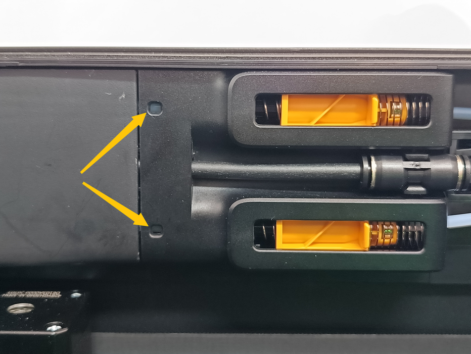
Ensure the PTFE tube is visible through this window.
| Connect PTFE tubes | Make sure you can see the tube in this window |
|---|---|
 |
 |
- Take the 6-pin cable from the accessory box and connect one end to the printer and the other end to any 6-pin port on the AMS HT, as shown in the image below. If using the drying function, connect the power cable to the AMS HT power port.
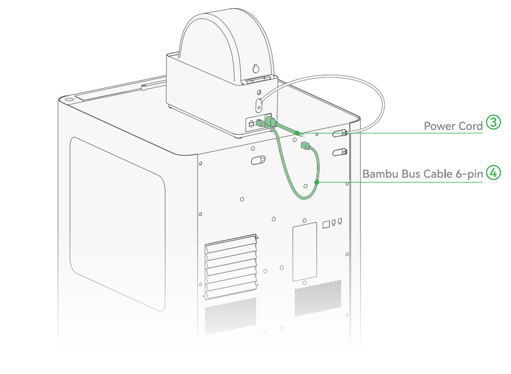
Note: Be sure to use the new 6-pin cable included with AMS 2 Pro and AMS HT. Using the 6-pin cable from the previous generation AMS may cause unstable communication between the AMS and the printer, while the previous generation AMS is compatible with the new 6-pin cable.
¶ Connecting AMS HT to X1 and P1 Series Printers
X1 and P1 series printers support up to 4 AMS HT units simultaneously.
- Place the glass lid and AMS HT on top of the printer.
Secure the buffer to the printer using 2 M3*21.5 screws. Insert one end of the 550 mm PTFE tube into the AMS HT outlet and the other end into the left side of the buffer. Insert one end of the 370 mm PTFE tube into the printer's inlet and the other end into the right side of the buffer.
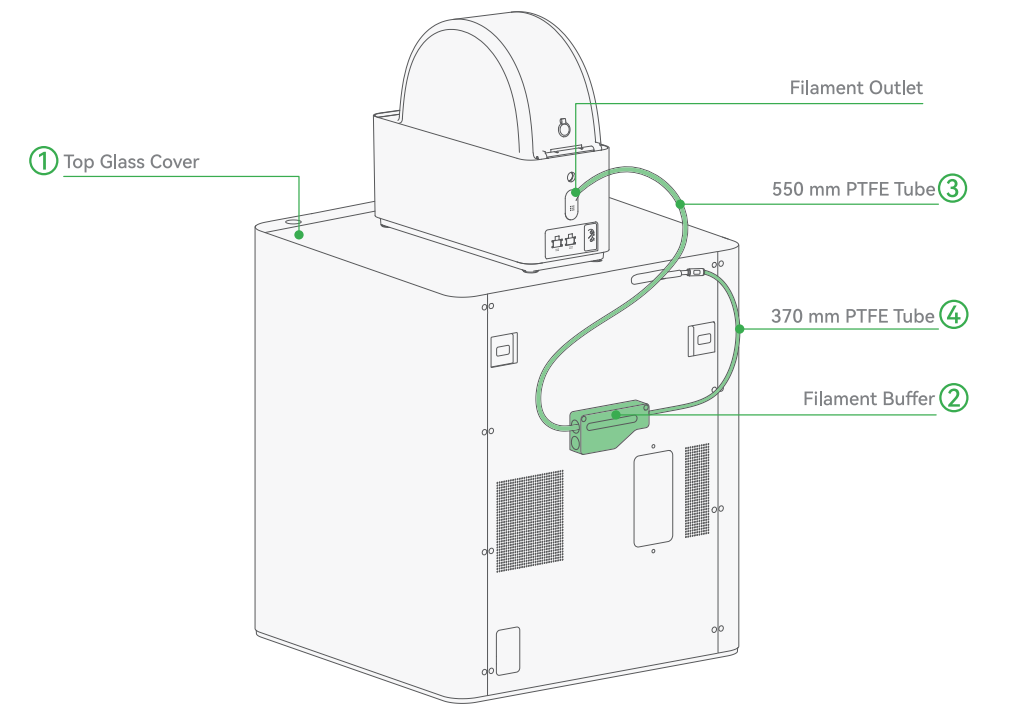
- Connect one end of the 6-pin cable to any 6-pin port on the AMS HT and the other end to the left side of the buffer. Connect the L-shaped end of the 4-pin cable to the printer and the other end to the bottom of the buffer. If using the drying function, connect the power cable to the AMS HT power port.
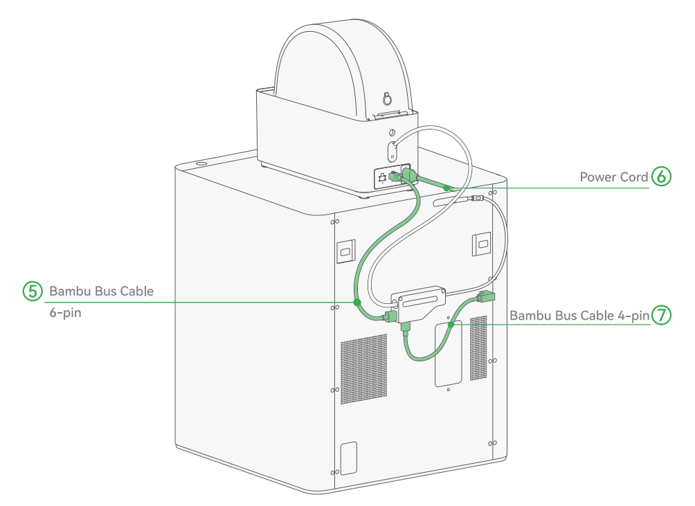
Note: Be sure to use the new 6-pin cable included with AMS 2 Pro and AMS HT. Using the 6-pin cable from the previous generation AMS may cause unstable communication between the AMS and the printer, while the previous generation AMS is compatible with the new 6-pin cable.
¶ Methods for Connecting Multiple AMS Units to X1 or P1 series printers
Bambu Lab printers support connecting more than one AMS unit.
This allows you to store and feed a wider variety of filaments without manual swapping.
There are two main connection methods: using the AMS Hub (recommended) or using a PTFE Tube Adapter.
¶ Method 1 — Using the AMS Hub (Recommended)
The AMS Hub is designed for stable and efficient multi-AMS connections. It ensures smooth filament switching and minimizes feeding errors.
For a complete walkthrough, refer to:
Connecting the AMS Hub and Multiple AMS Units
¶ Method 2 — Using the PTFE Tube Adapter
You can also connect multiple AMS units through a PTFE Tube Adapter: Bambu 4-in-1 PTFE Adapter.
When using this method, two points are critical for reliable operation:
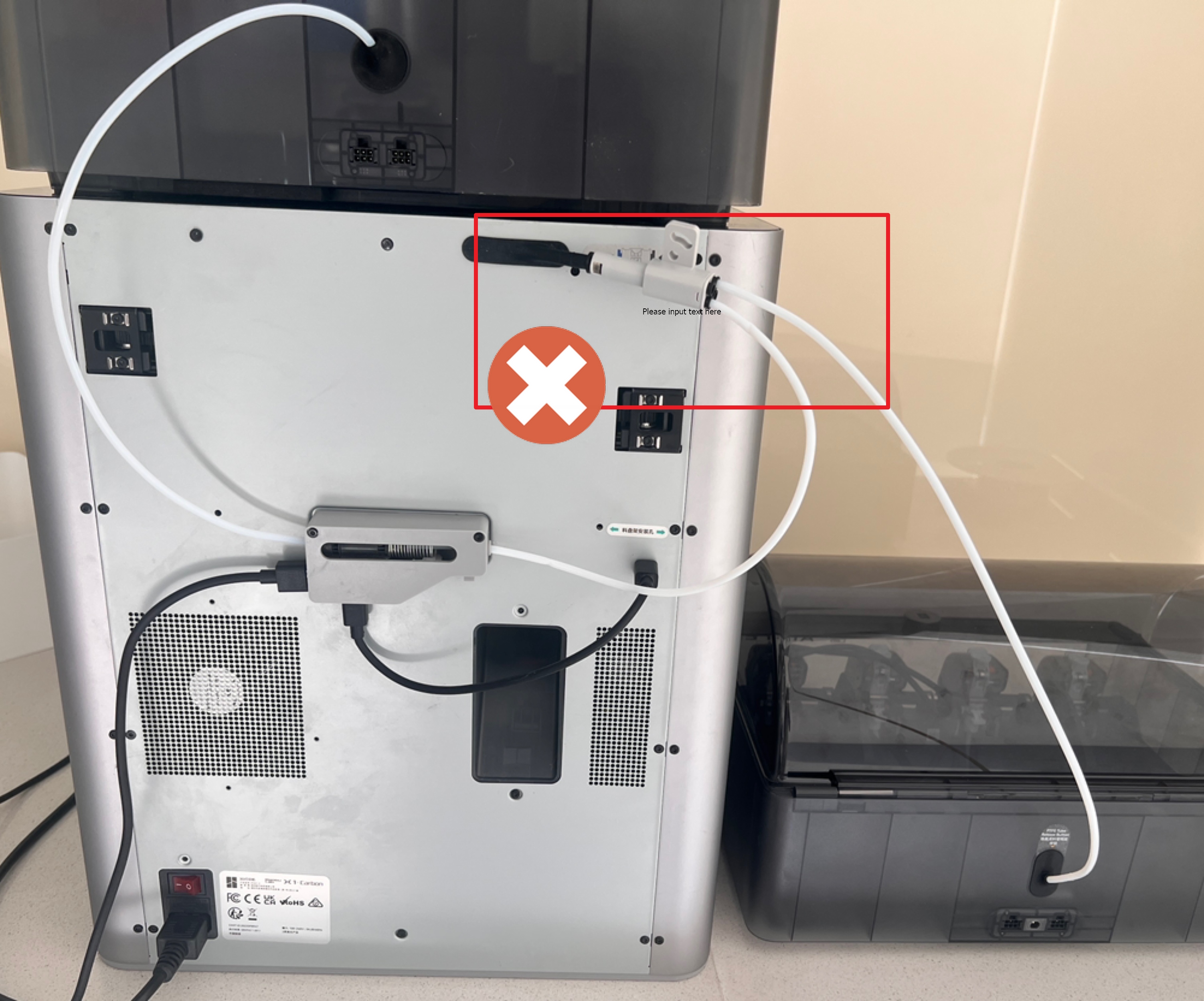
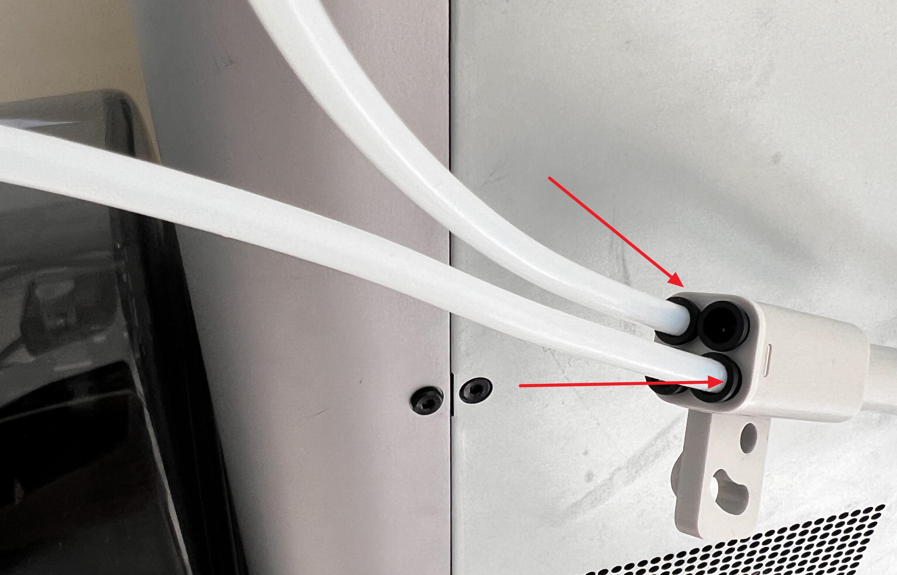
¶ 1. Position the PTFE Tube Adapter on the Left Side of the Filament Buffer
- Why left side?
Connecting on the left side allows all AMS units to feed through the Filament Buffer before reaching the printer.
This helps maintain consistent tension and prevents feeding failures. - What happens if it’s on the right?
The filament bypasses the buffer, increasing the risk of jams or failed loads.
| Correct Installation | Incorrect Installation |
|---|---|
 |
 |
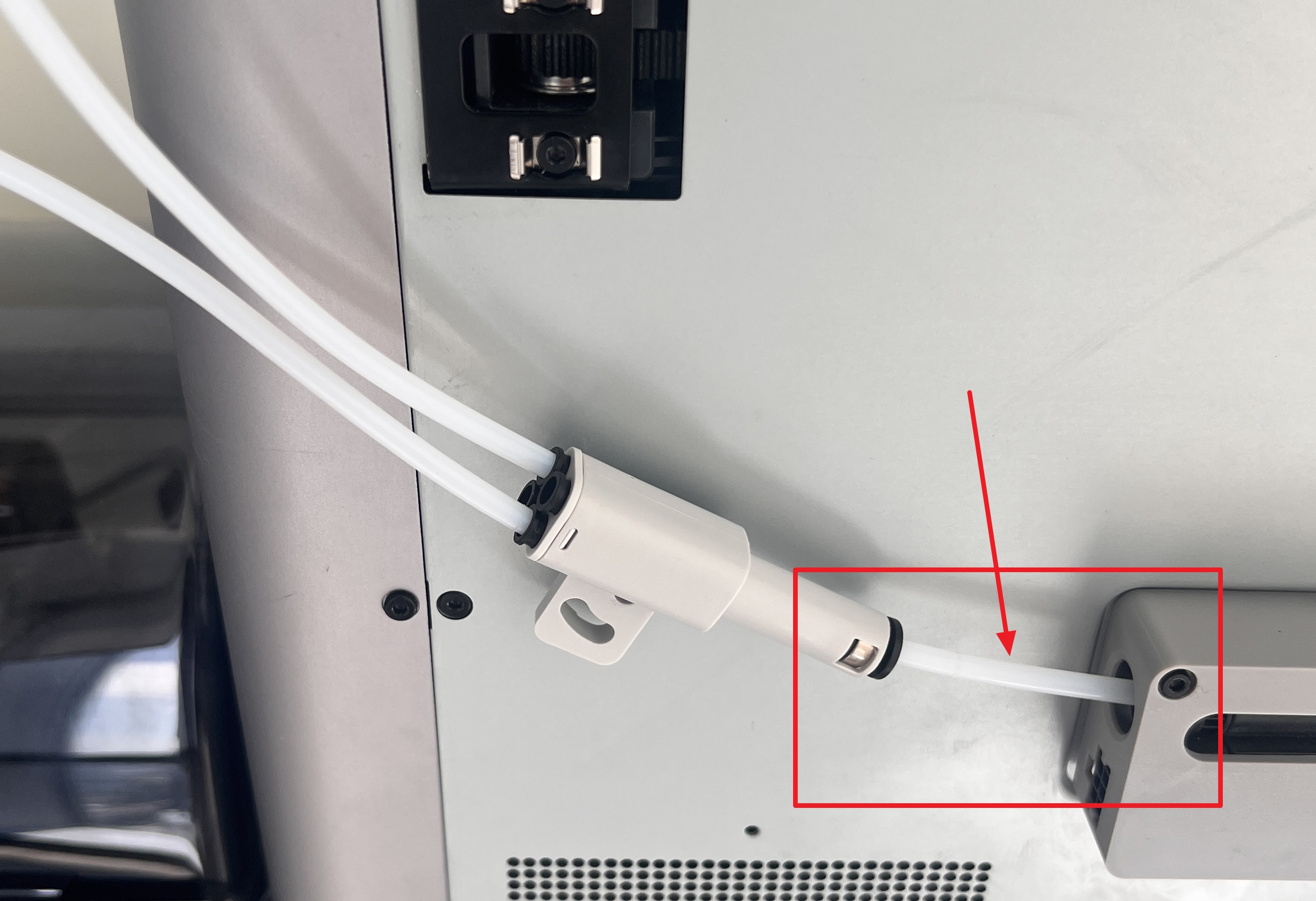
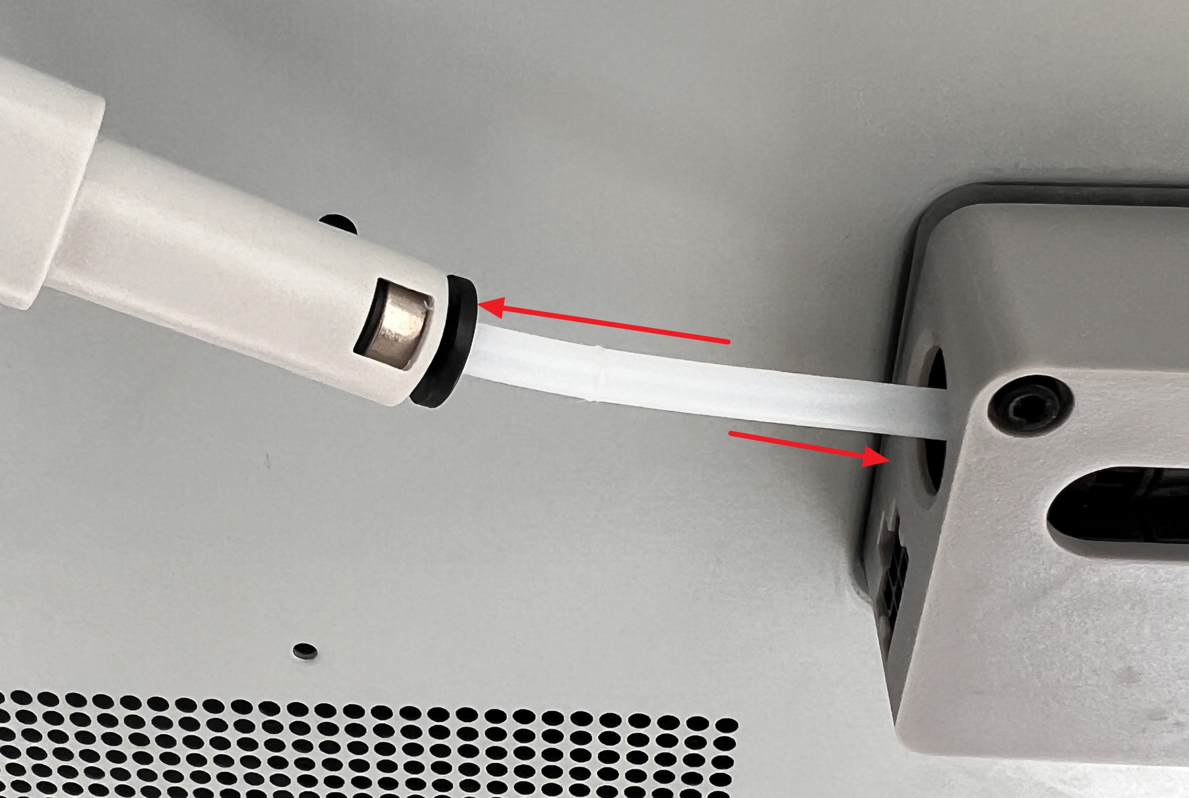
¶ 2. Keep the PTFE Tube Between Adapter and Buffer Short
- Recommended length: Around 10 cm (4 inches).
- Why? A long or sharply bent tube increases friction, which can slow or block filament movement.
- Cut the tube so that it’s just long enough for a smooth, unobstructed feeding.
| Correct Short Tube | Excessive Tube Length |
|---|---|
 |
 |
¶ Installation Guide
¶ Required Tools & Parts
- 1 × Bambu Lab printer
- 2 or more AMS 2 Pro or AMS units
- Several PTFE tubes (cuttable to length)
- PTFE Tube Adapter
¶ Step 1 — Preparation
- Power off all AMS units and stop the printer.
- Confirm the Filament Buffer is securely installed on the printer.
- Gather all PTFE tubes and cut them to the required lengths.
- Pre-cut a 10 cm PTFE tube for connecting the adapter to the buffer.
¶ Step 2 — Connect PTFE Tubes to the AMS Units
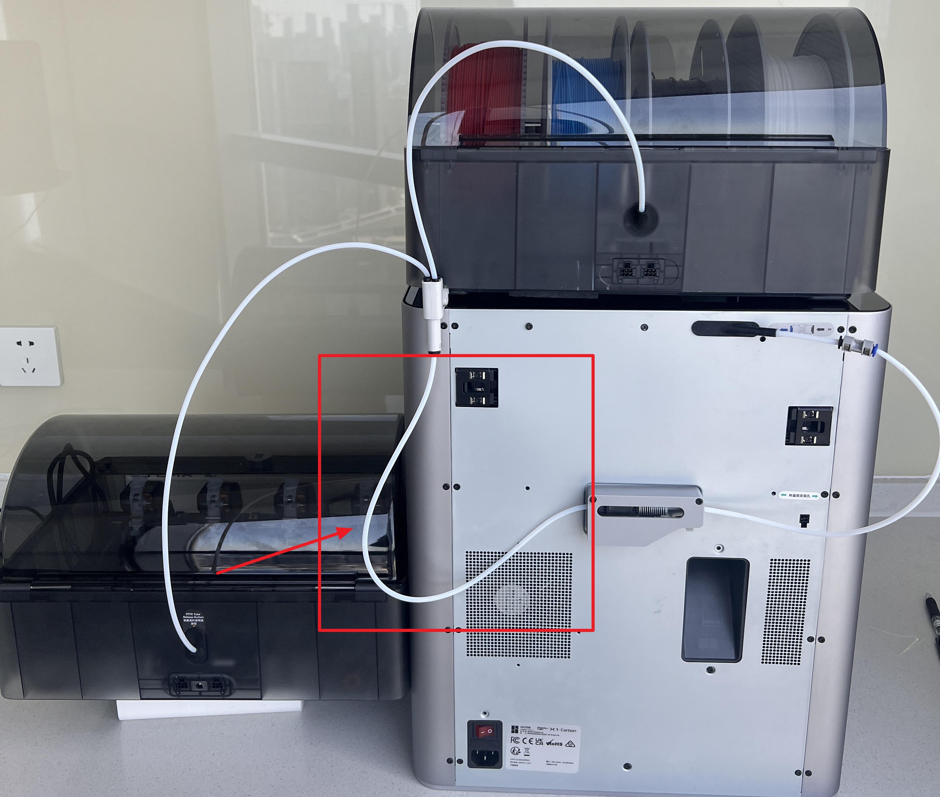
Insert PTFE tubes into the rear push-fit connectors on each AMS unit.
Push until you feel resistance, then check for a secure fit.
¶ Step 3 — Attach the PTFE Tube Adapter
- Position the adapter on the left side of the Filament Buffer.
- Insert the PTFE tube from each AMS unit into the adapter’s input ports.
- Push firmly until the connection is tight and there is no wobble.
¶ Step 4 — Connect Adapter to Filament Buffer
- Take the pre-cut 10 cm PTFE tube.
- Insert one end into the output port of the PTFE Tube Adapter.
- Insert the other end into the left-side input port of the Filament Buffer.
¶ Step 5 — Connect the Printer
Insert the printer’s original PTFE tube into the output port of the Filament Buffer.
¶ Step 6 — Final Checks
- Gently pull on each PTFE connection to confirm it’s locked in place.
- Power on the AMS units and the printer.
- Load filament from each AMS slot to confirm smooth feeding.
- Run a small test print to verify proper switching between filaments.
Tips for Best Performance
- Avoid sharp bends in PTFE tubes — keep curves gentle.
- Store AMS units on the same level as the printer to reduce gravity-related tension.
- Periodically check tube ends for wear and trim if necessary.
¶ End Notes
We hope the detailed guide provided has been helpful and informative.
If this guide does not solve your problem, please submit a technical ticket, we will answer your questions and provide assistance.
If you have any suggestions or feedback on this Wiki, please leave a message in the comment area. Thank you for your support and attention!