¶ AMS Cable Pack (5-in-1)
The pack includes 5 cables:
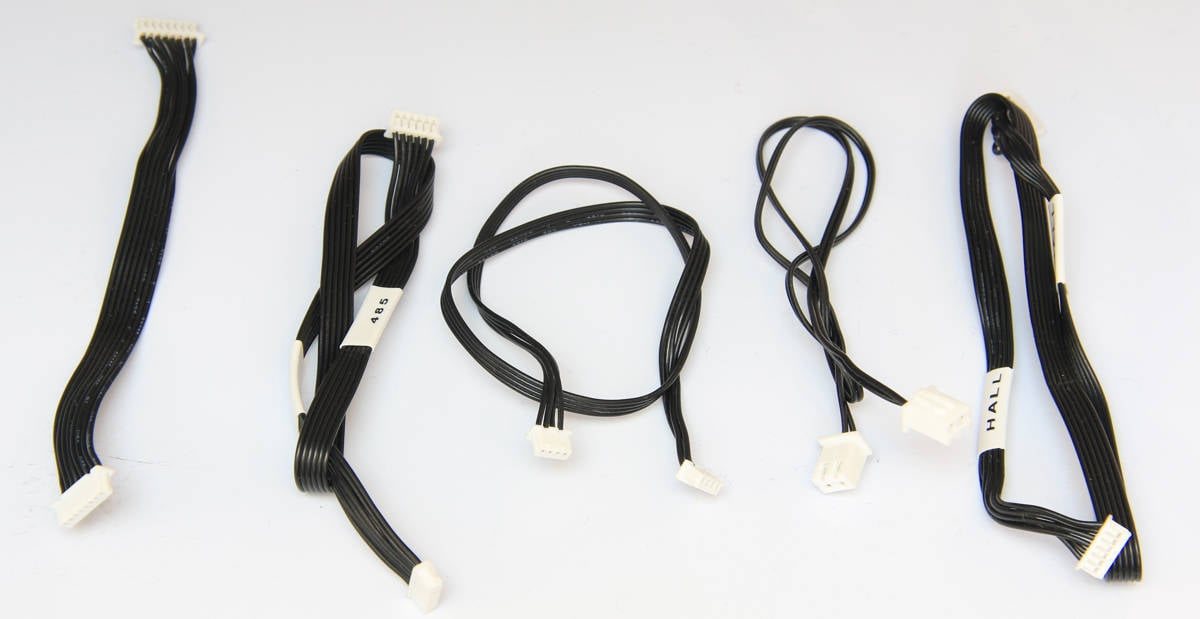
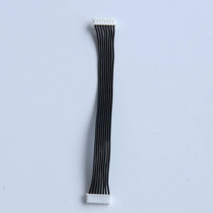
1. RFID board connection cable *1 (Only 1 PCS)
2. Speed measurement board connection cable*1
3. Filament selection board connection cable*1
4. Power supply connection cable*1
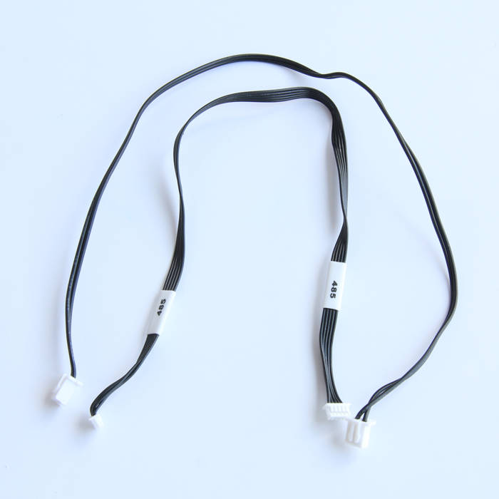
5. 485 bus connection cable*1
¶ When to use
If a cable is damaged during maintenance or becomes burnt during regular use, it should be replaced.
¶ Tools and materials needed
- AMS cable pack
- H2.0 hex key
- Tweezers
Screw list
| Model | Position | Drawing | |
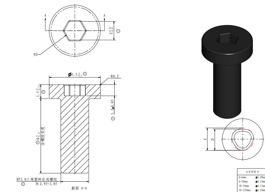
| Screw A | BT3*8 | AMS main frame |
 |
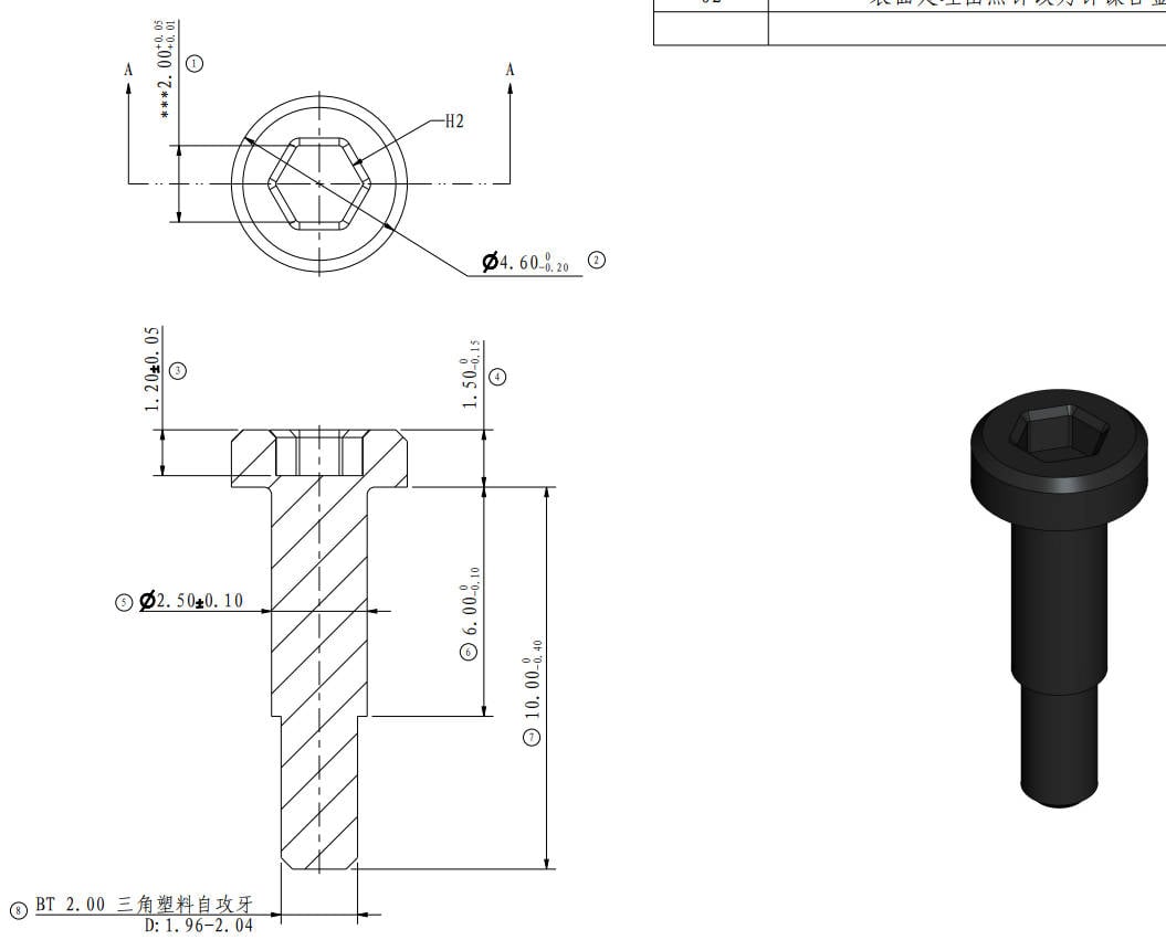
| Screw B | BTG2*8 | AMS internal filaments hub |
 |
¶ Safety Warning
IMPORTANT!
It's crucial to disconnect the AMS from the printer before performing any maintenance work on the AMS and its electronics. Leaving the AMS connected while conducting such tasks can cause a short circuit, leading to additional electronic damage and safety hazards.
If you have any concerns or questions about following this guide, open a new ticket in our Support Page and we will do our best to respond promptly and provide you with the assistance you need.
¶ Remove and install the AMS main frame module
¶ Step 1 (Remove)-Remove the PTFE tube
|
Open the AMS upper cover 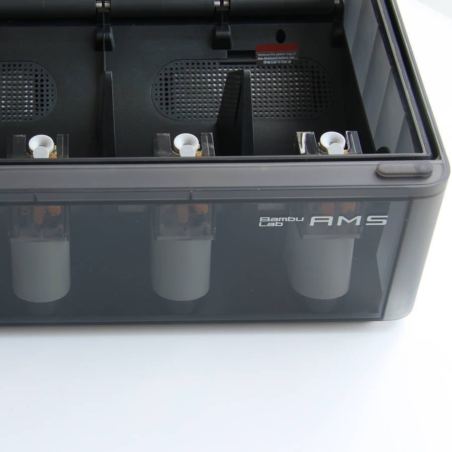 |
Press the button located on the filament hub to release the connector, then gently pull out the PTFE tube 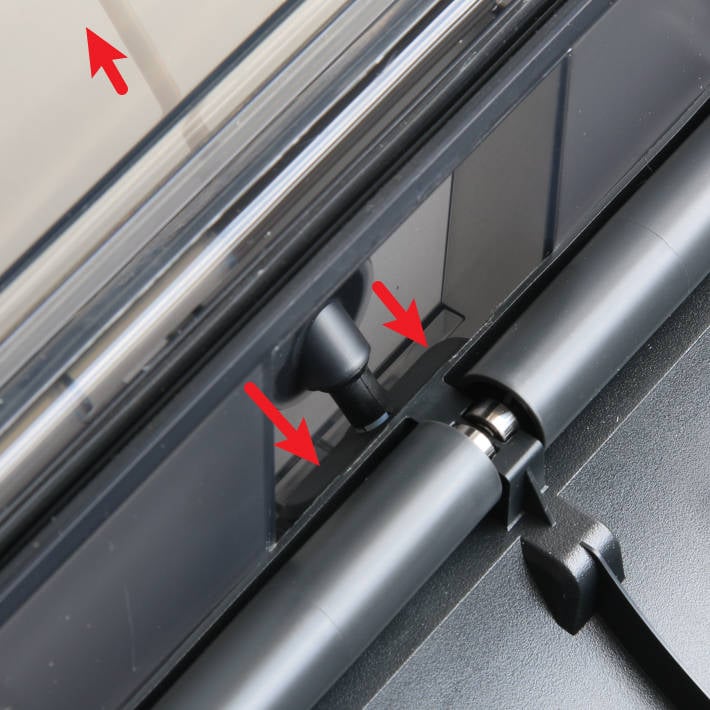
|
¶ Step 2-Release the AMS main frame module
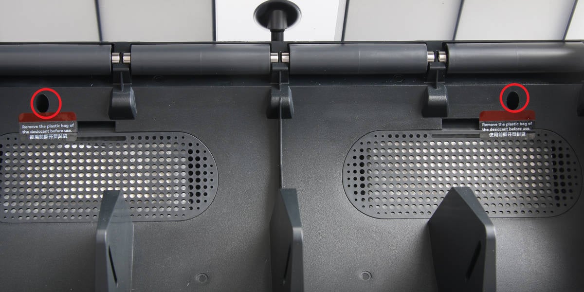
Remove the 2 screws A that secure the AMS main frame.
|
Press the button on the filaments hut to fully lift the rear part of the main frame 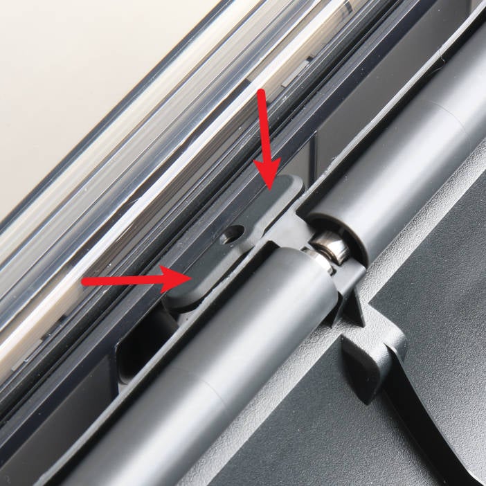 |
Place the main frame components vertically on the AMS bottom shell, paying attention to cable connections 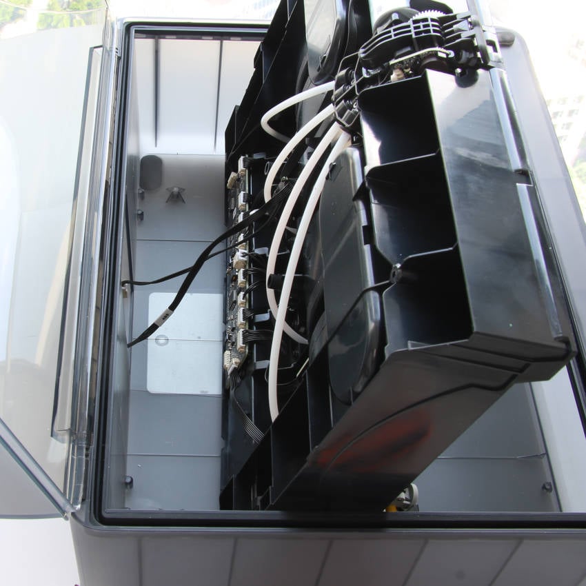
|
¶ Step 3-Remove the AMS main frame module
|
Disconnect the 485 bus cable and power cable from the AMS power board 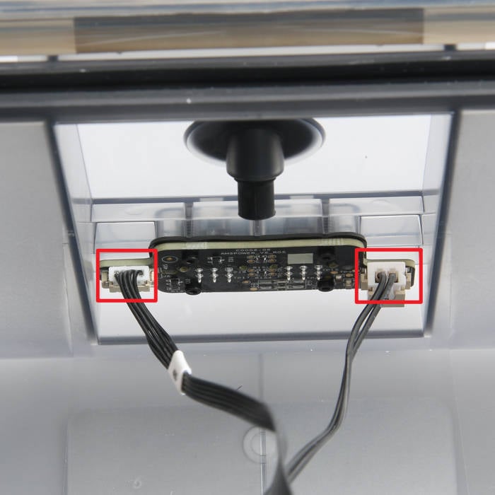 |
Remove the AMS main frame components 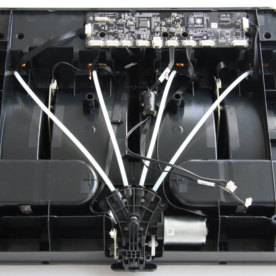 |
¶ Step 4 (Install)-Connect the power cable and 485 bus cable
|
Place the AMS main frame module onto the AMS bottom shell |
Connect the 485 bus cable and power cable to the AMS power board |
¶ Step 5-Install the AMS main frame module
|
Press the button on the filaments hub to install the AMS main frame in place 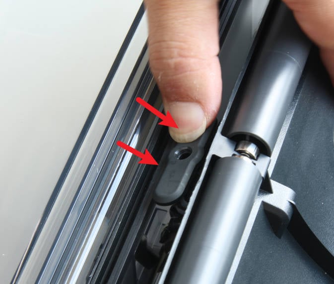 |
Lock in 2 screws A to secure the AMS main frame |
¶ Step 6-Connect the PTFE tube
|
Ensure that the PTFE tube silicone bracket is properly aligned with the pass hole of the filament hub 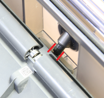 |
Insert the PTFE tube from the rear of the AMS, and after installation, pull the PTFE tube to ensure that it is securely fixed in place 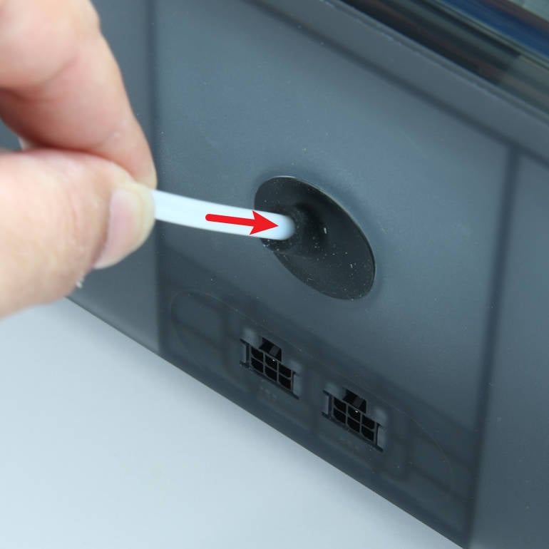 |
¶ Replace RFID cable
¶ Step 1-Remove the RFID cable
|
Disconnect the cable from the AMS main board 1 and the RFID board 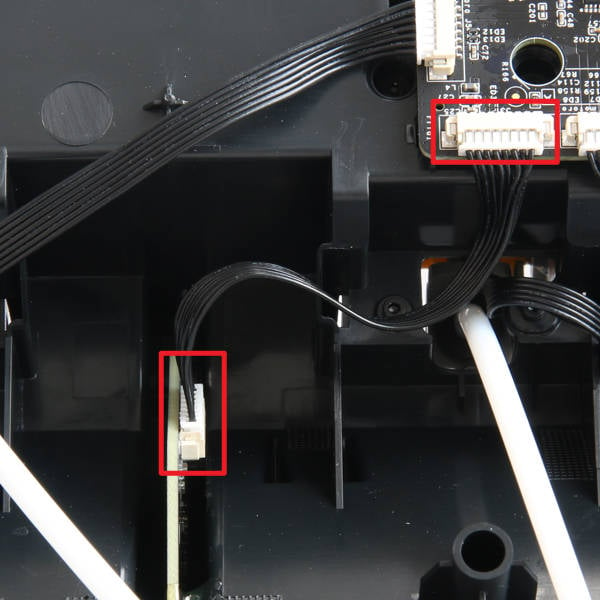 |
(The same step for another RFID cable) Disconnect the connection cable from the AMS main and RFID board 2 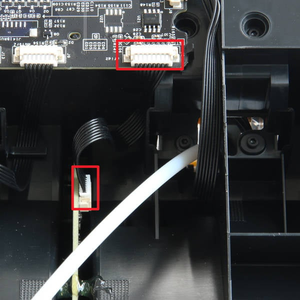 |
¶ Step 2-Connect the RFID cable
|
Connect the RFID cable to the main board according to the direction shown in the picture 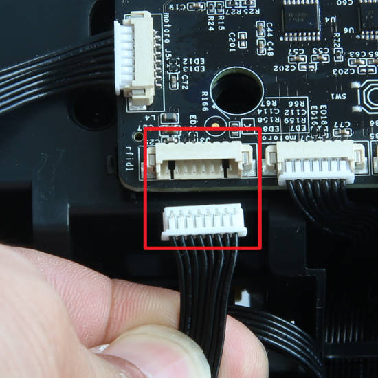 |
Connect the RFID cable to the RFID board according to the direction shown in the picture 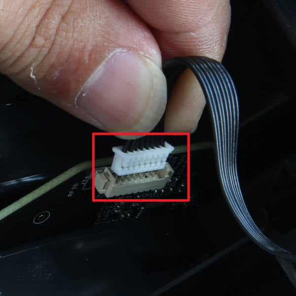 |
¶ Replace the power cable and 485 bus cable
¶ Step 1-Disconnect the cables
|
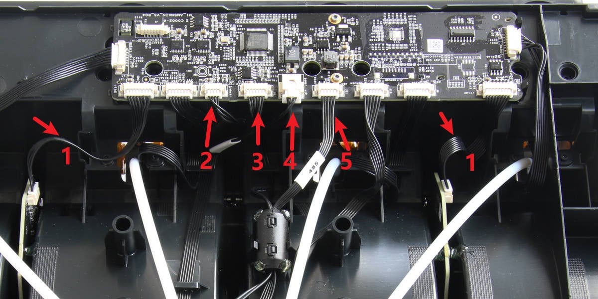
Find the connectors for the two cables on the main board and disconnect them 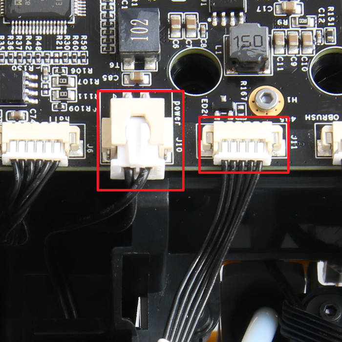 |
Insert the hex key through the bracket of the magnetic ring and carefully pry up the magnetic ring 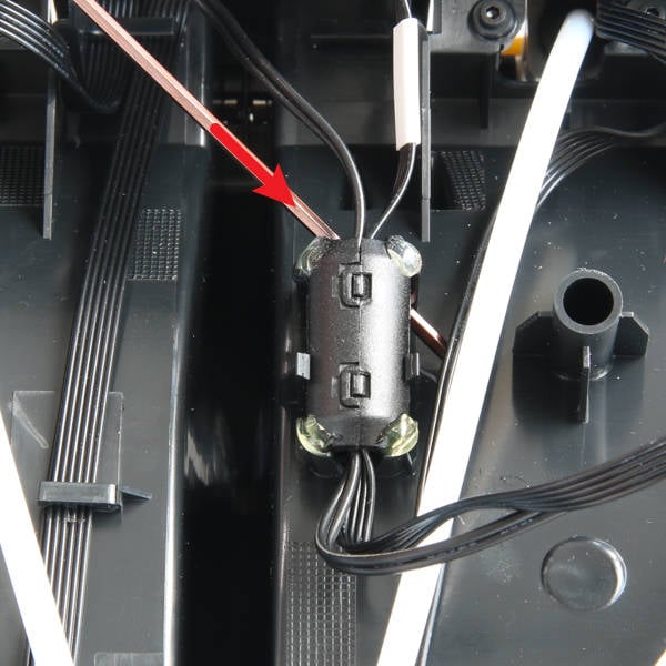 |
¶ Step 2-Remove the cables
|
Unlock the two clips 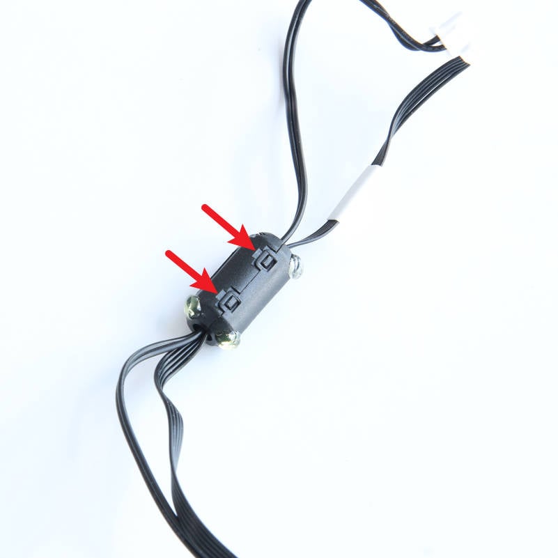 |
Open the magnetic ring and remove the cables 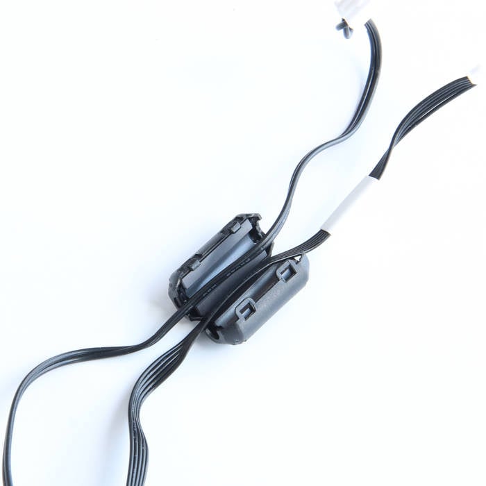 |
¶ Step 3-Connect the cables
Connect the power cable and 485 bus cable to the corresponding connectors of the AMS main board
¶ Step 4-Install the magnetic ring
|
Insert the power cable and 485 bus cable into the magnetic ring, then secure them to the bracket. 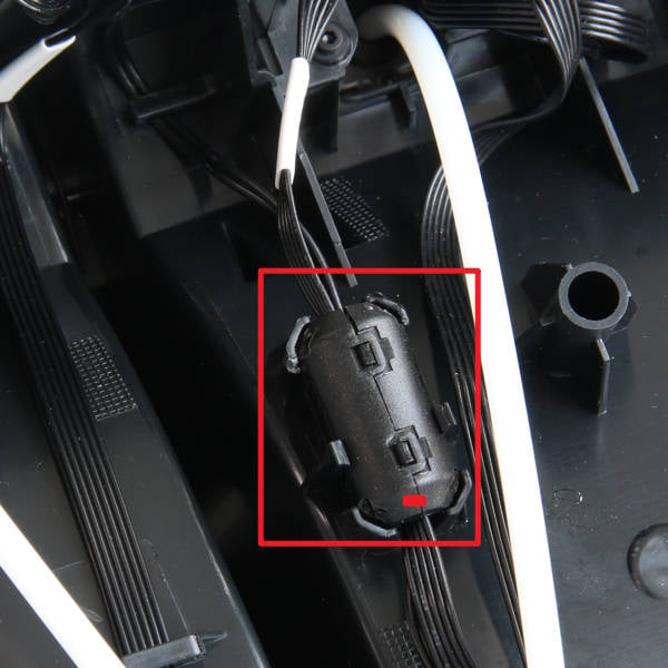 |
The magnetic ring can be reinforced with glue 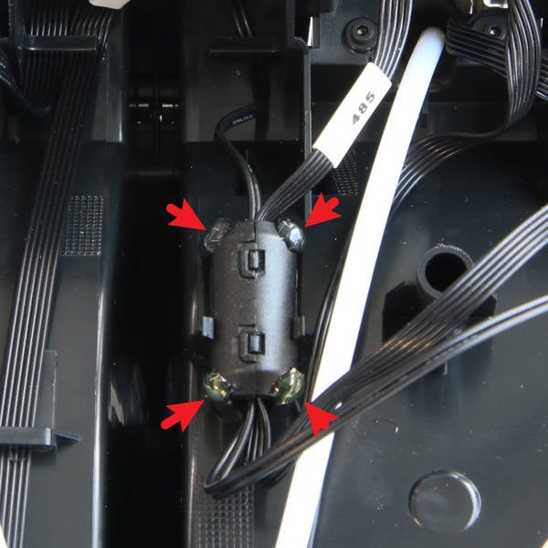 |
¶ Replace the connection cable of the filament selection board and the speed measurement board
¶ Step 1-Disconnect from the main board
|
Press the tube joints to disconnect the 4 PTFE tubes from the filaments hub 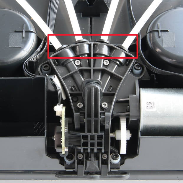 |
Disconnect the speed measurement board cable and the filament selection board cable from the main board, and release them from the 2 clips 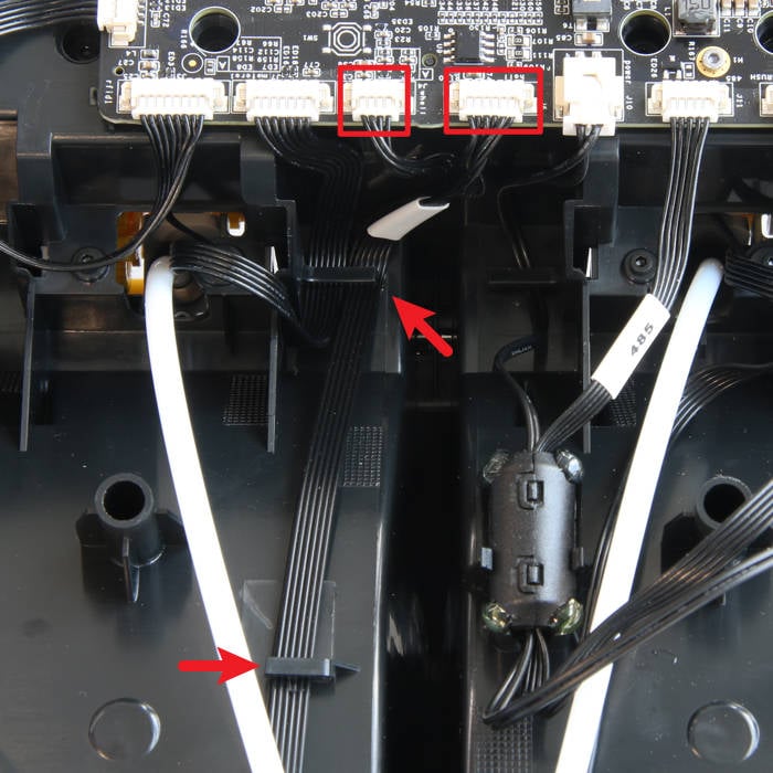 |
¶ Step 2-Remove the filaments hub
|
Remove 4 screws B with H2.0 hex key 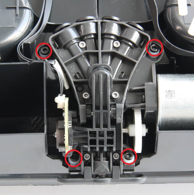 |
Release the filaments hub from the main frame 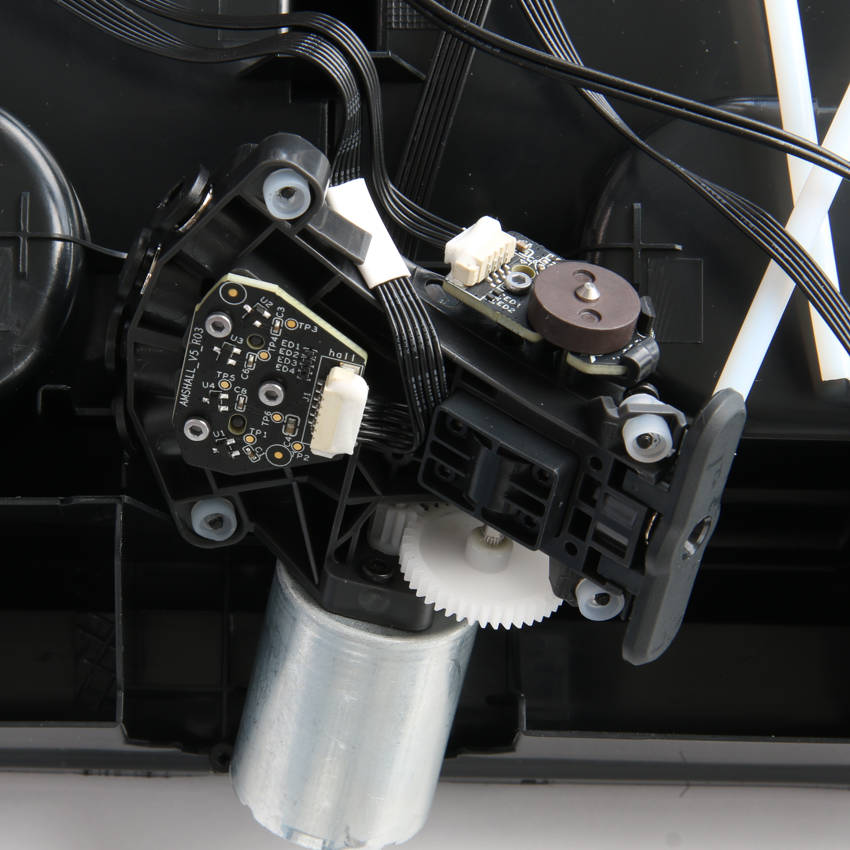 |
¶ Step 3-Remove the cables
Use tweezers to remove excess silicone glue from the connectors, then disconnect the 2 cables and remove them.
¶ Step 4-Connect cables to the filaments hub
|
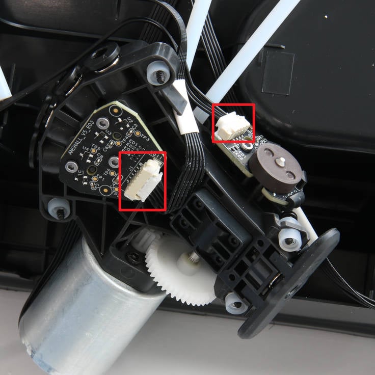
Connect the 2 cables to the filaments hub |
Apply silicone glue to the two connectors to reinforce them 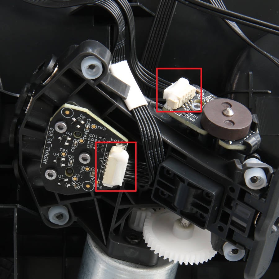 |
¶ Step 5-Install the filaments hub
|
Install the filaments hub onto the main frame, ensuring that each rubber sleeve is installed in place 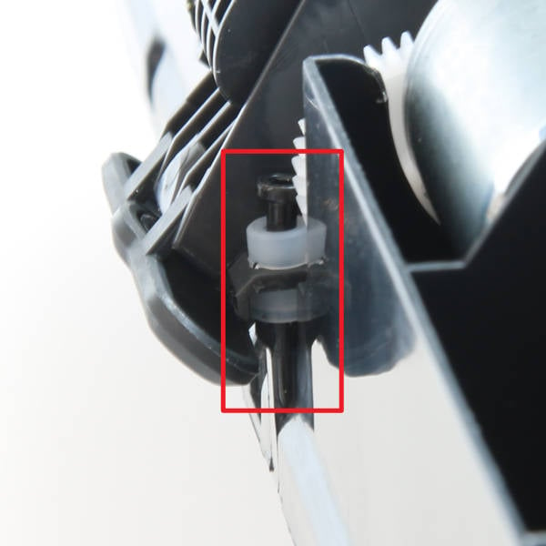 |
Lock in 4 screws B with H2.0 hex key to fix the filaments hub |
¶ Step 6-Connect the cables and the PTFE tubes
|
Connect the 2 cables to the main board and organize them properly into the clips. |
Connect 4 PTFE tubes |
¶ How to verify completion/success
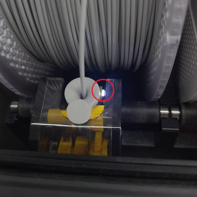
1. Connect the AMS to the printer and power on the printer to supply power to the AMS. The indicator light on the first stage feeder should illuminate, indicating normal power supply.
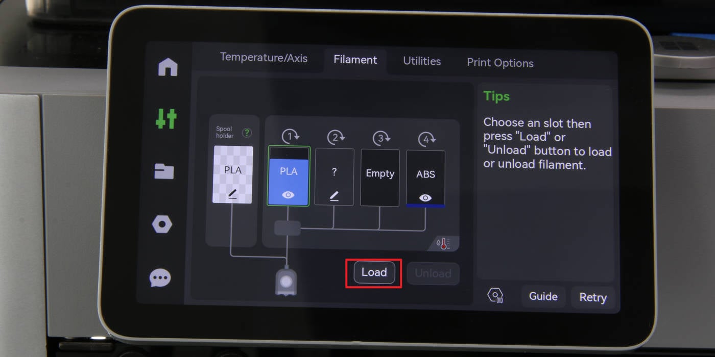
2. Load a filament with an RFID chip and ensure that AMS recognizes the filament correctly. Click "Load" to feed the filament, and confirm that AMS successfully delivers the filament to the extruder.
Otherwise, retrace your steps, check the connections, and try again. If problems persist, contact the technical support team for further assistance.
¶ Calibration step after the procedure
No further calibration is necessary.
¶ End Notes
We hope the detailed guide provided has been helpful and informative.
To ensure a safe and effective execution, if you have any concerns or questions about the process described in this article, we recommend reaching out to technical support team before initiating the operation. We will do our best to respond promptly and provide the assistance you need. Click here to open a new ticket in our Support Page.