¶ AMS lite Installation Tutorial
This article provides the guidelines and precautions for the disassembly and assembly of the AMS Lite. The disassembly and assembly of replaceable accessories involved in this disassembly process can also be handled with reference to this article.
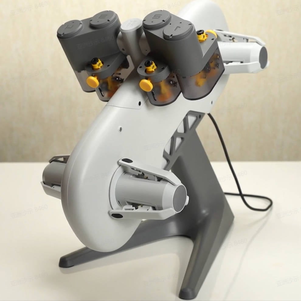
¶ Parts List
The following are the after-sales individual items that will be involved in this guide.
| No. | Name | Image | No. | Name | Image |
| 1 | AMS Rotary Spool Holder (Green) |
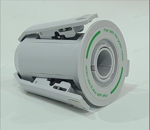 |
2 | AMS Rotary Spool Holder (Yellow) |
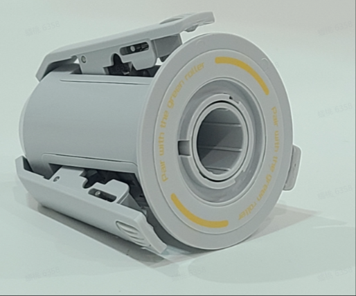 |
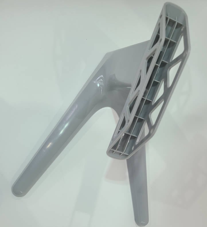
| 3 | AMS lite Stand |
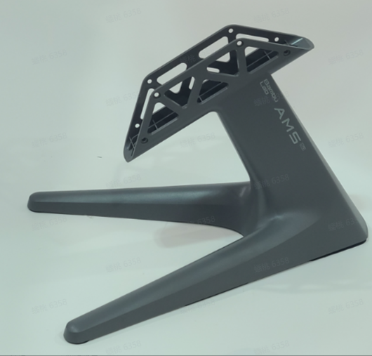 |
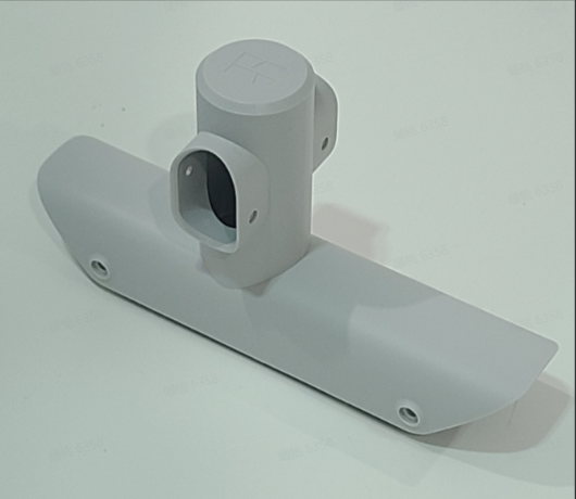
4 | AMS Filament Holder Rod |
 |
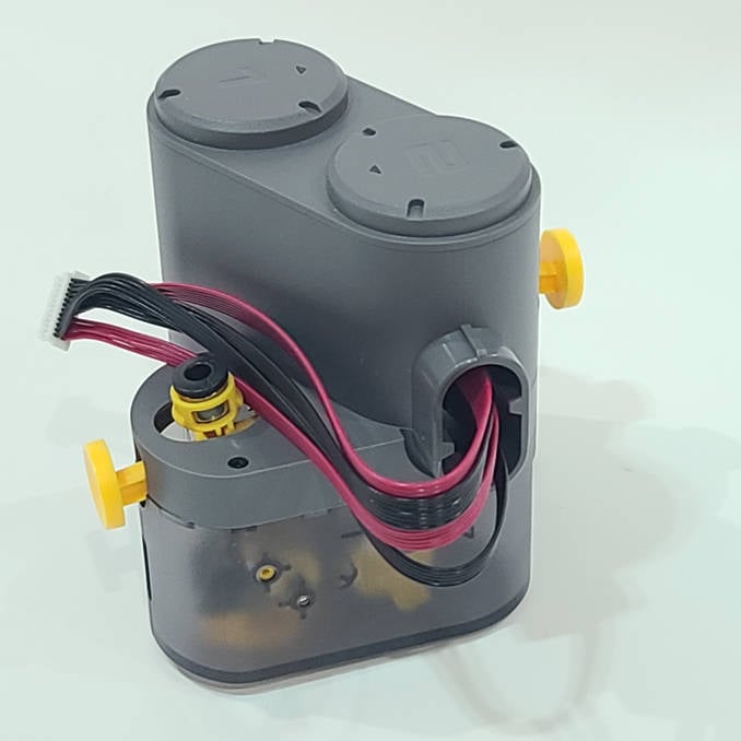
| 5 | AMS Left Feeder Unit (1 and 2) |
 |
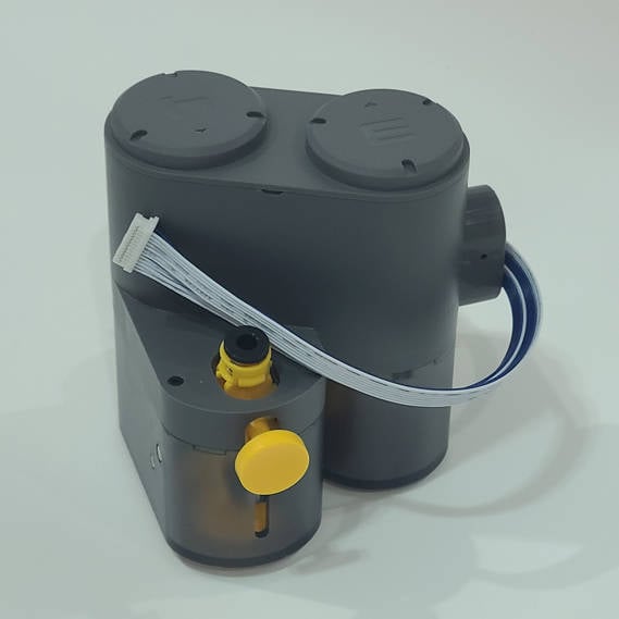
6 | AMS Right Feeder Unit (3 and 4) |
 |
¶ Assembly List
The assembly unit is not provided and doesn't need further disassembly.
| No. | Name | Image |
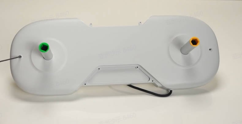
| 1 | AMS lite Main Body |
 |
¶ Screw List
| Model | Position | Drawing | Model | Position | Drawing | ||
| Screw A |
BT3*6 B0021 |
AMS Filament Holder Rod: 4PCS AMS Stand: 4PCS |
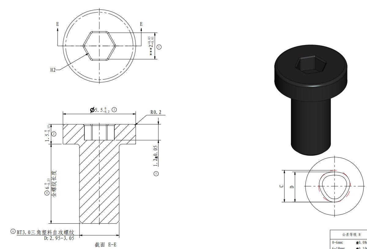 |
Screw B |
BT2*5 B0017 |
AMS Left Feeder Unit :4PCS
|
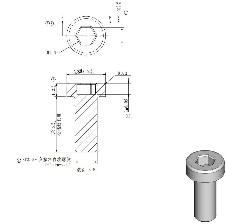 |
¶ Tool List
H1.5 / H2.0 hex key
¶ Safety Warning
IMPORTANT!
It's crucial to disconnet the AMS Lite from the printer before performing any maintenance work on the AMS and its electronics, because leaving the AMS connected while conducting such tasks can cause a short circuit, which can lead to additional electronic damage and safety hazards.
If you have any concerns or questions about following this guide, open a new ticket in our Support Page and we will do our best to respond promptly and provide you with the assistance you need.
¶ Video Guide
¶ Assemble the AMS lite
¶ Step 1 - Install the AMS Stand
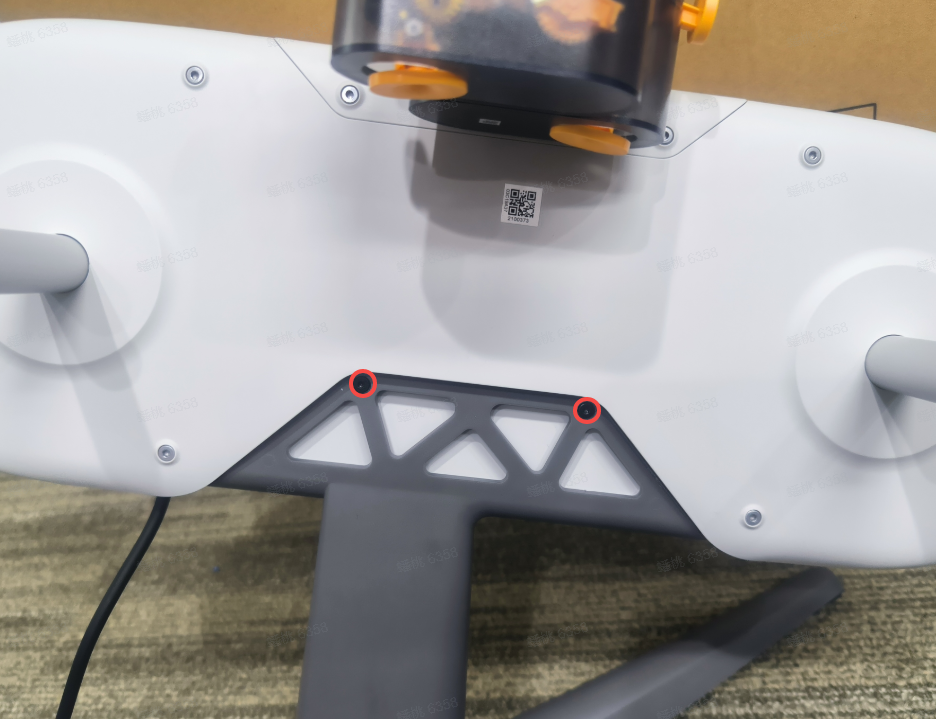
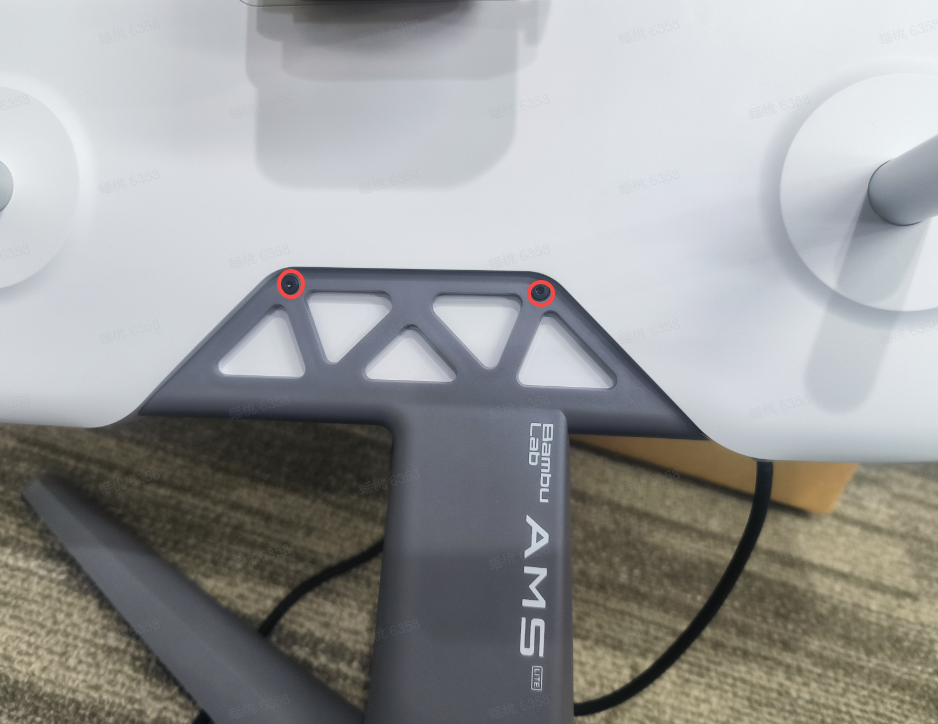
Place the AMS housing assembly on the AMS Stand with the power cord facing up, gently press the AMS Lite main body to the fully expose the screw holes; Lock the 4 screws A on the left and right sides in turn to secure the AMS Stand.
 |
 |
¶ Step 2 - Install the AMS Left/Right Feeder Units
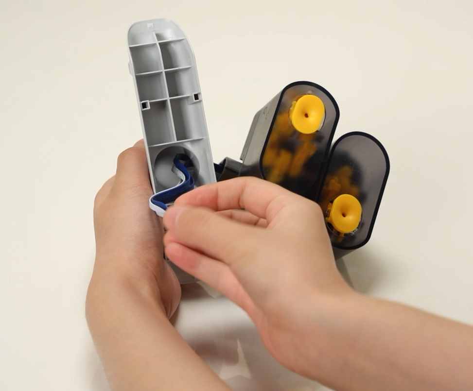
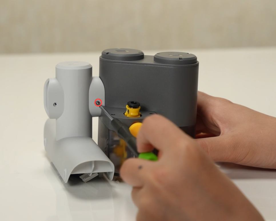
Thread the blue and white cable through the AMS Filament Holder Rod and lock in 2 screws B to fix the AMS Feeder Unit (3/4).
 |
 |
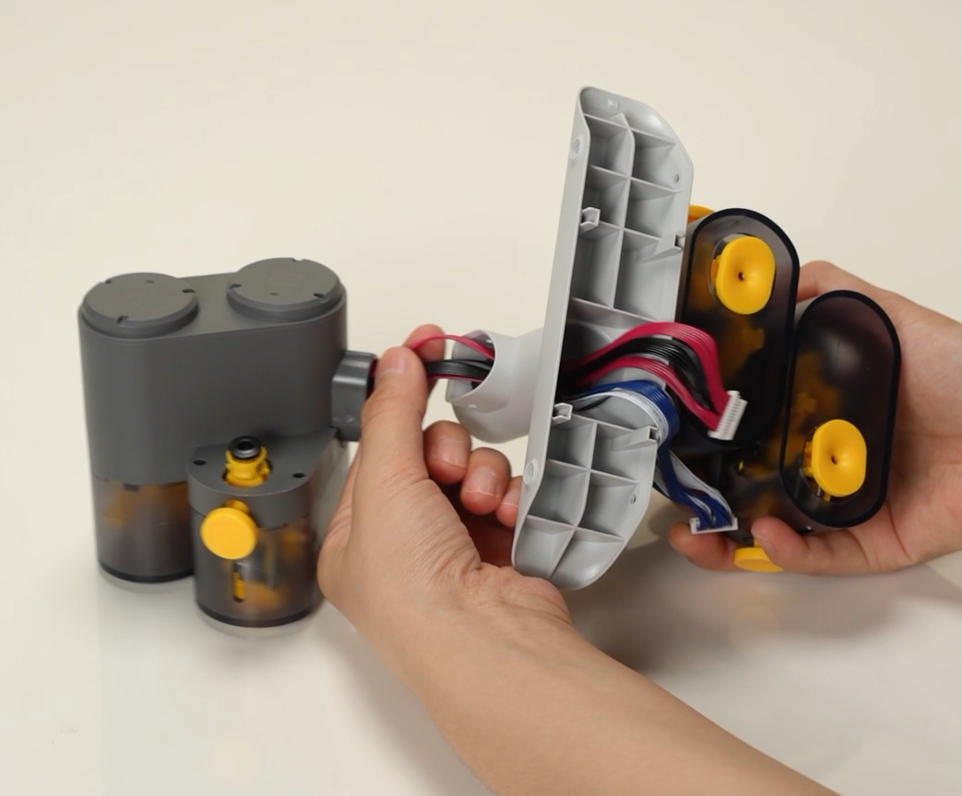
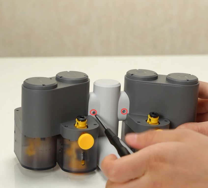
Thread the black and red cable through the AMS Filament Holder Rod and lock in 2 screws B to fix the AMS Feeder Unit (1/2).
 |
 |
¶ Step 3 -Install the AMS Feeder Assembly
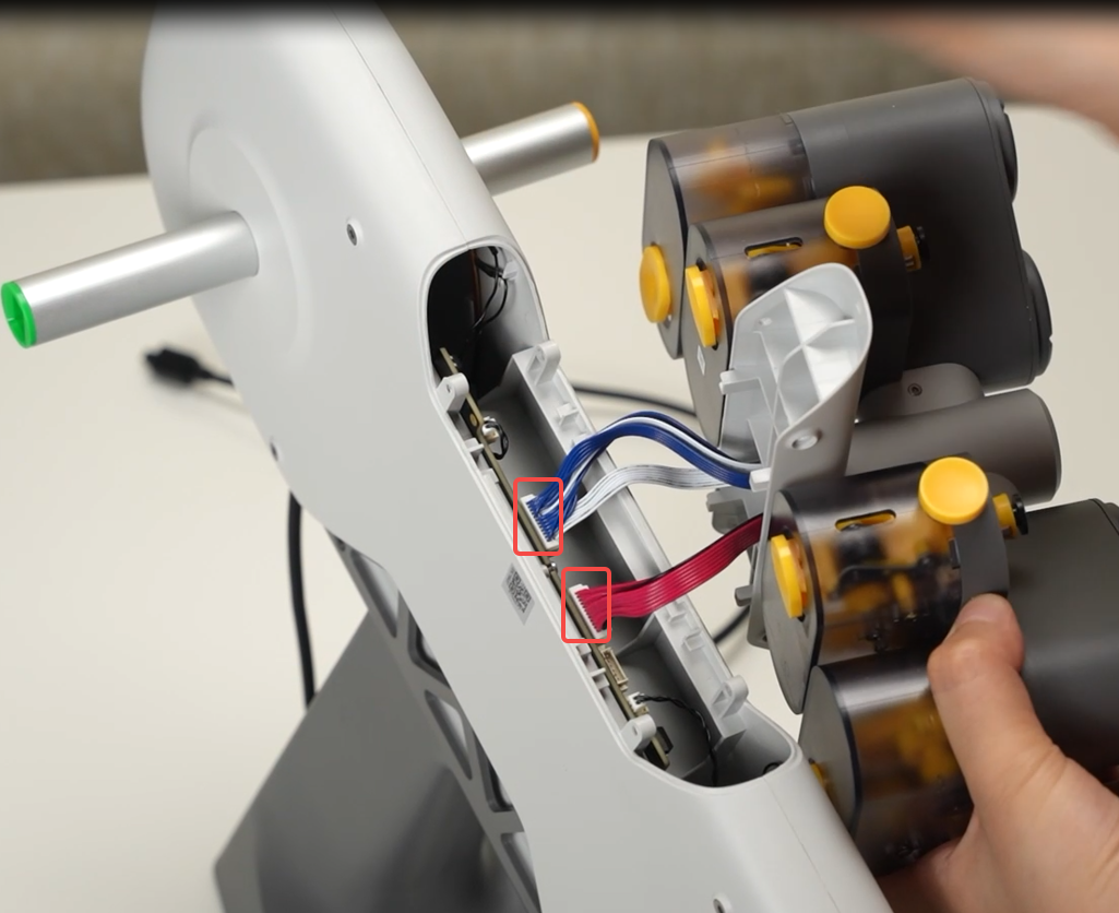
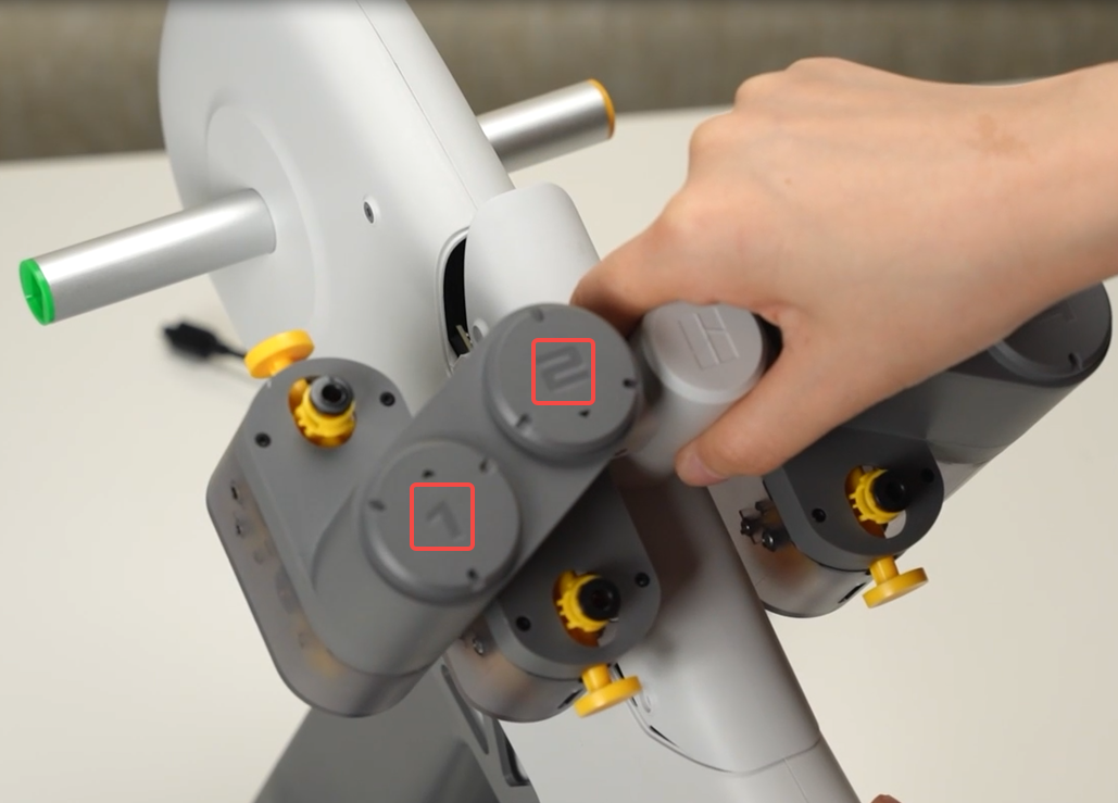
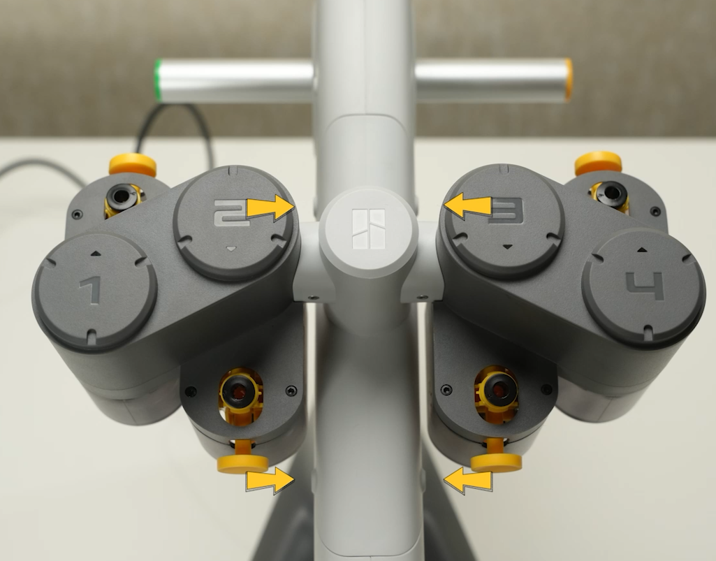
Connect the 2 connecting cables per color; Mount the AMS Feeder Assembly to the AMS Lite main body and lock it with 4 screws A.
 |
 |
 |
¶ Step 4 - Install the AMS Rotary Spool Holders
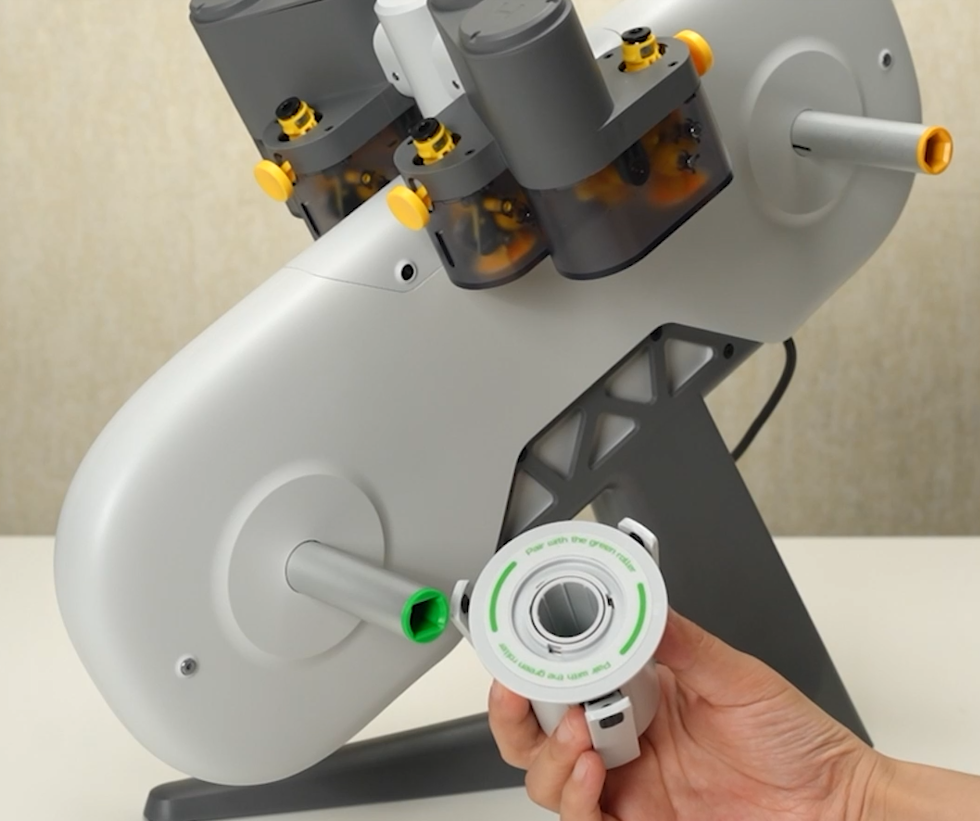
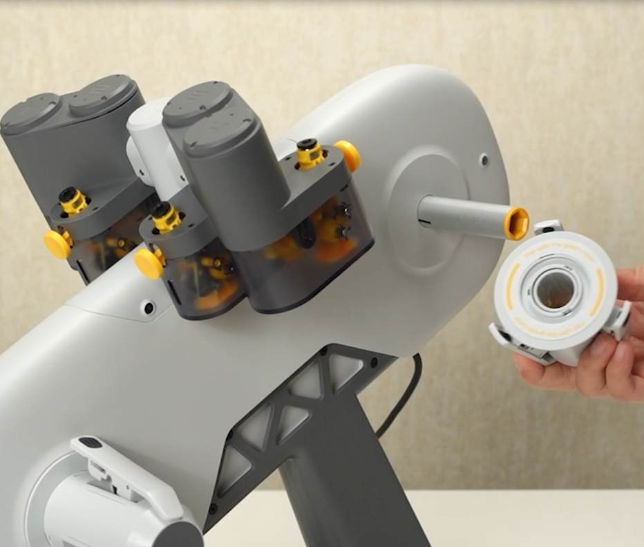
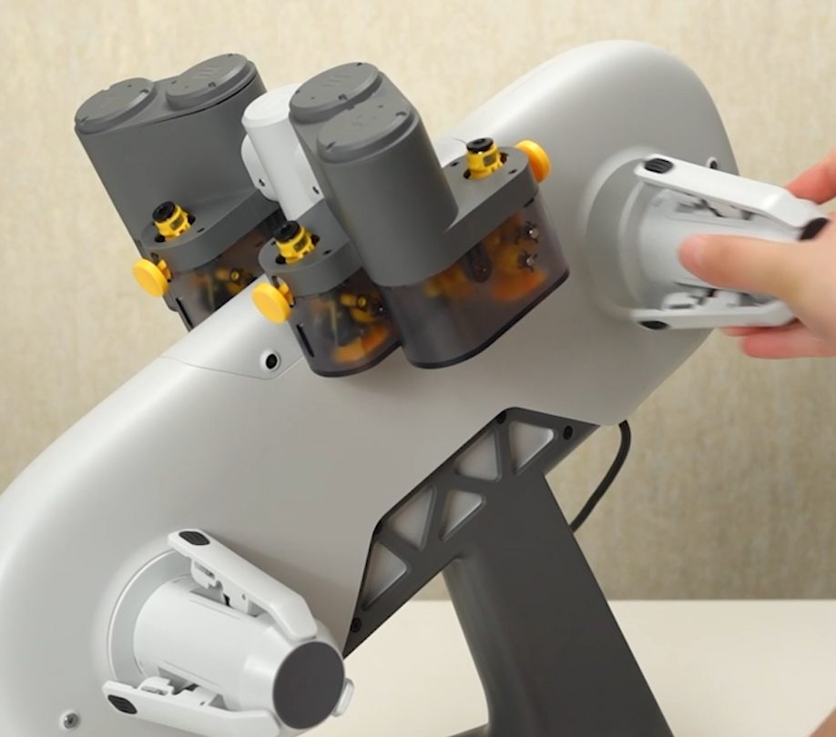
Pair and install the four AMS Rotary Spool Holders per color in turn. Pay attention to the mounting direction before installation.
 |
 |
 |
¶ Disassemble the AMS lite
¶ Step 1 - Remove the four AMS Rotary Spool Holders
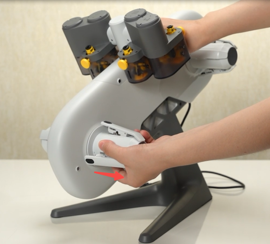
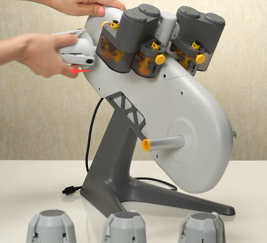
Disconnect the AMS Lite from the printer first; Hold the AMS Lite by hand, and pull off the 4 AMS Rotary Spool Holders in turn.
 |
 |
¶ Step 2 - Remove the AMS Feeder Assembly
Remove the 4 screws A marked in the left image below, disconnect the black and red cable and the blue and white cable, then remove the whole AMS Feeder Assembly from the AMS Lite.
 |
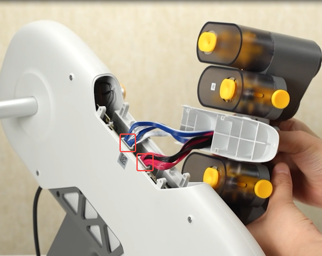 |
¶ Step 3 - Remove the AMS Feeder Units
Remove the AMS Feeder Units (1/2) by unscrewing the 2 screws B marked in the left image below.
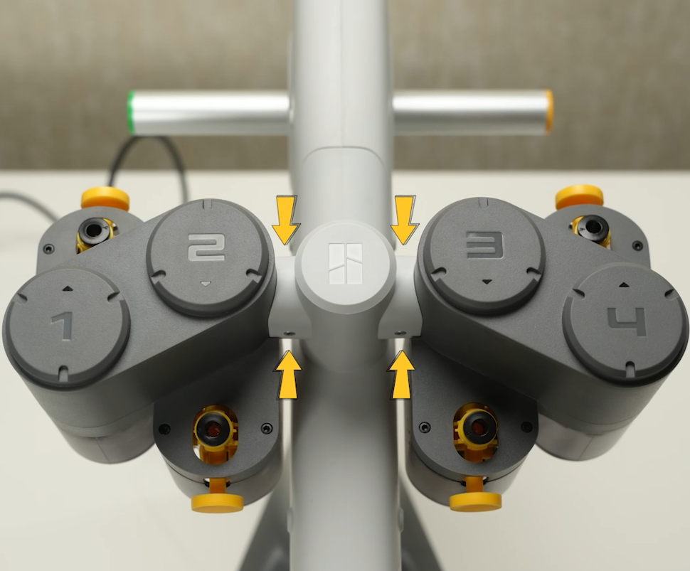 |
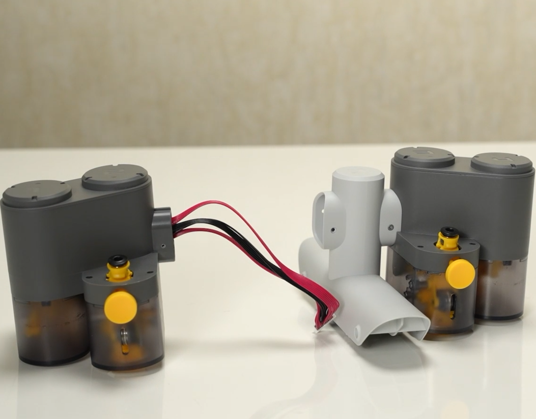 |
Remove the AMS Feeder Units (3/4) by unscrewing the 2 screws B marked in the left image below.
 |
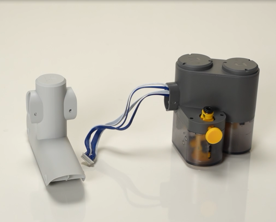 |
¶ Step 4 - Remove the AMS Stand
Remove the AMS Stand by unscrewing the 4 screws A (2 on each left and right side).
|

|
 |
 |
¶ Verify the functionality
1. Connect the AMS Lite to the printer, turn on the printer power, and check if the indicator lights on the AMS Feeder are lit normally;
2. Insert filament to test the load/unload function of the AMS Lite;
If the test fails, please check all connections again and retry. If it still does not work, please contact the Bambu Lab service team.
¶ Calibration step after the operation
Not required
¶ End Notes
We hope that the detailed guide we shared with you was helpful and informative.
We want to ensure that you can perform it safely and effectively. If you have any concerns or questions regarding the process described in this article, we encourage you to reach out to our friendly customer service team before starting the operation. Our team is always ready to help you and answer any questions you may have.
Click here to open a new ticket in our Support Page.
We will do our best to respond promptly and provide you with the assistance you need.