¶ Phenomenon
When the AMS cannot be detected by the printer, users may observe blinking red (or white in some older AMS version) LEDs in all AMS slots, and the AMS tab will not appear on the printer screen. This issue is usually caused by a communication failure between the AMS and the printer.
This document provides a method for using a multimeter to check the resistance across specific pins in the AMS connector cables. By comparing the measured values with known normal ranges, users can identify whether the AMS mainboard is likely malfunctioning.
¶ Tools needed
- Multimeter
¶ Applicable to AMS, AMS 2 Pro, and AMS HT
The test method and resistance range are the same for those three devices. The following explanation uses the AMS 2 Pro as an example:
¶ Step One: Preparation
Disconnect 6-pin cable between AMS 2 Pro and the printer. Power off the device and let it sit for at least 1 minute to ensure the circuit is fully discharged, avoiding measurement errors.
¶ Step Two: Resistance Measurement Procedure
Use a multimeter to measure the resistance between the following pin combinations on the 6-pin interface. A diagram showing the 6-pin cable interface is provided below:

| Pin Combination | Normal Range (General) | Measured Reference Value |
|---|---|---|
| GND-sigA | 4~5 kΩ | AMS 2 Pro:4.41 kΩ AMS HT:4.46 kΩ AMS:4.41 kΩ |
| GND-sigB | 5~6 kΩ | AMS 2 Pro:5.13 kΩ AMS HT:5.33 kΩ AMS:5.39 kΩ |
| sigA-sigB | 8~10 kΩ | AMS 2 Pro:9.03 kΩ AMS HT:9.15 kΩ AMS:9.15 kΩ |
⚠️ Note: Actual measured values may slightly vary due to ambient temperature, circuit aging, or instrument error, but should still fall within the normal range.
¶ Step Three: Fault Diagnosis:
If the measured resistance values fall outside the normal ranges listed above, the issue is likely a communication failure caused by a malfunctioning AMS mainboard.
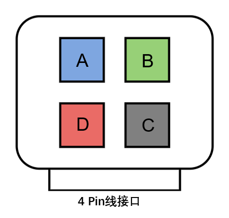
¶ Applicable to AMS lite
¶ Step One: Preparation
Disconnect 4-pin cable between AMS lite and the printer. Power off the device and let it sit for at least 1 minute to ensure the circuit is fully discharged, avoiding measurement errors.
¶ Step Two: Resistance Measurement Procedure
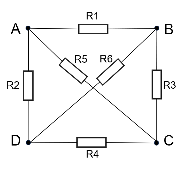
Use a multimeter to measure the resistance between the following pin combinations on the 4-pin interface. A diagram showing the 4-pin cable interface and resistance measurement points is provided below:
 |
 |
|---|
The normal resistance values between each of the two points shown in the diagram above are listed in the table below:
| No. | R1 | R2 | R3 | R4 | R5 | R6 |
|---|---|---|---|---|---|---|
| Resistance | 320 Ω | 130 kΩ | 2.7 kΩ | 130 kΩ | 2.7 kΩ | 130 kΩ |
¶ Step Three: Fault Diagnosis
If the measured resistance values fall outside the normal ranges listed above, the issue is likely a communication failure caused by a malfunctioning AMS mainboard.