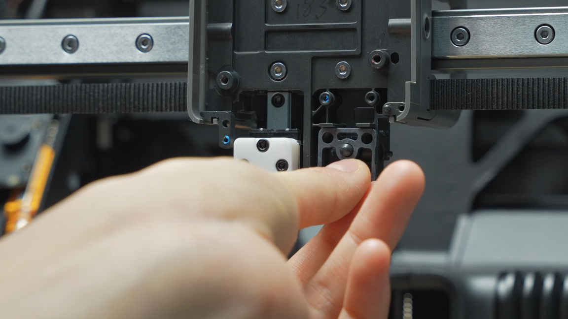
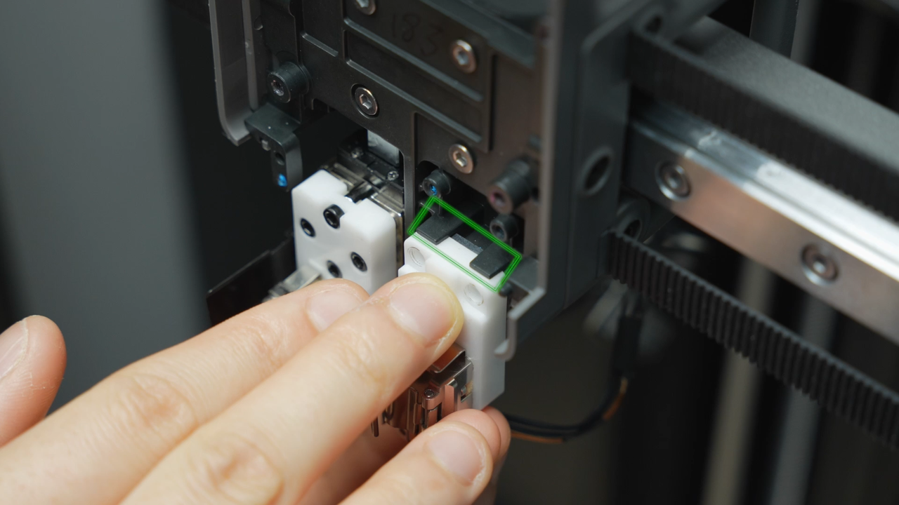
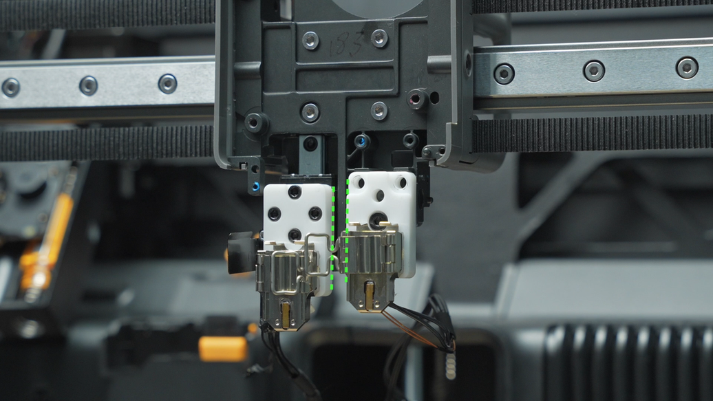
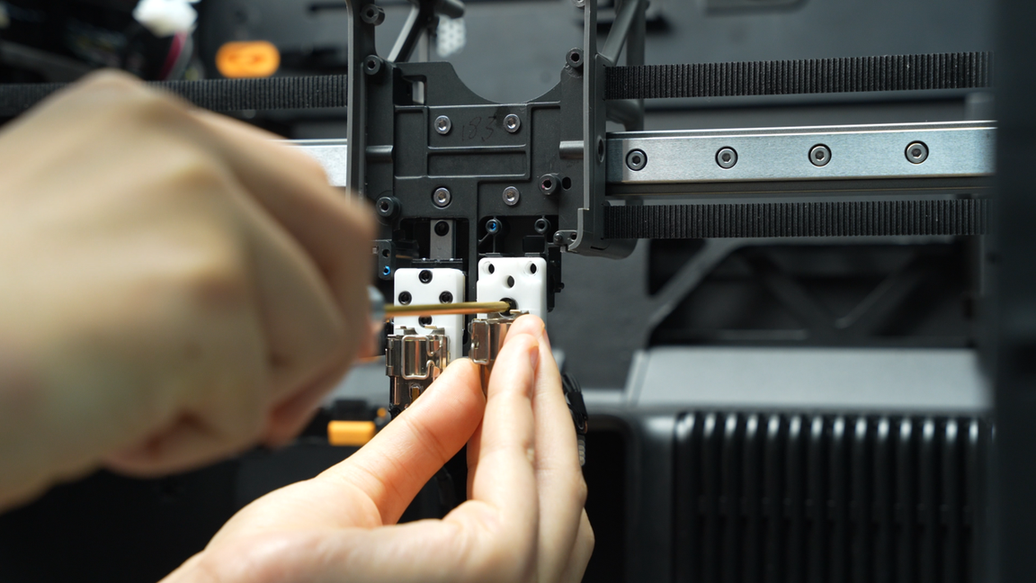
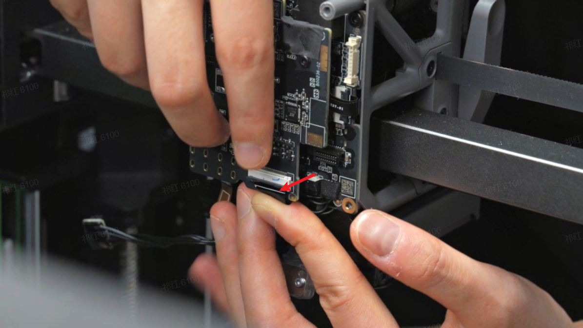
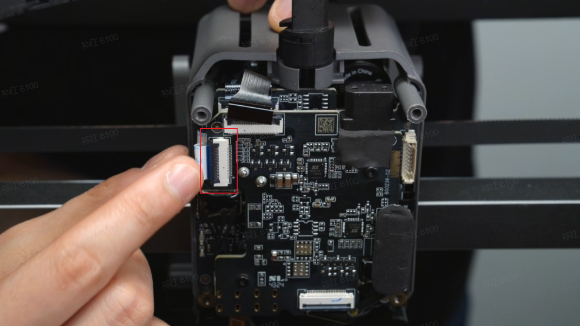
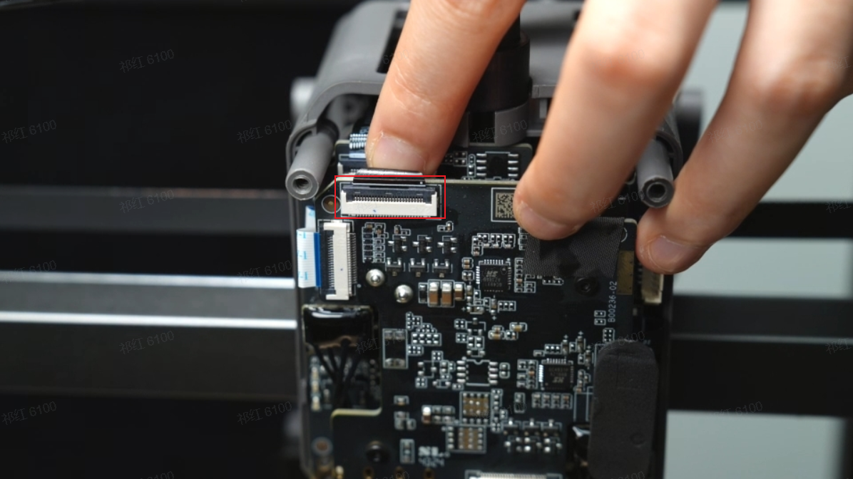
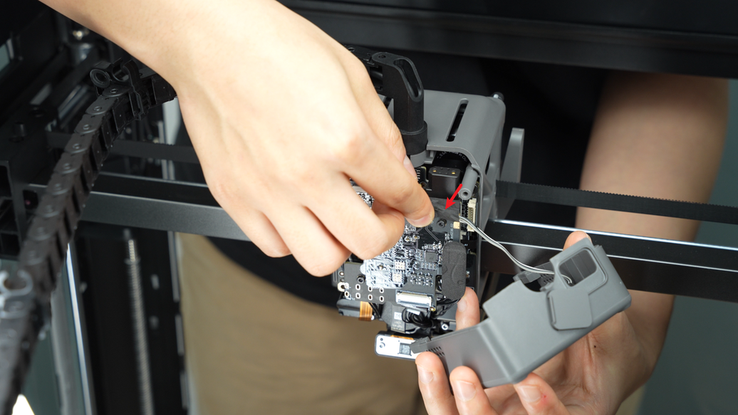
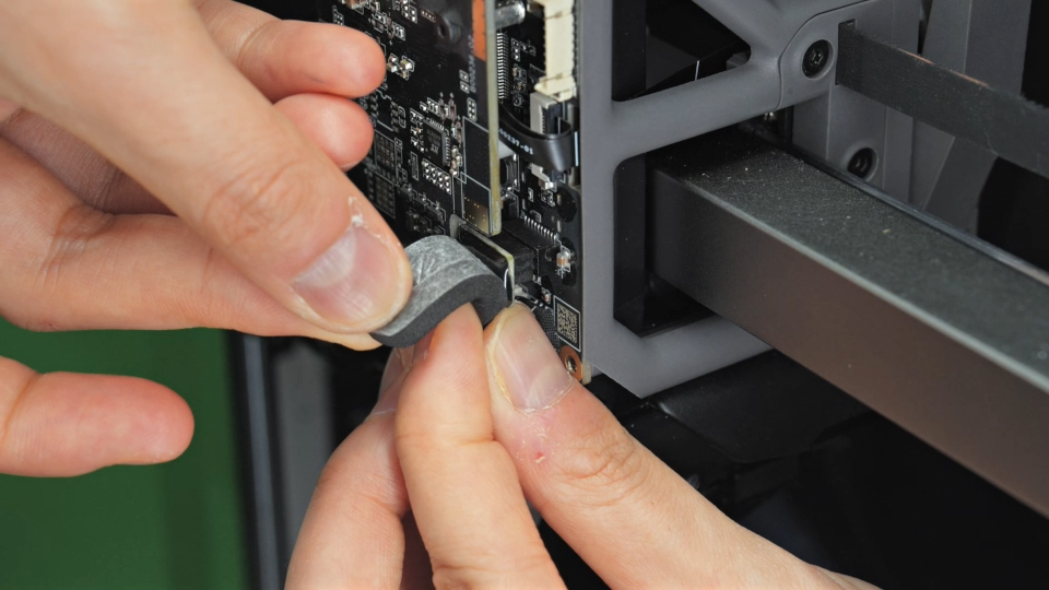
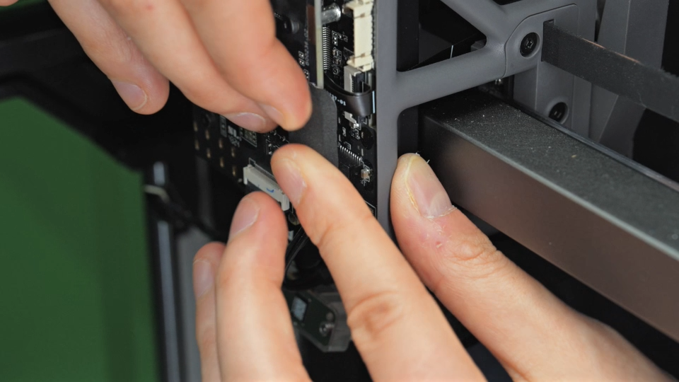
Important Reminder
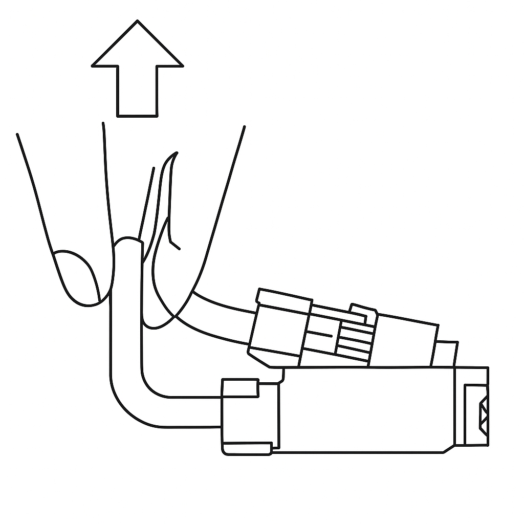
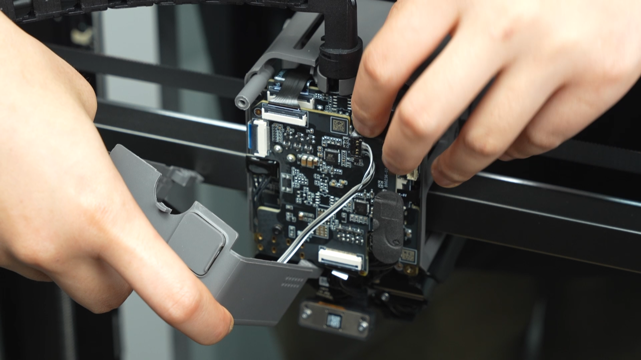
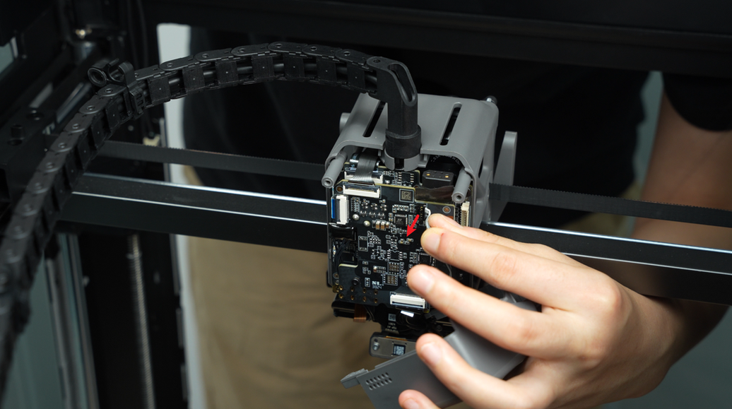
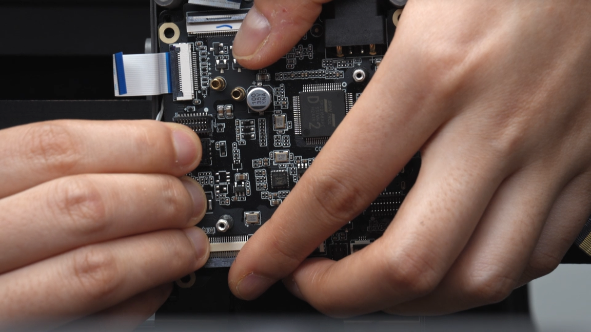
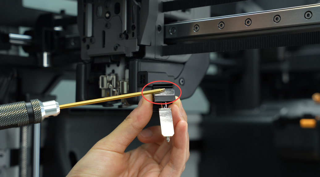
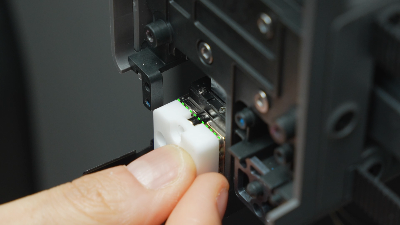
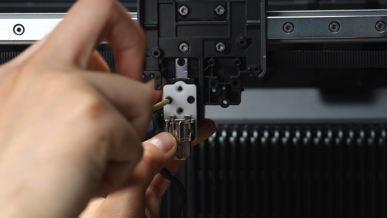
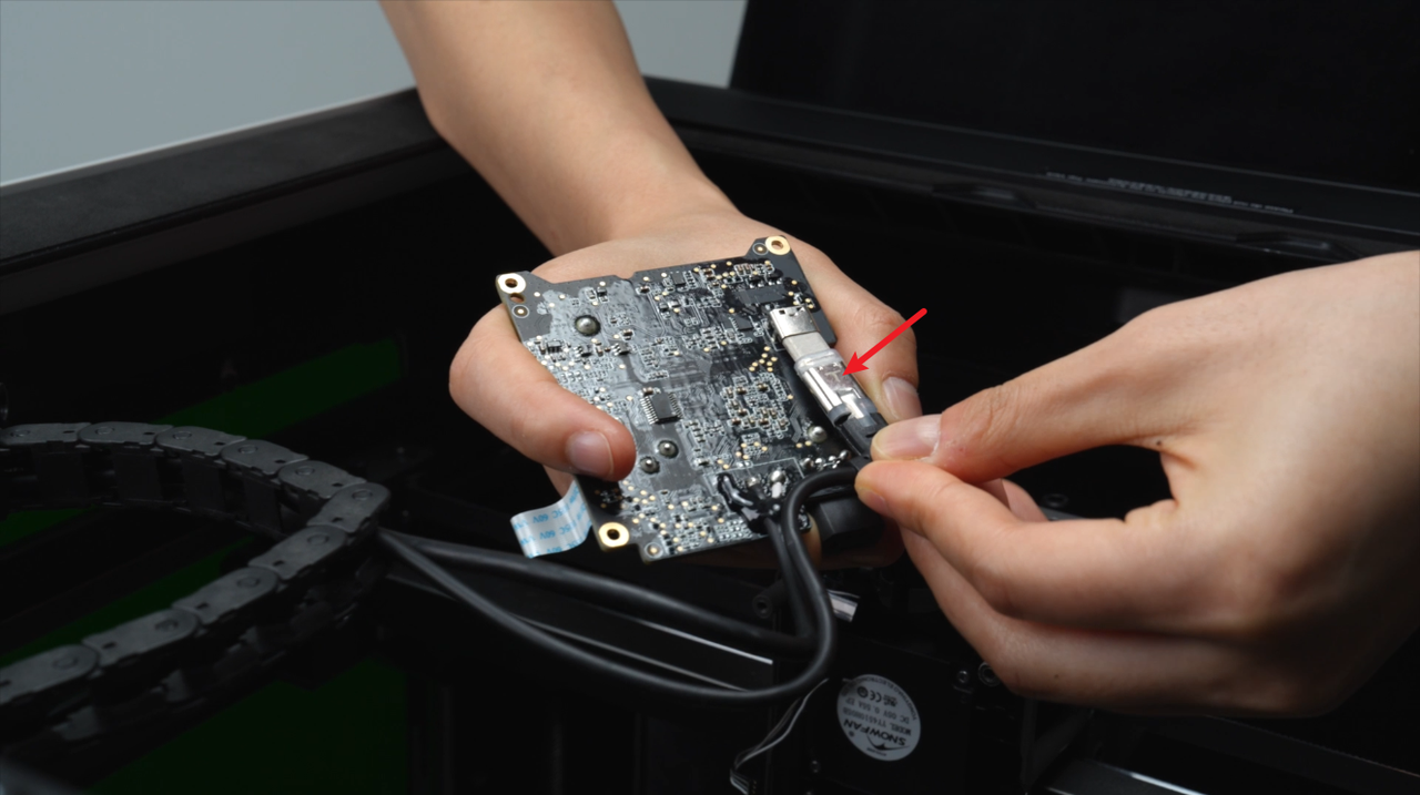
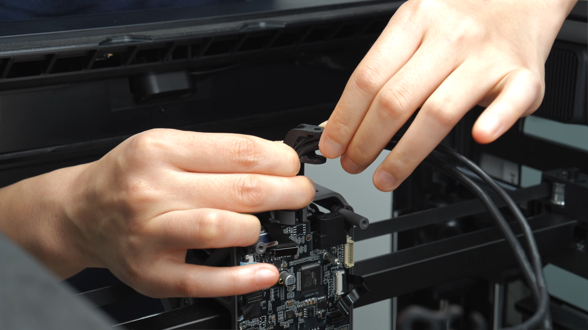
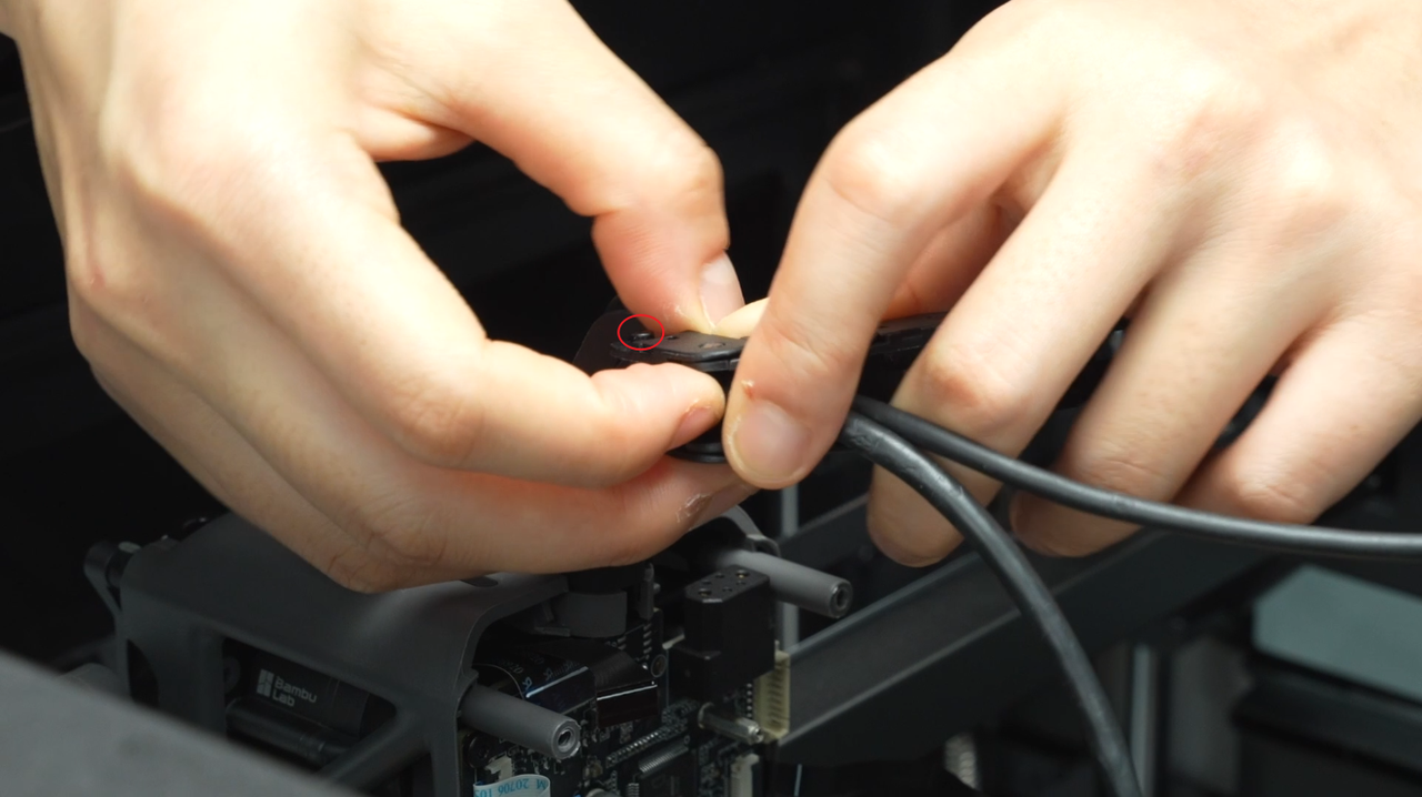
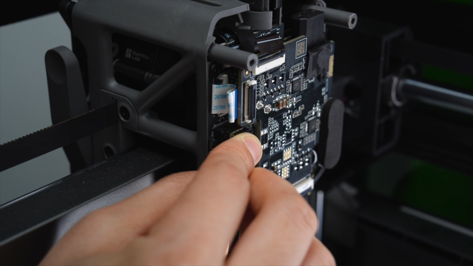
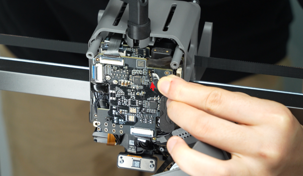
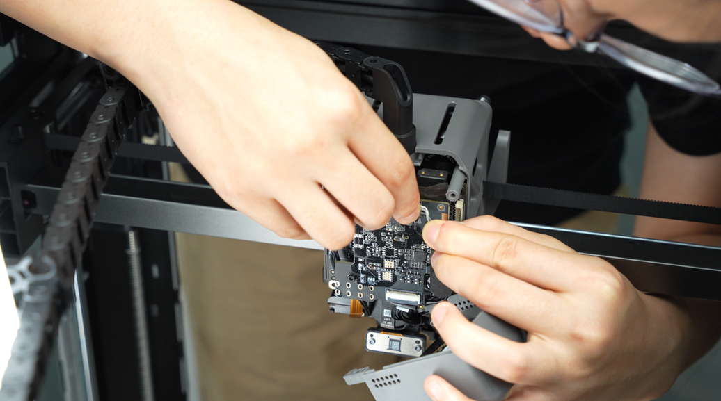
The eddy sensor coil connectors on the H2D feature this compact connector design. When removing the connector, please hold the base of the connector with your hand and lift straight up, perpendicular to the PCB surface, to unlock it. Never apply force in the horizontal direction to avoid damaging the connector.
¶ Applicable models of printers
H2D
¶ When to use?
This article provides guidance and precautions for disassembly and assembly of the H2D toolhead. The disassembly and assembly of replaceable accessories involved in this disassembly process can also be handled by referring to this article.
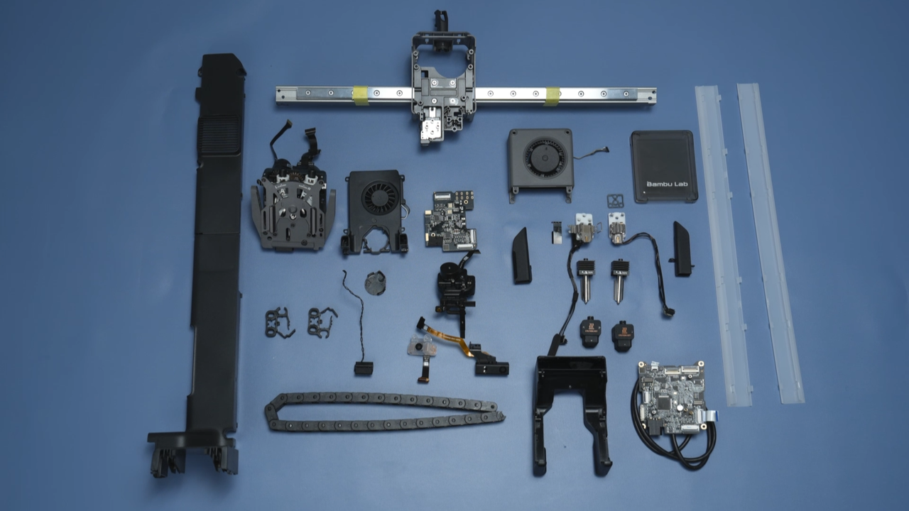
¶ Parts List
The following are the after-sales single item materials that this guide will involve.
| PTFE tube | |
| Toolhead front cover | Silicone sock for hotend |
| Hotend | Part cooling fan air duct |
| Part cooling fan | H2D Extruder connection board |
| Extruder unit | TH board FPC cable |
| H2D TH board | USB-C cable |
| Cooling fan for hotend | Cooling fan air duct for hotend |
| 2004 Lifting motor unit | Nozzle camera |
| Right hotend heating assembly | Left hotend heating assembly |
| Toolhead camera | Right eddy sensor |
| Toolhead carriage | Flow blocker magnet bracket |
¶ Safety Warning
IMPORTANT!
It's crucial to power off the printer before conducting any maintenance work, including work on the printer's electronics and tool head wires. Performing tasks with the printer on can result in a short circuit, leading to electronic damage and safety hazards.
During maintenance or troubleshooting, you may need to disassemble parts, including the hotend. This exposes wires and electrical components that could short circuit if they contact each other, other metal, or electronic components while the printer is still on. This can result in damage to the printer's electronics and additional issues.
Therefore, it's crucial to turn off the printer and disconnect it from the power source before conducting any maintenance. This prevents short circuits or damage to the printer's electronics, ensuring safe and effective maintenance. For any concerns or questions about following this guide, we recommend submitting a technical ticket regarding your issue and we will do our best to respond promptly and provide the assistance you need.
¶ Assemblies List
The assemblies require additional disassembly:
- Dual extruder unit
- Toolhead carriage
- 2004 Lifting motor unit
¶ Tools and materials needed
-
H2.0 Allen key (with magnet)
-
H1.5 Allen key (with magnet)
-
Tweezers
-
240 minutes
It is highly recommended that you purchase two high-quality Allen keys, which will significantly improve your repair experience. If the screwdriver loses its magnetism, you can remagnetize it using the magnet on the hotend.
¶ Video Guide
H2D Toolhead Assembly Guide
H2D Toolhead Disassembly Guide
¶ Disassembly Guide
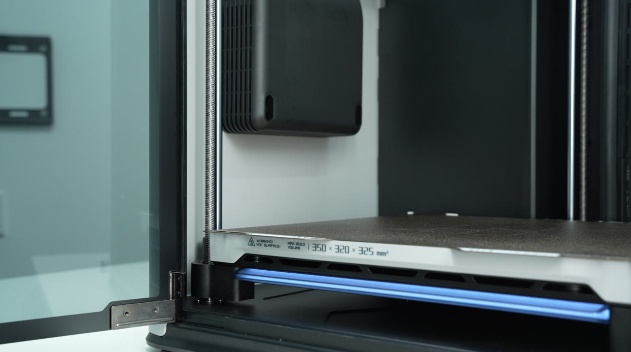
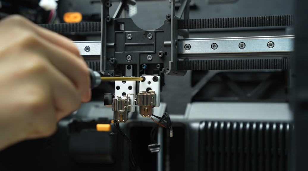
¶ Step 1:Lower the heatbed
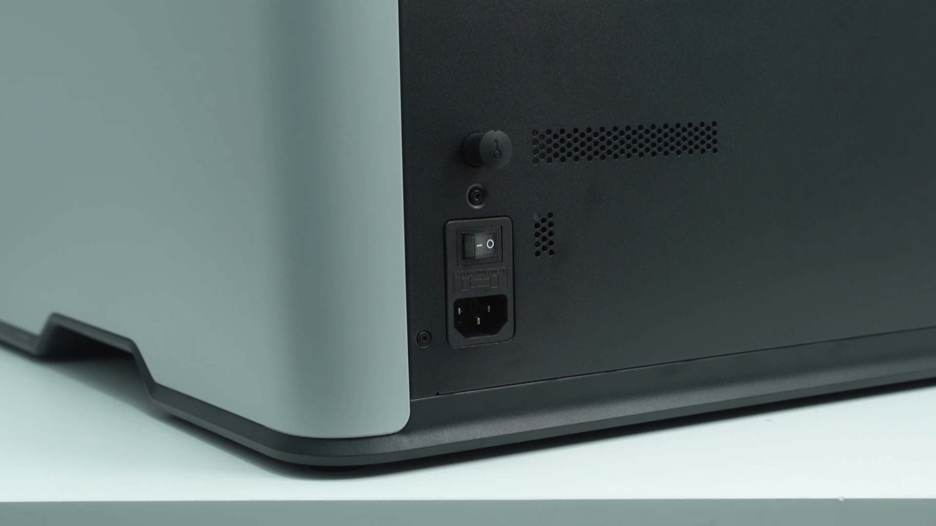
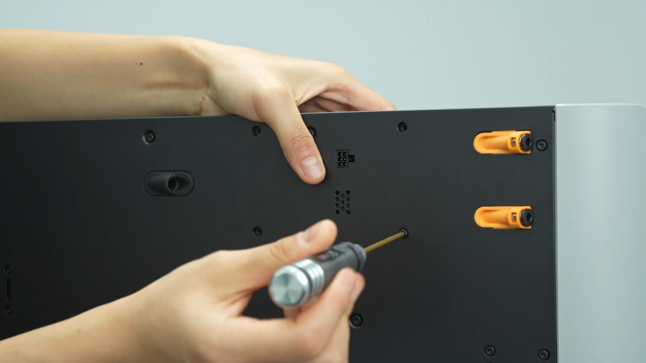
Lower the heatbed on the screen and ensure that the hotend is at room temperature, then power off the printer.
 |
 |
 |
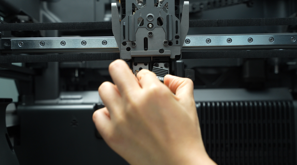
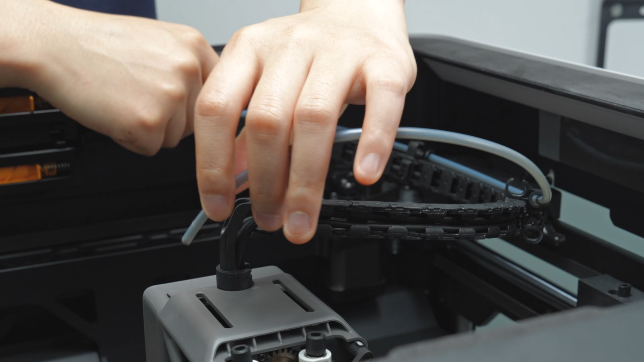
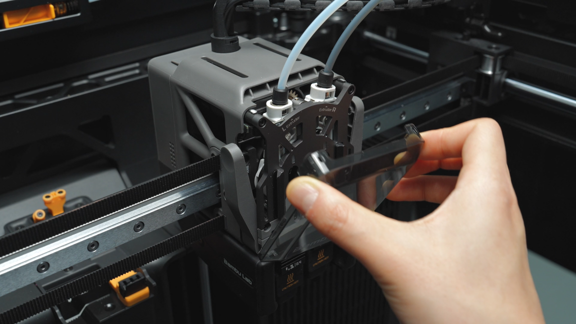
¶ Step 2: Remove the PTFE tube inside and on the back of the chamber
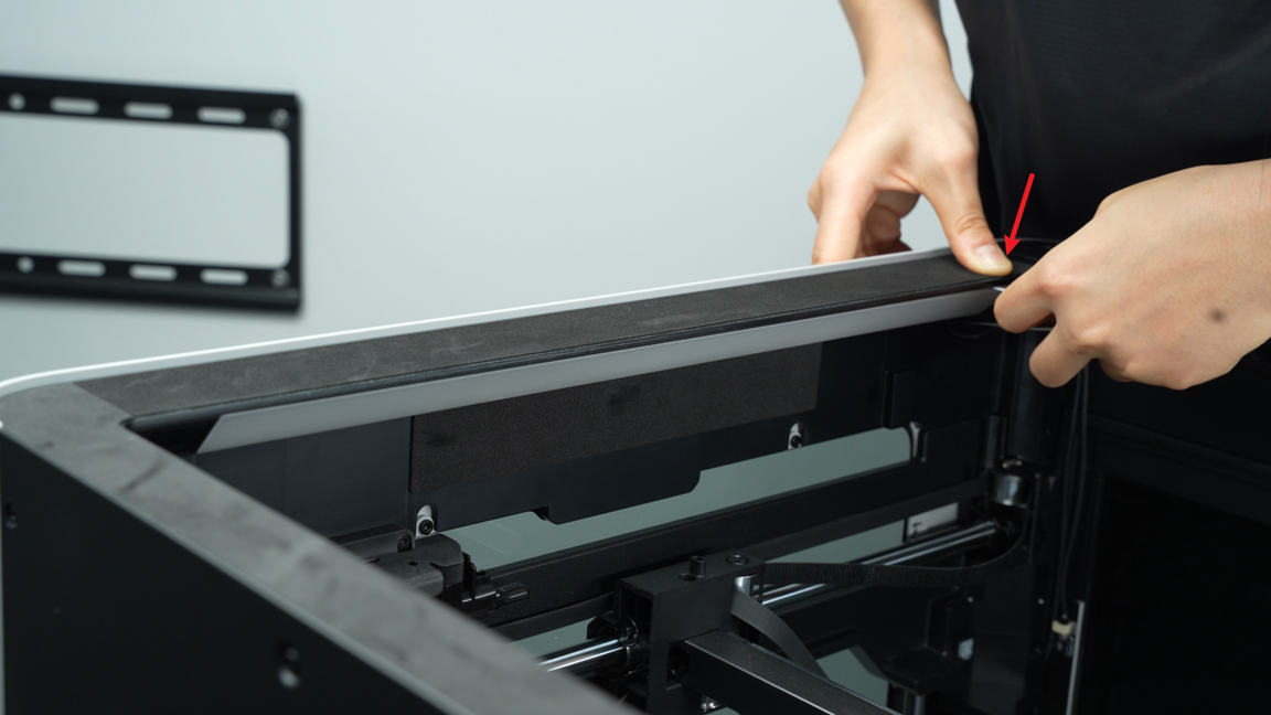
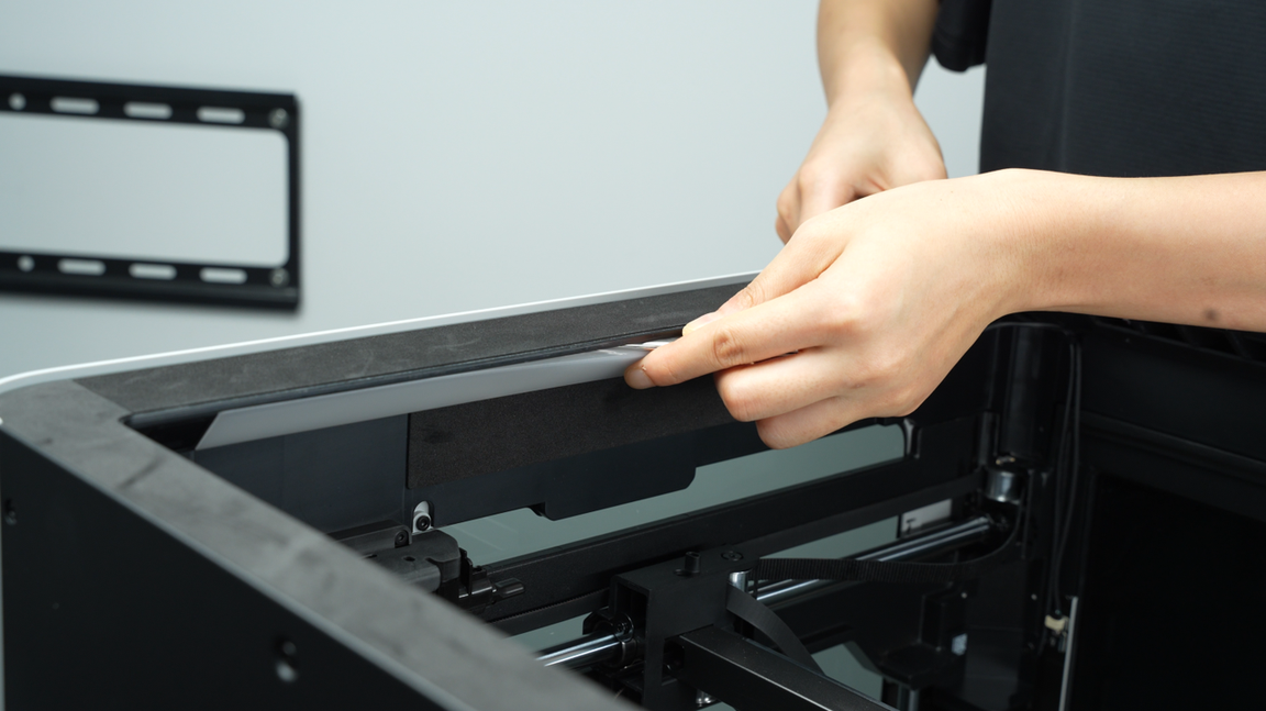
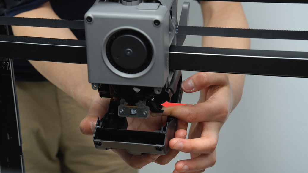
Pinch the top of the toolhead front cover and lift the toolhead front cover upward.
 |
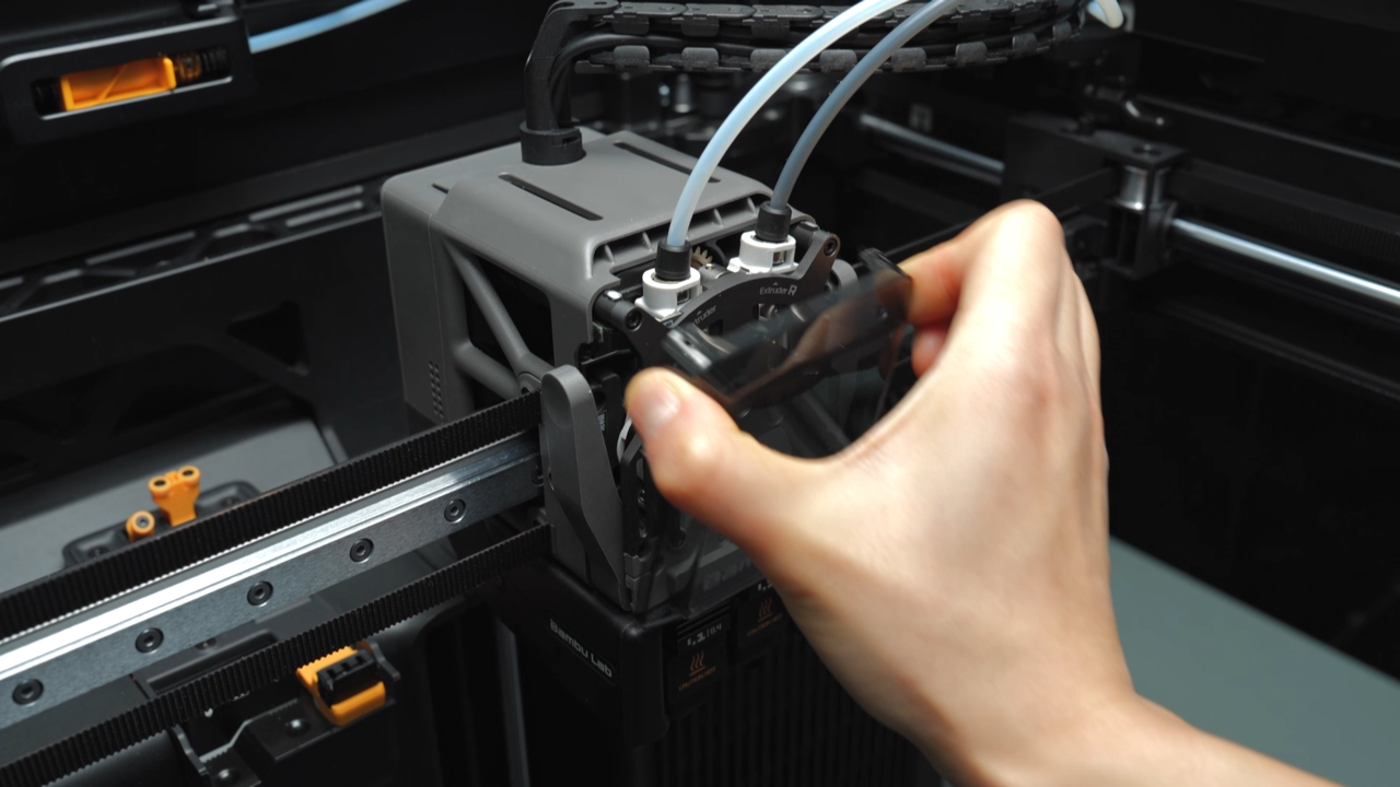 |
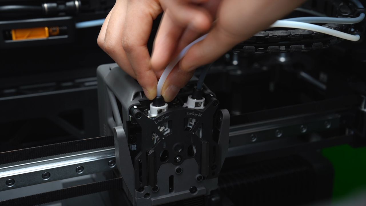
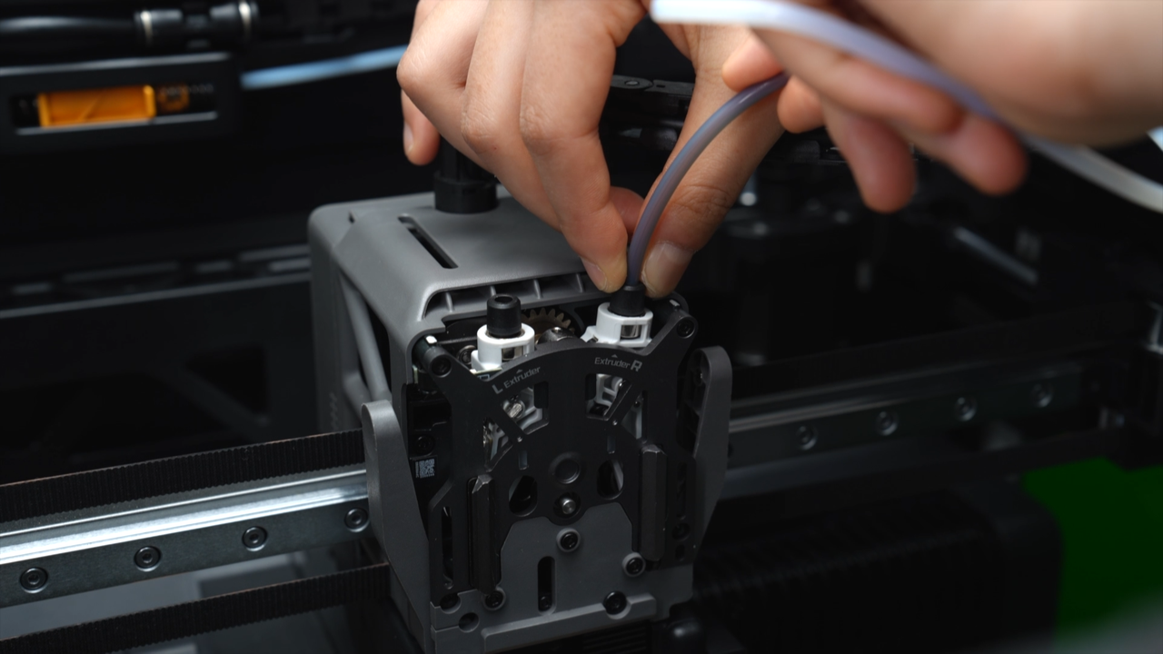
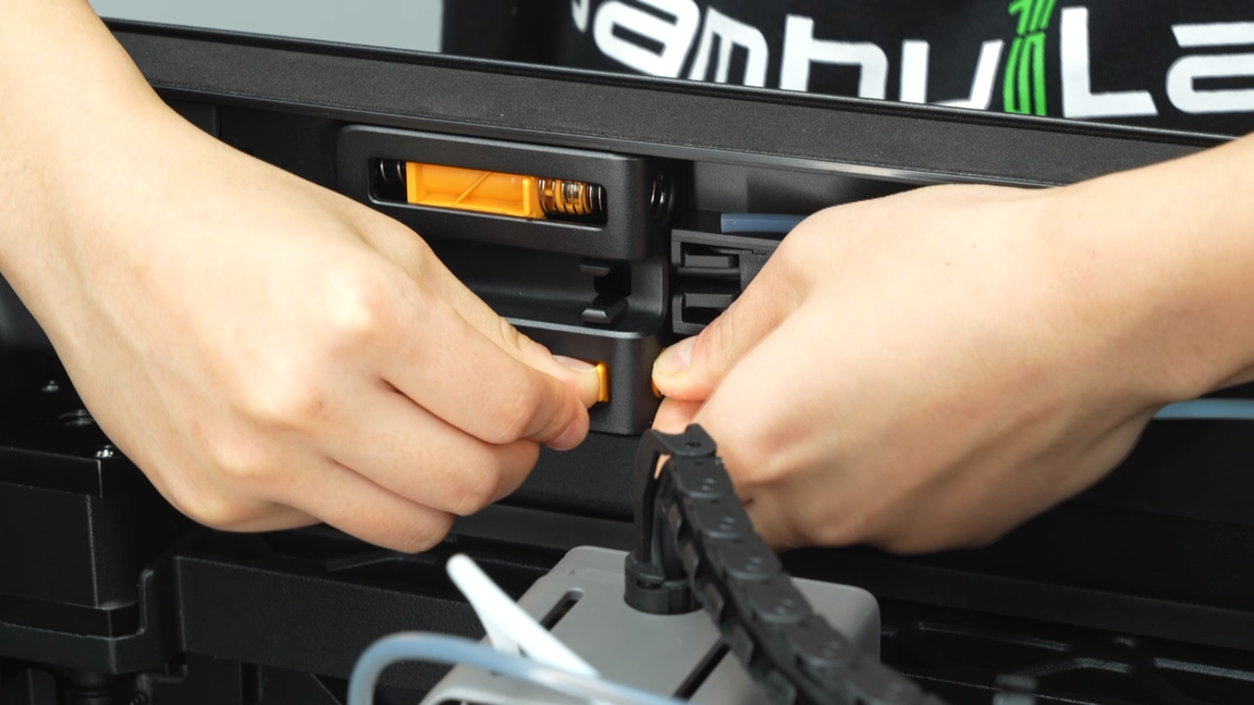
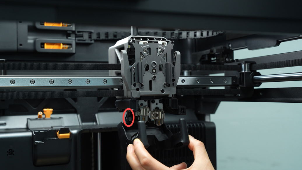
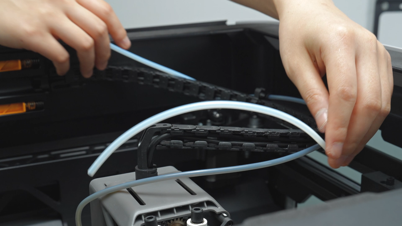
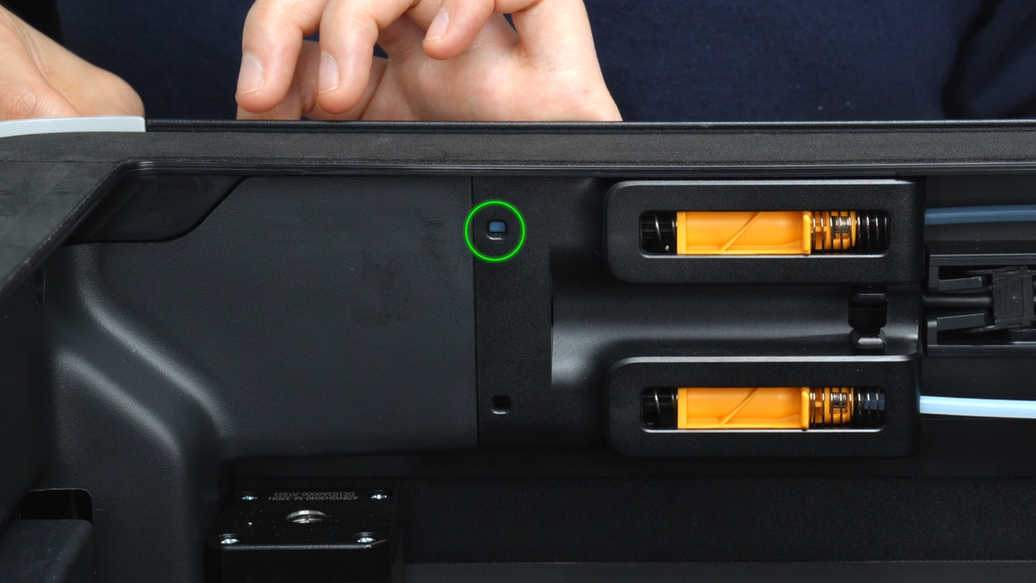
Press the black outer ring to unlock the two connectors above the extruder and at the upper and lower ends of the buffer, and then pull out the two PTFE tubes on the left and right. The connector of the buffer can be pushed to the right for easy unlocking.
 |
 |
 |
 |
 |
 |
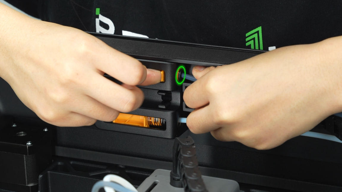
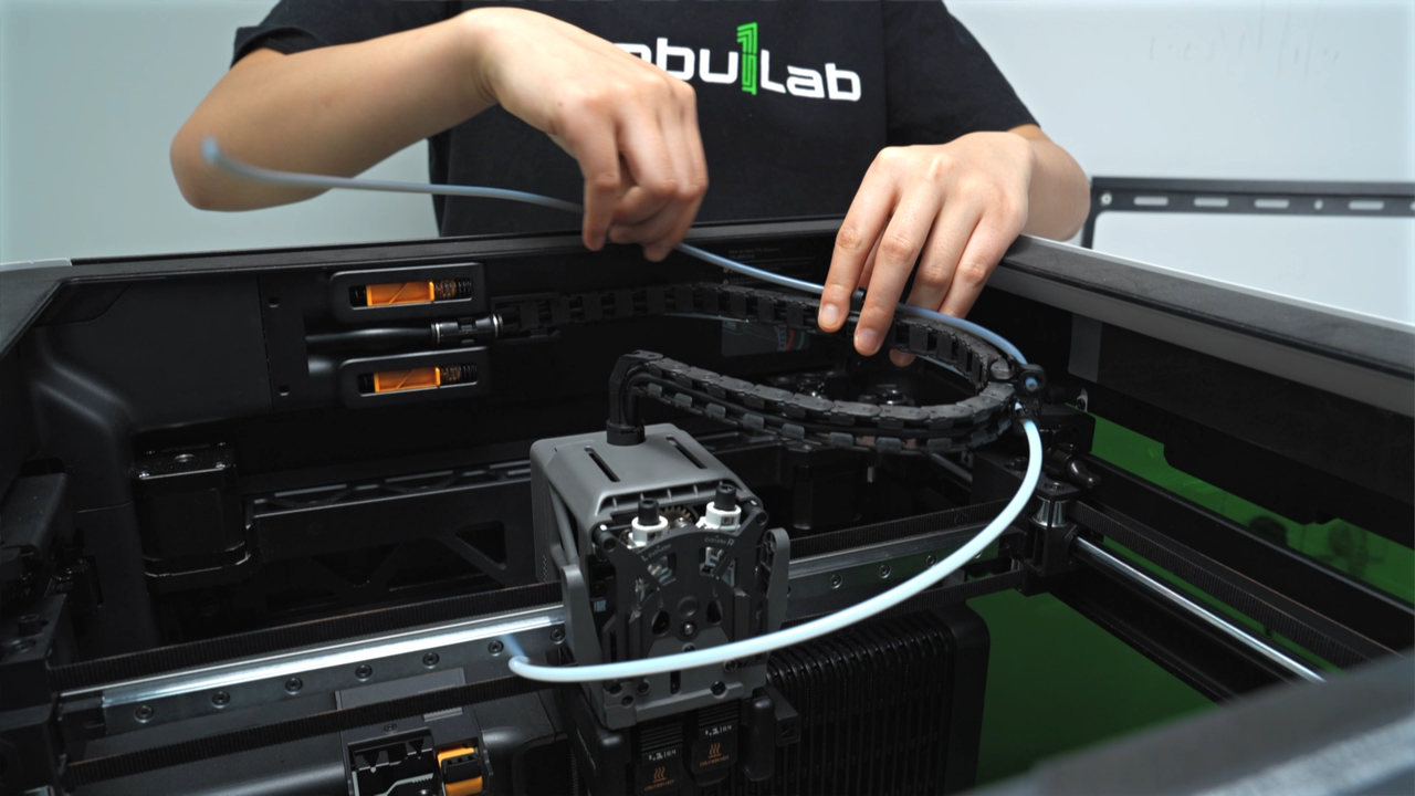
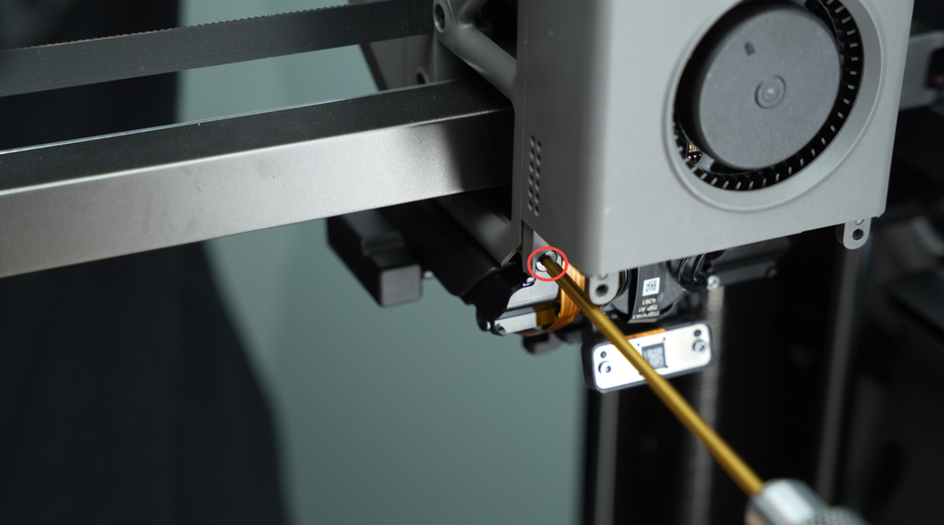
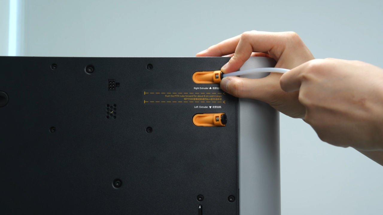
Next, unlock the pneumatic connector at the feed coupler on the back of the printer and remove the PTFE tube.
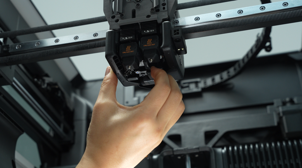
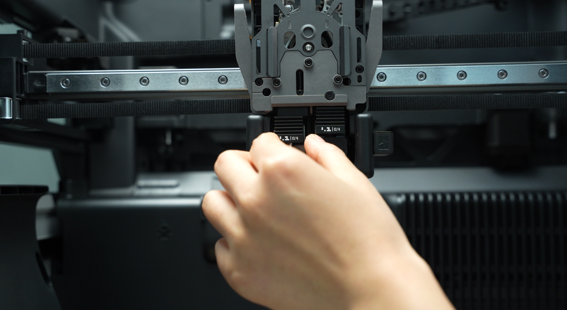
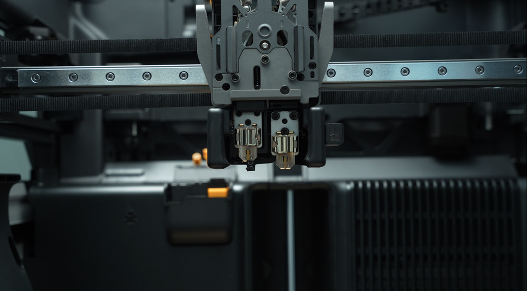
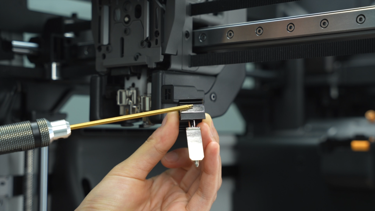
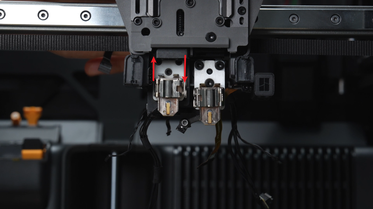
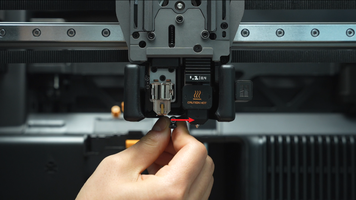
¶ Step 3 - Remove the left and right hotends
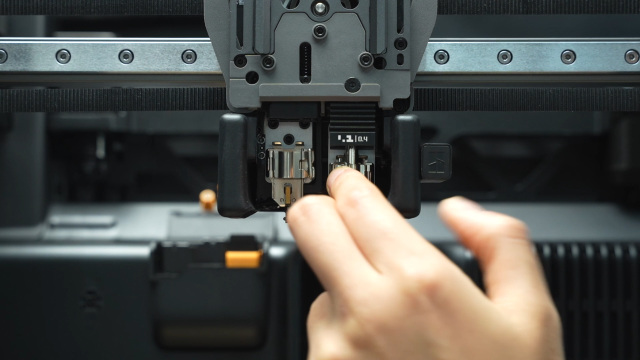
The flow blocker is located on the lifting rod. By moving the rod, the flow blocker will move left and right. If you need to remove a hotend and the flow blocker is blocking the hotend, you must first move the flow blocker connecting rod to move the flow blocker away before removing it to prevent the flow blocker from being accidentally bent when removing the hotend. When moving, the flow blocker may not be moved into place at once due to the tilt limit of the connecting rod. At this time, you need to make a rough move and then make a fine adjustment to ensure that the flow blocker is completely in place.
 |
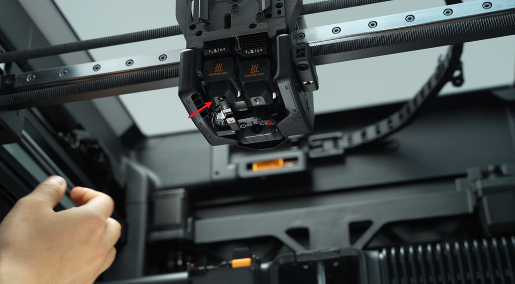 |
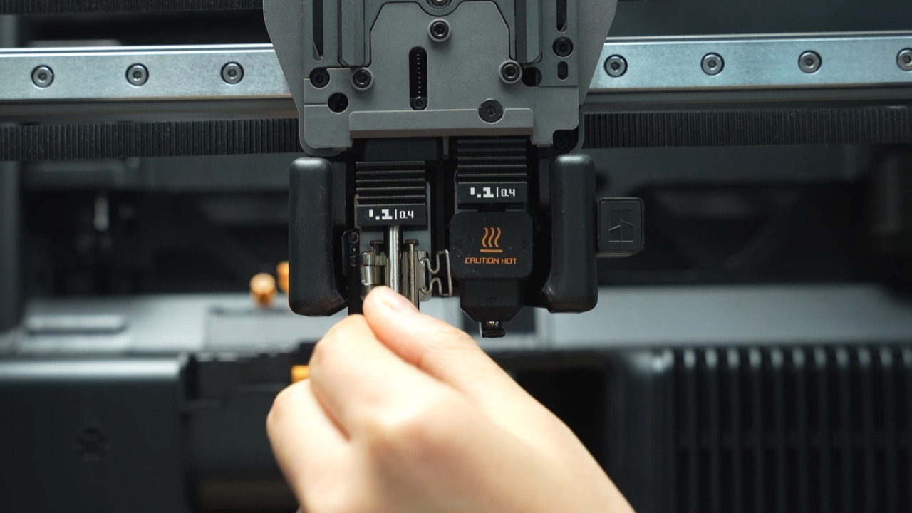
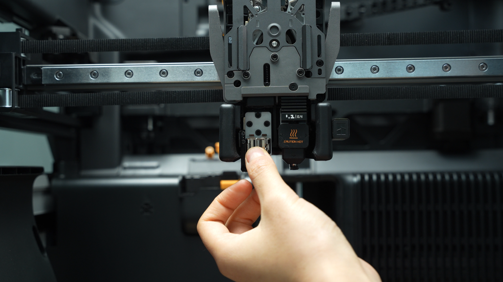
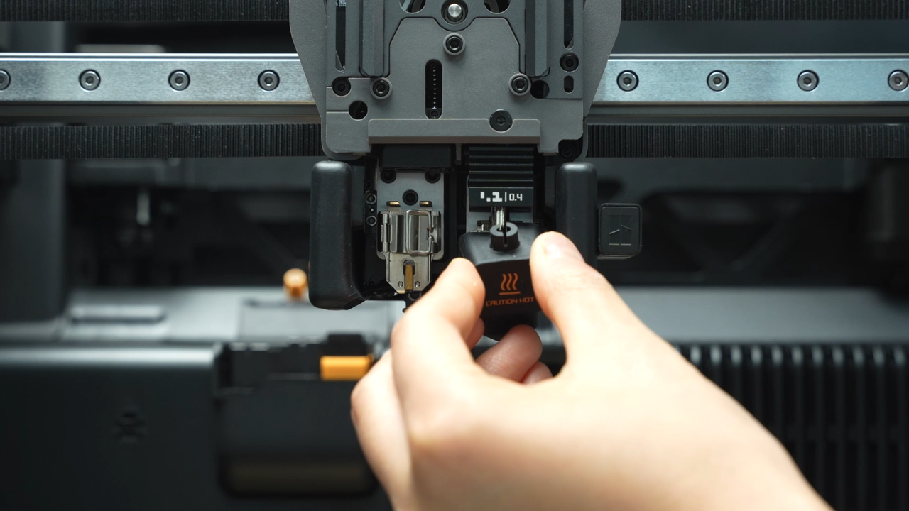
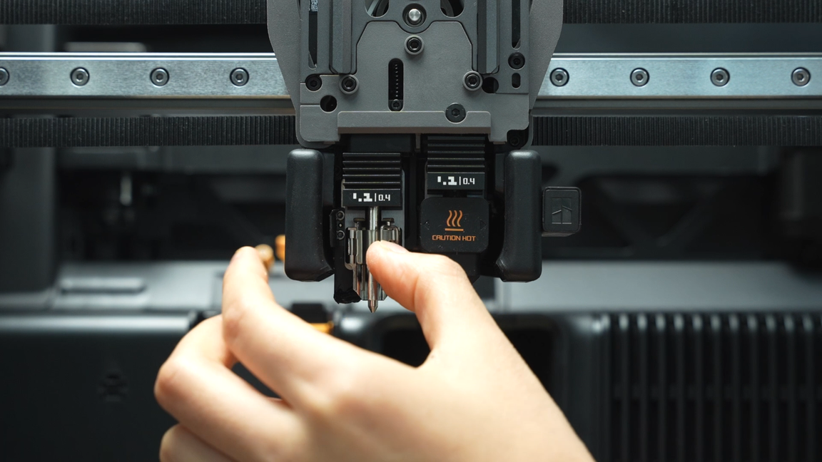
Remove the silicone sock for hotend that is not blocked by the flow blocker, unlock the buckle to remove the hotend, and pre-fasten the buckle of the heating assembly.
 |
 |
 |
 |
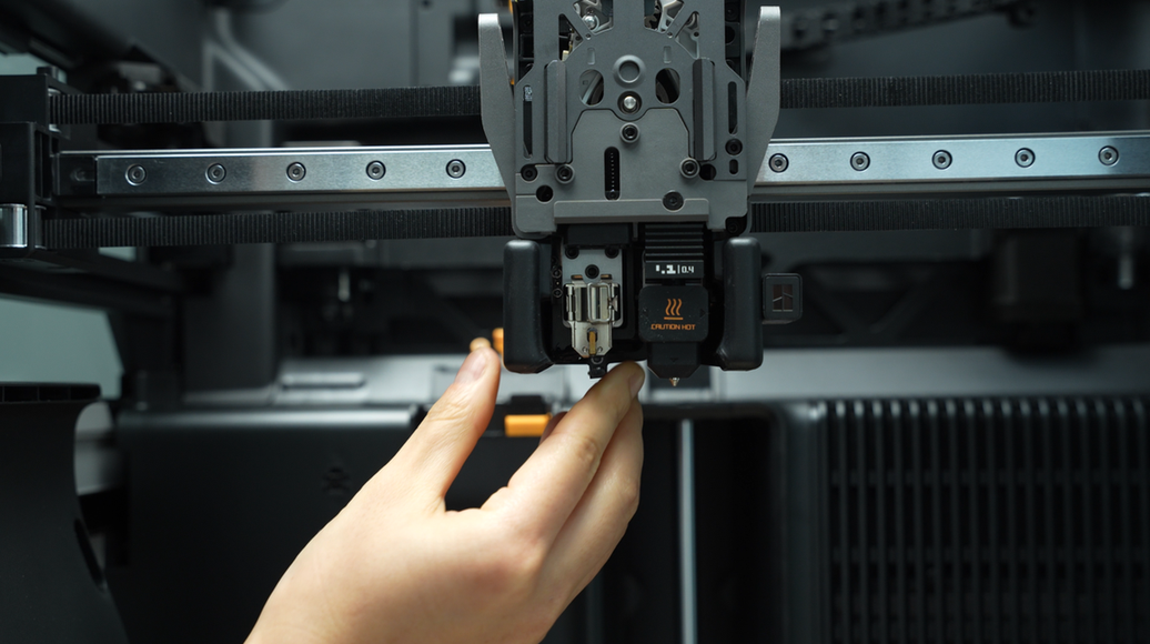
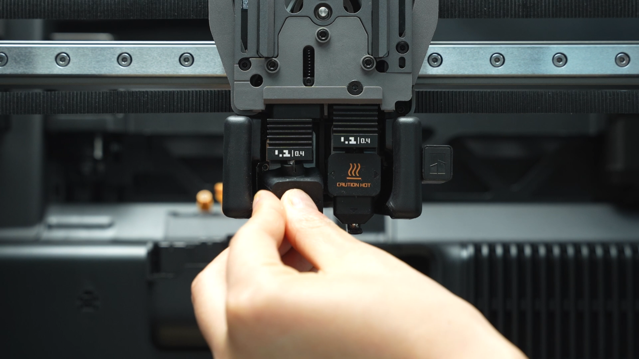
Move the flow blocker connecting rod to move the flow blocker to the other side, remove the silicone sock of the remaining hotend, unlock the buckle to remove the hotend, and pre-fasten the buckle of the heating assembly.
 |
 |
 |
 |
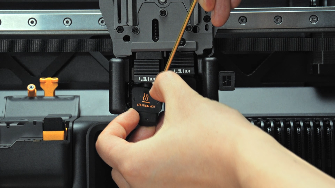
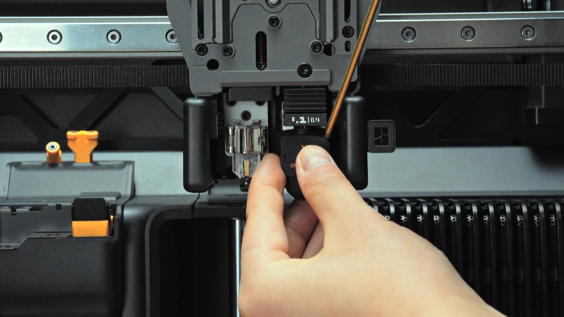
After removing the hotends, you can magnetize the allen key by attaching it to the magnet on the hotend, which will facilitate the subsequent screw removal.
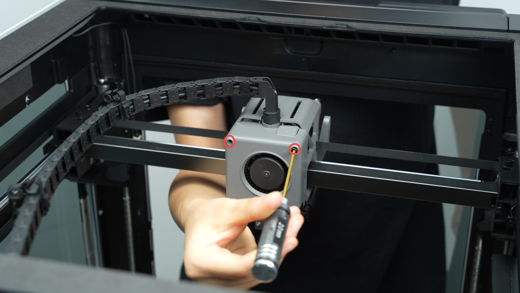
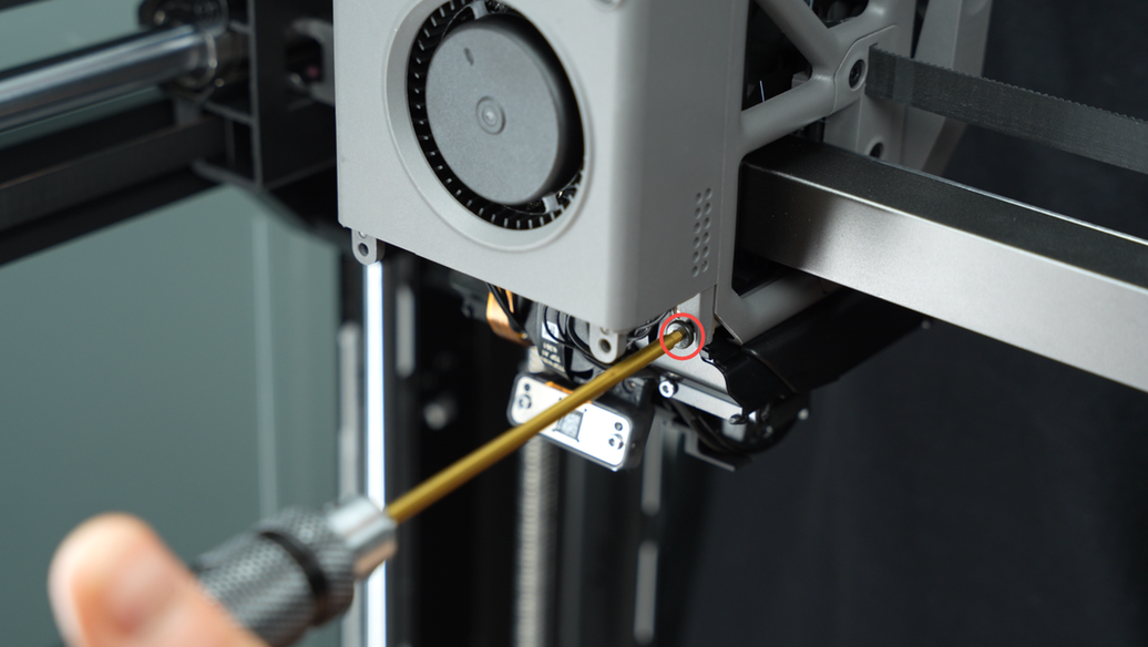
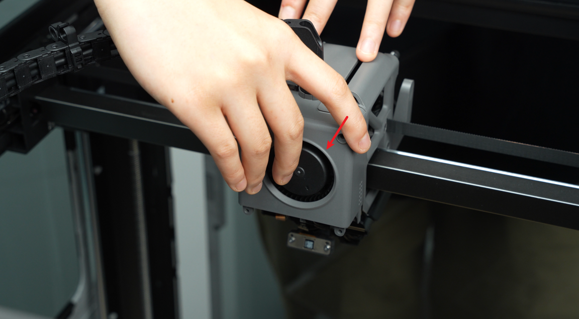
¶ Step 4 - Remove the part cooling fan air duct
Remove the 4 screws of the part cooling fan air duct and remove the part cooling fan air duct downwards. You can carefully pull the air duct downwards as shown in the figure.
 |
 |
 |
 |
 |
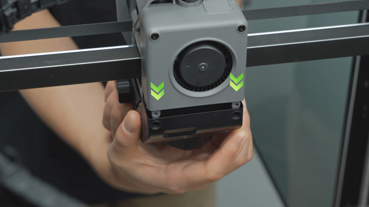 |
¶ Step 5 - Removing the part cooling fan
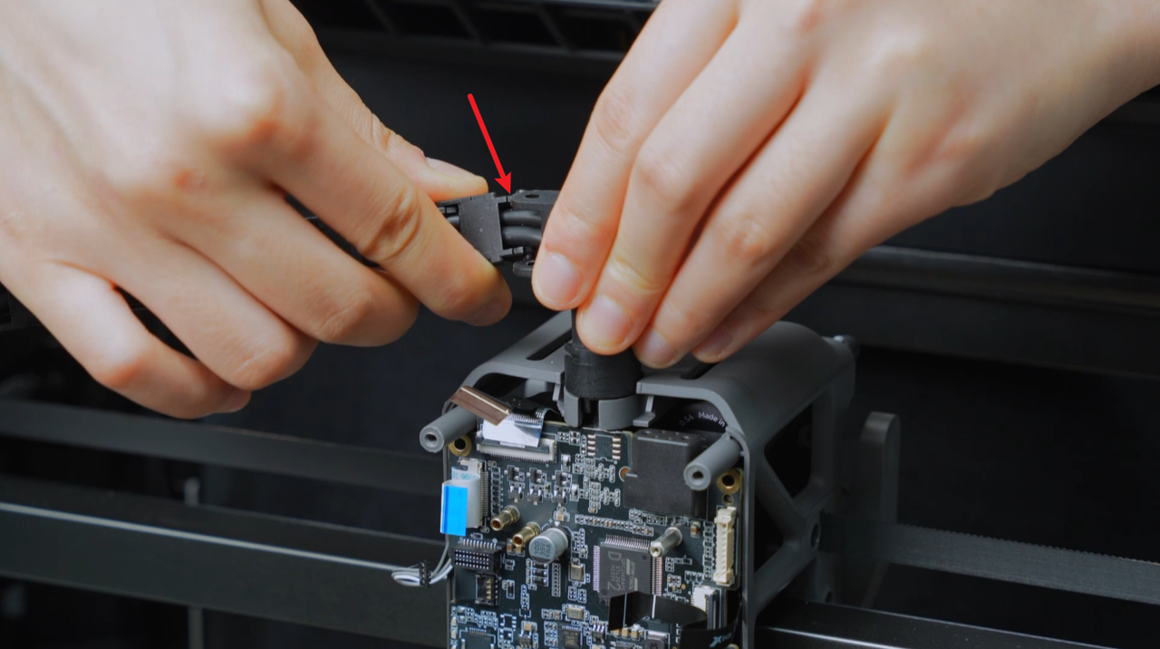
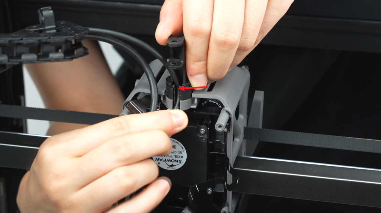
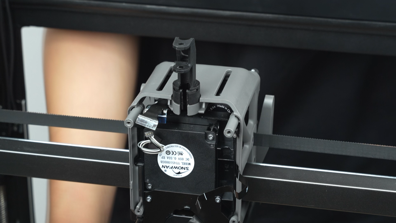
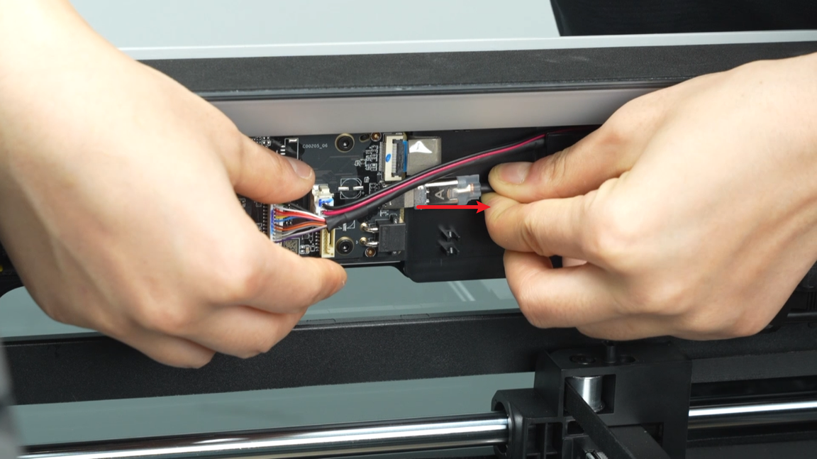
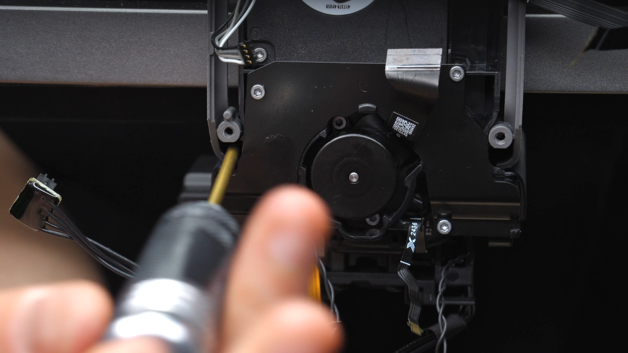
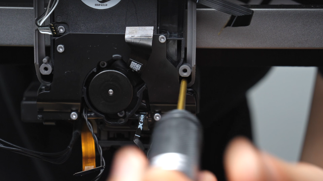
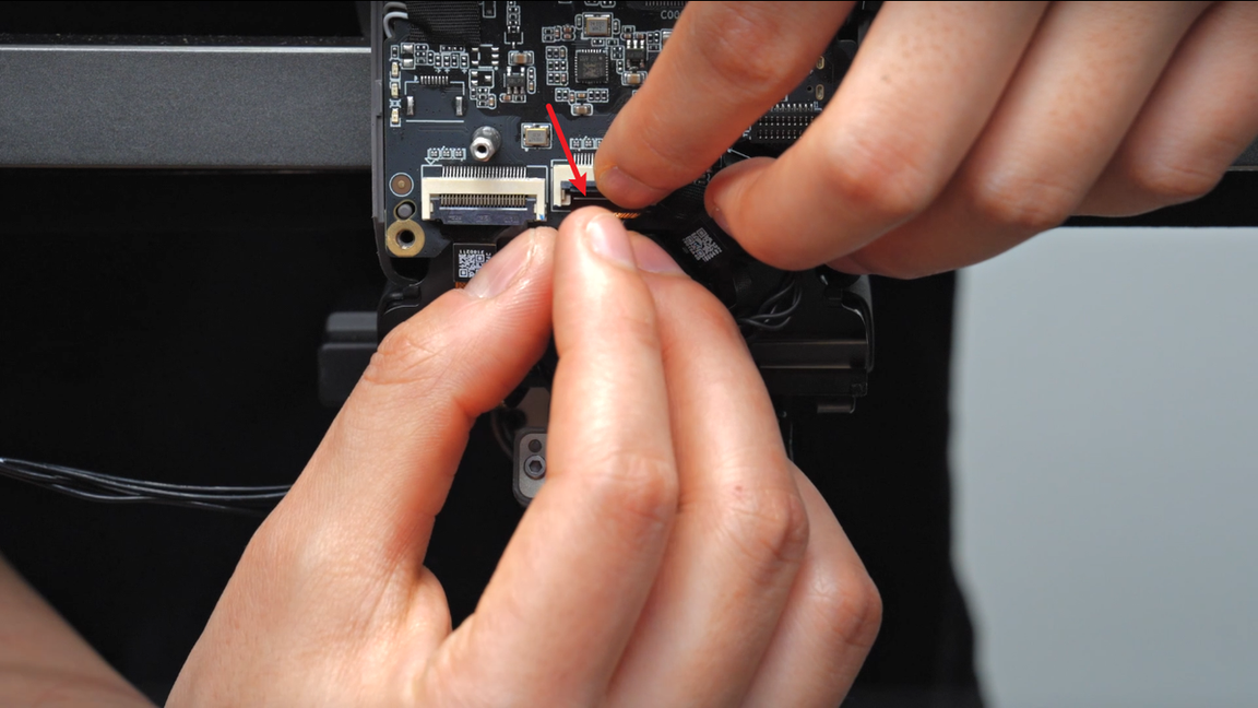
Remove the 4 screws of the part cooling fan, tear off the auxiliary tape of the plug, and unplug the plug. You can leave the removed tape on the power board to facilitate subsequent installation.
Please note that this type of plug should be lifted diagonally away from the plane, rather than pulled along the direction of the cable. Follow the video instructions to avoid damaging the plug.
 |
 |
 |
 |
 |
 |
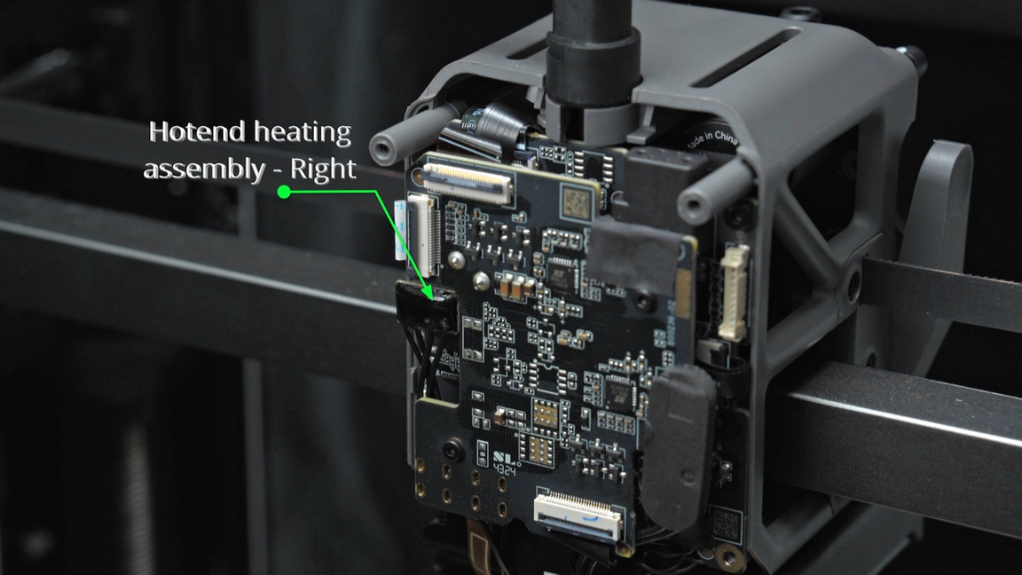
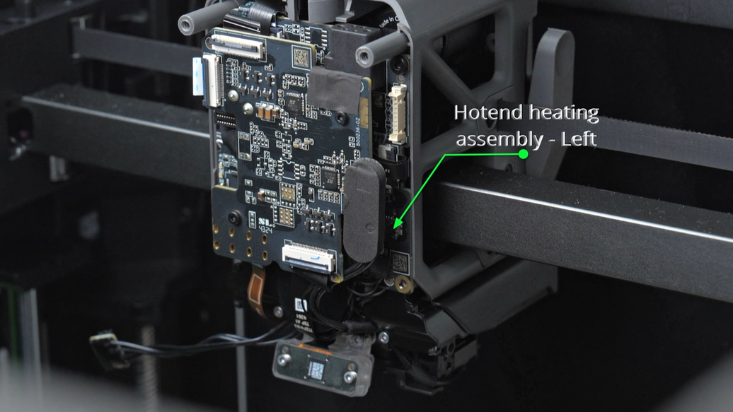
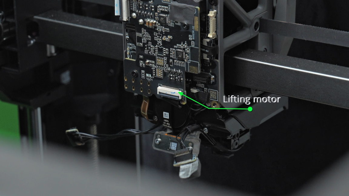
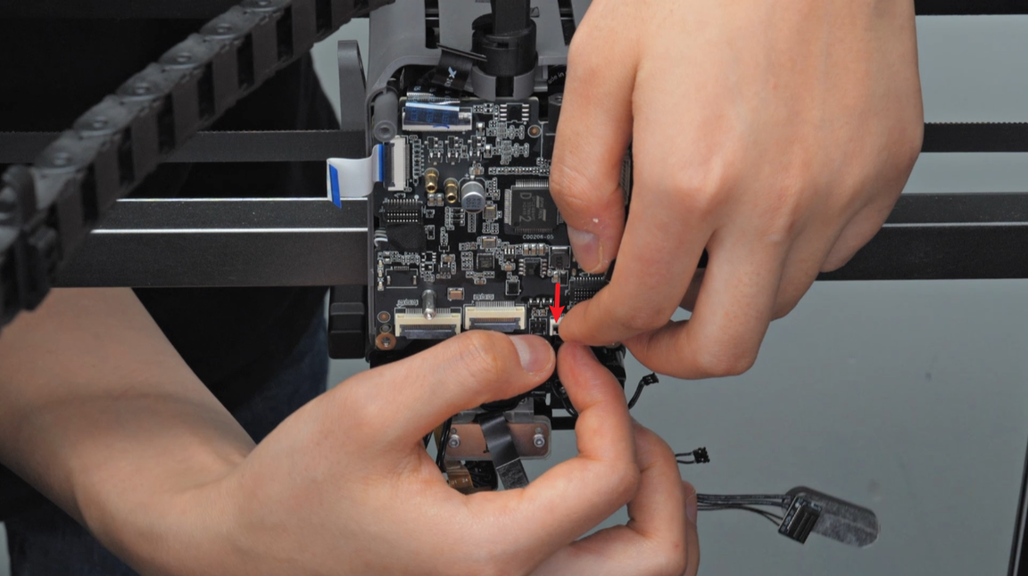
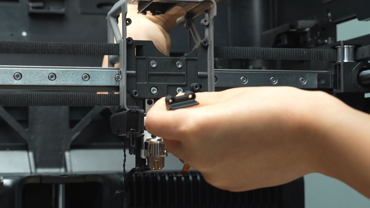
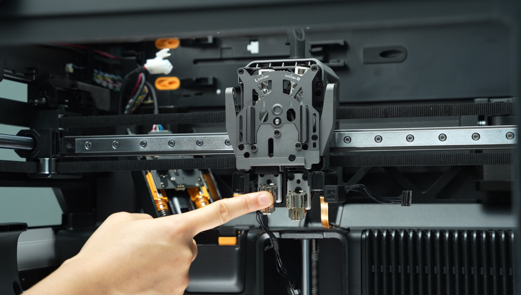
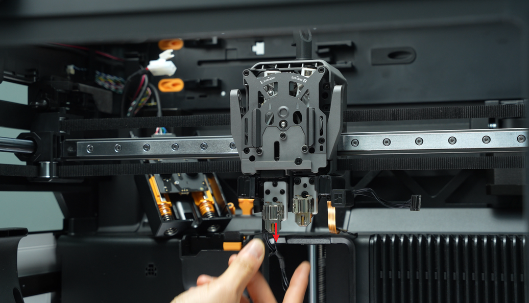
¶ Step 6 - Unplug the plugs and remove the TH connection board
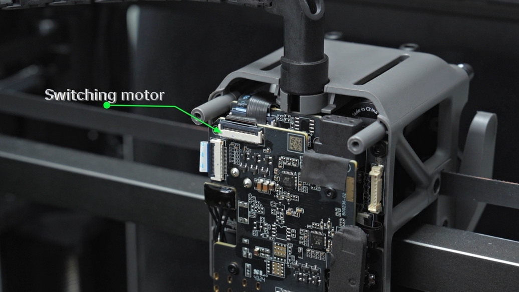
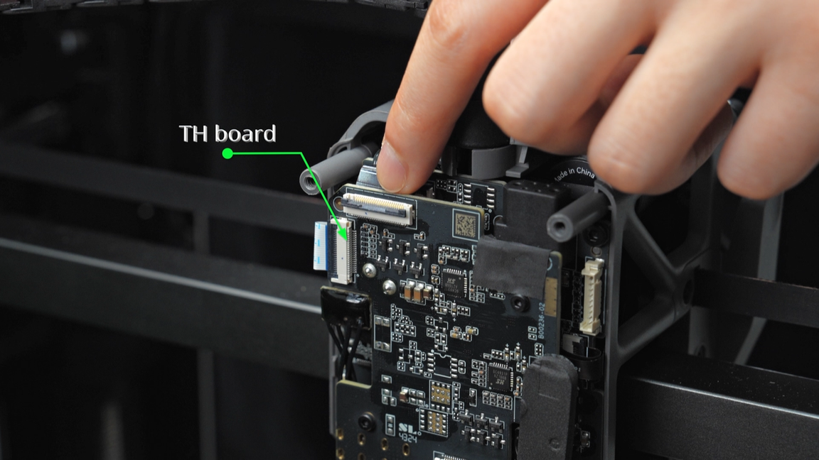
Disconnect the switching motor plug, TH board plug, right hotend heating assembly plug, left hotend heating assembly plug along with the foam pad (the left hotend heating assembly plug is located on the TH board, the foam pad is located on the TH connection board), and the lifting motor plug in sequence from the TH connection board.
Please note that the FPC cables are secured by clips, you need to unlock the clips before pulling out the FPC cables.
 |
 |
 |
 |
 |
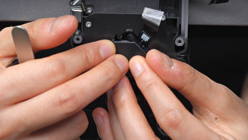
When tearing off the foam pad on the left hotend heating assembly plug, it is recommended to loosen the plug first, and then tear it off from the bottom up. This ensures the integrity of the foam pad.
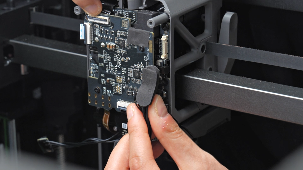
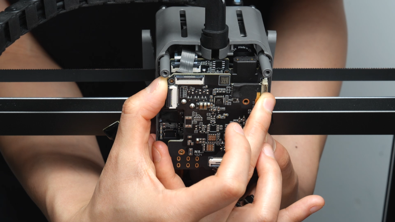
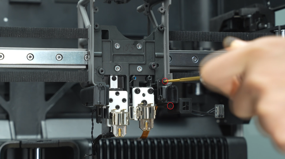
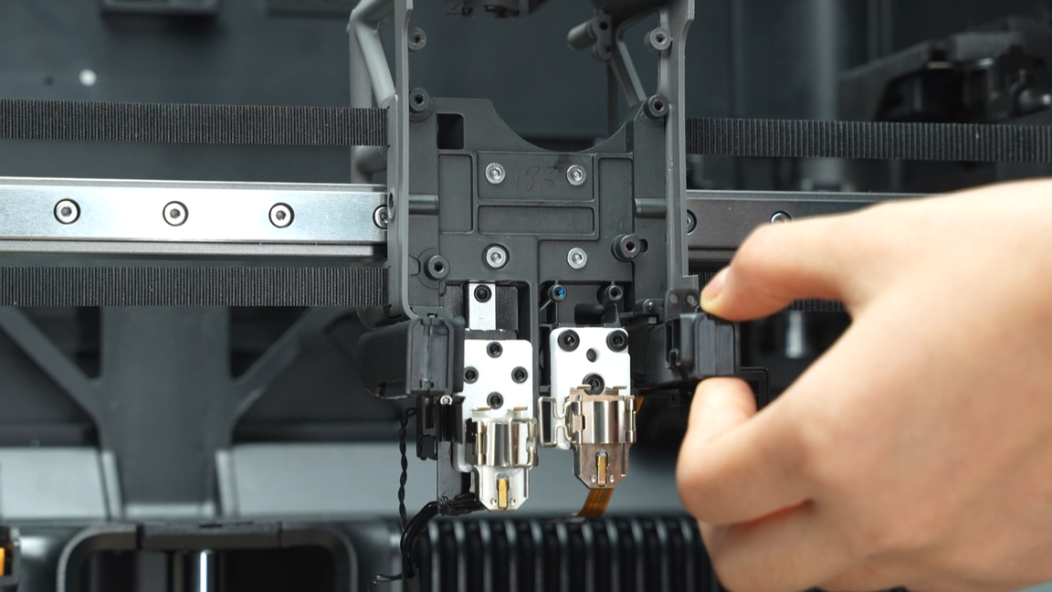
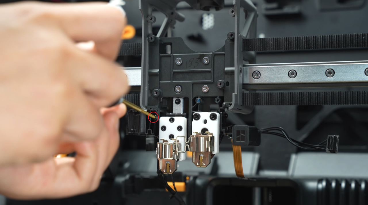
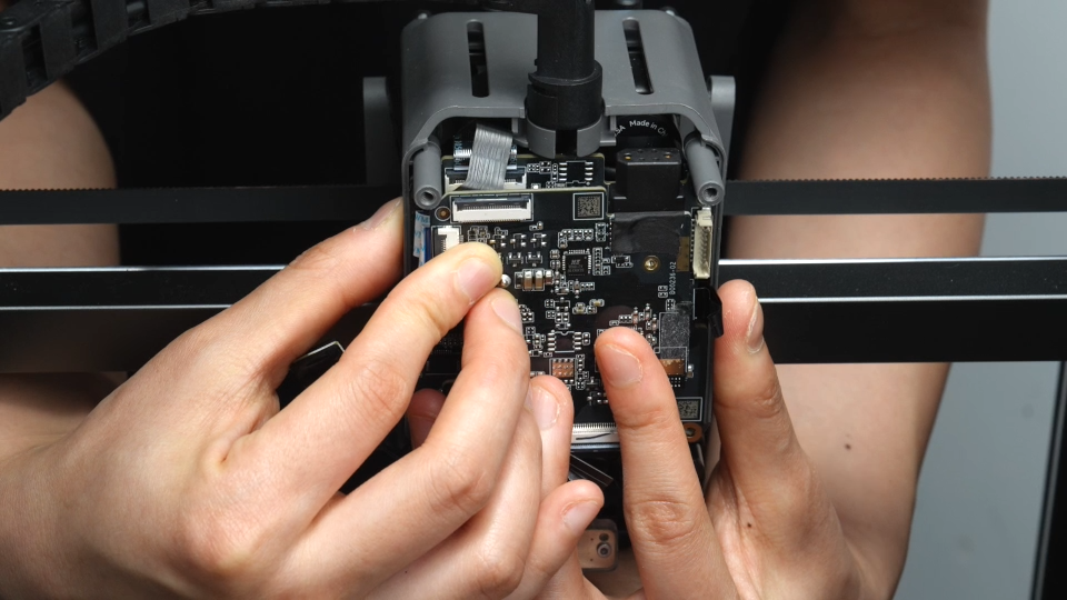
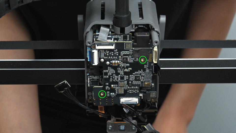
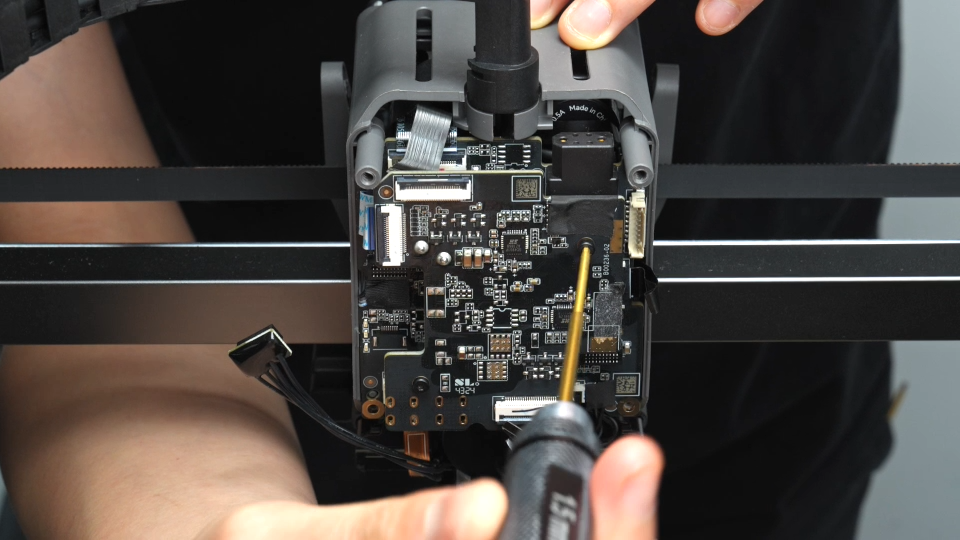
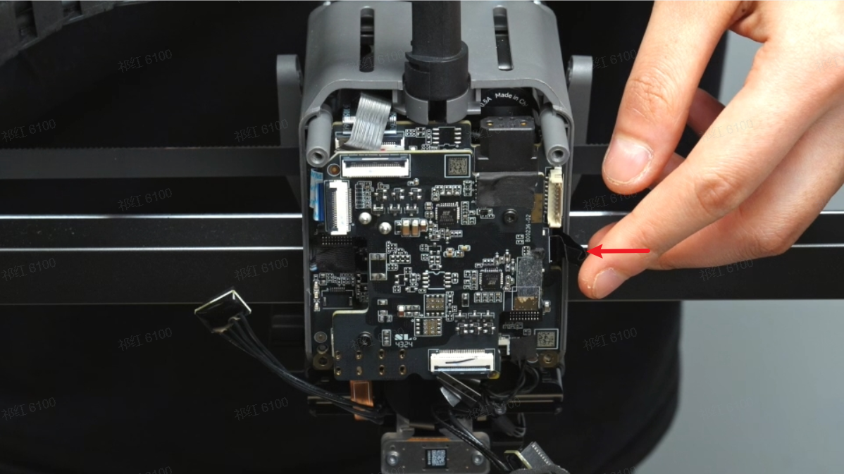
Unscrew the two fixing screws on the TH connection board, grip the sides of the connection board with one hand, and gently shake near the switching motor plug with the other hand to remove the TH connection board.
 |
 |
 |
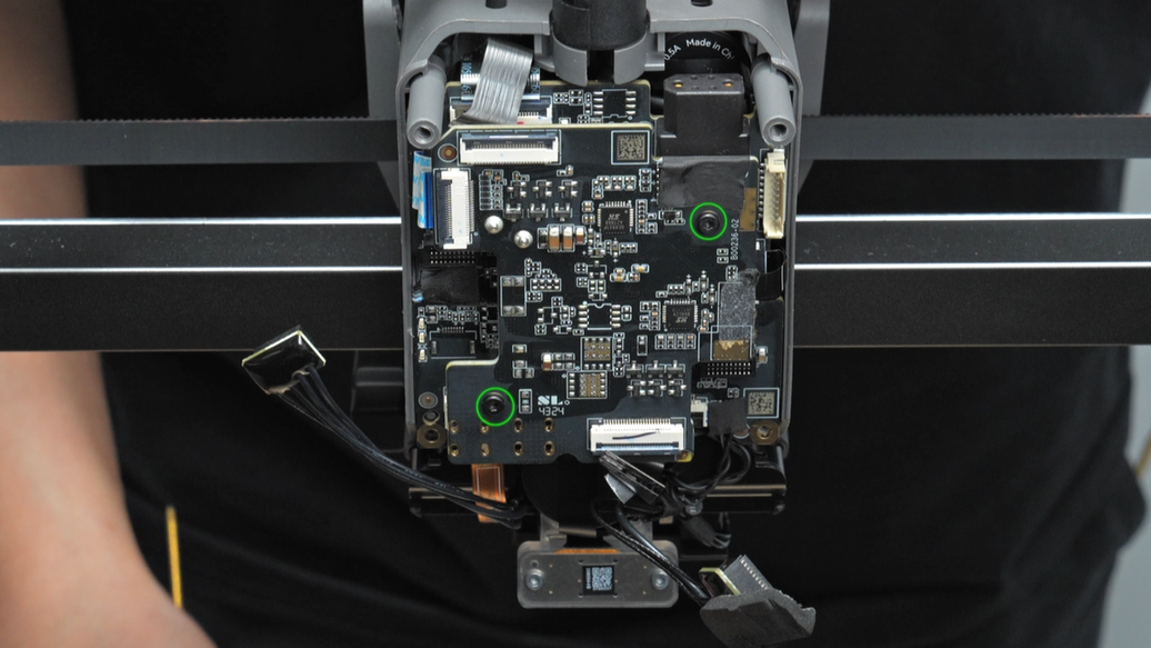
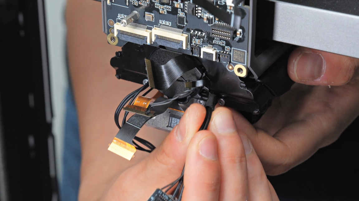
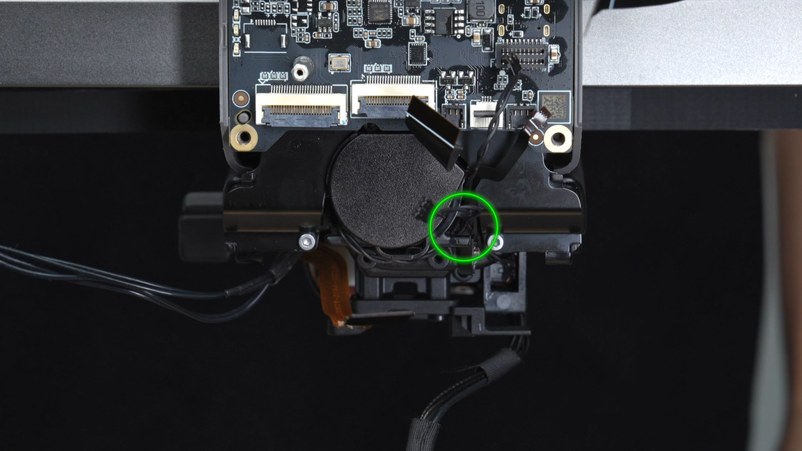
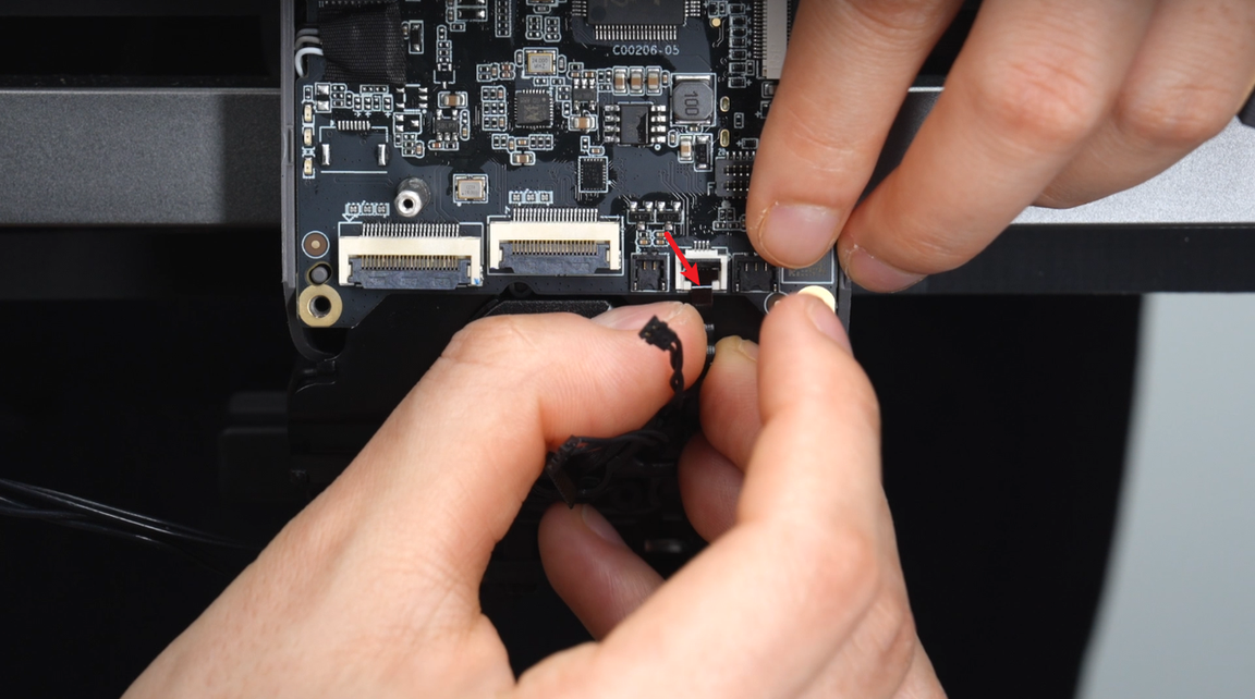
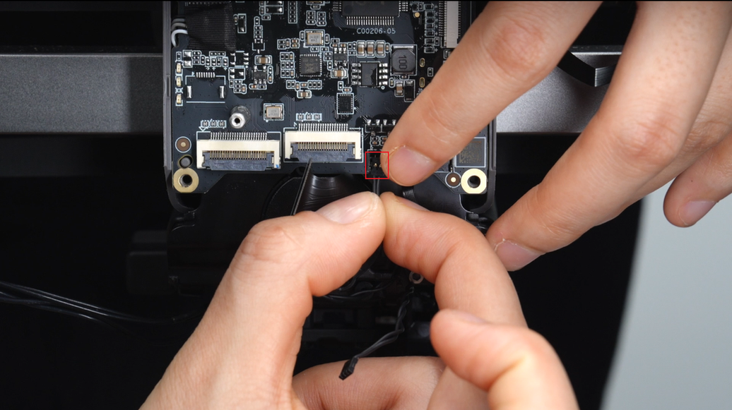
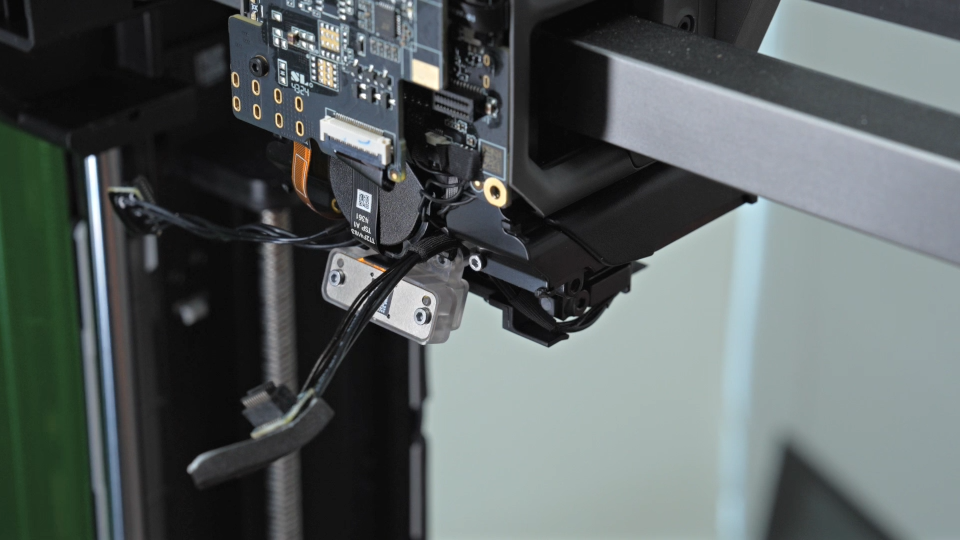
¶ Step 7 - Unplug the plugs of the TH mainboard and remove the nozzle camera
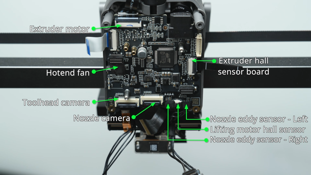
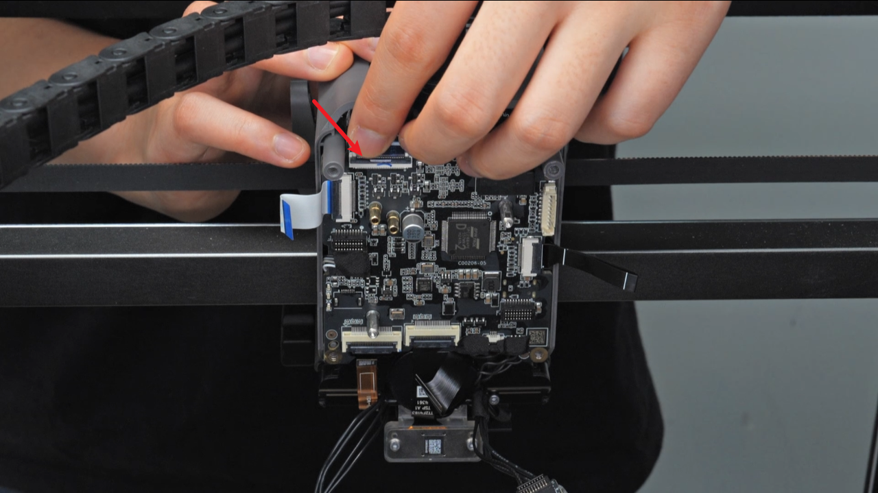
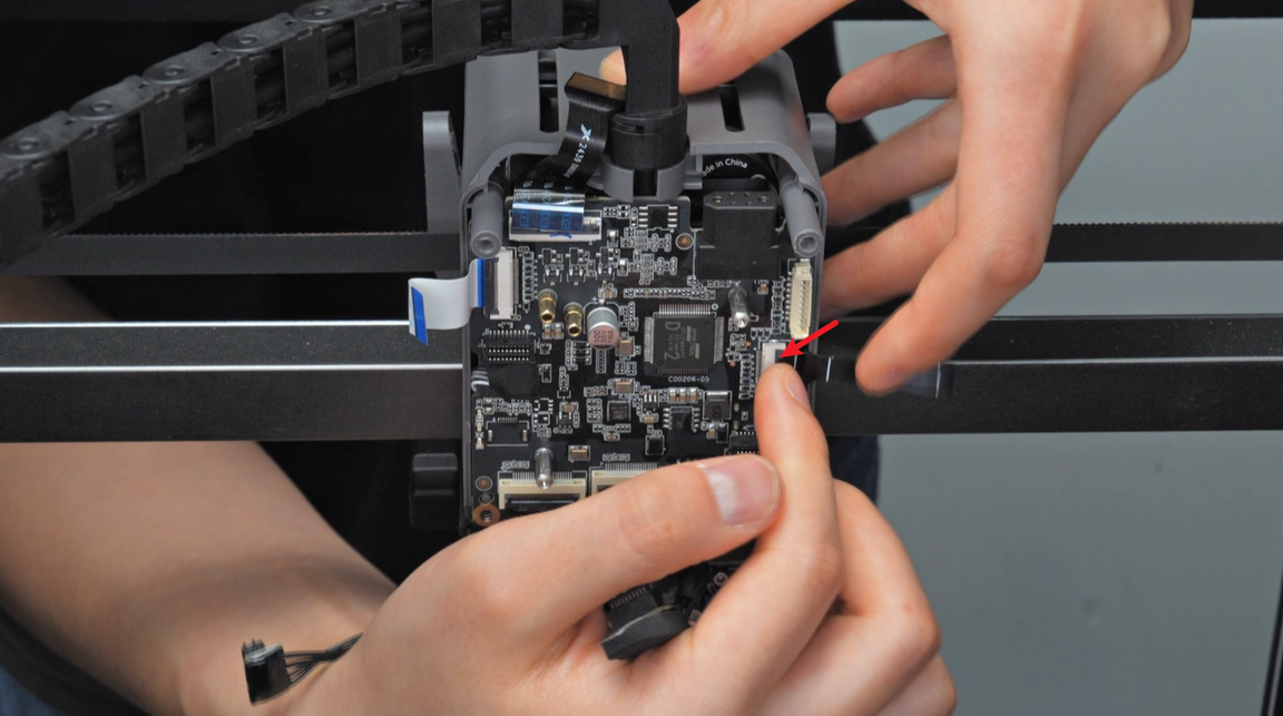
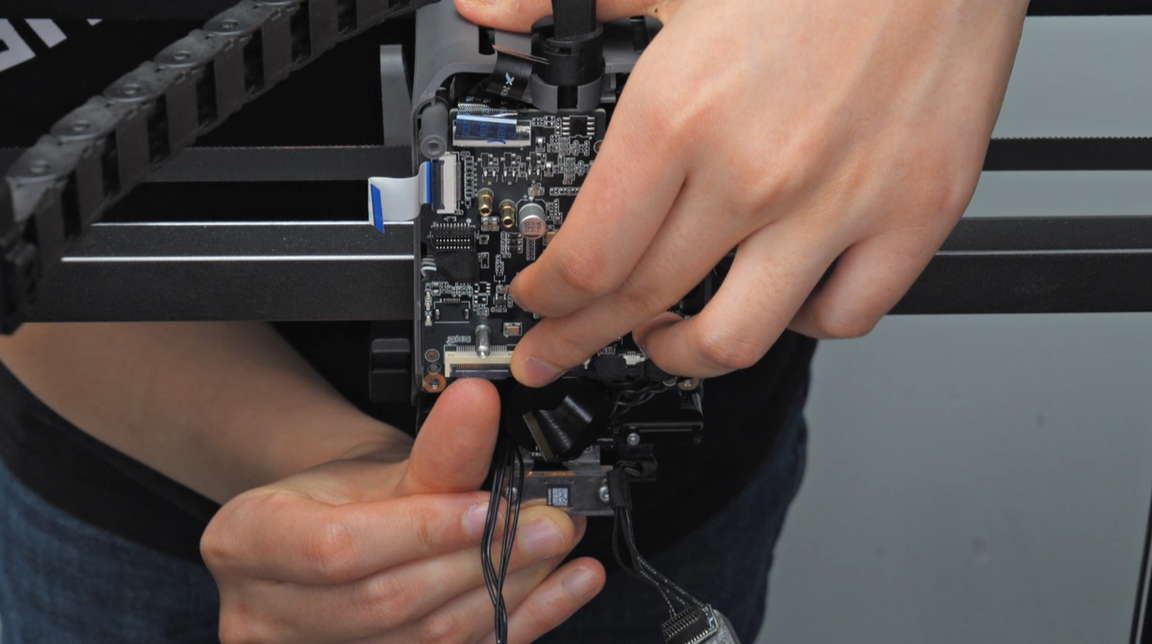
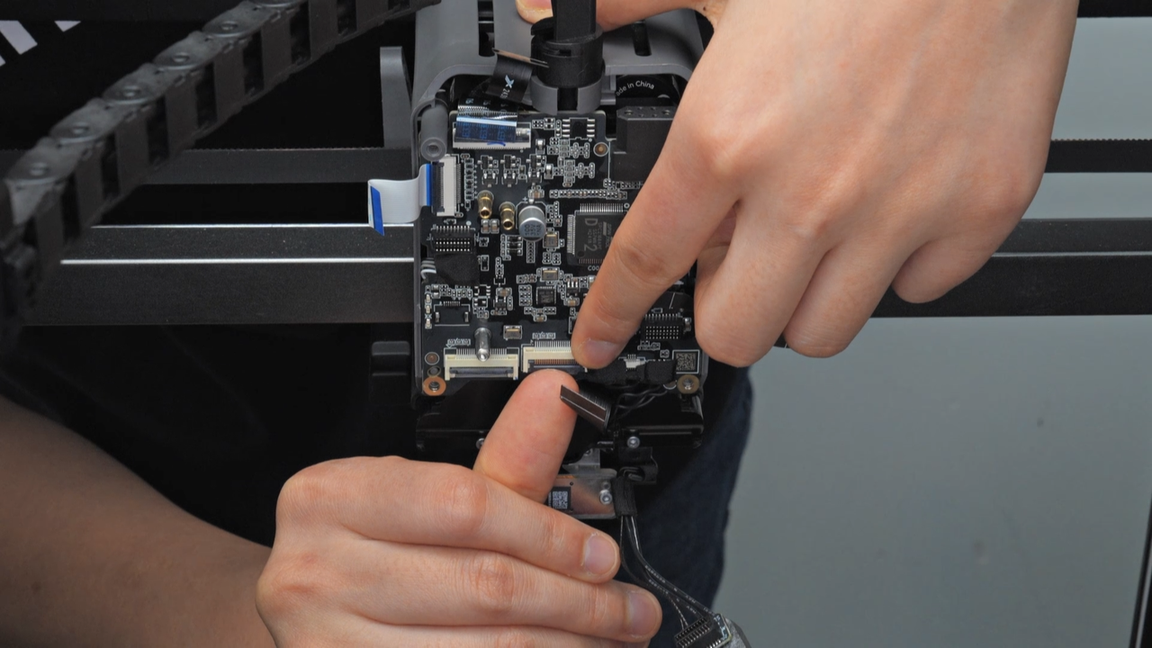
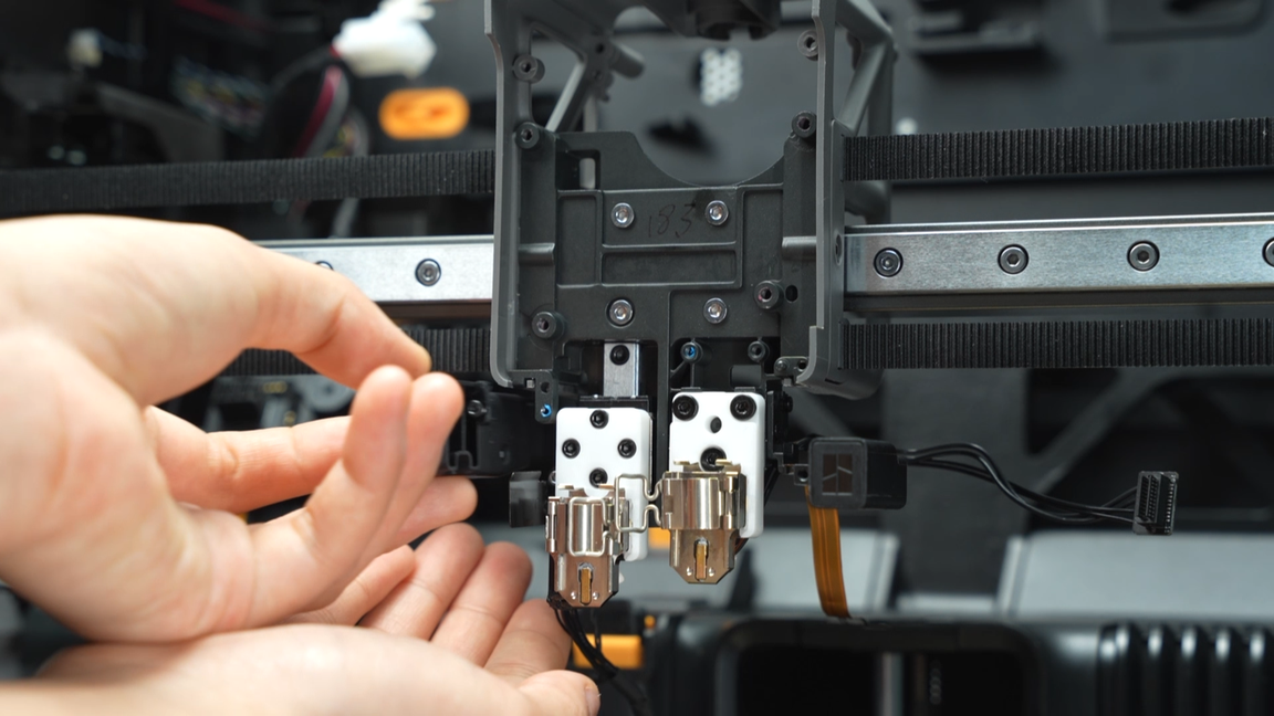
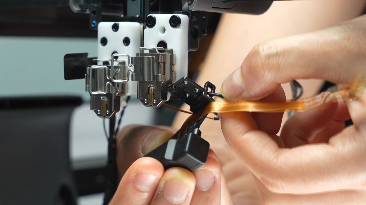
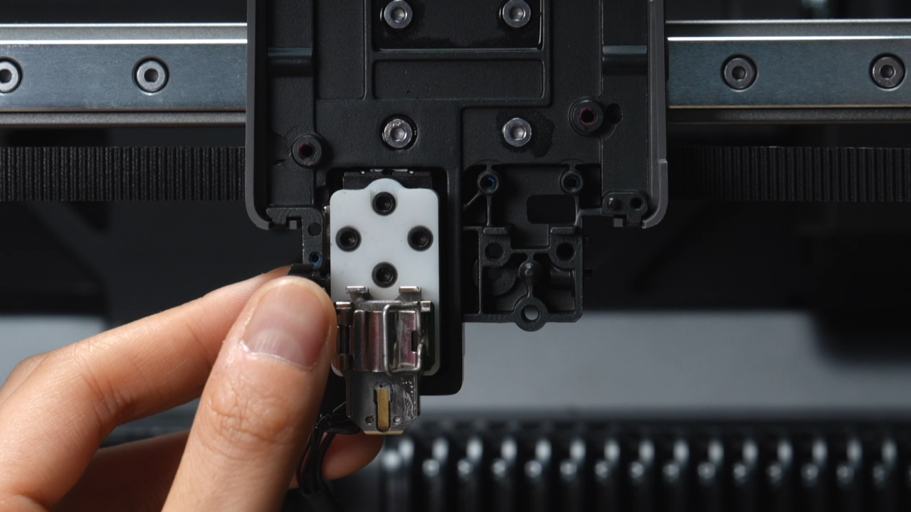
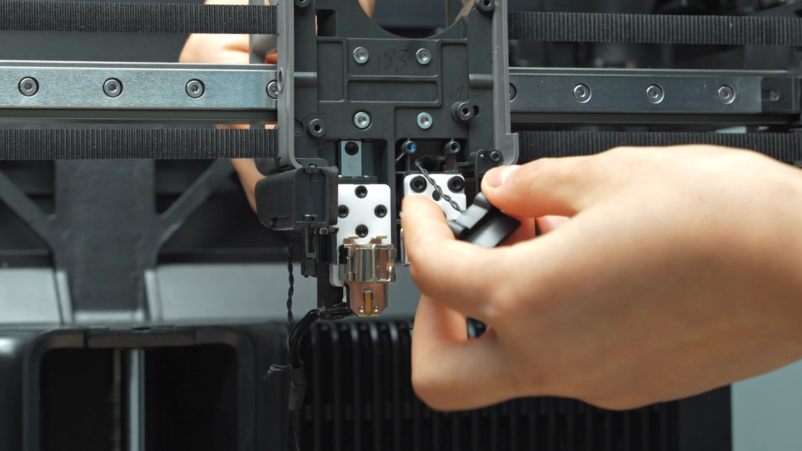
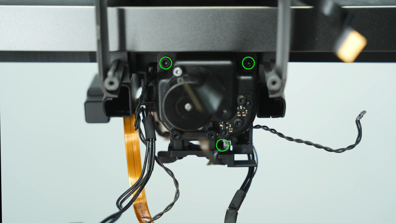
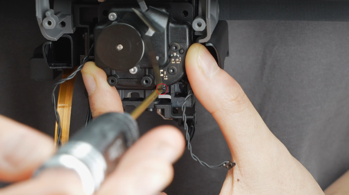
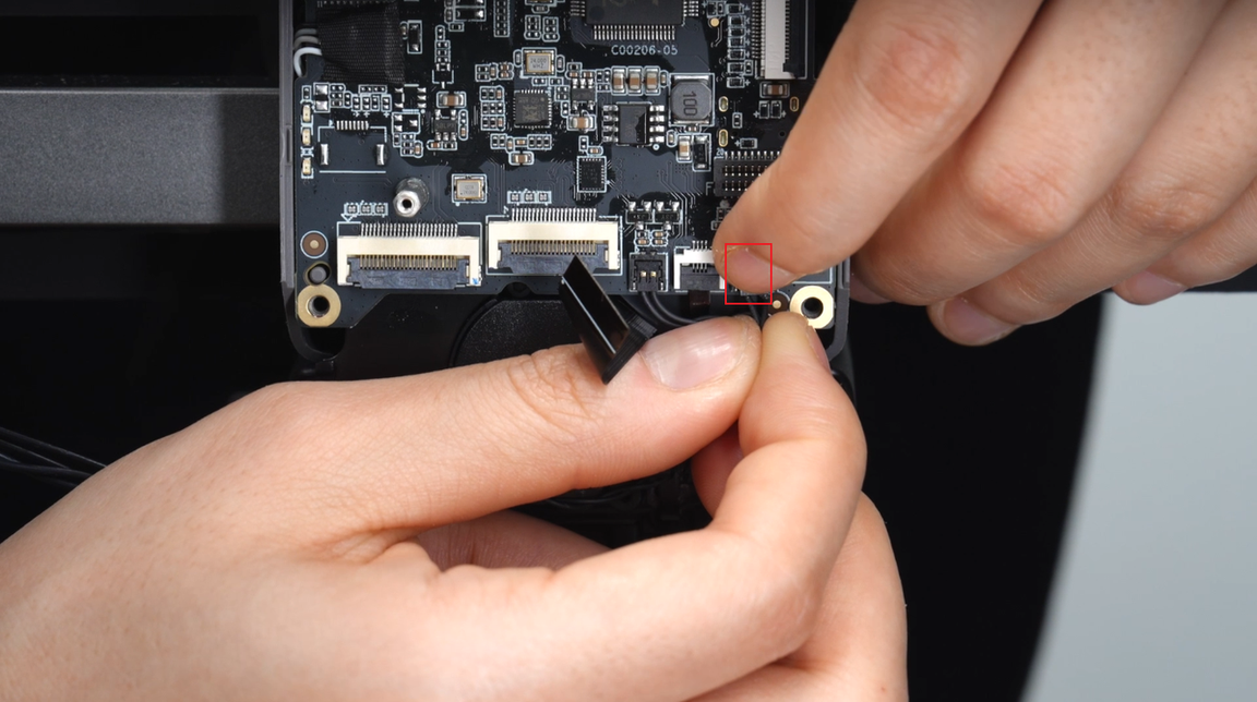
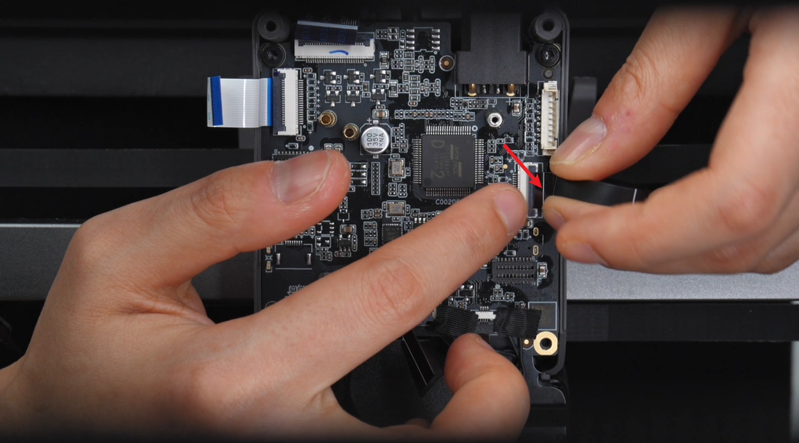
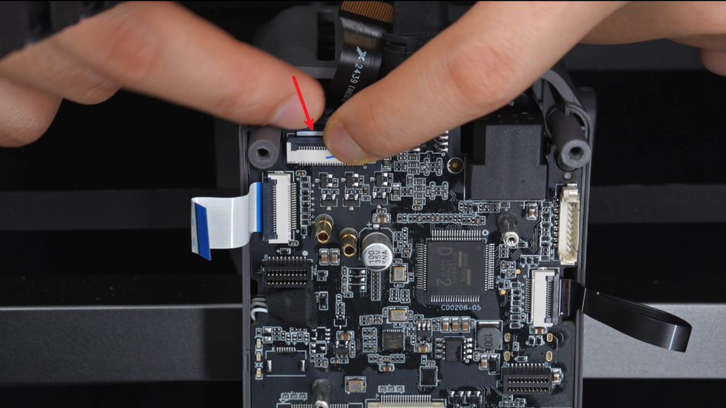
Unplug the extruder servo motor plug, toolhead sensor board plug, toolhead camera plug, nozzle camera plug, left eddy sensor plug, right eddy sensor plug and lifting motor hall plug on the TH mainboard in turn.
 |
 |
 |
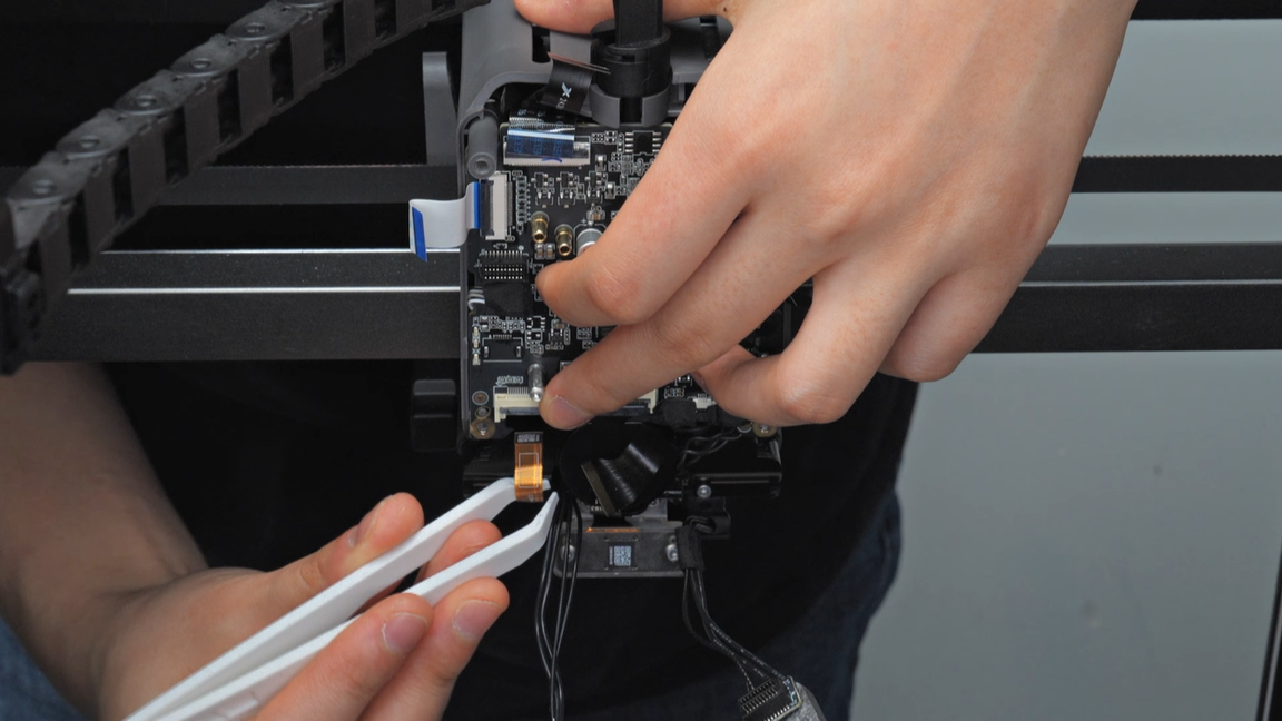
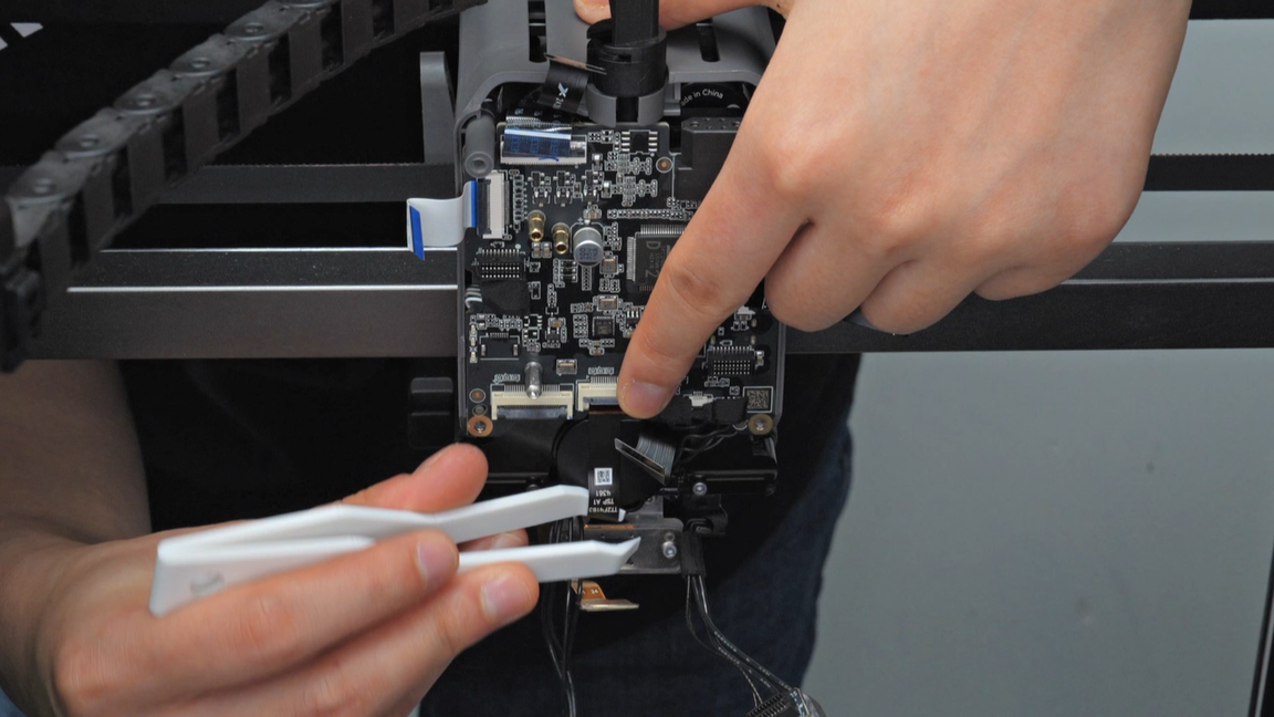
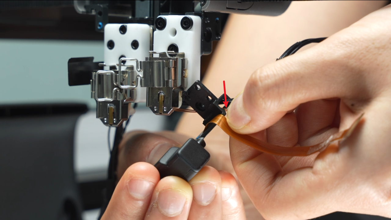
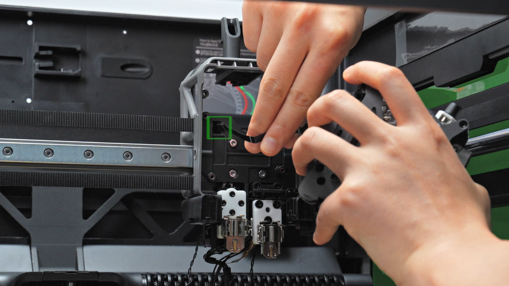
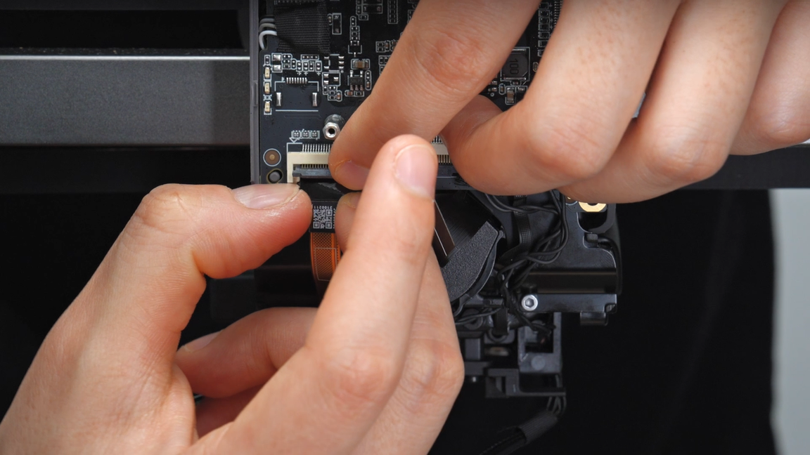
In this step, you need to use a tweezer to peel the back glue of the toolhead camera and nozzle camera FPC cables.
 |
 |
 |
 |
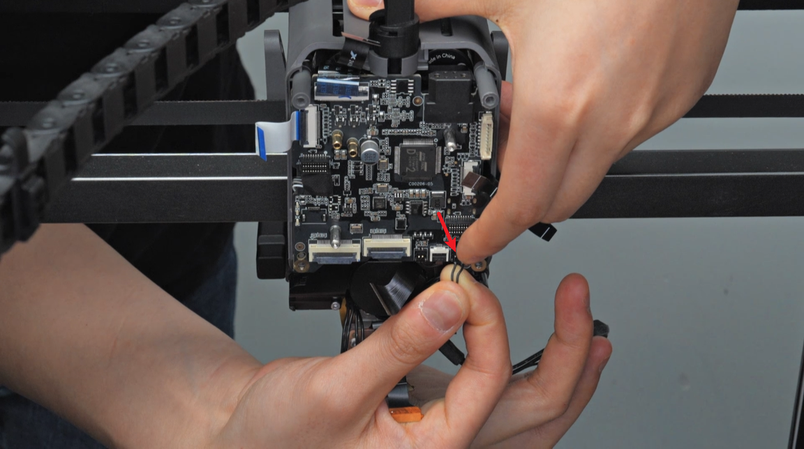
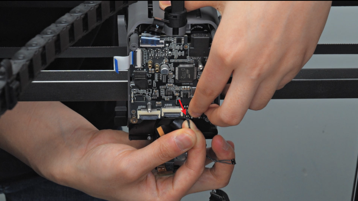
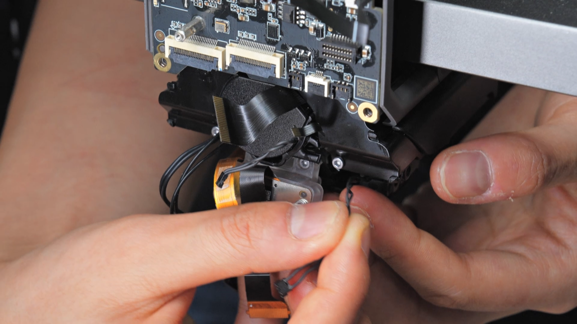
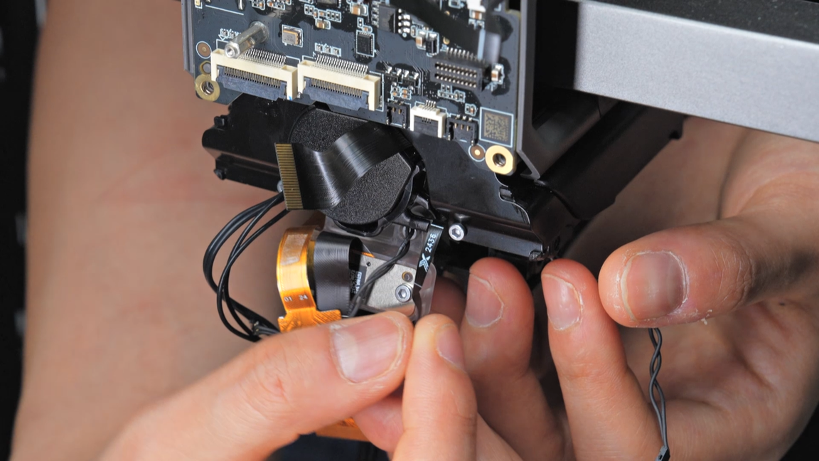
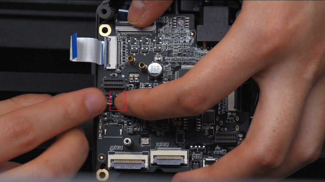
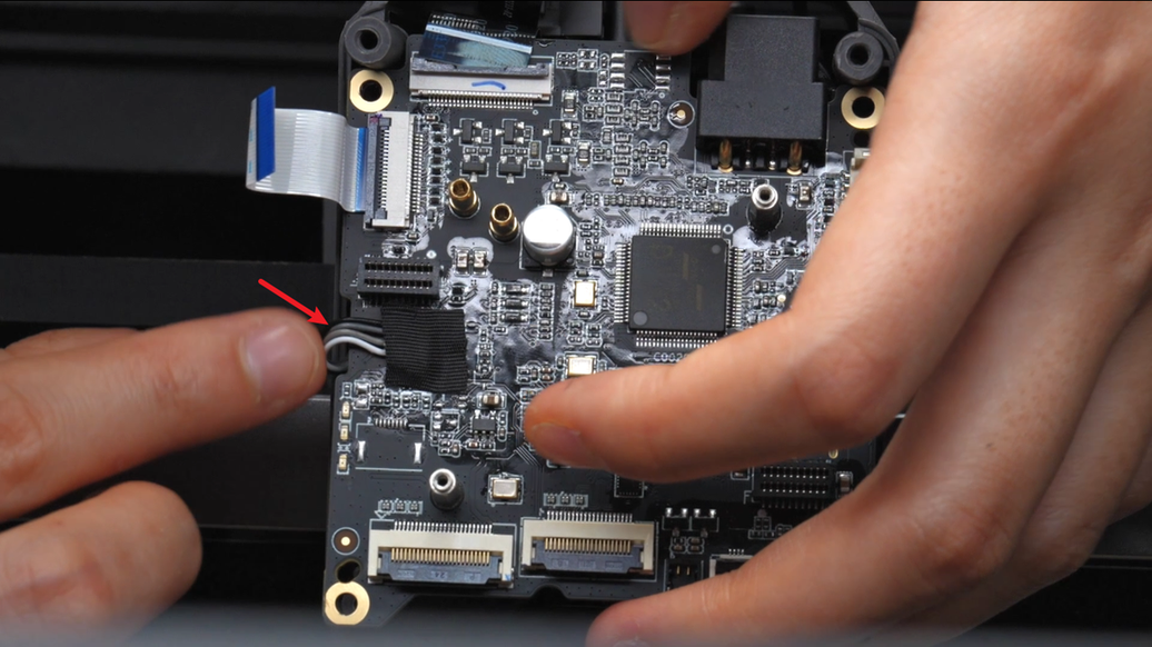
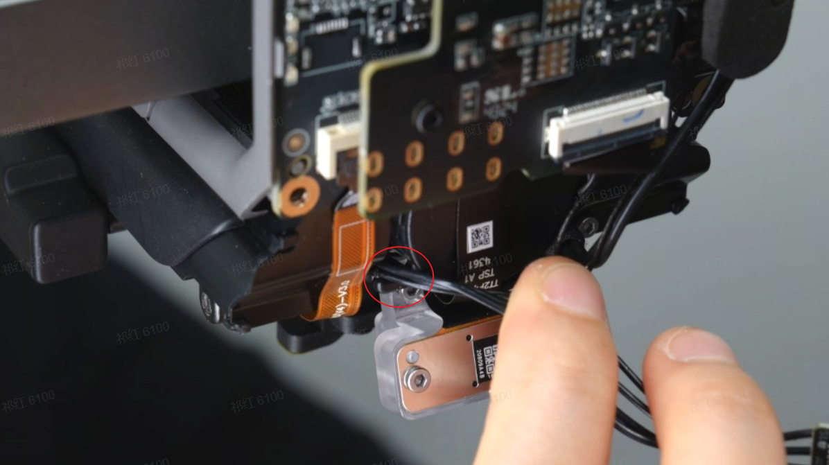
Peel off the tapes from the left eddy sensor and right eddy sensor, unplug the connectors, and finally disconnect the lifting motor hall sensor plug.
 |
 |
 |
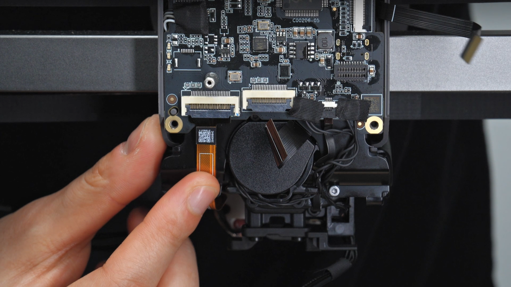
Retrieve the left hotend heating assembly cable, the left eddy sensor plug, the right eddy sensor plug, and the lifting motor hall cable from the two cable management slots below.
 |
 |
 |
 |
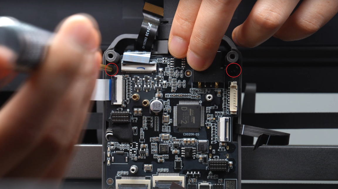
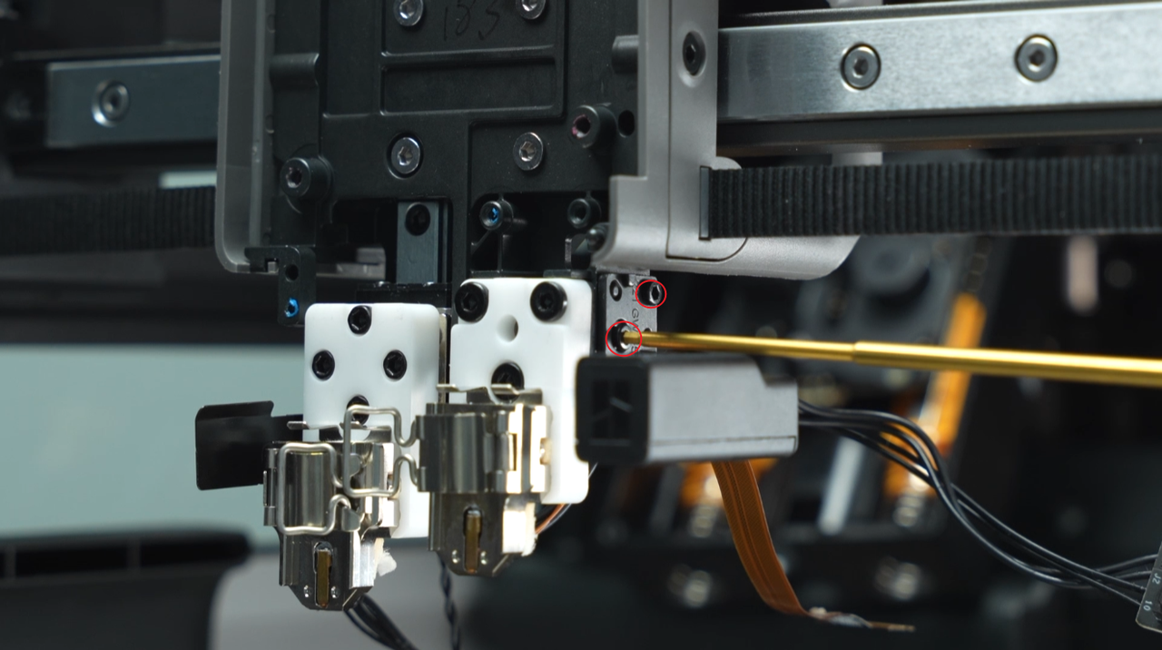
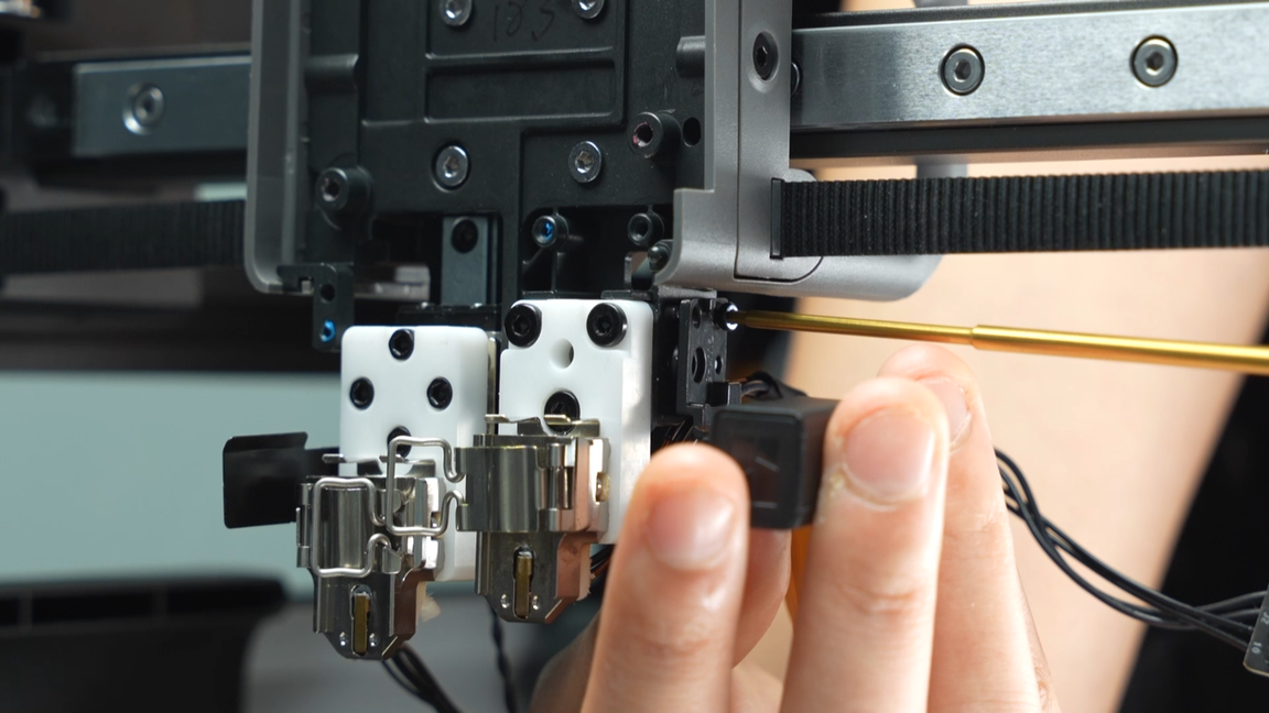
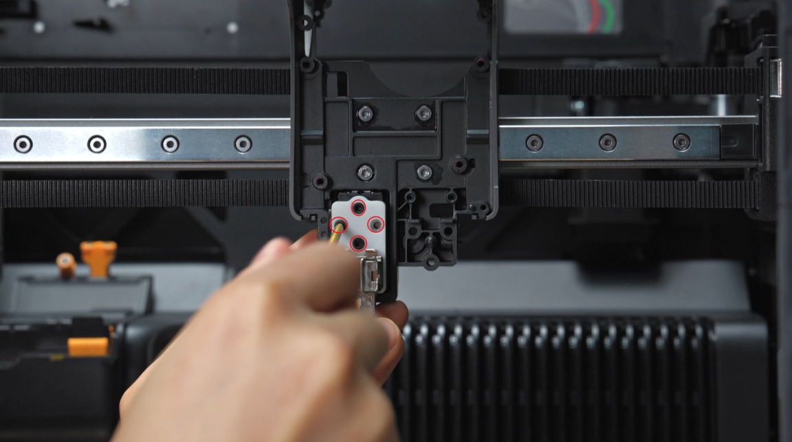
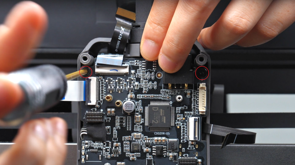
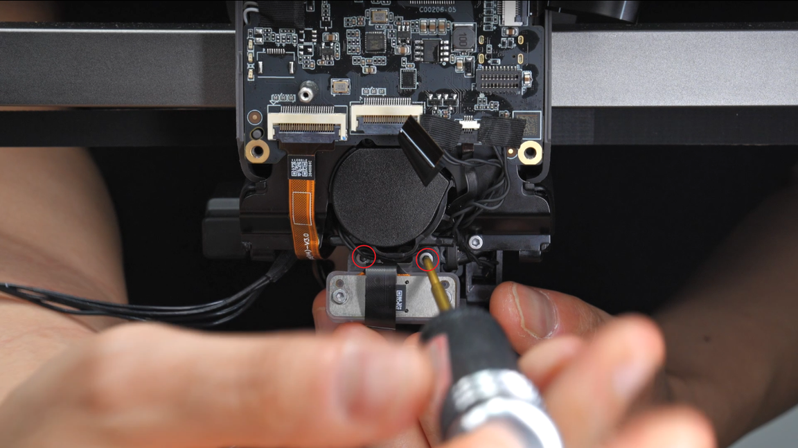
Unscrew the two fixing screws of the nozzle camera, and remove the nozzle camera.
 |
 |
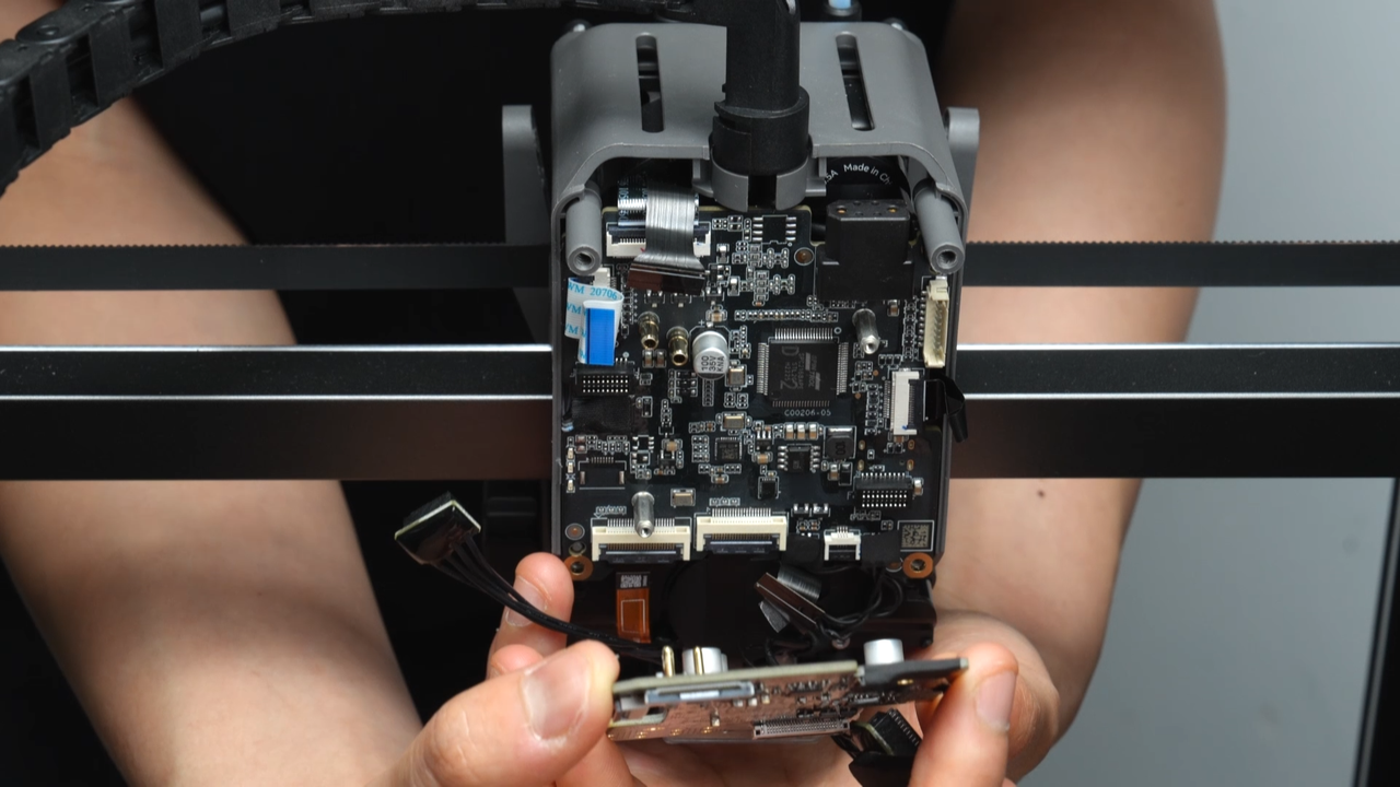
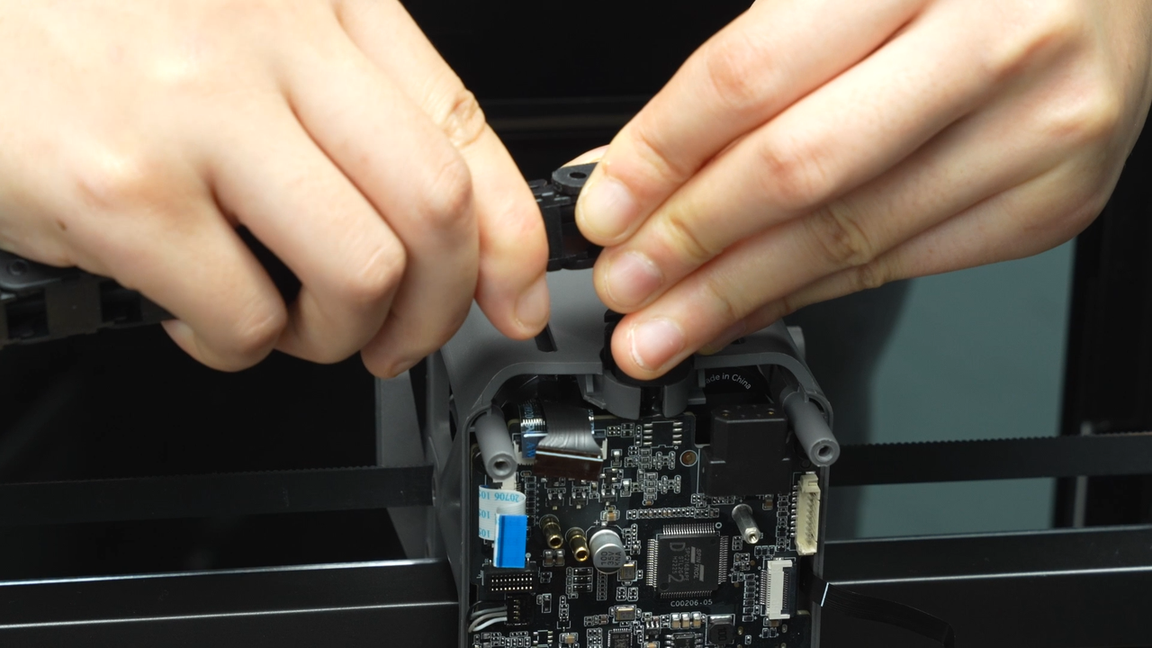
Unscrew the remaining two fixing screws of the TH board, gently lift the TH board from below to create space for removing the hotend fan, pull out the hotend fan cable, and unplug the hotend fan connector.
 |
 |
 |
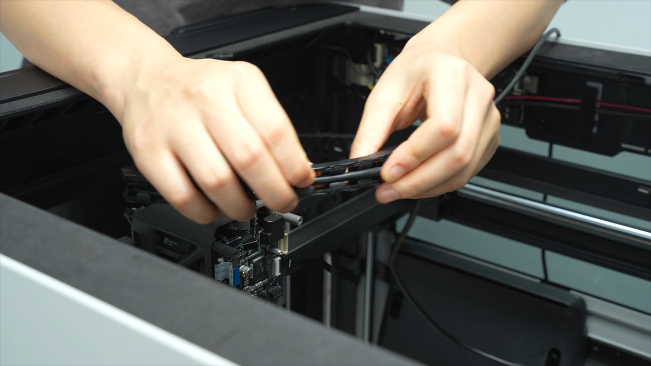
Remove the section of the cable chain closest to the cable chain bracket on the toolhead and pull out approximately four sections of cable from the cable chain.
 |
 |
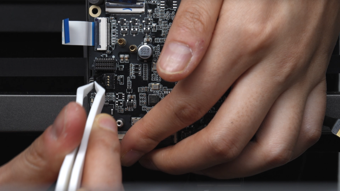
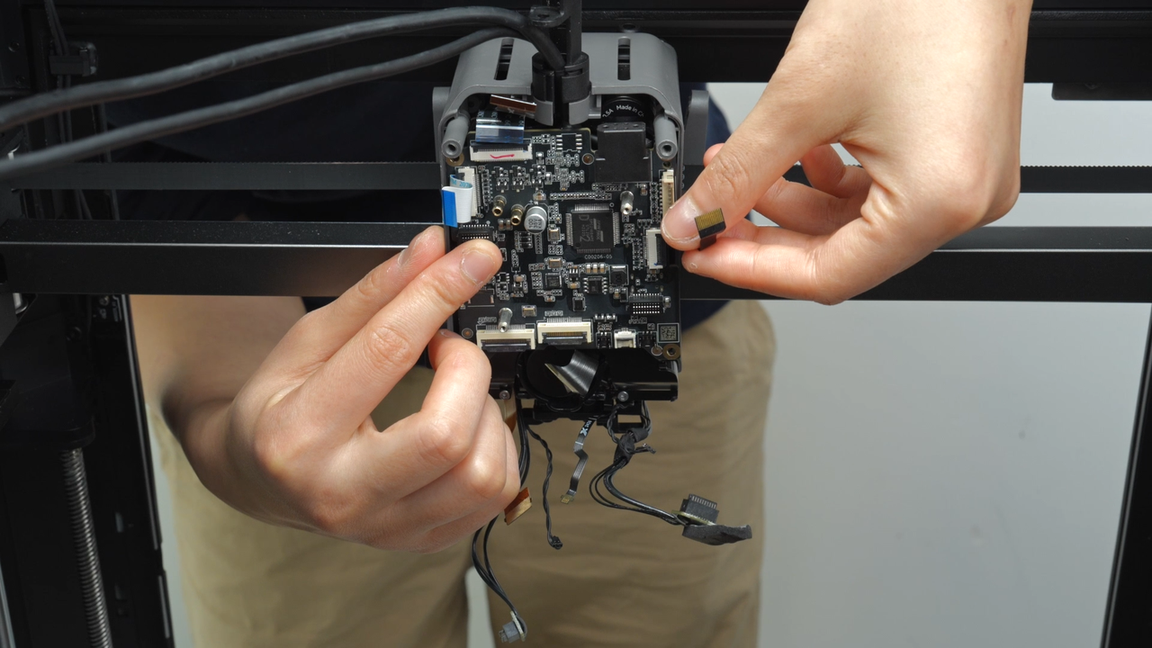
Push the TH board downward to create a longer length of cable, making it easier to pull out the two cables from the TH board. When pulling out the cables, you can do so by pulling them upward from below.
 |
 |
 |
 |
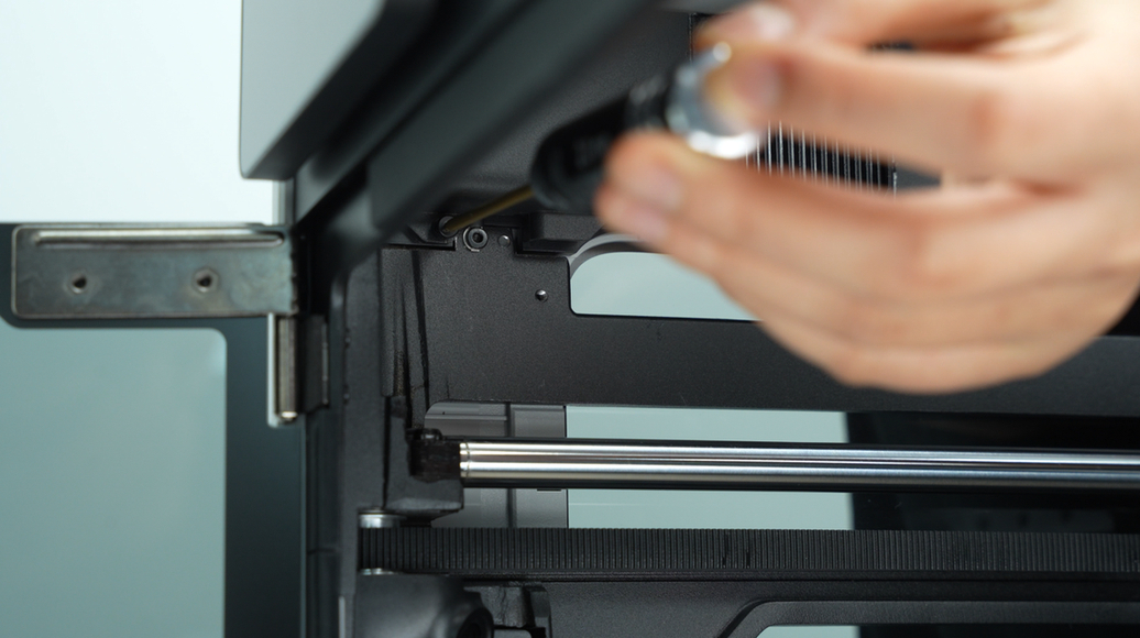
¶ Step 8 - Remove the AP board cover,buffer and disconnect the USB-C cable and the MC-TH cable
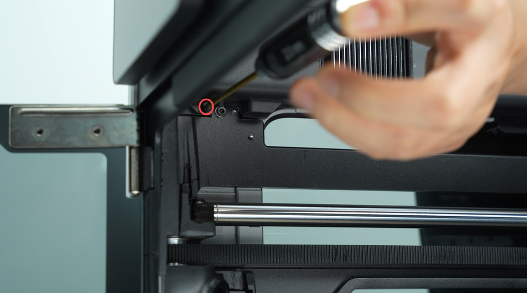
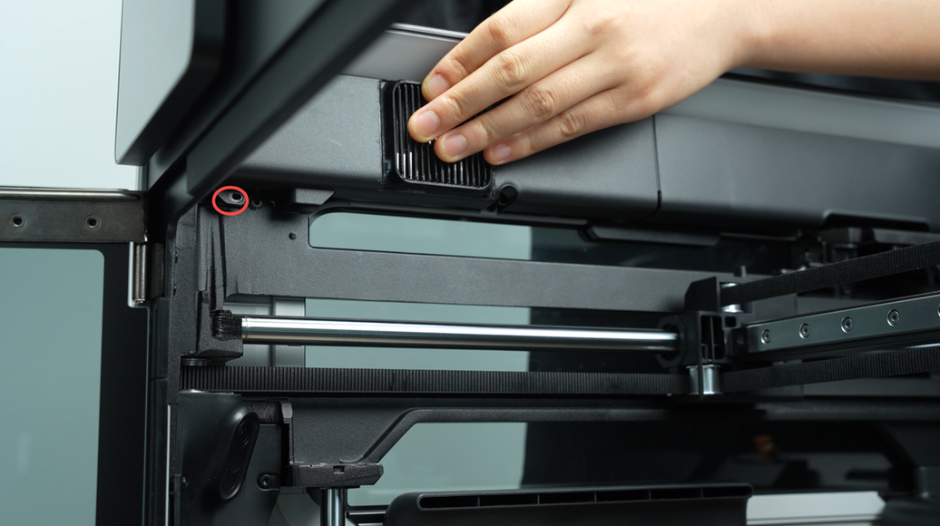
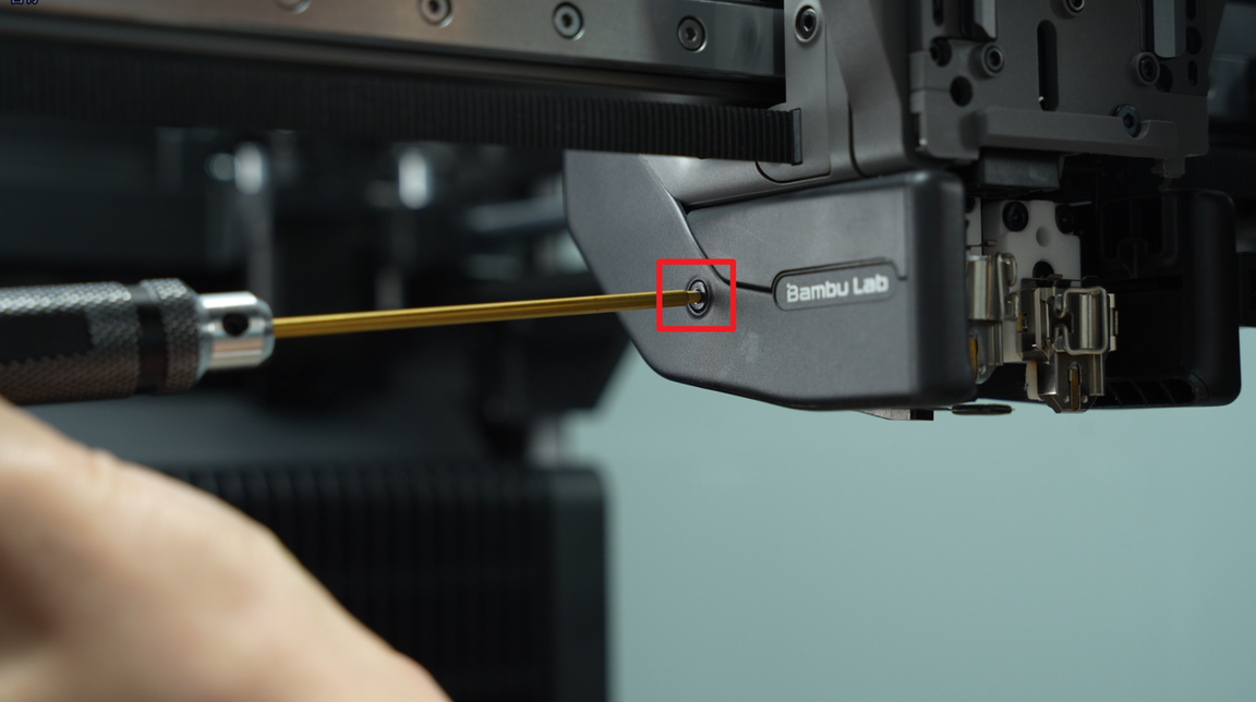
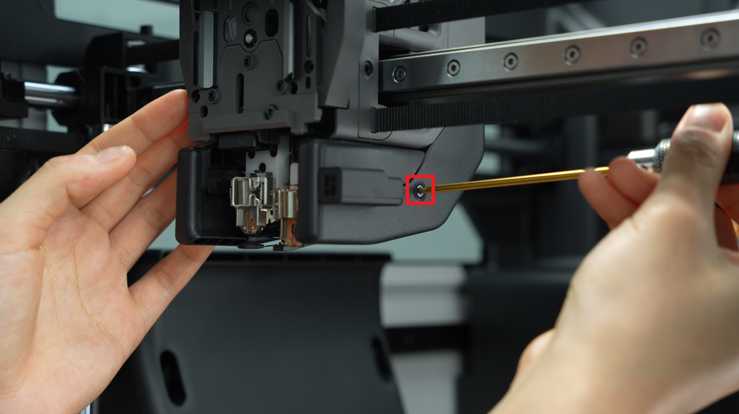
Unscrew one screw from the AP board cover and remove the AP board cover.
 |
 |
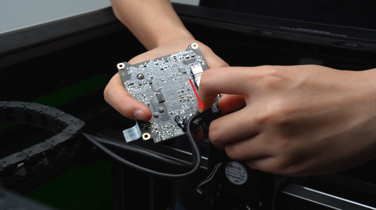
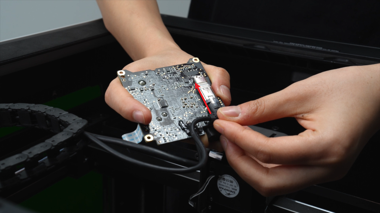
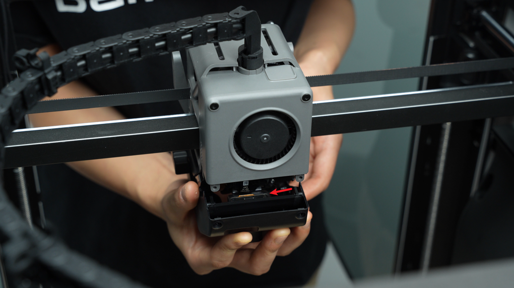
Disconnect the USB plug from the AP board and pull out the USB-C cable from the cable management slot.
 |
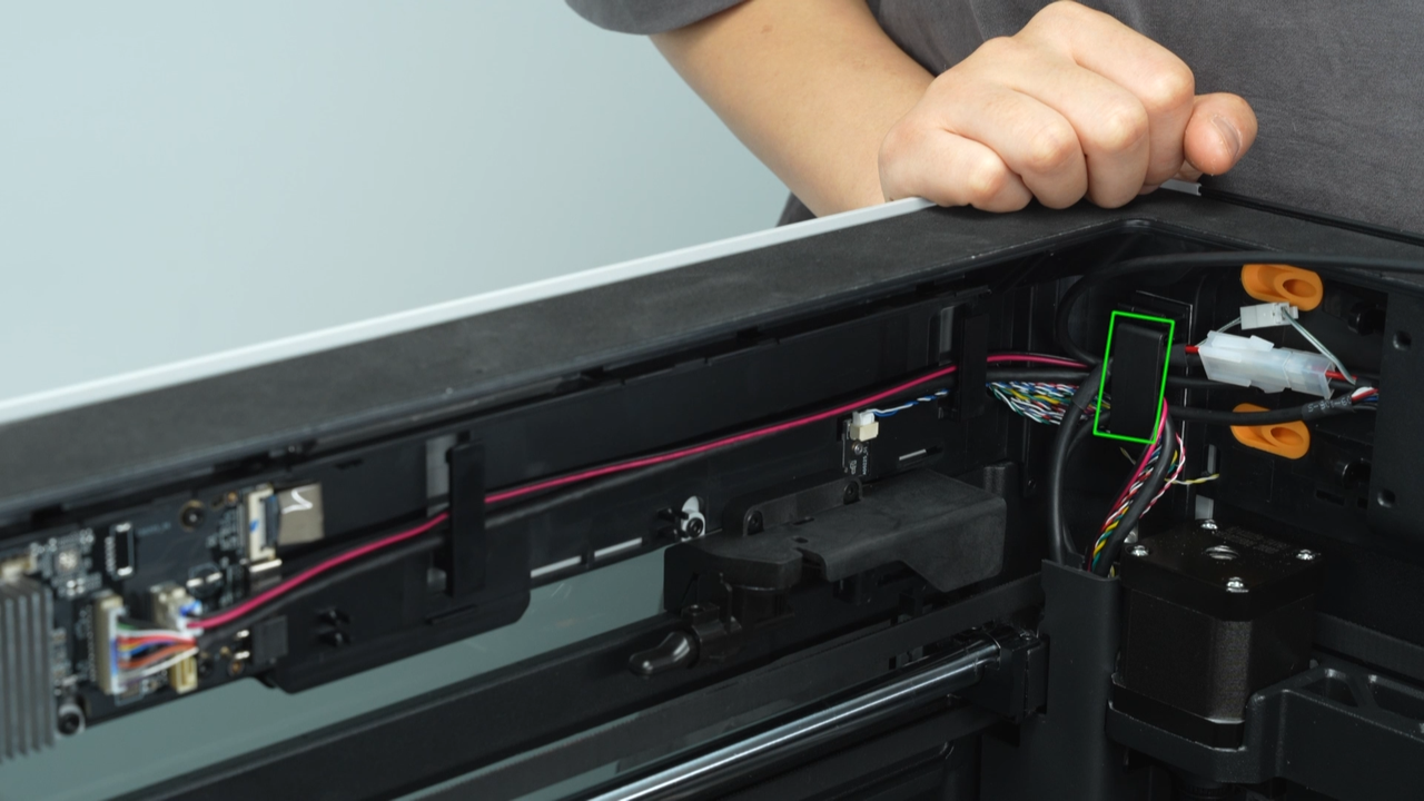 |
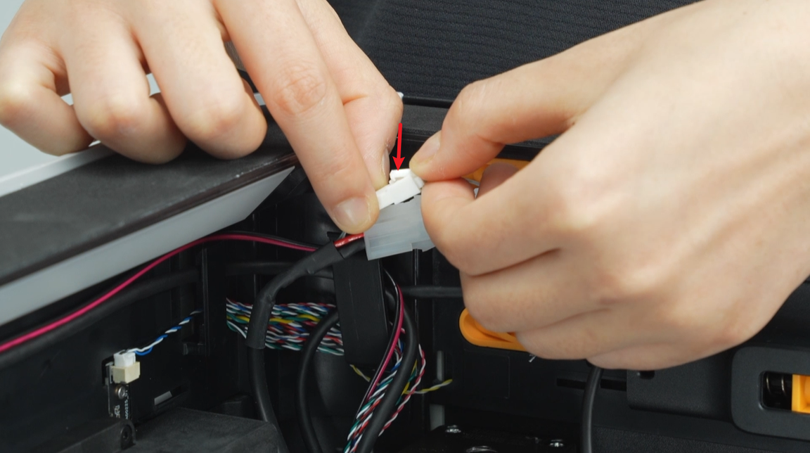
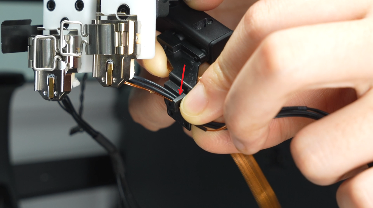
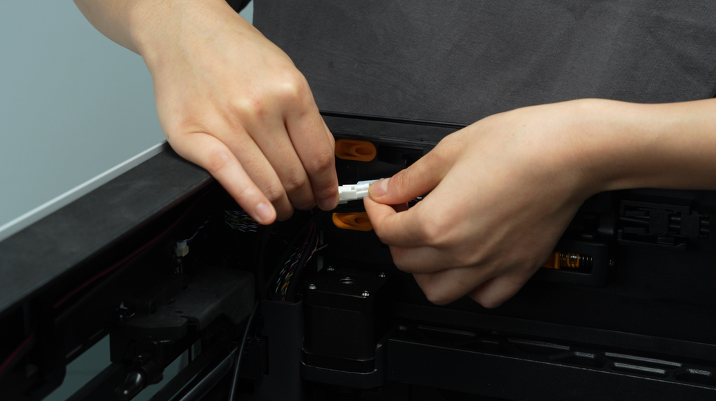
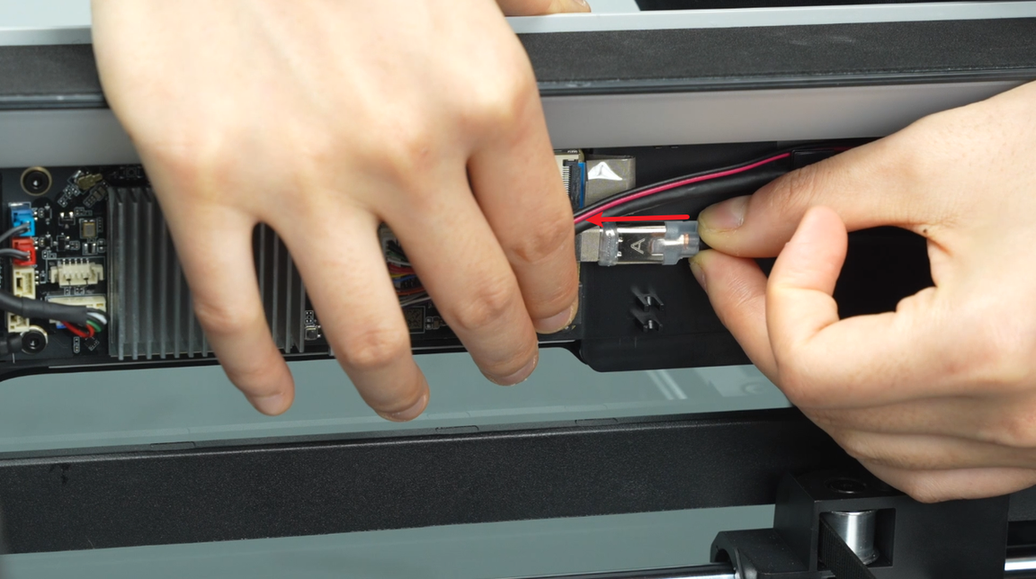
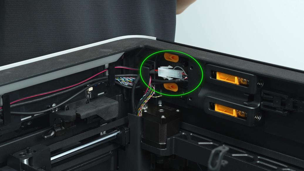
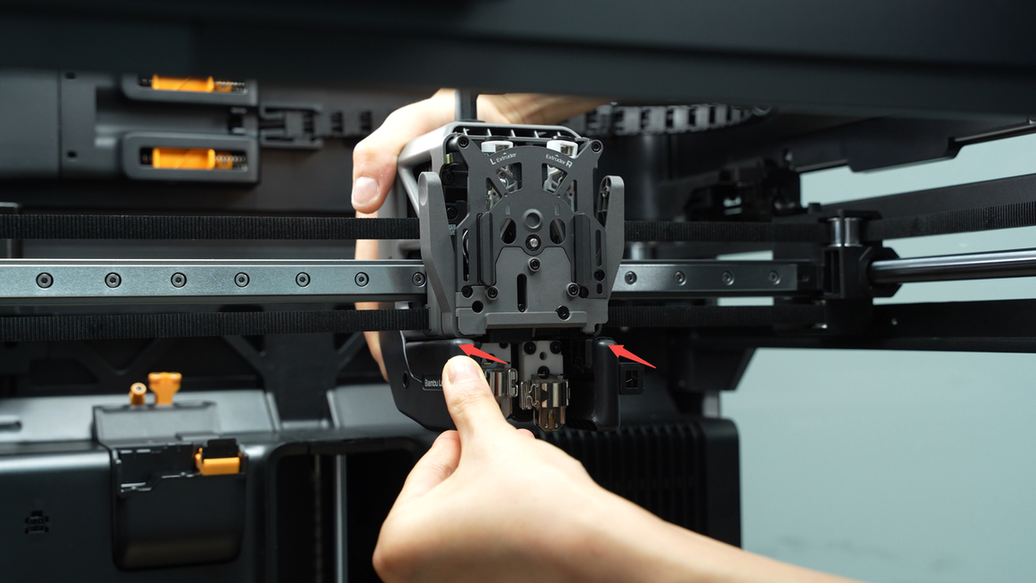
The MC-TH cable has two connectors, one is the communication connector, and the other is the power conversion connector. Press the latch to unlock and disconnect the two connectors of the MC-TH cable.
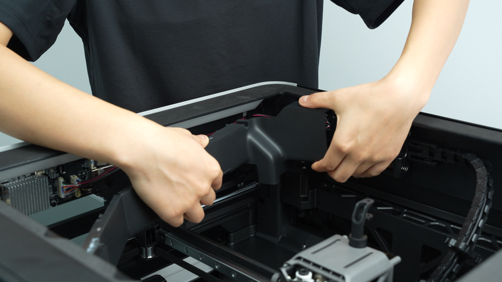
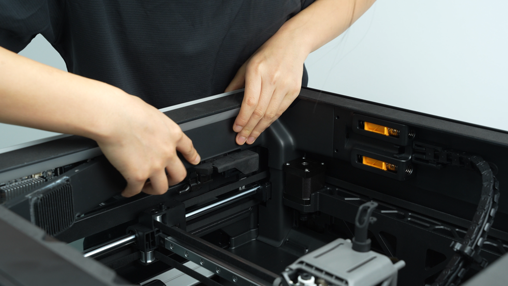
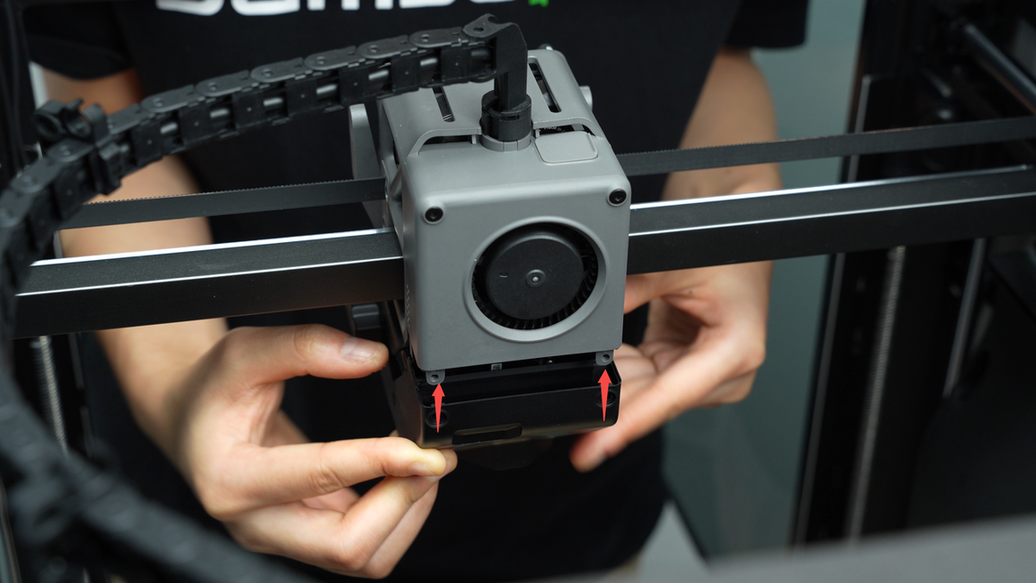
Unscrew the four screws of the buffer, loosen the buffer, revealing the USB-C cable and MC-TH cable inside.
 |
 |
 |
 |
¶ Step 9 - Disconnect the TH board, USB-C cable and cable chain.
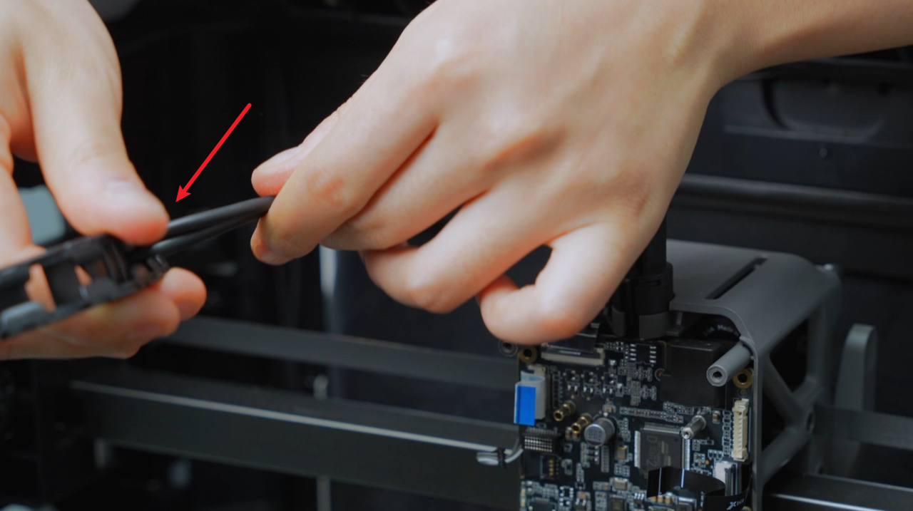
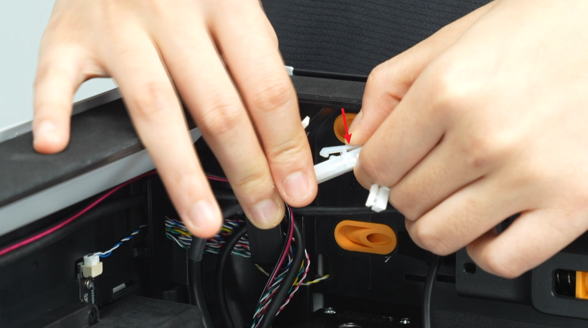
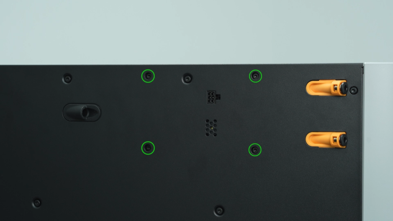
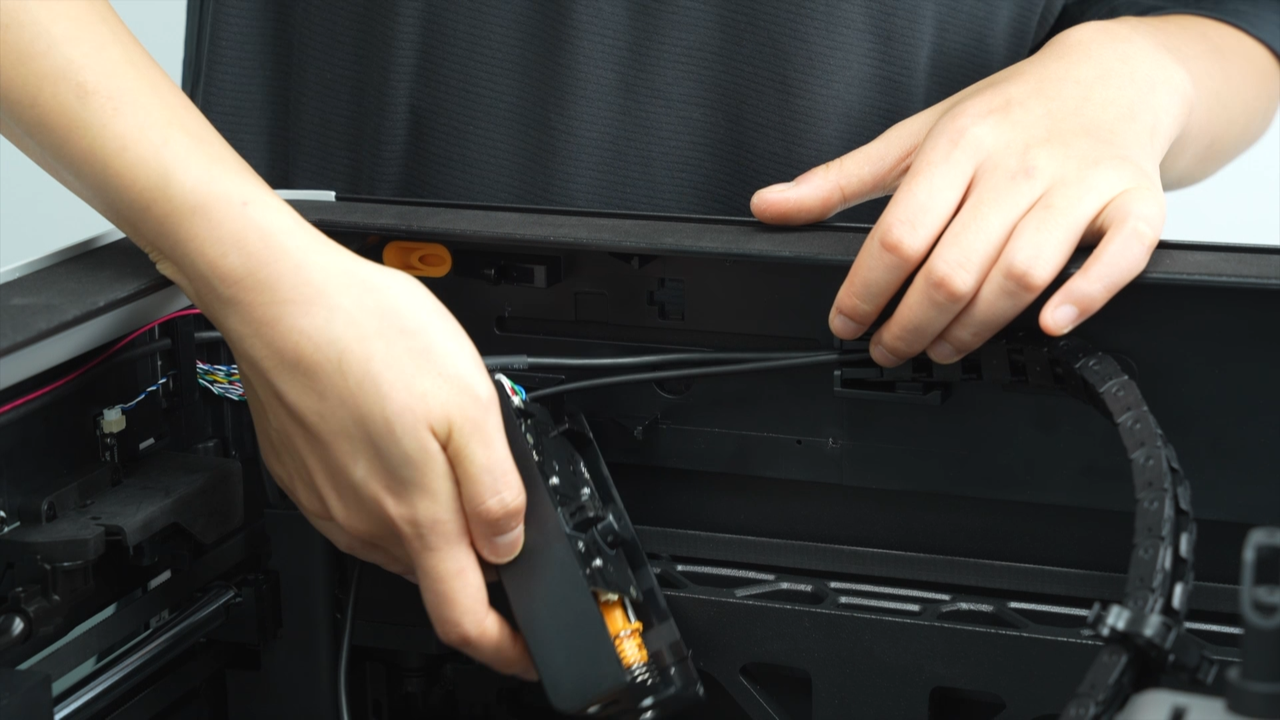
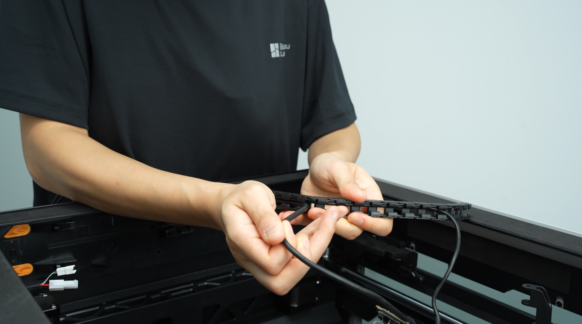
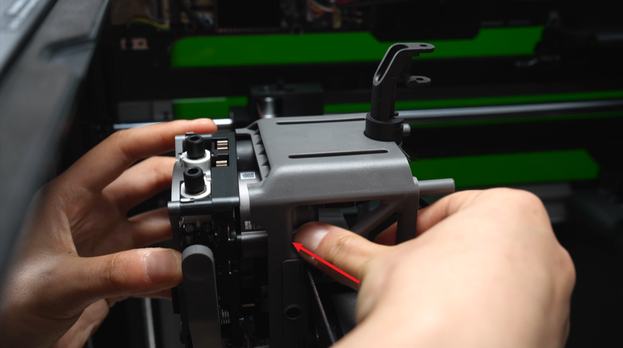
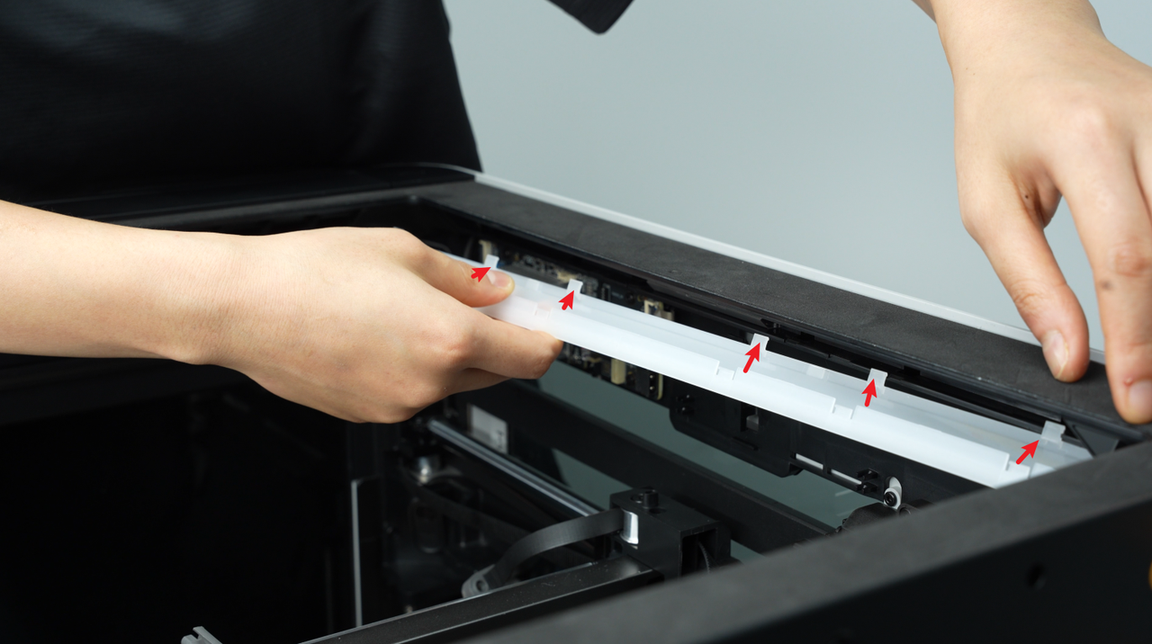
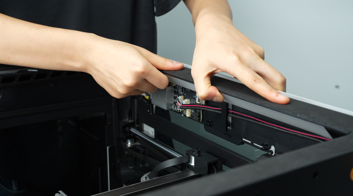
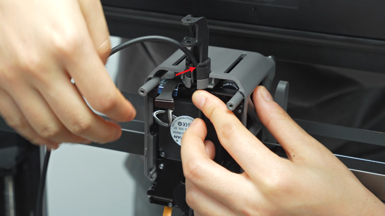
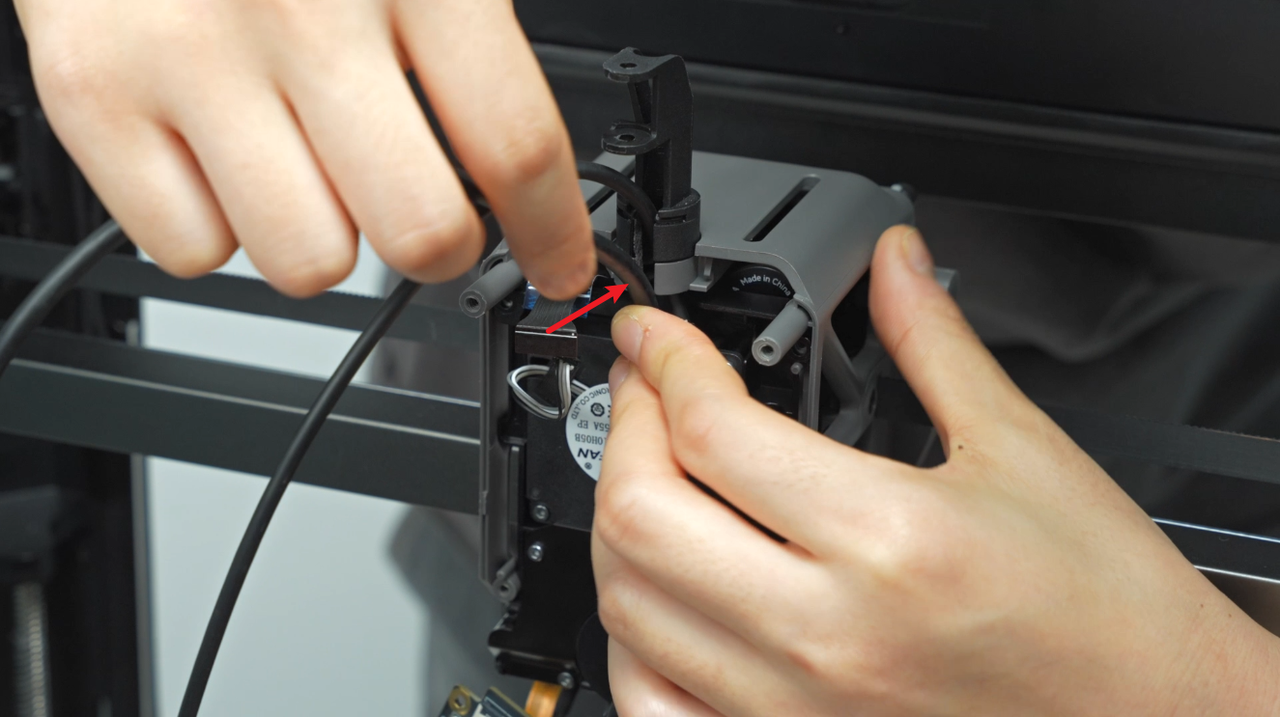
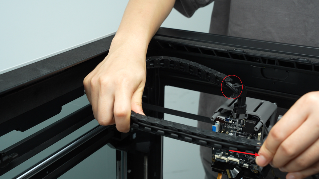
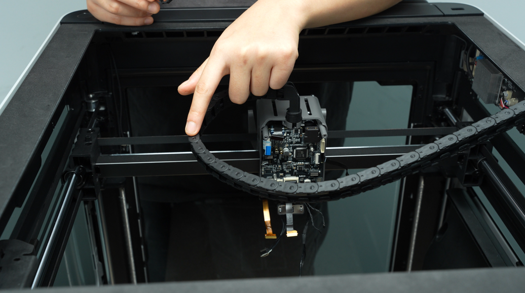
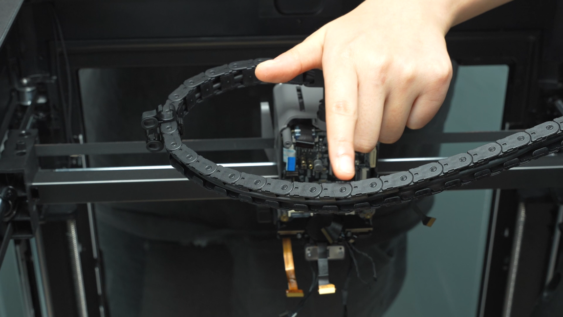
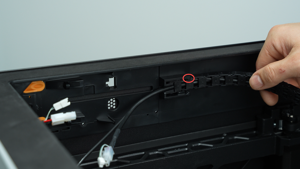
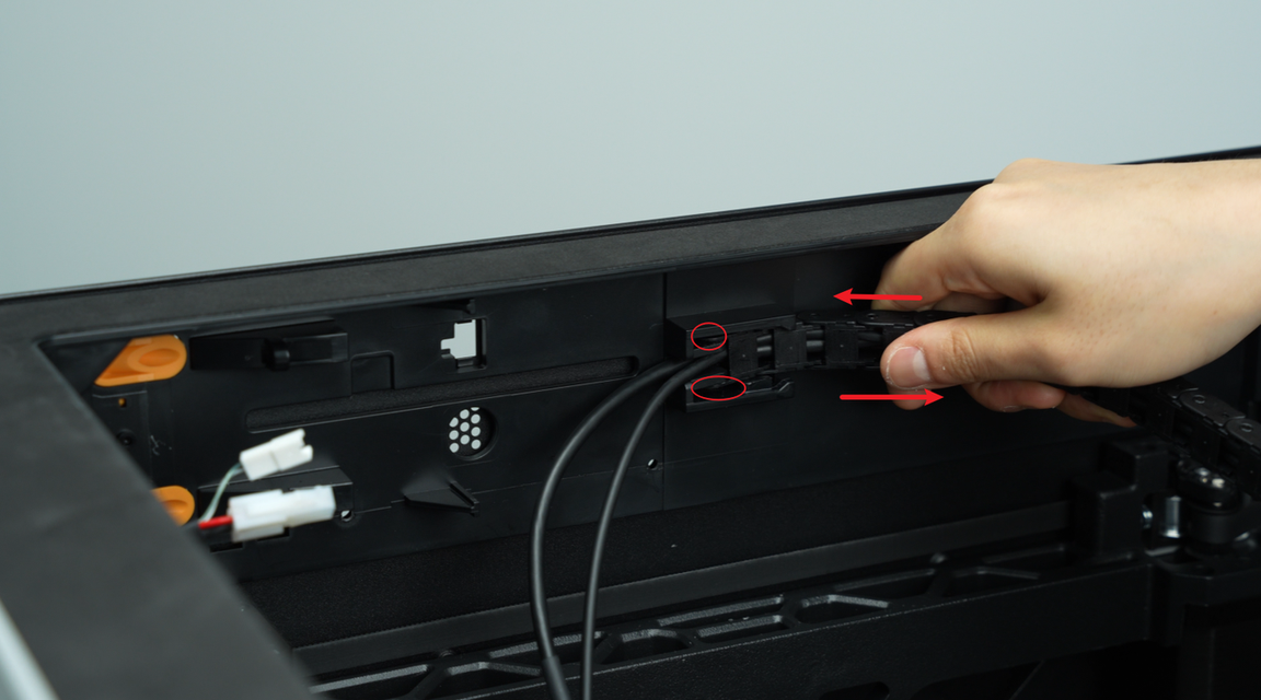
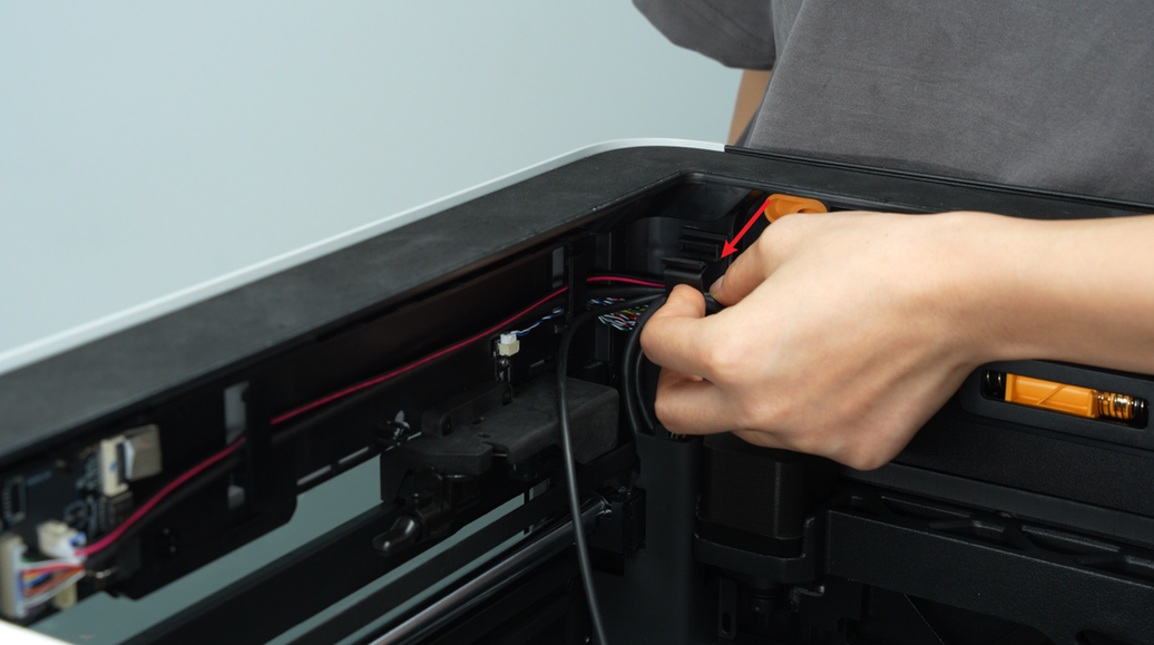
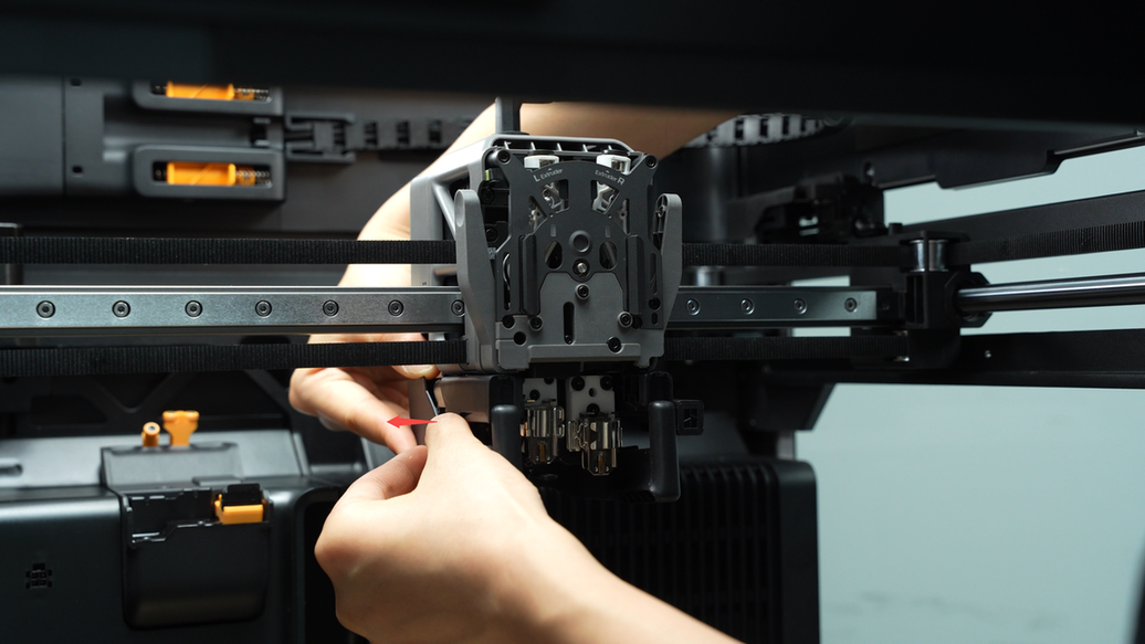
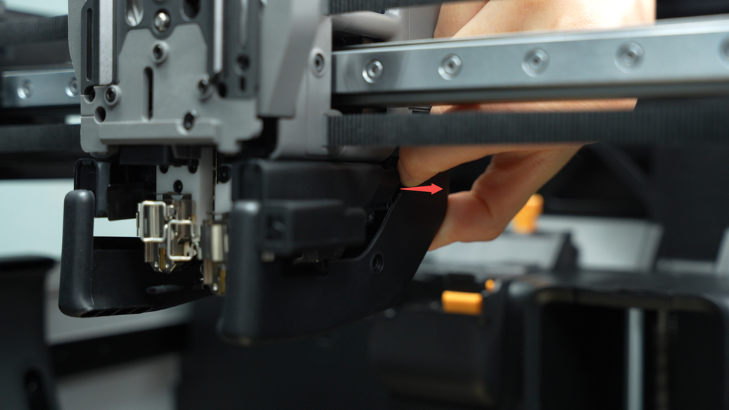
Disconnect the cable chain from the upper cover frame, follow the arrows to first remove the top half of the cable chain, and then pull out the cable chain completely.
 |
 |
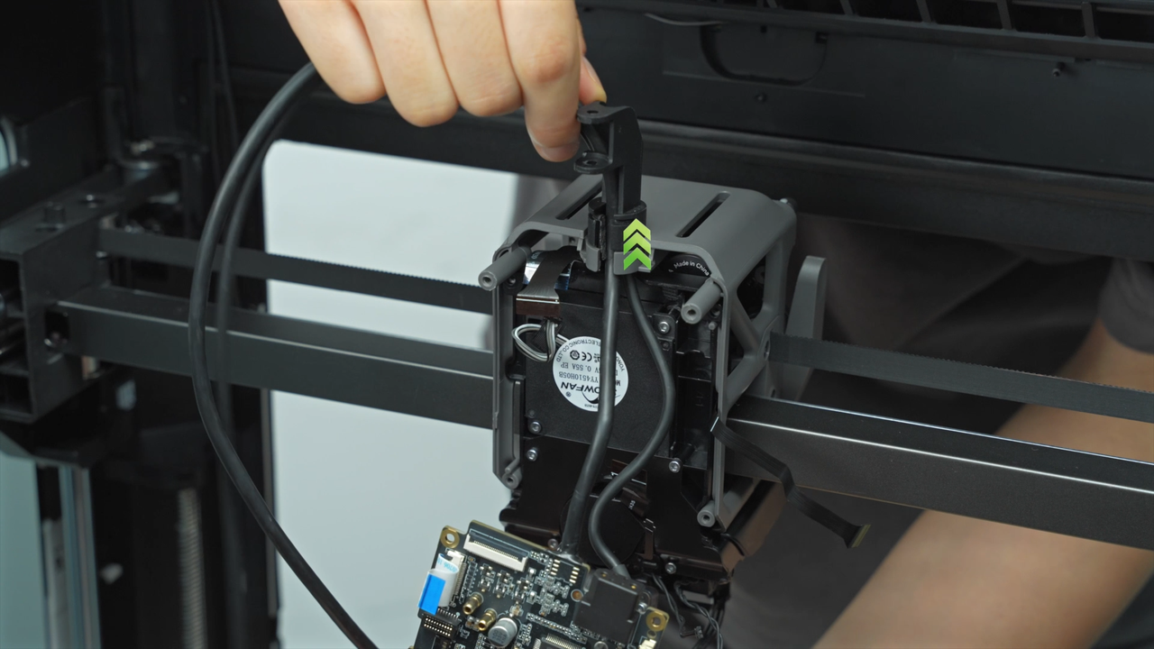
Loosen and remove the two tube organizers on the cable chain, and pull out the USB-C cable and the MC-TH cable from the cable chain.
 |
 |
 |
 |
 |
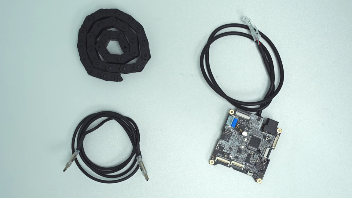
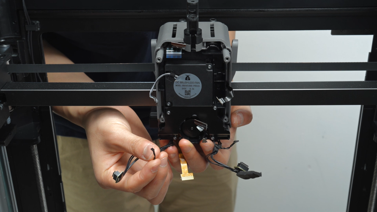
Upon completing this step, you will have the USB-C cable, TH board, and cable chain separately.
¶ Step 10 - Remove the hotend fan
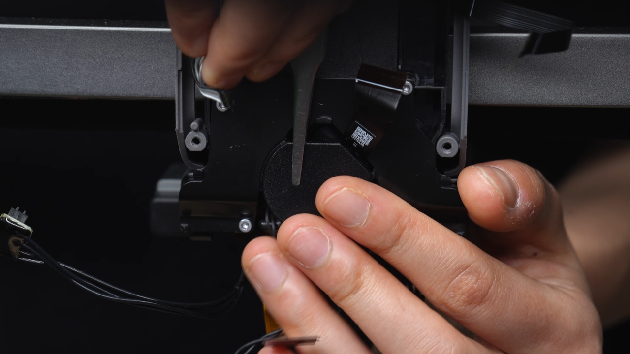
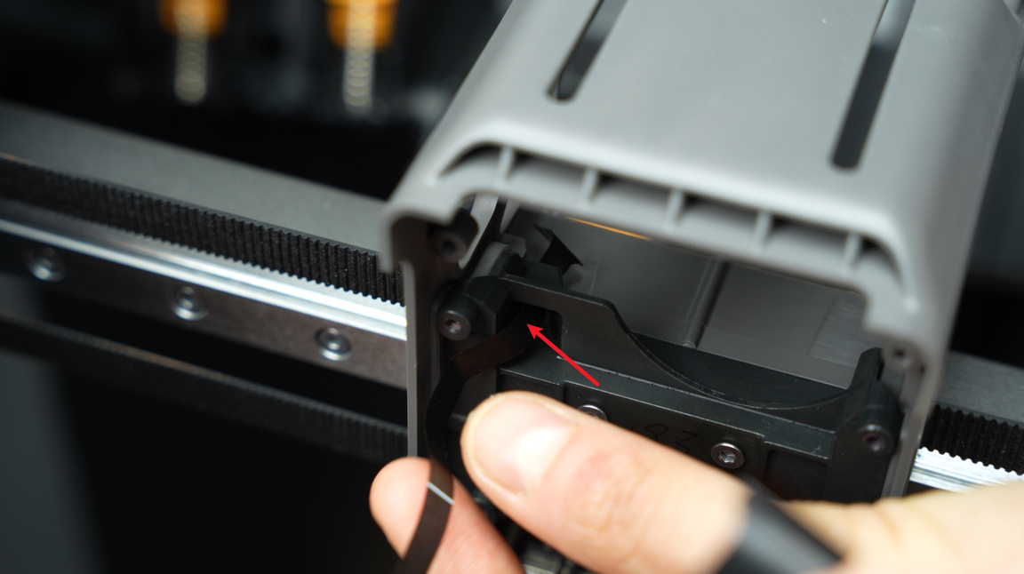
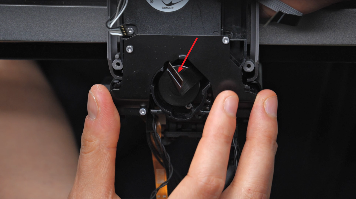
Ensure that the nozzle camera FPC cable is not stuck to the back cover of the lift motor, then use a tweezer to pry open the back cover of the lift motor.
 |
 |
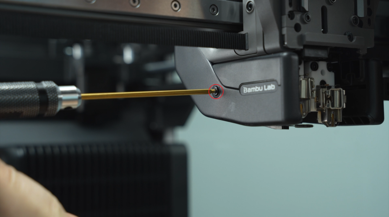
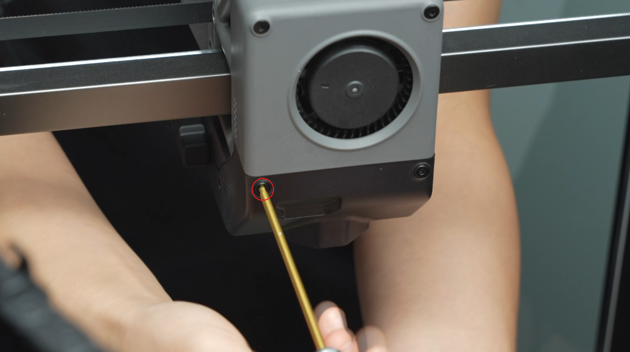
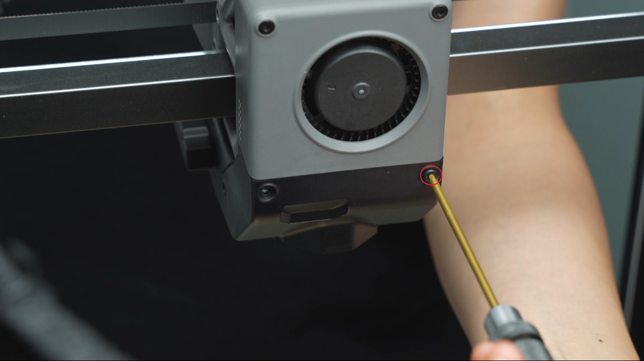
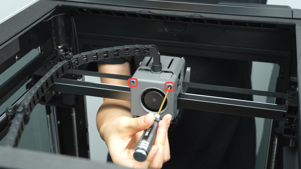
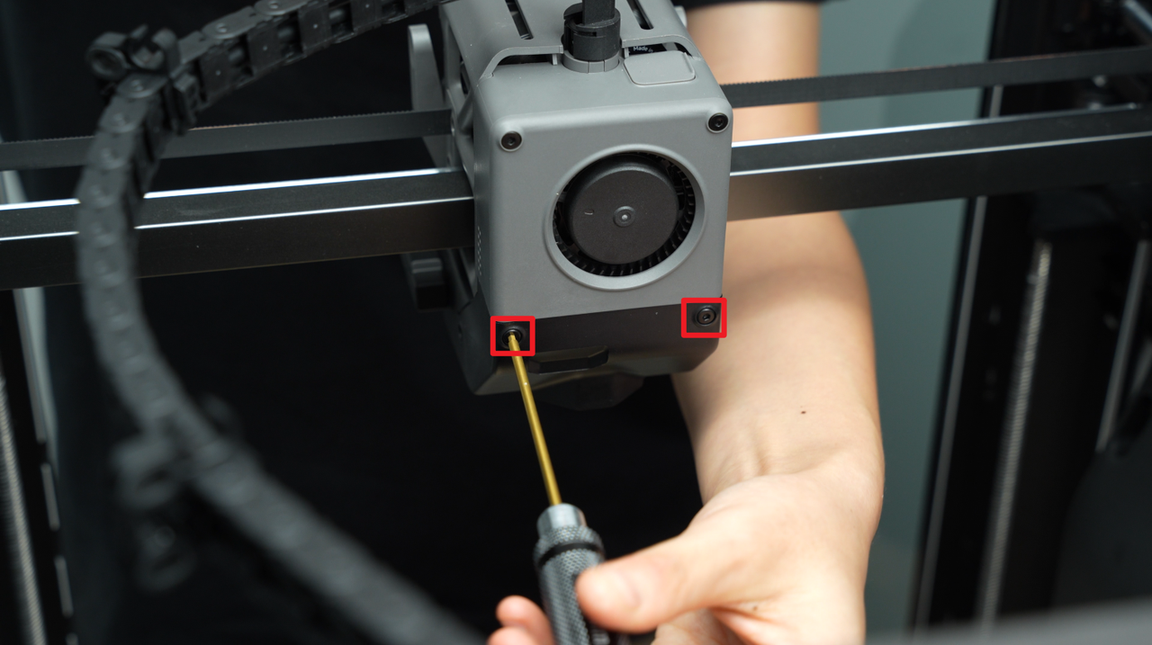
Unscrew the two fixing screws of the hotend fan, which are located inside the plastic frame groove. Insert the Allen key in the direction shown in the diagram to loosen them. It is strongly recommended to use an Allen key with a magnetic tip for this task. If the Allen key is not magnetic, you can magnetize it using the magnet on the hotend.
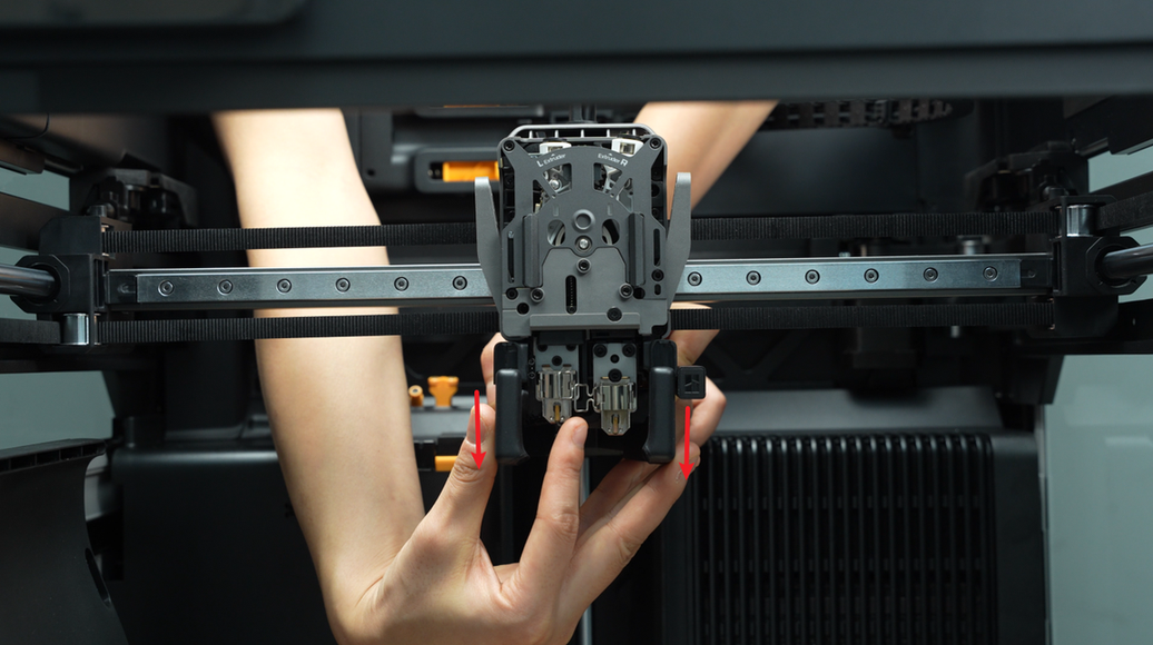
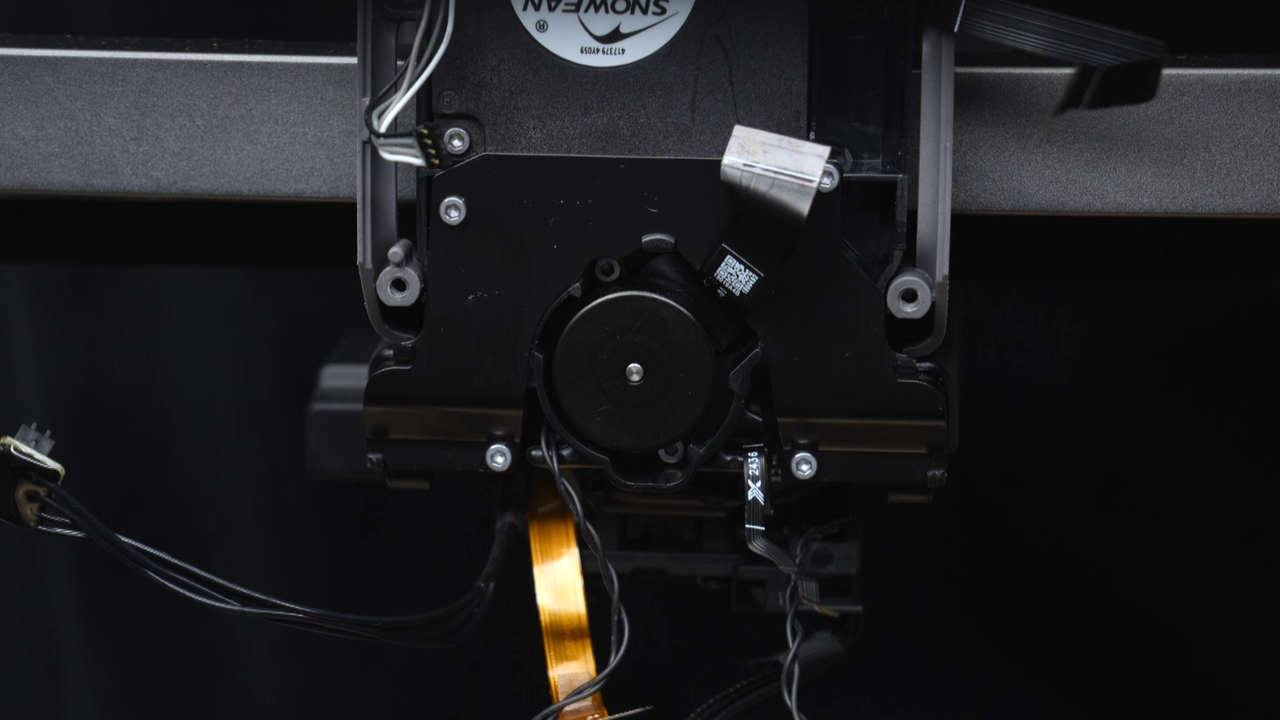
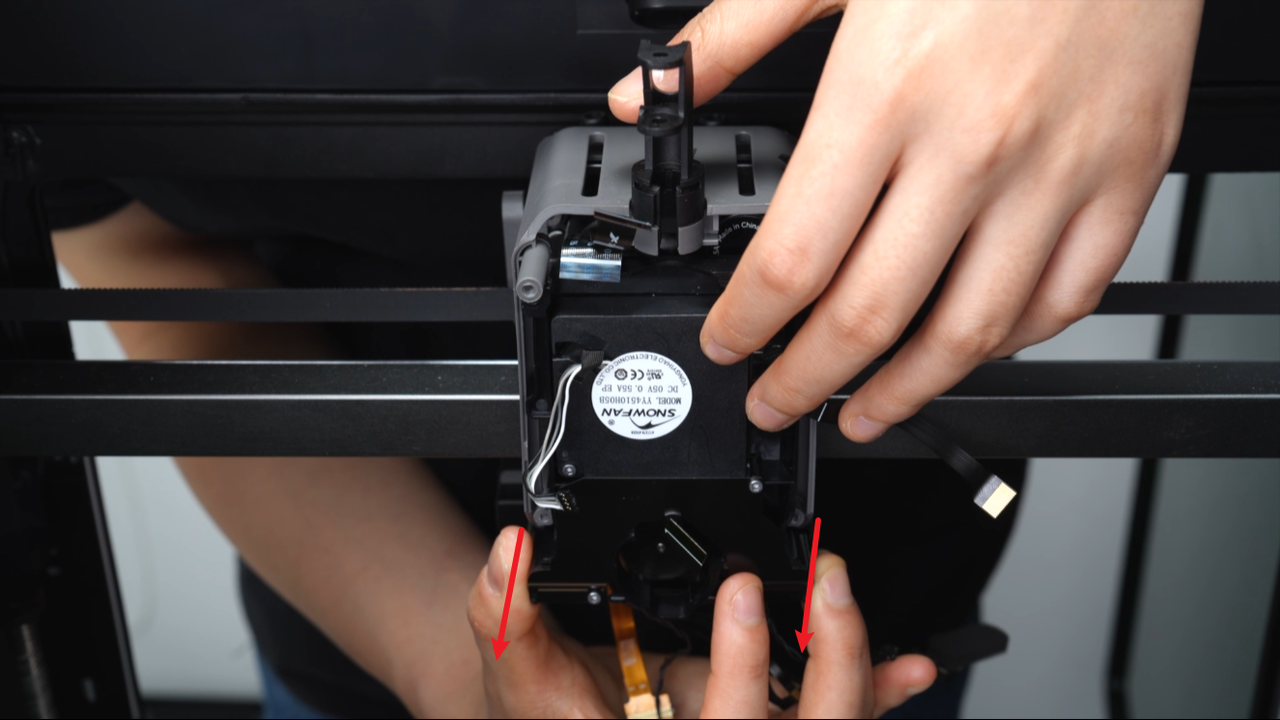
Grasp the lower part of the hotend fan and push it backward to remove the hotend fan.
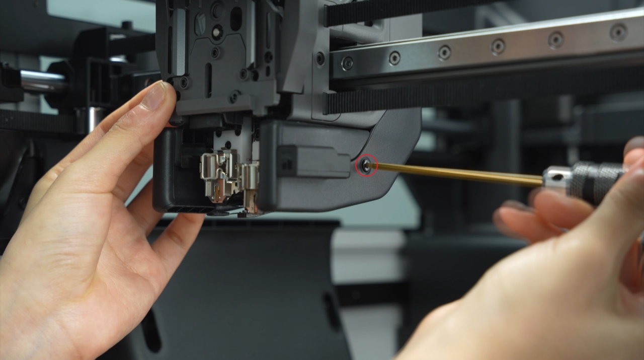
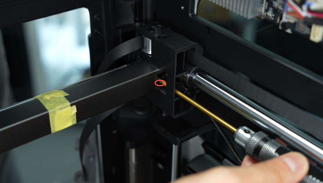
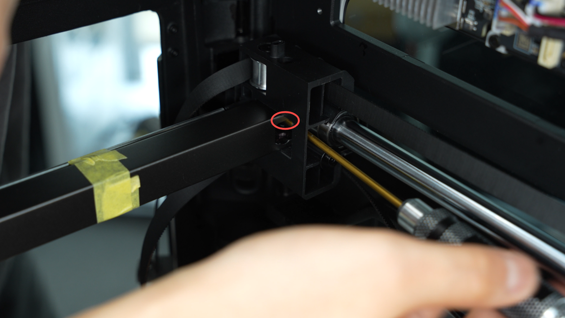
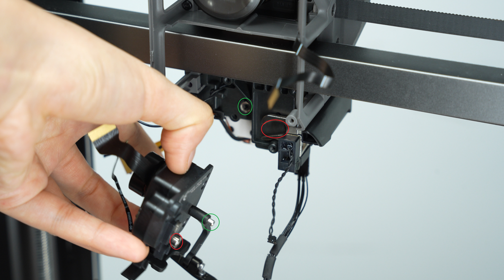
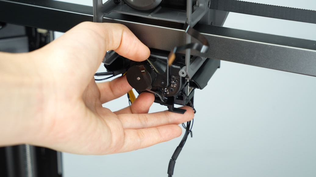
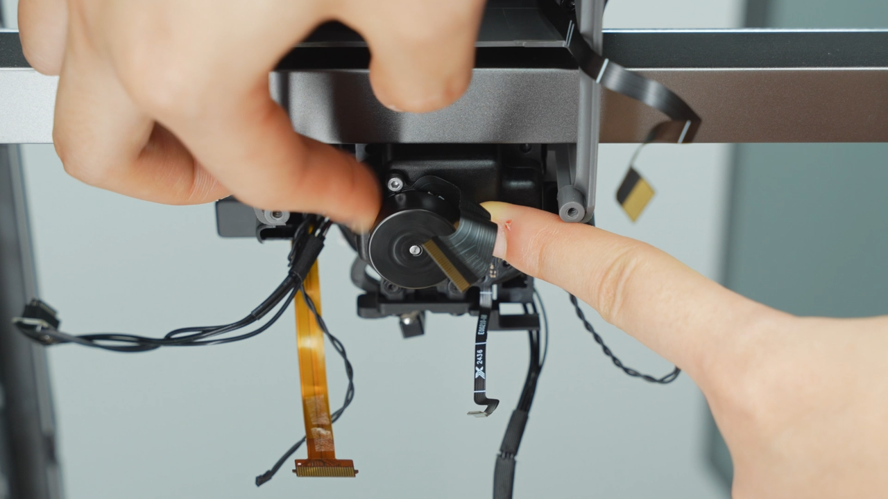
¶ Step 11 - Remove the lifting motor unit
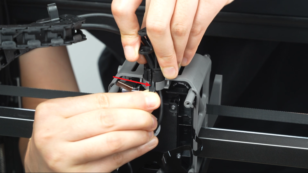
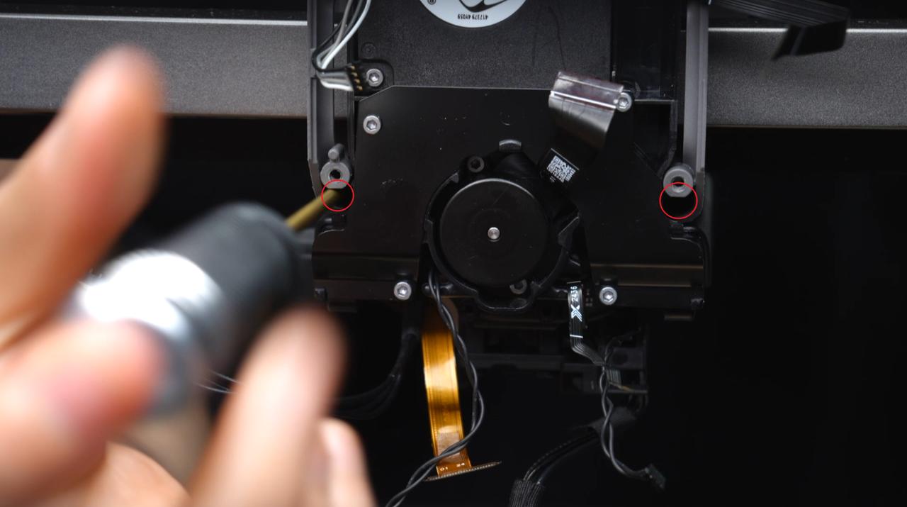
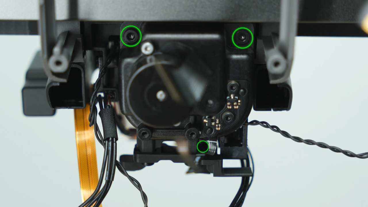
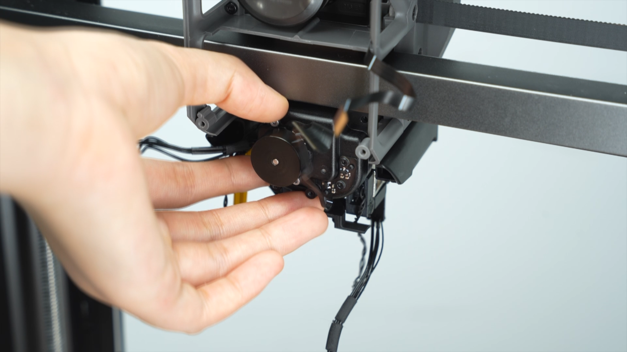
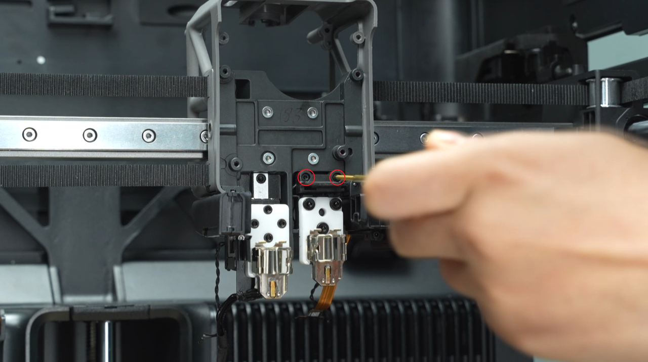
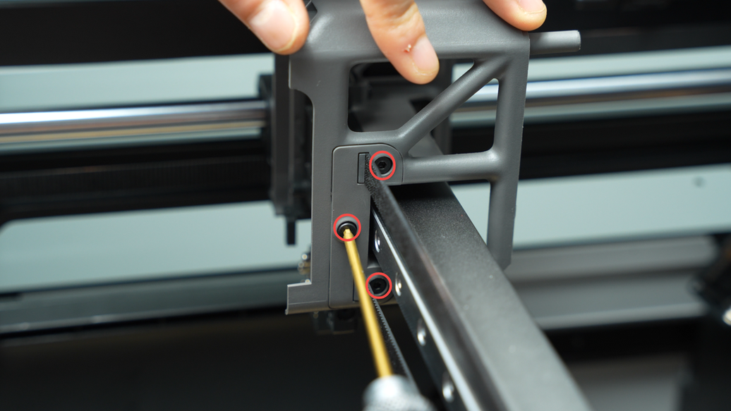
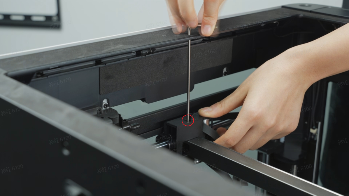
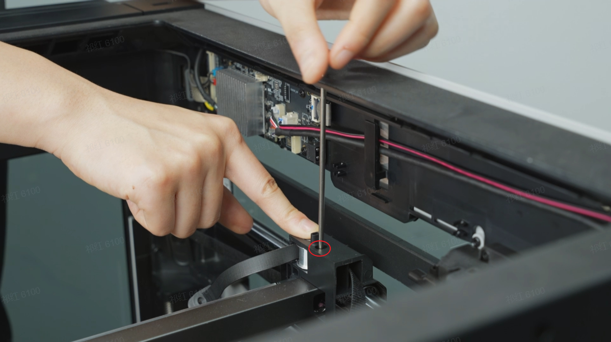
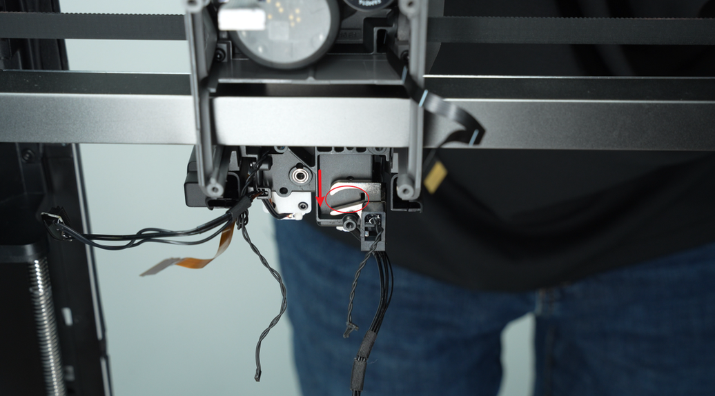
Unscrew the three screws, push back and remove the lifting motor. The bottom screw, which is not easily visible, is located below the FPC cable as shown in the diagram.
 |
 |
¶ Step 12 - Remove the dual extruder unit
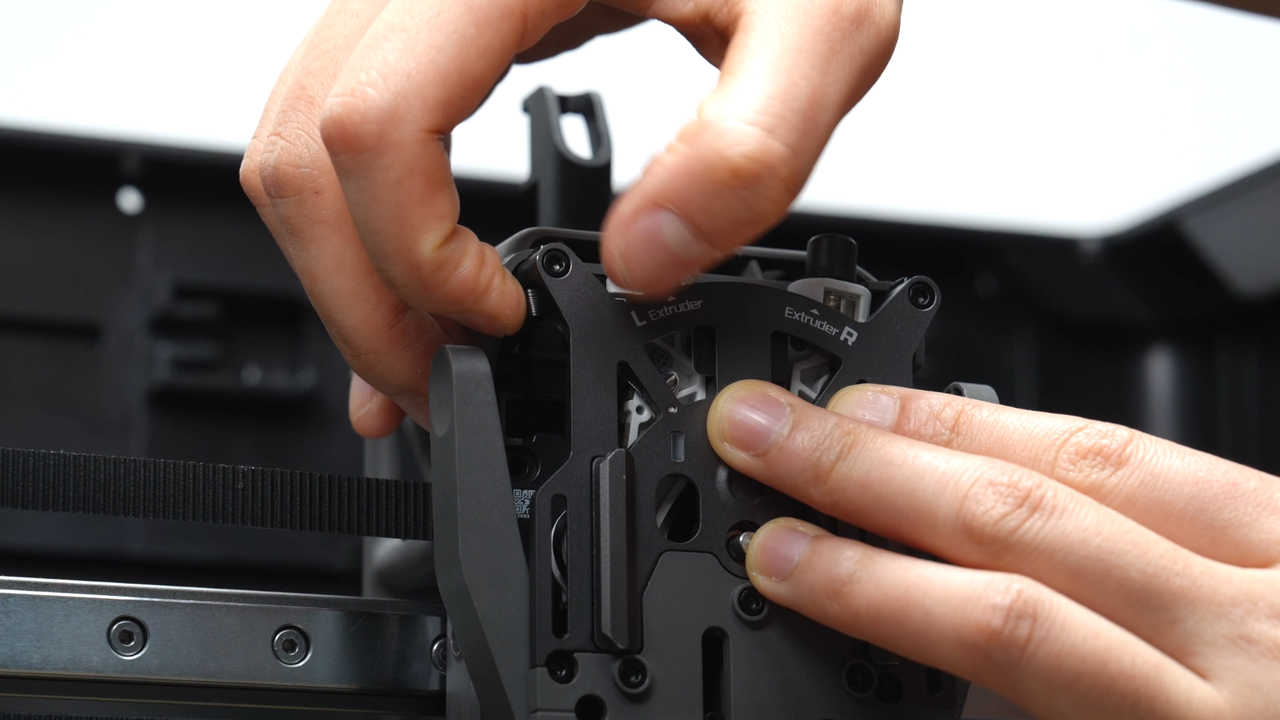
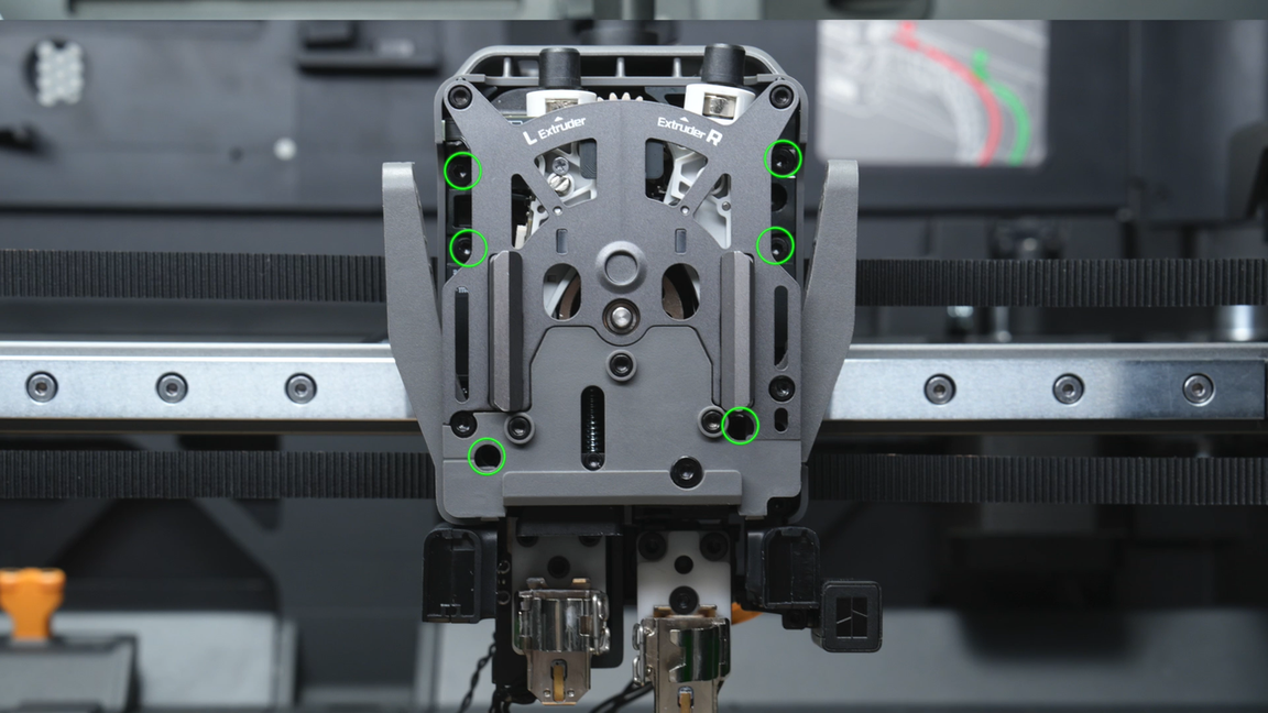
Use an H2.0 hex key to remove six fixing screws (the top two screws: BT2.6x8 * 2, and the remaining four screws: M2.5x8 * 2). When unscrewing the two screws at the bottom of the extruder filament guide, hold on the cutter first and then remove the screws.
As the two screws at the bottom of the extruder filament guide are located deep, loosening them completely may cause them to fall near the cutter and the extruder filament guide. If this situation occurs, gently shake the extruder to retrieve these screws after removing the extruder unit.
 |
 |
 |
 |
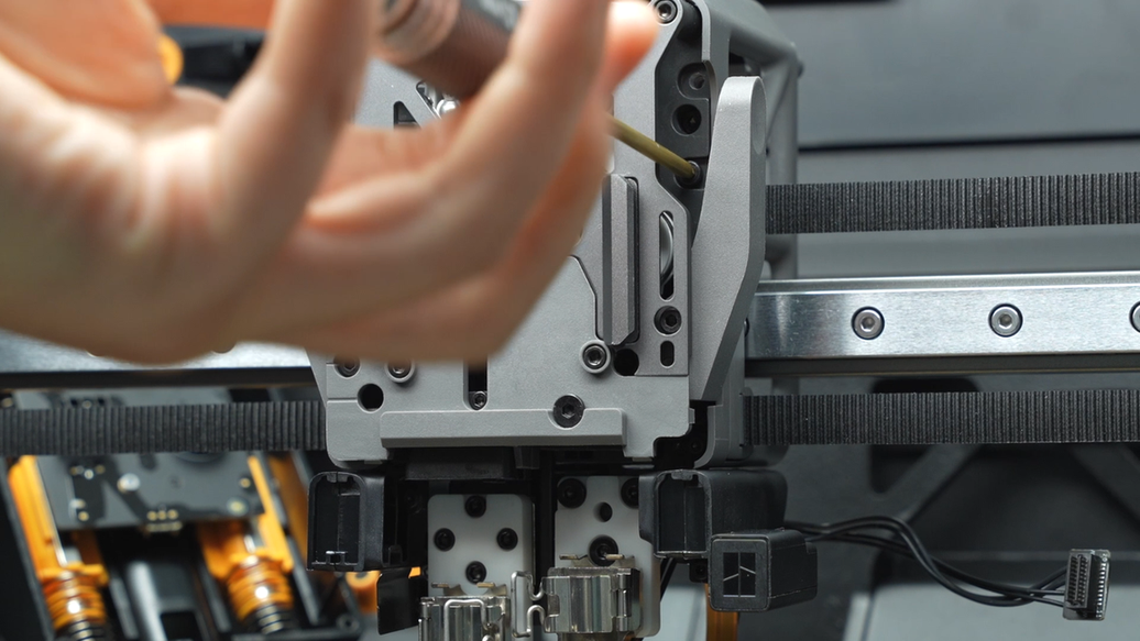
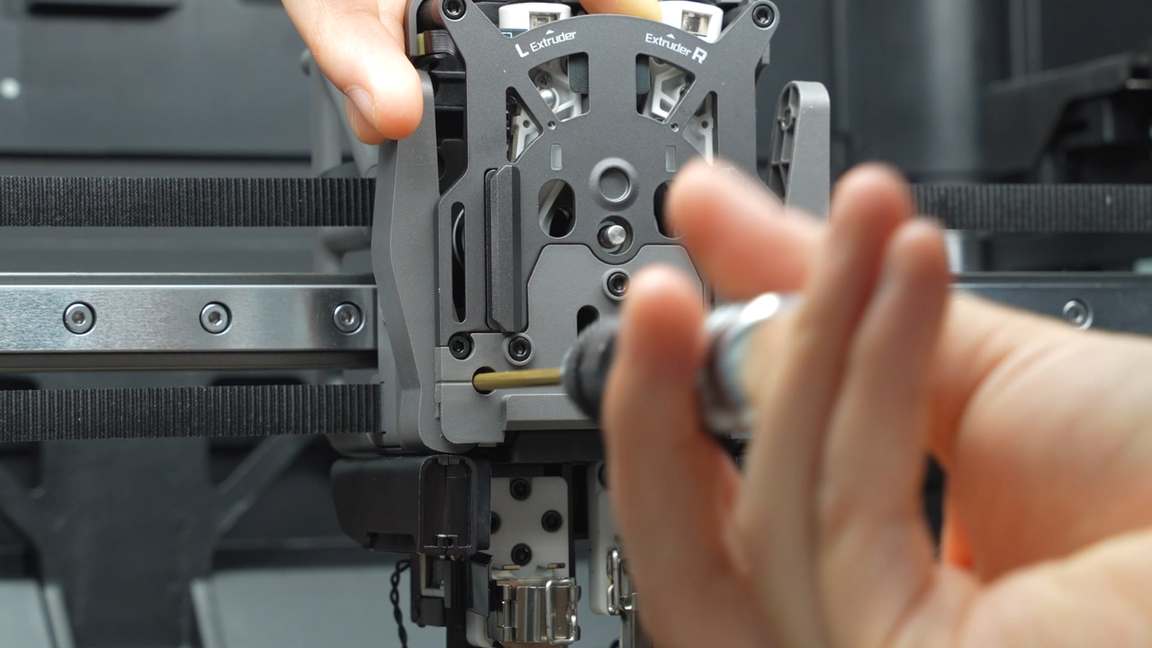
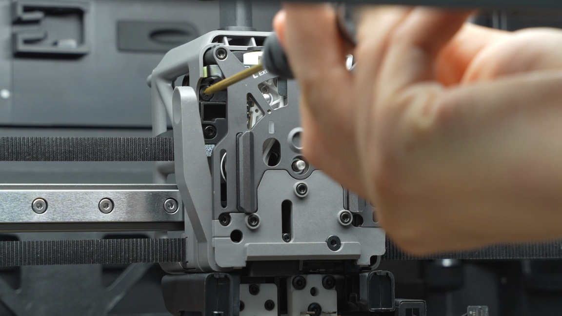
When removing the extruder unit, you can use a tweezer to flatten the internal cables from the gap above the tool head to prevent the cables from bending and hindering the removal of the extruder unit.
Then, flatten the cables at the back and push the extrusion motor cover outward with your fingers to remove the extruder at an inclined angle, avoiding interference between the extrusion motor cover and the middle frame. Finally, remove the extruder Hall sensor cable.
 |
 |
 |
 |
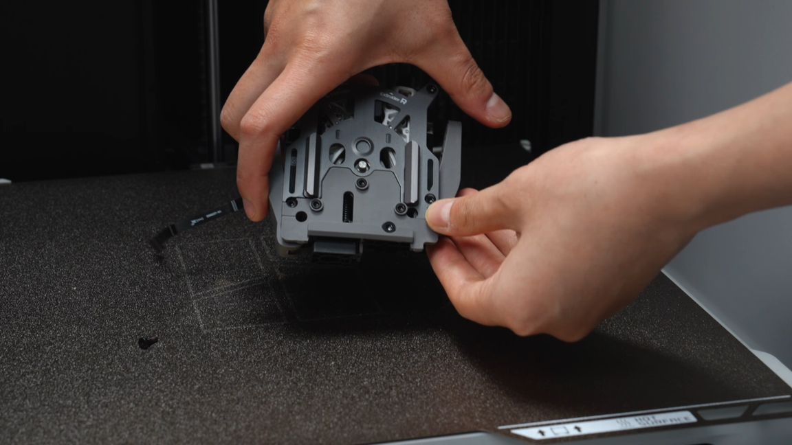
Gently shake the disassembled extruder unit above the heatbed to shake out any internal screws. Afterwards, organize and store all the screws properly to prevent loss.
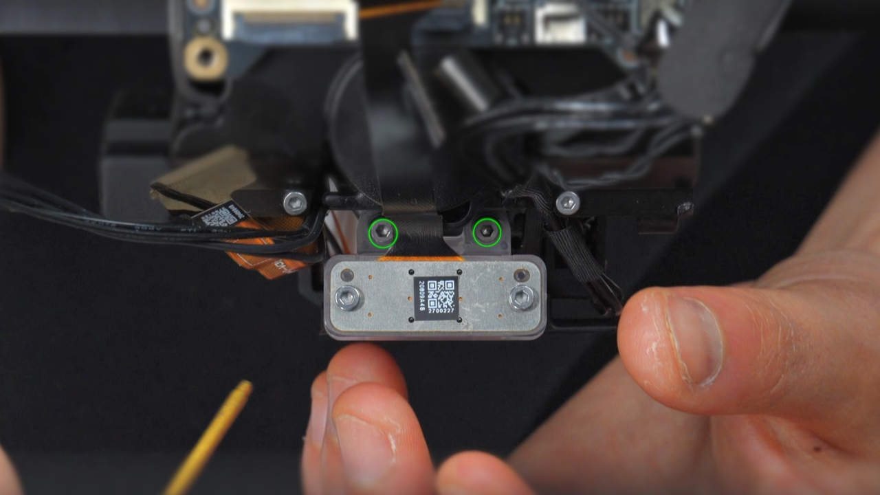
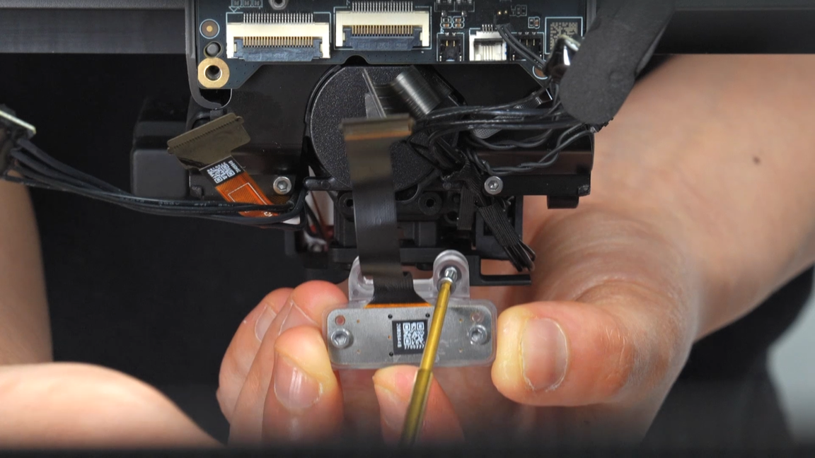
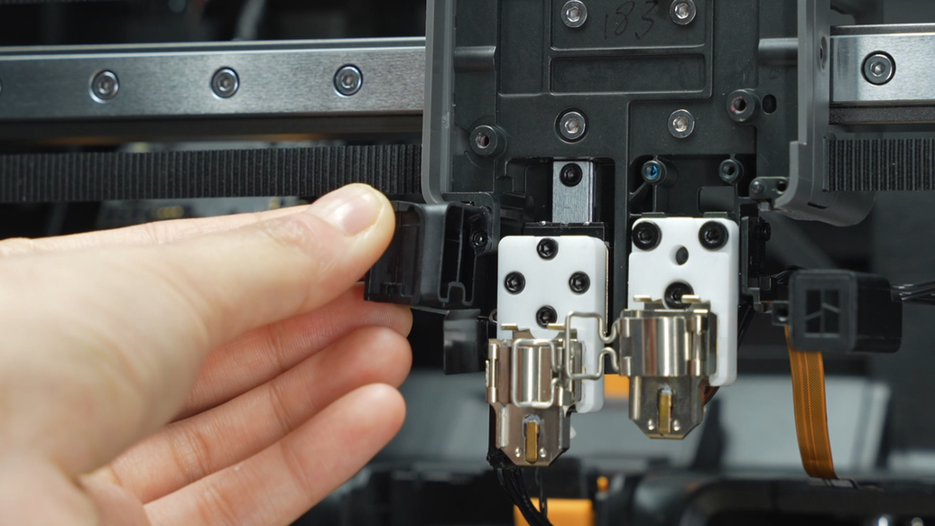
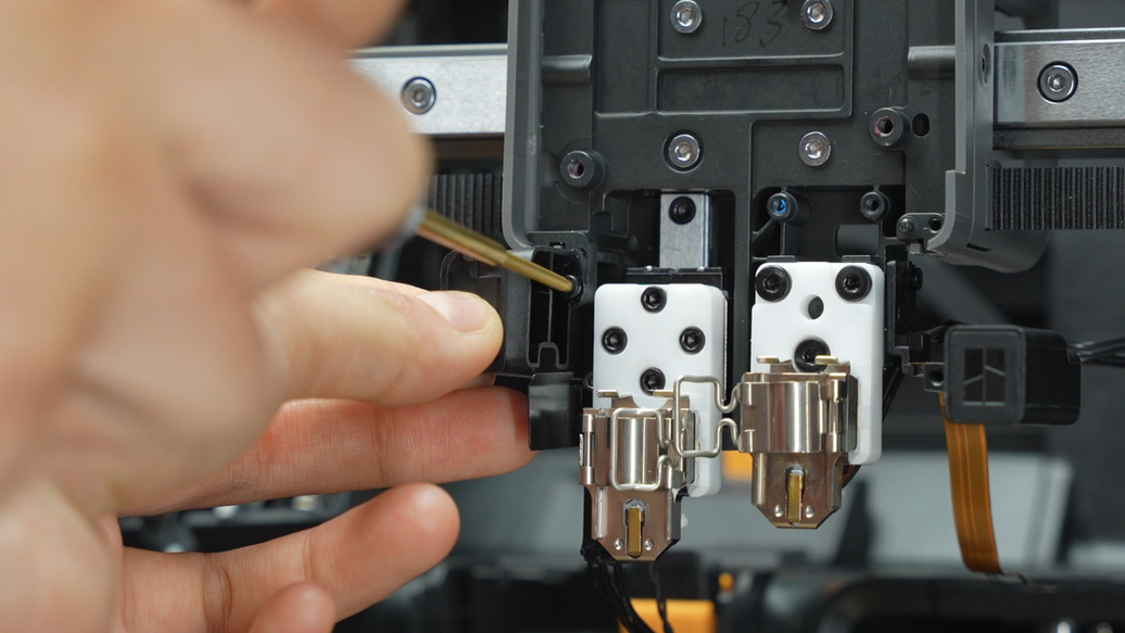
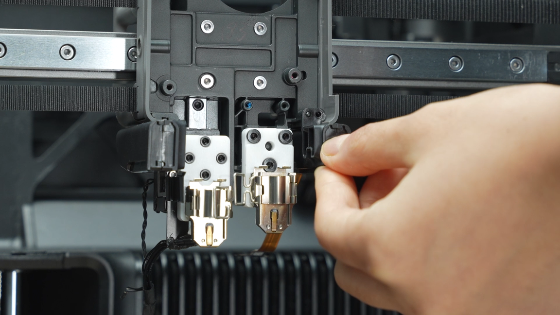
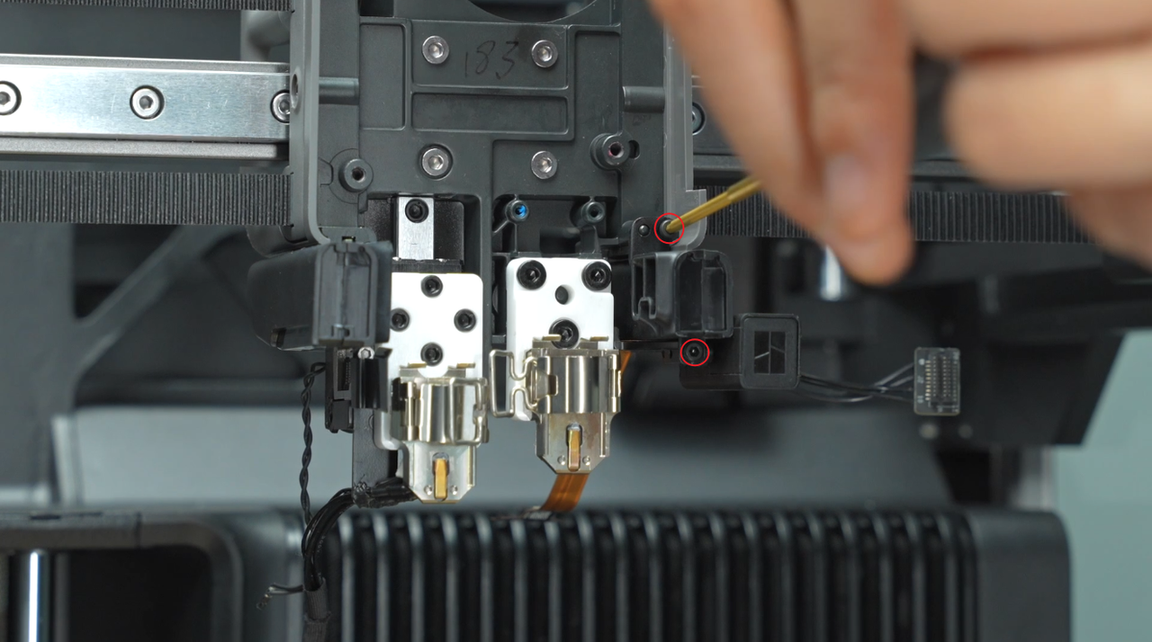
¶ Step 13 - Remove the right eddy sensor
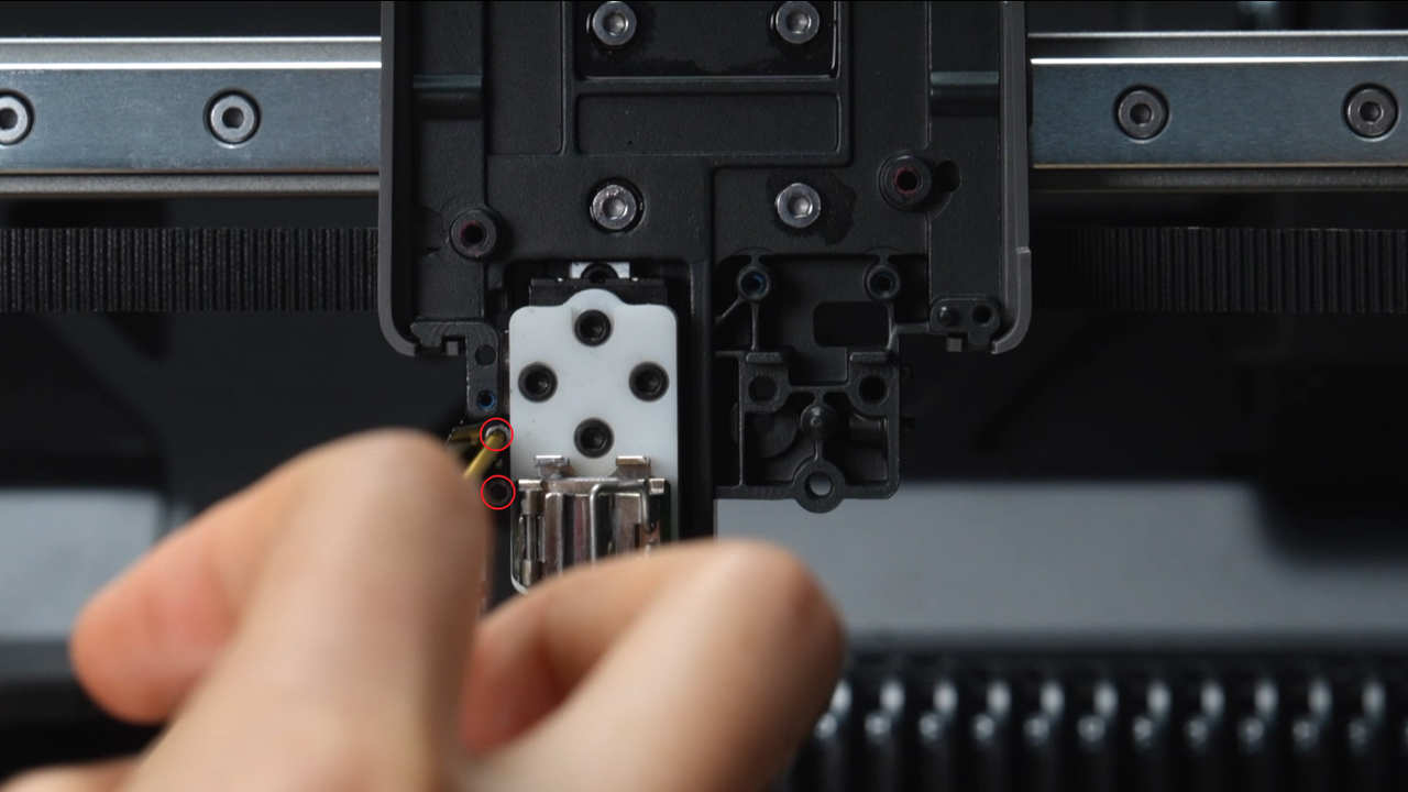
Unscrew the two screws, tidy up and support the rear cables, and remove the right eddy sensor.
 |
 |
¶ Step 14 - Remove the left and right hotend fan air ducts
The left hotend fan air duct is secured by one screw, while the right hotend fan air duct is secured by two screws. Unscrew the three screws to remove the left and right hotend fan air ducts.
 |
 |
 |
 |
¶ Step 15 - Remove the toolhead camera
Remove the two screws of the toolhead camera. After pulling out the cables of the right hotend heating assembly, remove the toolhead camera.
 |
 |
 |
 |
¶ Step 16 - Remove the left and right hotend heating assembly
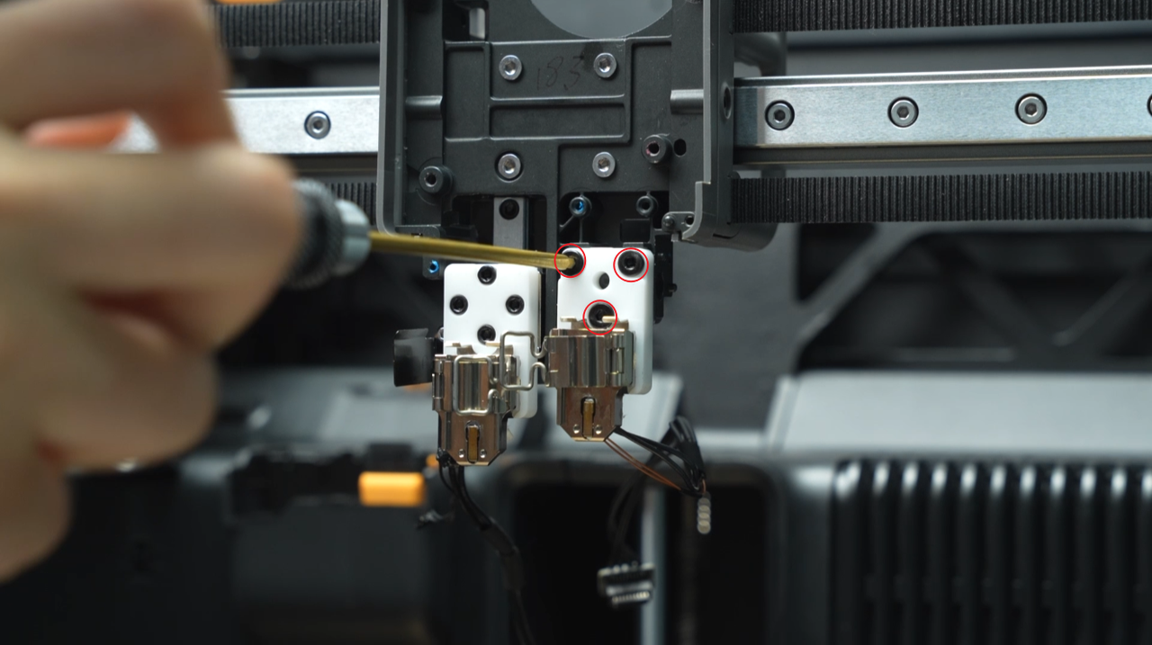
Remove the three screws of the right hotend heating assembly, then remove the right hotend heating assembly.
 |
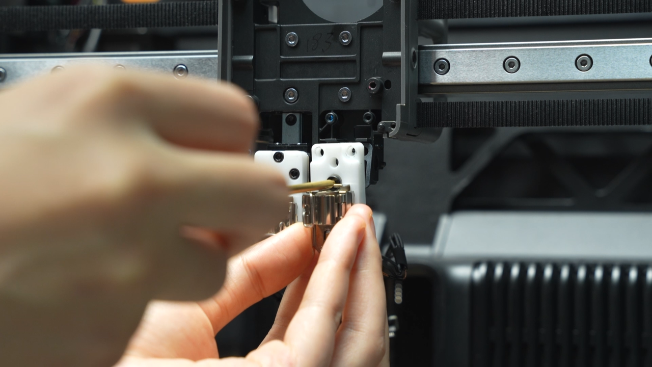 |
Remove the 2 screws that secure the wind blocker and cable blocker together, then remove the 4 screws of the left hotend heating assembly to take it off.
 |
 |
 |
 |
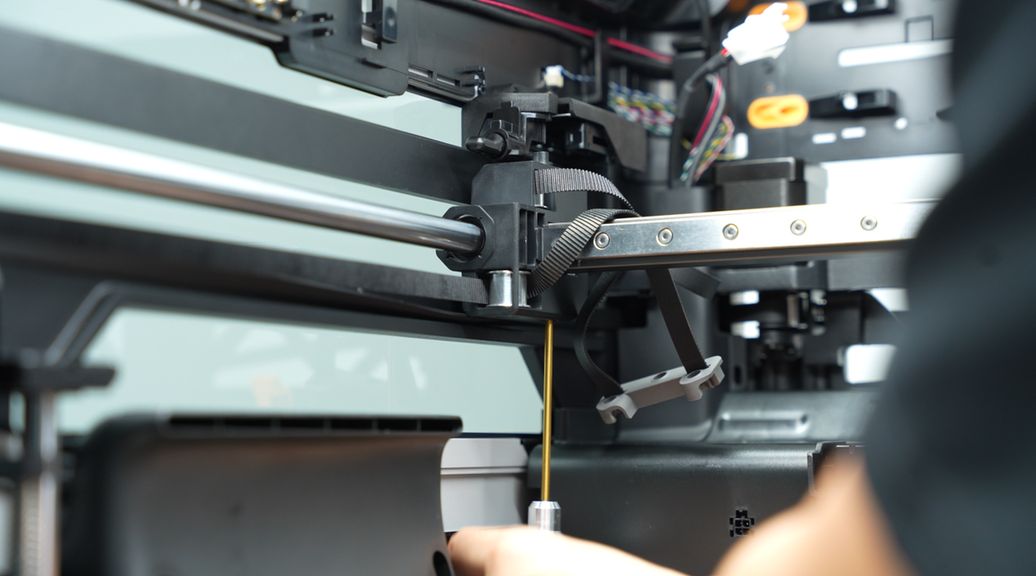
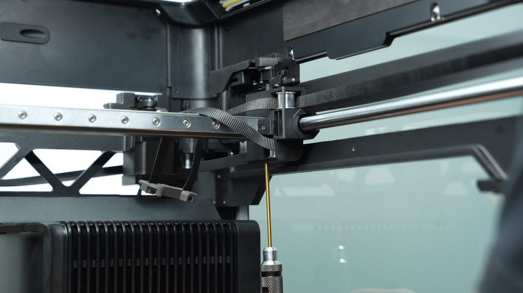
¶ Step 17 - Remove the X-axis assembly
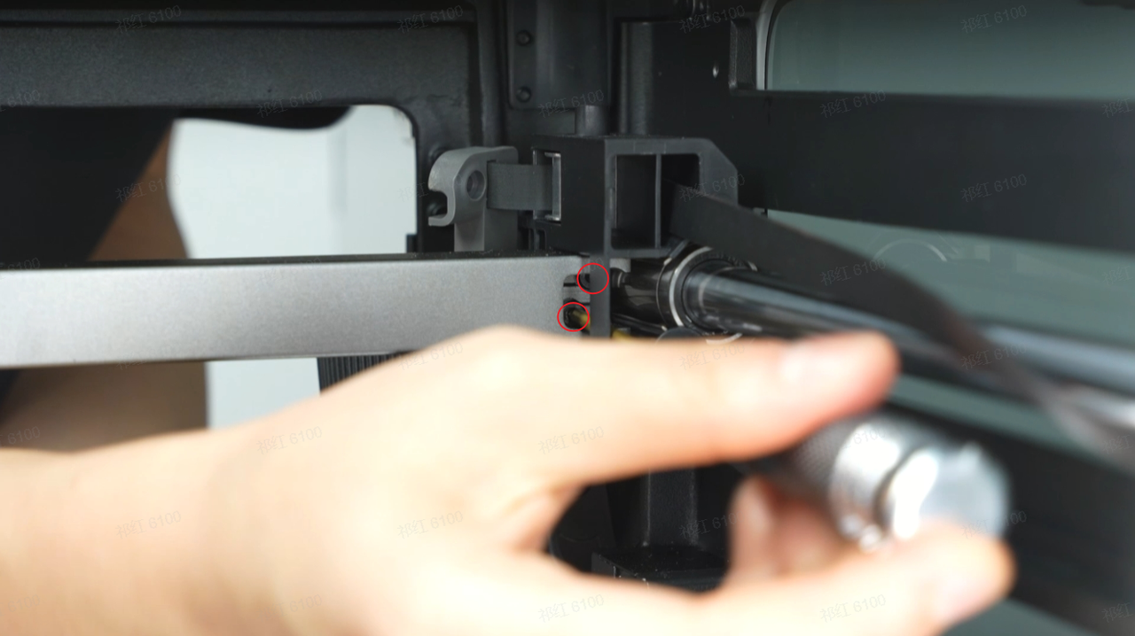
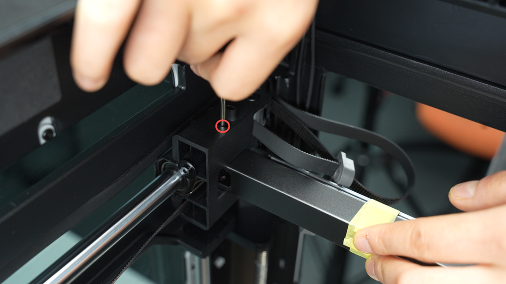
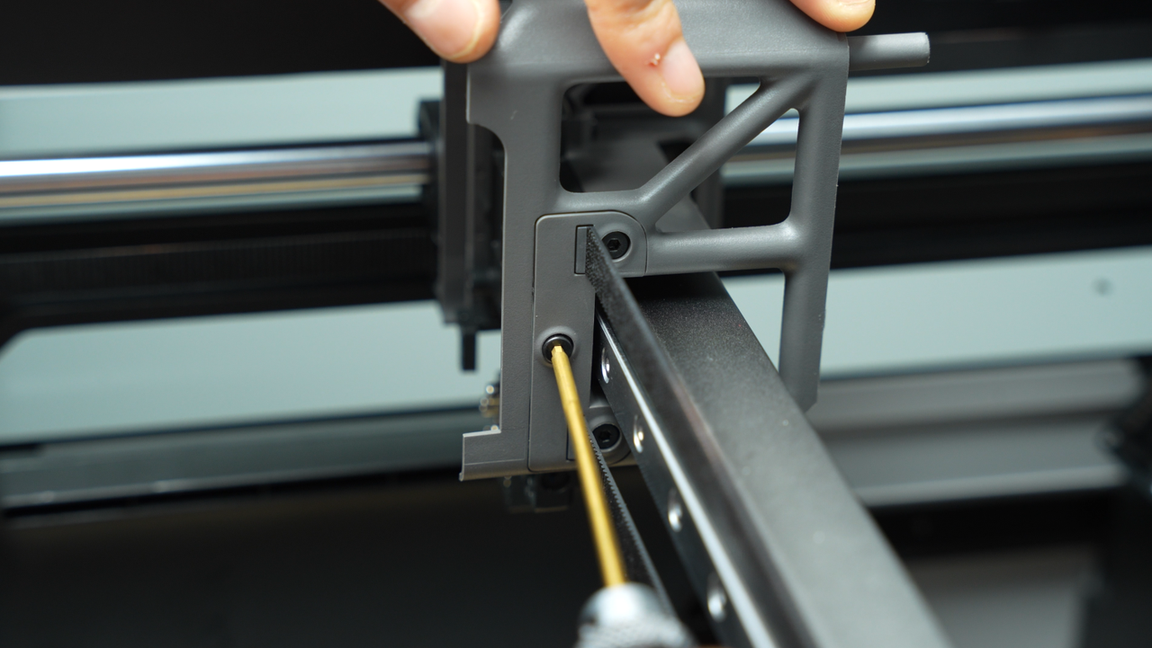
Unscrew a total of 6 screws from the belt brackets on both sides of the toolhead.
 |
 |
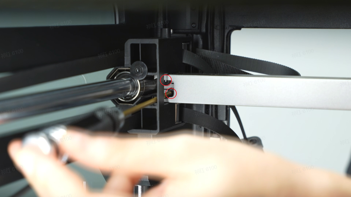
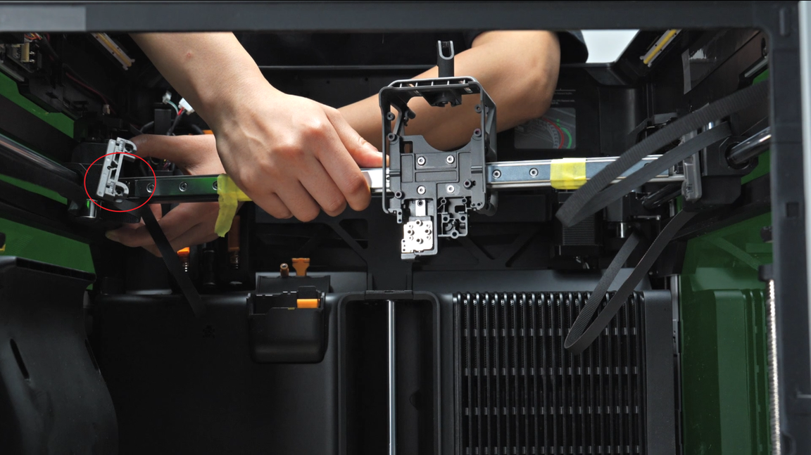
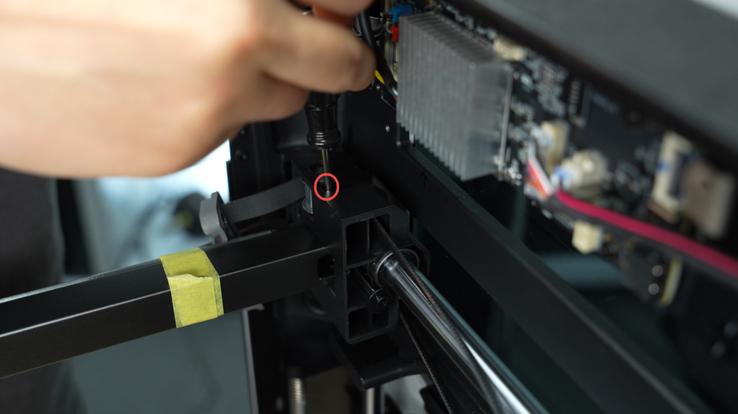
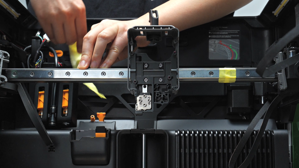
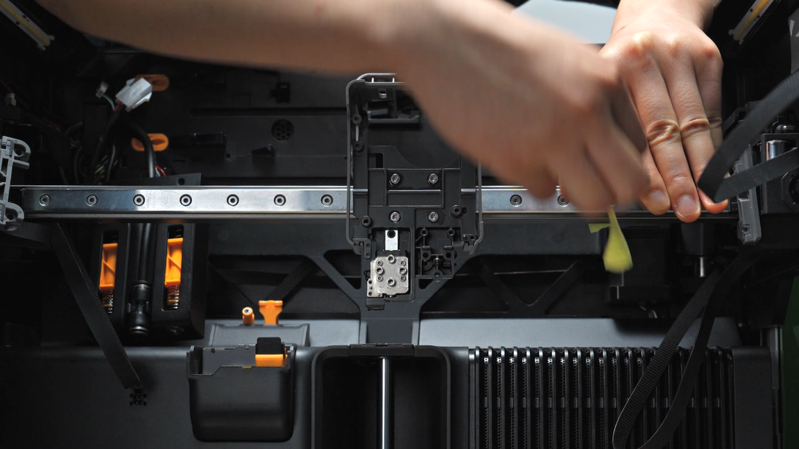
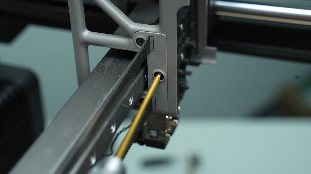
Next, you will need to remove a total of 8 screws that secure the rail carriage and linear guide - 4 screws on each side.
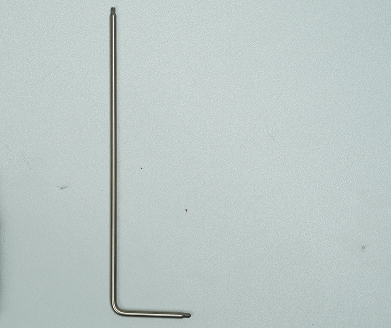
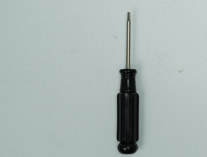
This step requires a high-quality tool for the wrench head, as a good tool can significantly enhance your disassembly experience. If you lack a very good tool or do not have sufficient strength to apply the torque needed to turn the screwdriver, it is recommended to use the L-shaped wrench provided in the accessory box and the short handle flathead screwdriver included in the spare parts. Additionally, magnetize the screwdriver head using a magnet on the hotend, following the suggestions in this guide, to successfully loosen these 8 screws.
 |
 |
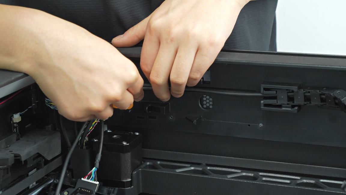
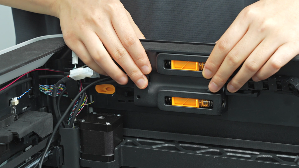
Use a tweezer or a flat tool to pry open the covers of the left and right LED lights. You can use your thumb to press down on the top cover frame to slightly deform the light cover, making it easier to insert the tool for prying.
 |
 |
 |
 |
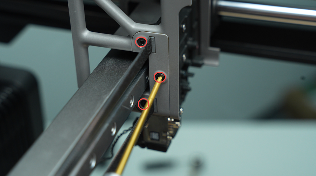
Use an Allen key to poke a small hole in the foam pad at the center of the top cover frame. Move the rail carriage to the center and insert an L-shaped wrench. With the short end of the L-shaped wrench, unscrew and remove the screw.
 |
 |
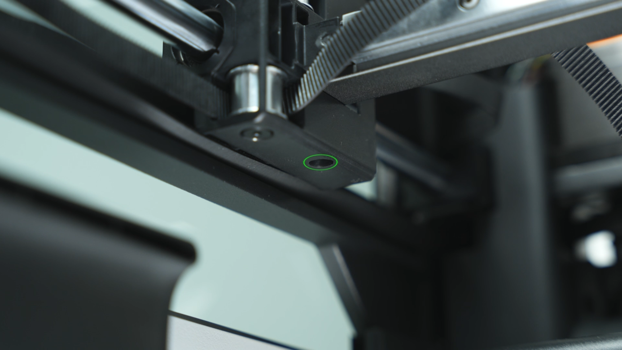
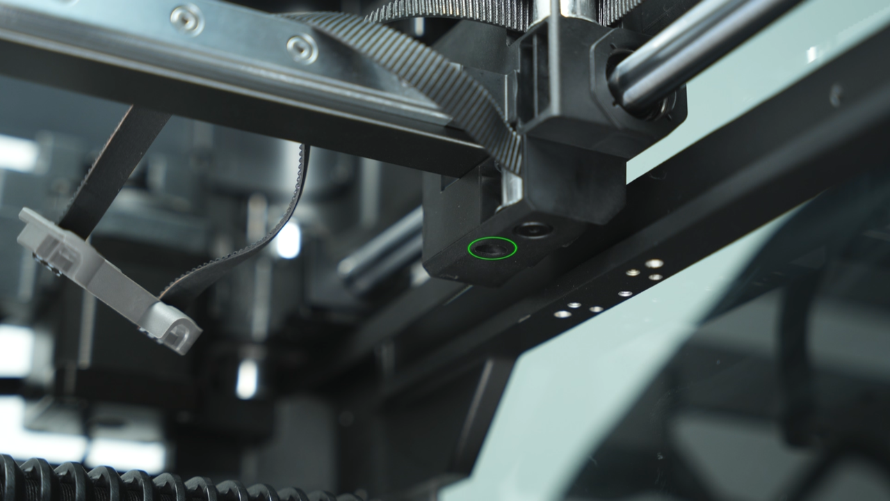
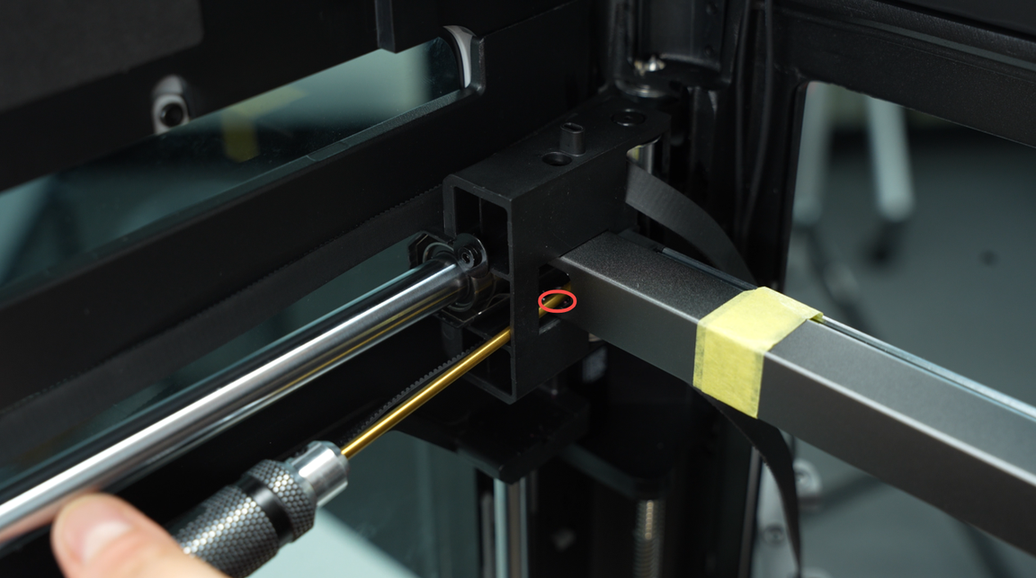
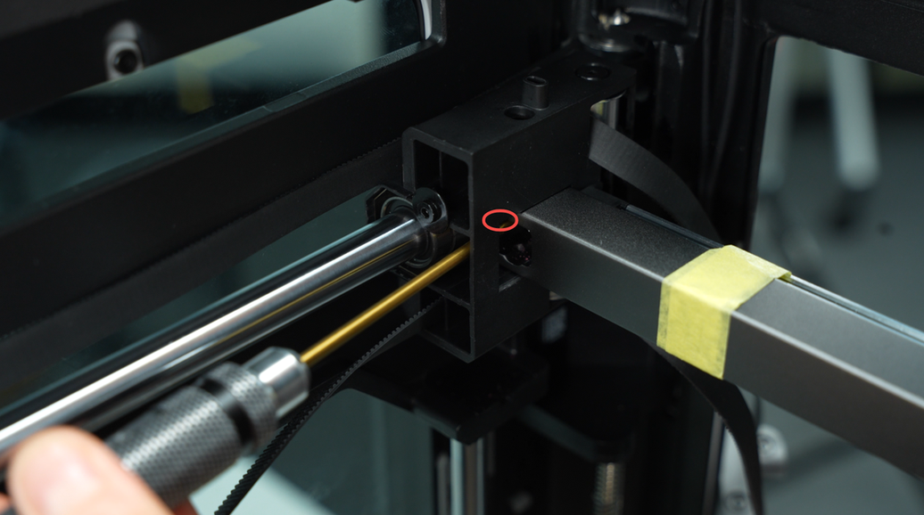
Then, remove the four screws on the side of the linear guide and the two screws on the bottom of the carriage.
 |
 |
 |
 |
After removing all the screws, you can remove the X-Axis assembly. When removing the X-Axis assembly, first detach the right side of the linear guide from the carriage, then detach the left side of the linear guide from the carriage, and tilt to remove the X-Axis assembly.
 |
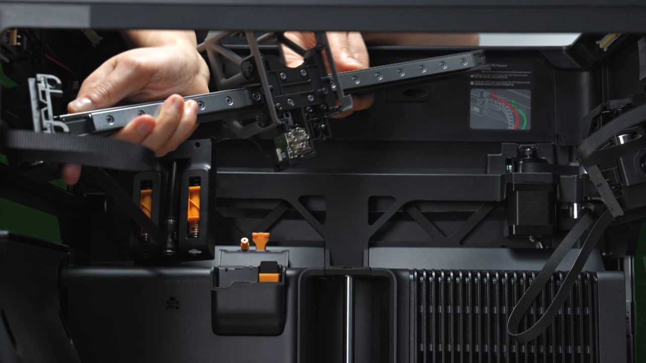 |
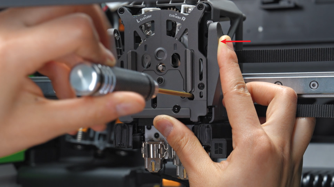
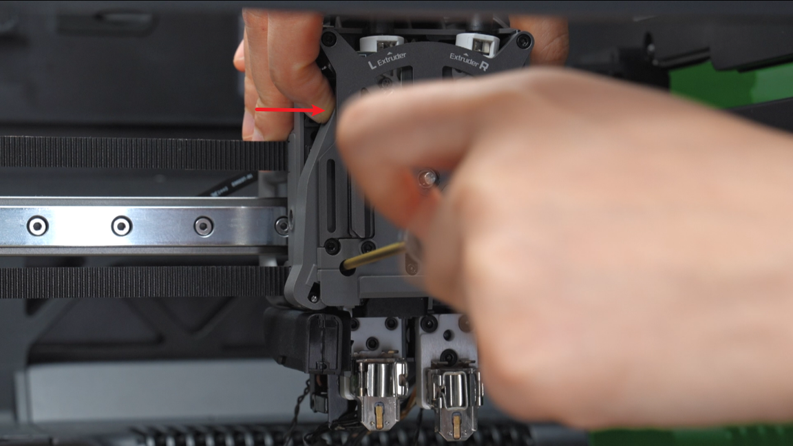
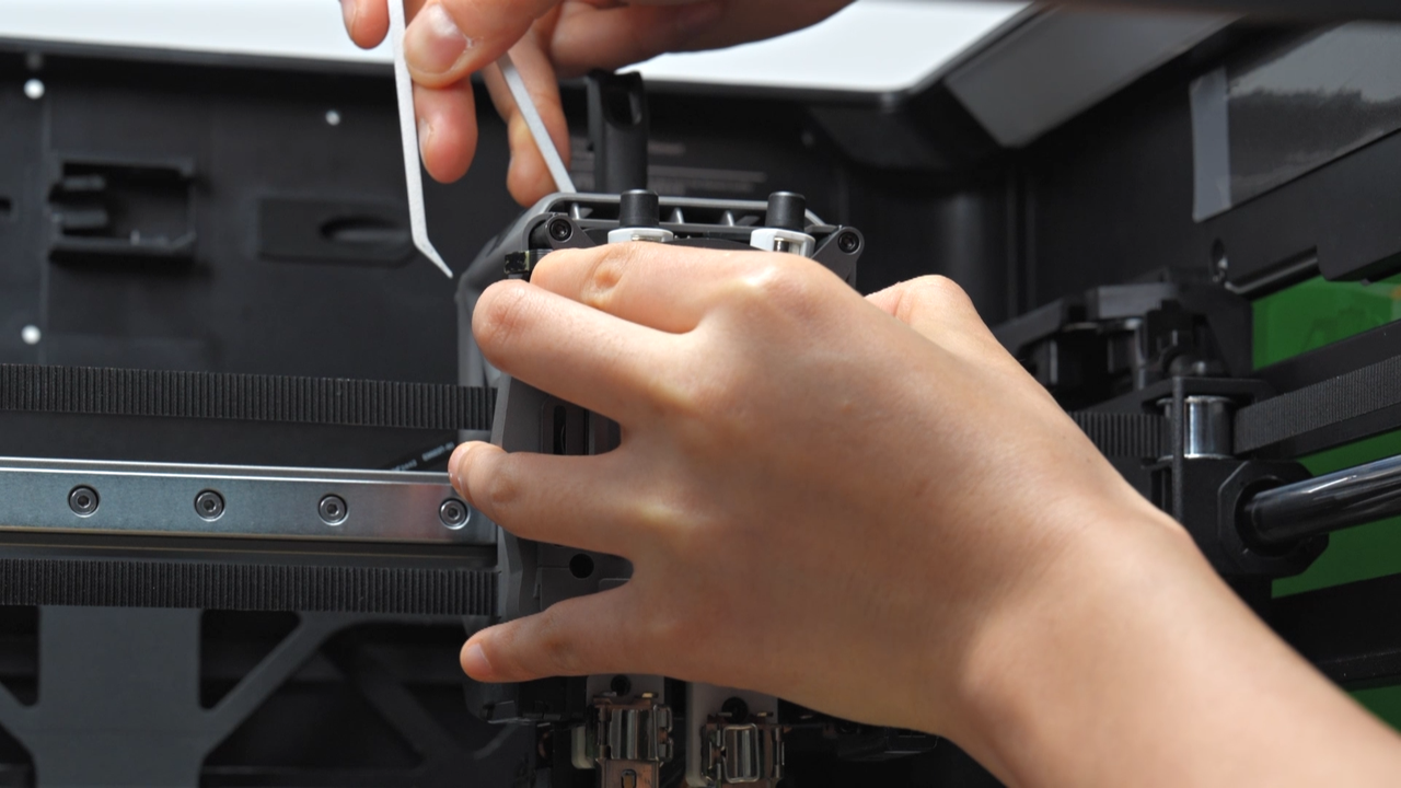
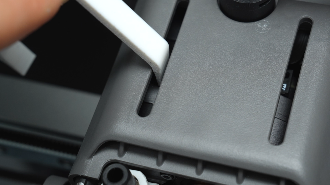
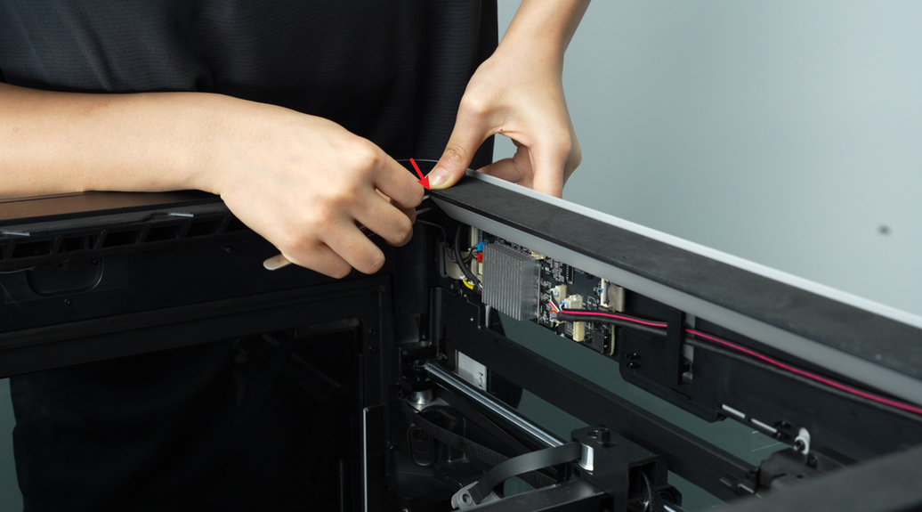
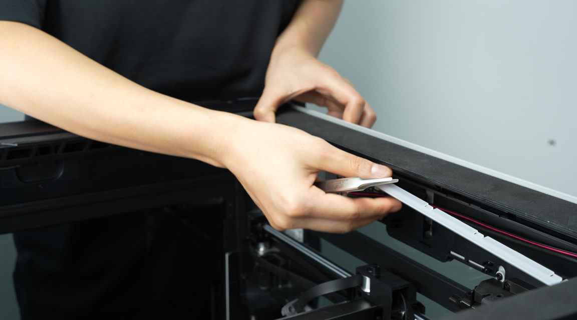
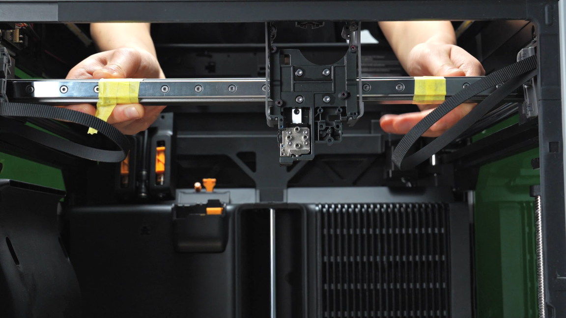
Apply traceless tape on both sides of the tool head. If traceless tape is not available, you can place some paper strips on the X-Axis assembly and then stick them with transparent tape. The purpose of this step is to restrict the movement of the tool head and prevent it from sliding out directly when removing the X-Axis assembly.
 |
 |
¶ Assembly Guide
¶ Step 1 - Install X-axis Assembly
Move the rail carriages along the Y-axis so that the two carriages are staggered (one in front of the other). Manually align the carriages to ensure they are level. Insert the linear rails into the carriages.
 |
 |
Push the rail toward the front door until it stops, and use the hard frame at the front door to limit the position to ensure that the rail is in a completely horizontal state.
Screw in the left and right screws above the rail to secure the rail. It is recommended to use the short-handled screwdriver included in the spare parts and use a magnet to magnetize the screwdriver head.
 |
 |
 |
 |
Then screw in the two screws on the sides one by one. If you forget the screw hole position, refer to the steps for removal.
 |
 |
 |
 |
Screw in one screw on each side of the rail to completely tighten the rail.
 |
 |
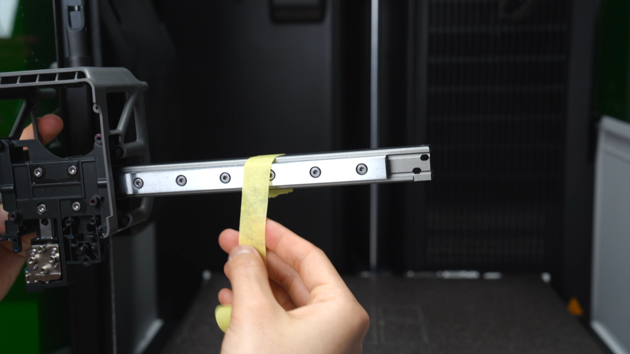
Tear off the anti-slip masking tape on both sides of the rail;
 |
 |
Align the buckle at the bottom and press in the LED covers on both sides.
 |
 |
Lock the 6 screws of the belt locking blocks on both sides of the nozzle lifting rail bracket. Since the belt has a certain tension, when installing the 3 screws on the left, you can slide the toolhead to the far right, use the frame as a support point, and press the belt locking block hard. Similarly, when installing the 3 screws on the right, you can slide the toolhead to the far left.
 |
 |
¶ Step 2 - Install the left and right hotend heating assemblies
Install the cable sheet according to the positioning pillar (the cable sheet is connected to the left hotend heating base), and install the left hotend heating base at the same time, align the screw holes, and tighten the 4 screws. Note that the base needs to be installed in place, flush and without gaps. If the screws are not smooth, you can shake the base slightly or replace the screws.
 |
 |
Install the windshield, and then tighten the 2 screws. Please pay attention to the installation order, install the cable sheet first, so the cable sheet should be under the windshield.
Install the right hotend heating base insulating sheet and base, make sure the base is attached to the two black limit blocks above and is level, align the screw holes, and tighten the three screws.
 |
 |
Visually check that the left and right hotend heating bases are parallel, then tighten the three screws.
 |
 |
 |
¶ Step 3 - Install the toolhead camera
Insert the cable of the right hotend heating assembly into the cable slot of the toolhead camera bracket. After inserting, move the cable back and forth so that the thicker cable with the rubber sleeve is close to the notch to prevent the cable from falling out in the future.
Use the positioning holes to install the camera bracket, align the screw holes, and lock in two screws.
 |
 |
¶ Step 4 - Install the left and right hotend fan air ducts
Install the left hotend fan air duct according to the positioning holes, align the screw holes, and tighten one screw.
 |
 |
Install the right hotend fan air duct according to the positioning holes, align the screw holes, and screw in the two screws.
 |
 |
¶ Step 5 - Install the right eddy sensor
Pass the cable of the eddy sensor through the hole above the right hotend heating base to the back of the toolhead. Install the right eddy sensor according to the screw hole positioning and lock in the 2 screws.
 |
 |
¶ Step 6 - Install the dual extruder unit
Pass the extruder Hall cable on the dual extruder unit through the square hole on the bracket to the back of the toolhead.
When installing the dual extruder unit, please be careful to avoid damaging the 3 FPC cables. You need to press down the switching motor FPC first to prevent the cable from curling up and interfering with threading. After installation, there will be a clear sense of being in place, and the gears will not protrude. The limit points on the left and right sides are in contact with the plastic middle frame, and 6 screws (2 types) are locked in.
 |
 |
Use an H2.0 Allen key to tighten the six fixing screws (the top two screws: BT2.6x8 * 2, the remaining four screws: M2.5x8 * 2). When installing the two screws under the dual extruder filament guide, you can hold down the cutter and then screw in the screws.
 |
 |
 |
 |
¶ Step 7 - Install the lifting motor unit
Close the left hotend heating base buckle and pull the hotend downward to slide the mozzle lifting rail down.
 |
 |
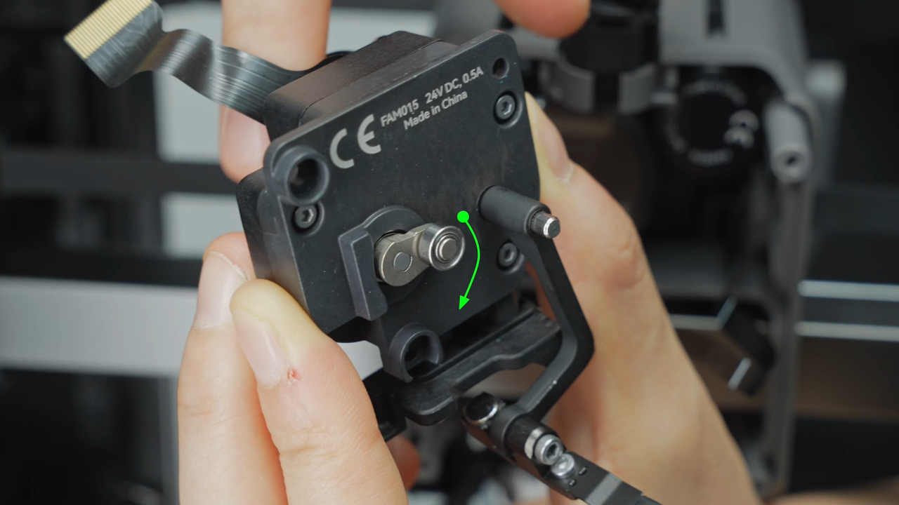
Manually rotate the rotor of the lifting motor so that the rocker arm of the bearing faces downward. Pull down the nozzle lifting rail on the toolhead so that the slider's vacant slot faces downward. The purpose of this step is to ensure that the rocker arm bearing can be smoothly embedded in the bracket when installing the motor.
 |
 |
Push the cables aside to prevent them from being pinched, align the bearing holes, and install the lifting motor unit onto the toolhead.
 |
 |
After installation, you can manually rotate the rotor of the lifting motor without tightening the screws first to observe whether the left hotend rises and falls normally and whether the flow blocker switches smoothly between the left and right hotends.
 |
 |
After confirming that the lifting function is normal, lock the three screws. The bottom screw is not easy to see and is located at the lower back of the lifting Hall FPC shown in the figure.
 |
 |
¶ Step 8 - Install the cooling fan for hotend
Install the cooling fan for hotend and pass the lifting motor cable through the hole of the fan bracket. Arrange the cables and push all other cables aside to avoid them being pressed. After installing the cooling fan, first confirm that each cable is not pressed before tightening the screws.
From top to bottom and from left to right, the cables that need to be checked in turn include: switching motor, extruder servo motor, 3-in-1 cable, toolhead camera, nozzle camera, left and right eddy sensors, lifting Hall and lifting motor cable (the last one passes through the hole behind the motor rotor).
 |
 |
Tighten the two screws and close the lifting motor cover.
 |
 |
 |
¶ Step 9 - Install the TH board, USB-C cable and cable chain
Insert the USB-C cable into the back of the TH board. Please note that when inserting, the side with the letter "T" must face upwards and make sure it is inserted into place (until it can't be pushed forward any further).
 |
 |
Insert the USB-C cable and toolhead to MC board cable into the toolhead cable chain bracket in turn. When inserting the cables, first insert a small section from the bottom and then push them in from the bottom to the top.
 |
 |
After making sure that the TH board is not hooked on any cables, pull 2 cables from the top of the toolhead and insert the plug of cooling fan for hotend at a suitable length. The metal side of the solder joint is facing up, and press it in from top to bottom. After pressing in, smooth it out with your fingers again to ensure that there is no poor contact. Then hide the fan cable from the notch near the socket into the back of the TH board.
 |
 |
 |
After ensuring that all other remaining plugs are not pressed by the TH board, use the screw holes to locate, install the TH board, and lock the two screws on the top. From top to bottom and from left to right, the cables that need to be checked in turn include: switching motor cable, extruder servo motor cable, TH connection board connector, extruder Hall cable, toolhead camera cable, nozzle camera cable, left and right eddy sensor connectors, lifting Hall cable, lifting motor cable, and left and right hotend heating assemblies cables.
 |
 |
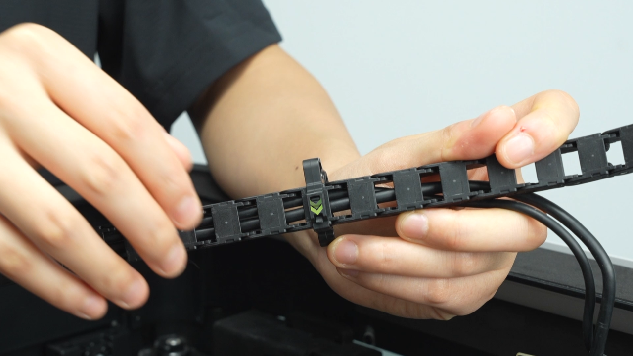
After inserting the USB-C cable and toolhead to MC board cable into the cable chain bracket, insert the two cables into the cable chain with the hollow structure facing forward, starting from the end with the bumps on the top and bottom.
 |
 |
The thin cable is on the inside and the thick cable is on the outside, that is, the thick cable (MC-TH) presses the thin cable (USB-C) into the two cables.
Pull the two cables backwards to keep the two cables in the toolhead cable chain in a state of neither loose nor tight, and clip the cable chain into the cable chain bracket.
 |
 |
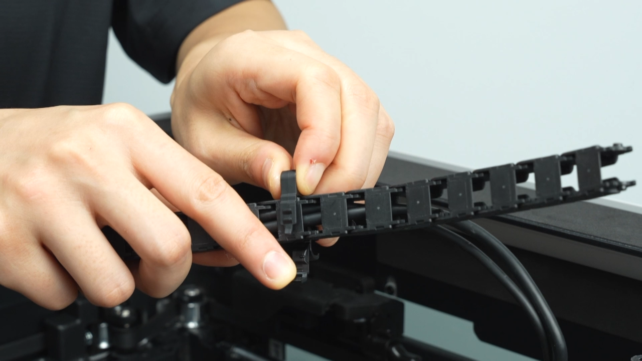
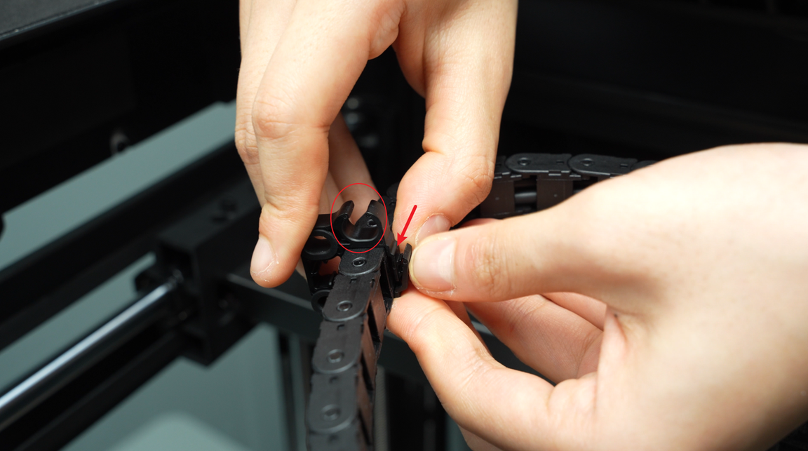
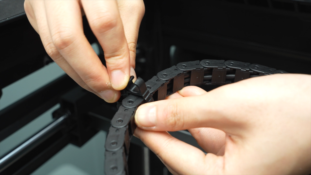
Clip the first clip into the top of the 8th cable chain. When installing the clip, pay attention to the notched groove on the top.
 |
 |
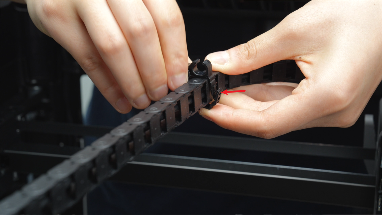 |
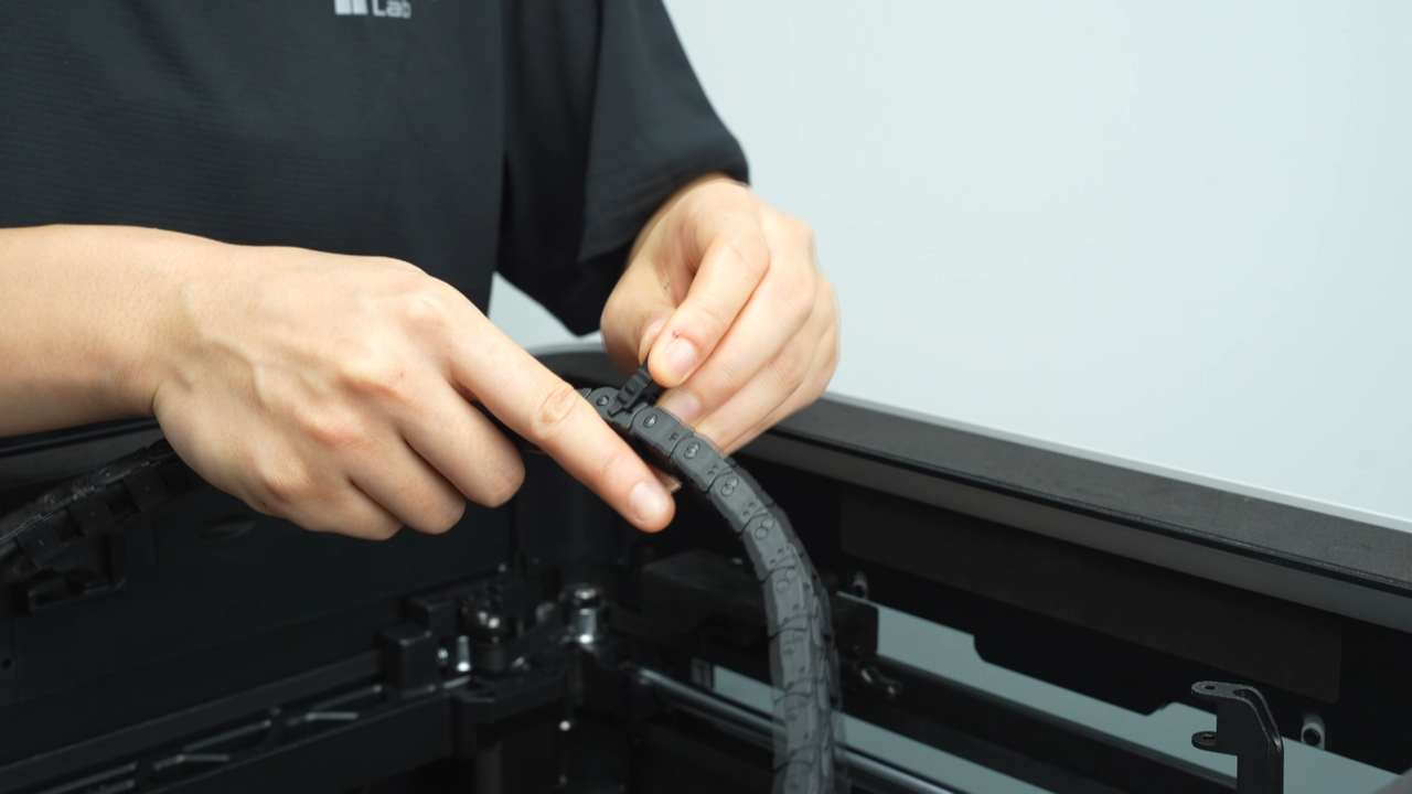
Then clip the second clip 10 sections back from the first clip (the section where the first clip is located does not count).
 |
 |
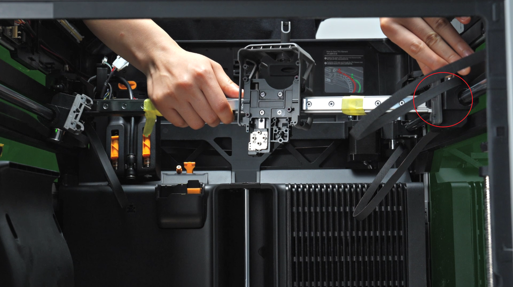
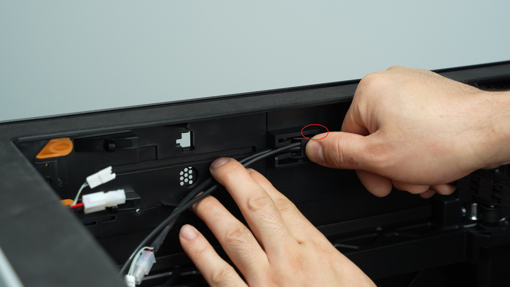
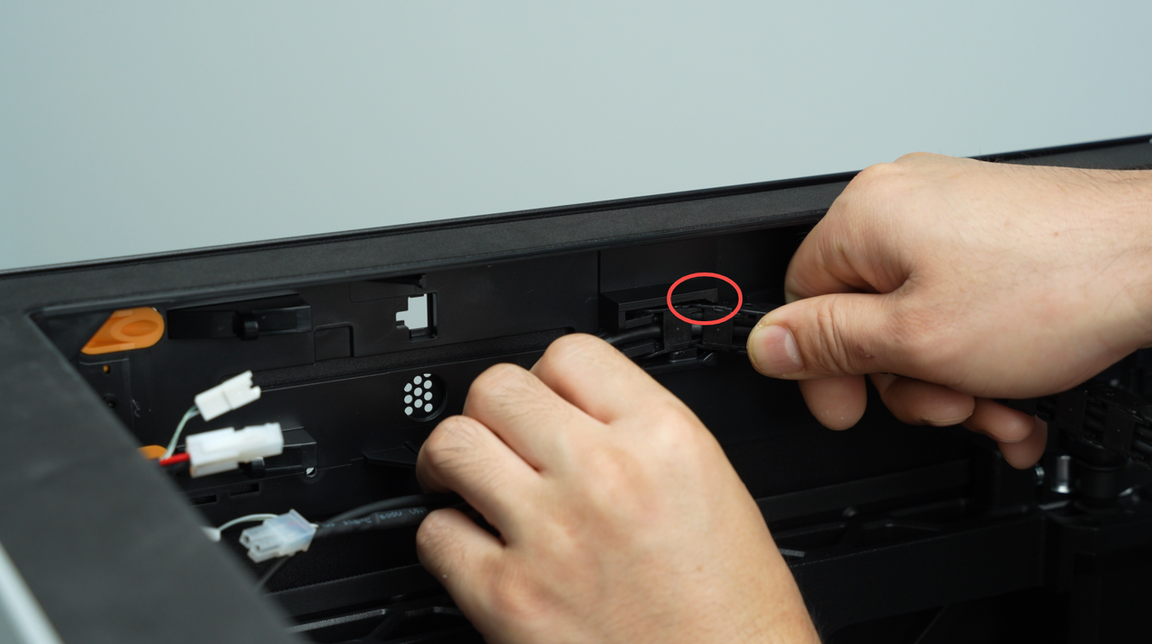
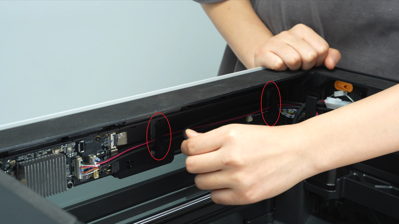
When installing the cable chain, tilt it to the lower left, avoid the platform in the upper right corner, install the other end of the cable chain on the upper cover frame, and then tilt and press it in at the circle. After it is installed in place, you can pull the cable chain left and right to see if it comes out, and check whether the upper and lower ends of the cable chain are level, and whether the top frame and the end of the cable chain are engaged together.
 |
 |
 |
 |
¶ Step 10 - Install the AP board cover, filament buffer, USB-C cable, and toolhead to MC board cable
Arrange the USB-C cable and toolhead to MC board cable along the cable slot, then reinstall the buffer, press the buffer with one hand to prevent it from falling, and tighten the four screws of the buffer with the other hand.
 |
 |
 |
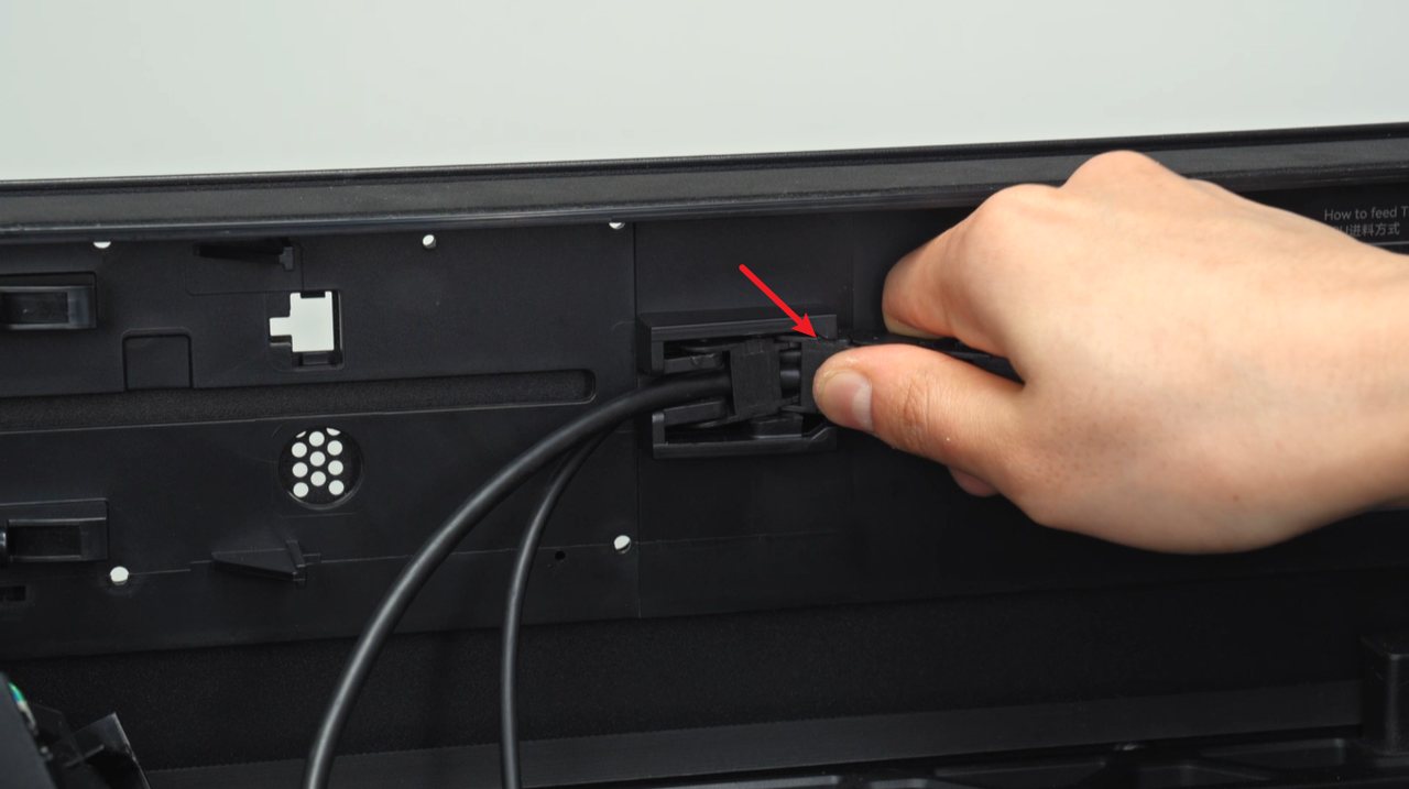
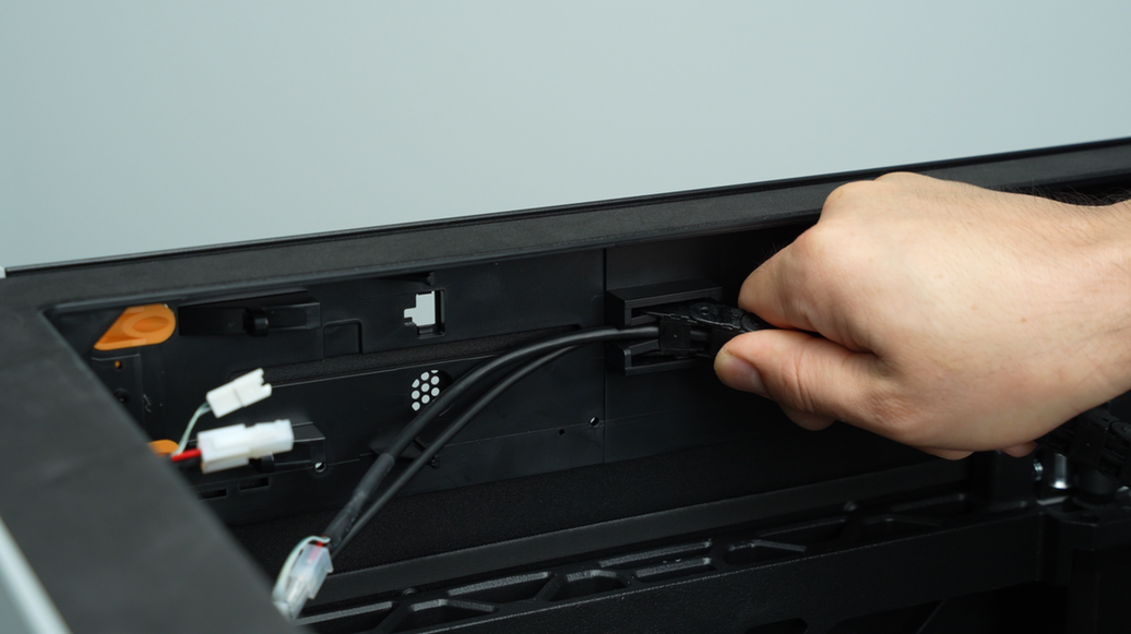
After connecting the two branch plugs of the toolhead to MC board cable in sequence, clip the toolhead to MC board cable and USB-C cable into the cable clip and close the clip.
 |
 |
Insert the USB-C cable into the cable clip on the side and insert the plug into the AP board. The letter A must face forward and push the USB-C until it stops.
 |
 |
Arrange the cables, especially the tube inlet and outlet near the buffer should not be blocked by the 2 branch plugs of toolhead to MC board cable. It is recommended to hide the small plug behind the large plug.
Install the AP cable cover, first insert the back half, then the front half, press it into place, align it with the screw hole, and lock in 1 screw.
 |
 |
 |
 |
¶ Step 11 - Connect the plug on the TH board and install the nozzle camera
First, insert the lifting motor Hall cable into the small cable slot, and then insert the right eddy sensor and left eddy sensor cables into the small cable slot in turn. Insert the lifting motor Hall cable into the plug, make sure the head of the FPC cable is completely inserted into the plug (the white line is in a horizontal state, indicating that the FPC cable is inserted in place), and then snap the socket.
Then replace the right eddy sensor plug with the metal side facing up, align the interface, and press down into the plug; replace the left eddy current coil plug in the same way, fold the excess wire length, and stick the acetate tape back on the left and right nozzle eddy sensor plugs.
 |
 |
 |
 |
Insert the toolhead camera plug. After it is fully installed, remember to use the adhesive on the back of the cable to stick the cable to the hotend fan bracket.
 |
 |
Screw in the two fixing screws of the nozzle camera, insert the nozzle camera plug, and after it is fully installed, use the adhesive on the back of the cable to stick the cable to the motor cover.
 |
 |
The plugs and cables of the nozzle camera, toolhead camera and lifting motor are similar to each other. Here, you only need to insert the plugs of the two cameras, and the lifting motor is inserted into the subsequent extruder connection board. When inserting the plugs, please do not make the wrong parts to avoid power-on abnormalities or even permanent damage.
Finally, insert the extruder Hall cable plug and the extruder servo motor cable plug in turn. It is also necessary to ensure that the white wires at the cable heads are in a parallel state. The extruder servo motor cable is located below the switching motor cable and is shorter.
 |
 |
¶ Step 12 - Install the TH connection board and connect the plug on it
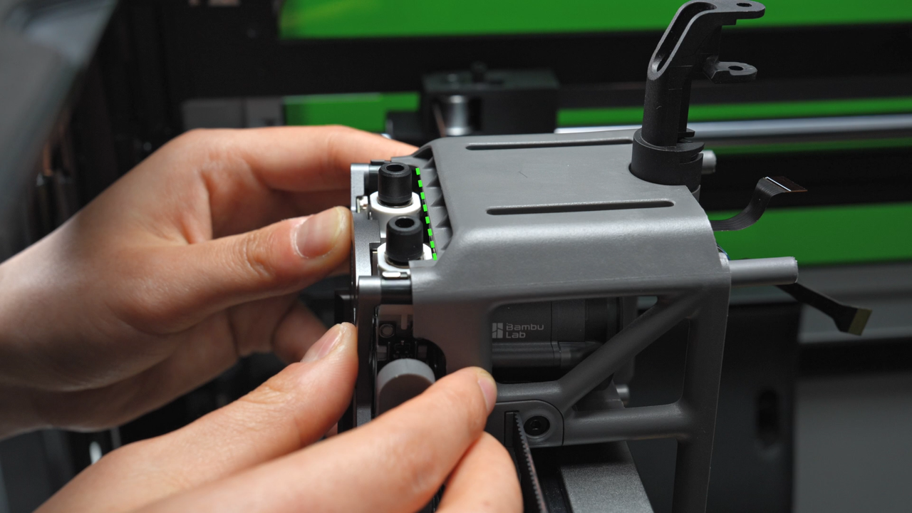
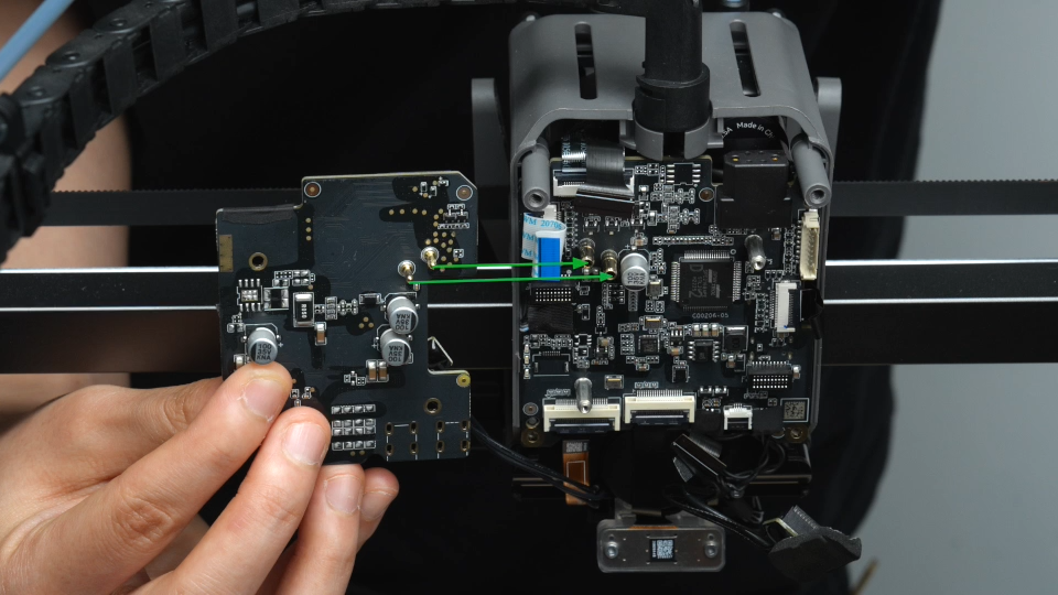
There are two metal posts on the back of the extruder connection board. Align them with the metal holes on the TH board and insert them. Push back while gently shaking to ensure that the extruder connection board is installed in place.
 |
 |
Then tighten the two retaining screws on the extruder connection board.
 |
 |
Insert the side toolhead sensor FPC cable into the gap between the TH board and the extruder connection board, and then reconnect the lifting motor connector, the left hotend heating assembly plug, the right hotend heating assembly plug, the TH board connector, and the switching motor connection line in turn.
When connecting the lifting motor, TH board, and switching motor cables, make sure that the head of the FPC cable is completely inserted into the plug (the plugs of these three FPCs all have a horizontal line, and the horizontal line is horizontal to indicate that the FPC cable is inserted in place), and then snap the socket. Finally, gently fold the FPC cable with your fingers.
 |
 |
 |
 |
When connecting the left and right hotend heating assembly plugs, you need to plan the wiring reasonably. Pass the left hotend heating assembly cable through the cable slots at the bottom and back in turn to prevent the cable from loosening.
 |
 |
Then insert the left hotend heating assembly plug into the corresponding interface of the TH board, and then re-tighten the foam.
 |
 |
When connecting the right hotend heating assembly, first pass the right hotend heating assembly cable through the cable slot on the back, and then insert the plug into the TH board.
 |
 |
¶ Step 13 - Install the part cooling fan
With the metal side facing up, align the connector, press down the part cooling fan plug, and put the acetate tape back on.
 |
 |
|
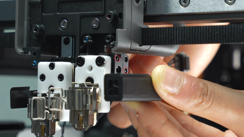
Align the screw holes, cover the part cooling fan, and screw in the 4 fixing screws. (BT3x20 square mark, BT2.6x8 circle mark)
 |
 |
 |
¶ Step 14 - Install the part cooling fan air duct
The left hotend heating assembly cable needs to be installed in the cable slot. Before installing the air duct, press the heating assembly cable into the cable slot to prevent the air duct from pressing the cable.
 |
 |
Install the front 1/4 of the air duct first, so that the back half of the air duct can be tilted more easily to avoid interference from the nozzle camera. Then grab the back half of the air duct and push it upward.
 |
 |
After pushing it in, bend the two sides of the air duct outwards, clamp the two sides of the air duct on the toolhead, and then clamp the air duct upwards with force.
 |
 |
 |
Next, push the top of the front air duct forward to make it fit completely without leaving any gaps.
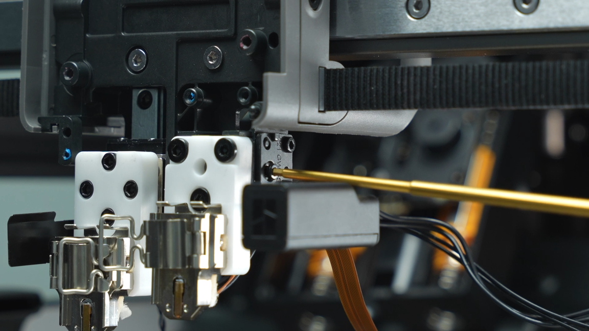
Use an H2.0 Allen key to tighten the four fixing screws (BT3x8).
 |
 |
 |
¶ Step 15 - Install the PTFE tubes in the chamber and on the back of the chamber
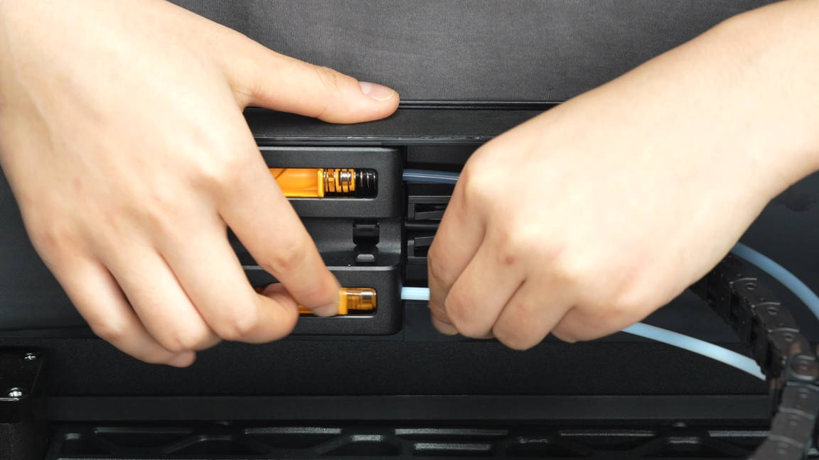
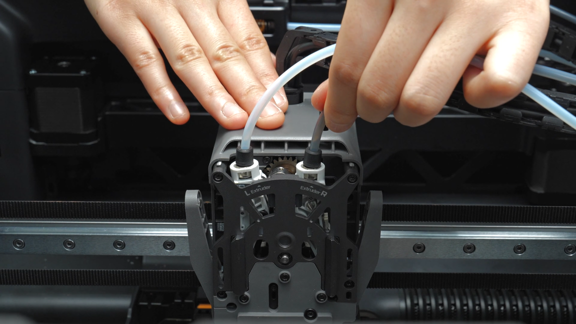
Put the two PTFE tubes through the holes on the side of the cable chain buckle and insert them into the two pneumatic connectors on one side of the buffer. Then insert the other end of the PTFE tube into the two pneumatic connectors above the extruder.
Please note that the PTFE tube above the cable chain needs to be connected to the right extruder, and the PTFE tube below the cable chain needs to be connected to the left extruder.
 |
 |
 |
 |
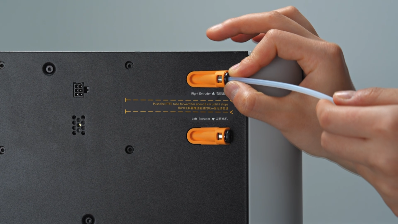
Finally, insert the PTFE tube on the back of the chamber into the coupler. When the PTFE tube can be seen in the small hole in front of the buffer, it means the connection is in place.
 |
 |
¶ Step 16 - Install the left and right hotends and silicone socks for hotend
As with the disassembly operation, if you need to install a hotend and the flow blocker is blocking the hotend, you need to move the flow blocker connecting rod to remove the flow blocker before installing it to prevent the flow blocker from being accidentally bent when installing the hotend. When moving, the flow blocker may not be moved into place at once due to the tilt limit of the connecting rod. You need to move the connecting rod again to ensure that the magnet at the end of the connecting rod is attached to the magnet bracket to ensure that the flow blocker is fully in place.
Install the right nozzle, lock the nozzle buckle and put on the silicone sock for hotend.
 |
 |
Move the flow blocker connecting rod to move the flow blocker to the other side, and then install the left nozzle. Tighten the nozzle clip and put on the silicone sock for hotend.
Please note that when installing the left silicone sock for hotend, it is necessary to ensure that the silicone sock for hotend cannot be tilted to avoid deformation of the windshield next to it.
 |
 |
 |
When replacing the toolhead front cover, you can first snap it into place under the extruder, then push it back to install the front cover in place.
¶ Verify the Functionality
Control the switch of the left and right extruders through the screen, observe whether the extruder switches normally, whether the hotend rises and falls normally, and whether the flow blocker moves left and right normally. After the test passes, complete a normal loading and unloading for the left and right hotends through the screen.
¶ End Notes
We hope the detailed guide provided has been helpful and informative.
If this guide does not solve your problem, please submit a technical ticket, we will answer your questions and provide assistance.
If you have any suggestions or feedback on this Wiki, please leave a message in the comment area. Thank you for your support and attention!