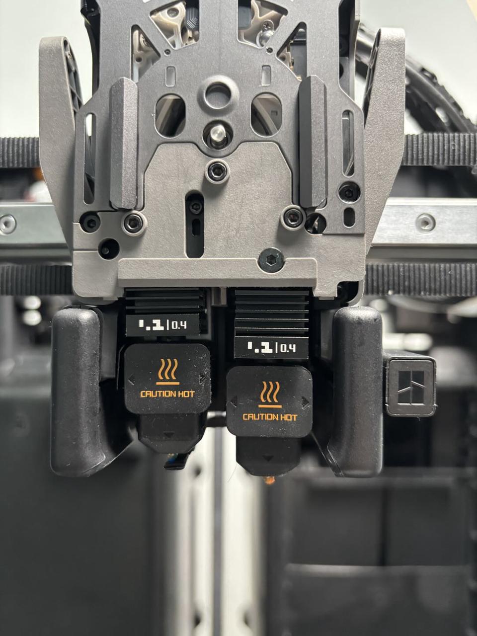
¶ Hotend Heating Assembly
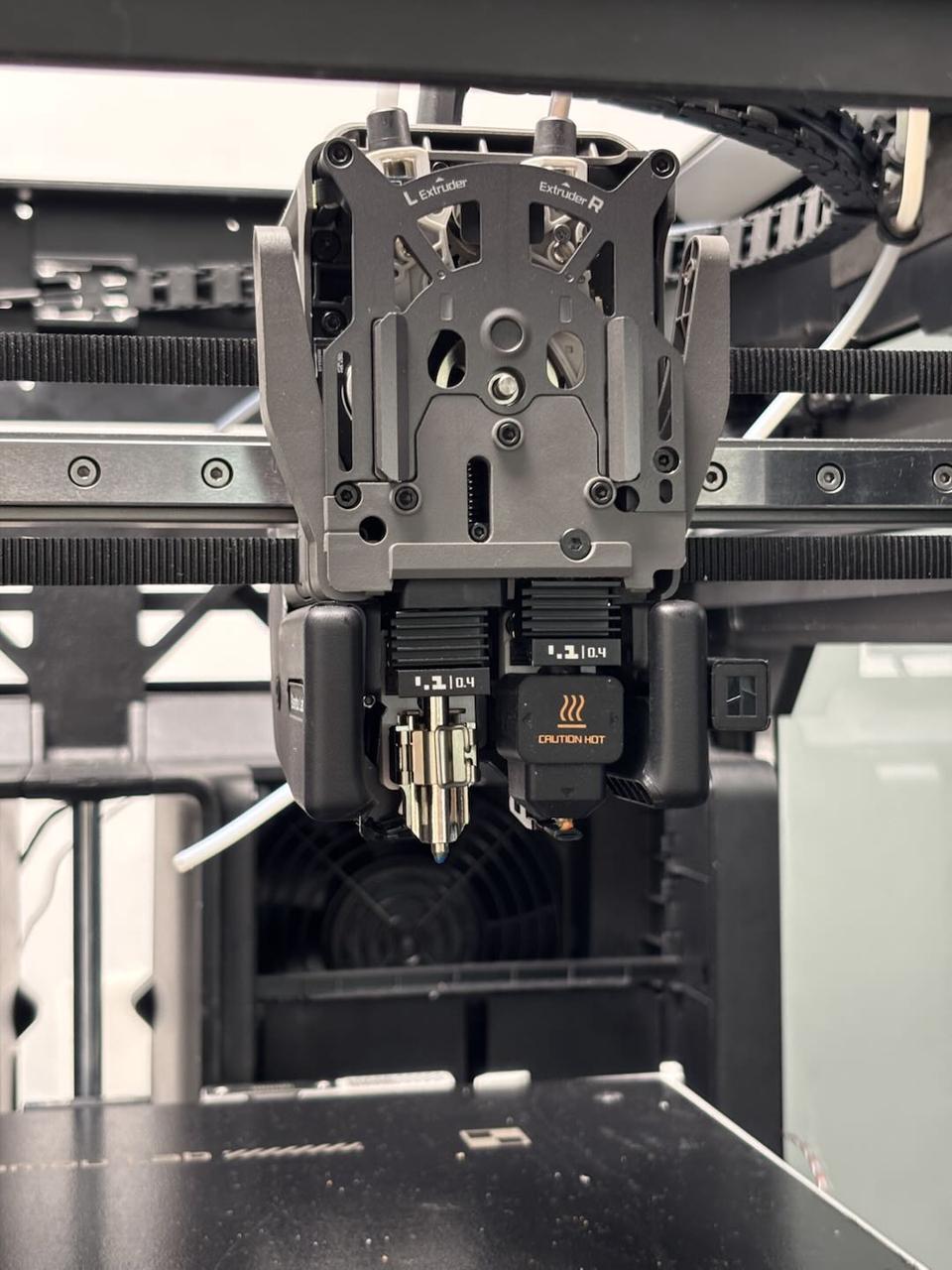
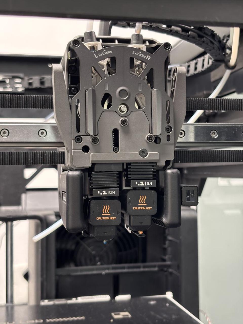
The H2D printer is equipped with two hotend heating assemblies: one for the left hotend and one for the right. These assemblies are not interchangeable. If one is damaged, you must replace it with the corresponding hotend heating assembly. Below are the details of the left and right hotend heating assemblies and their accessories:
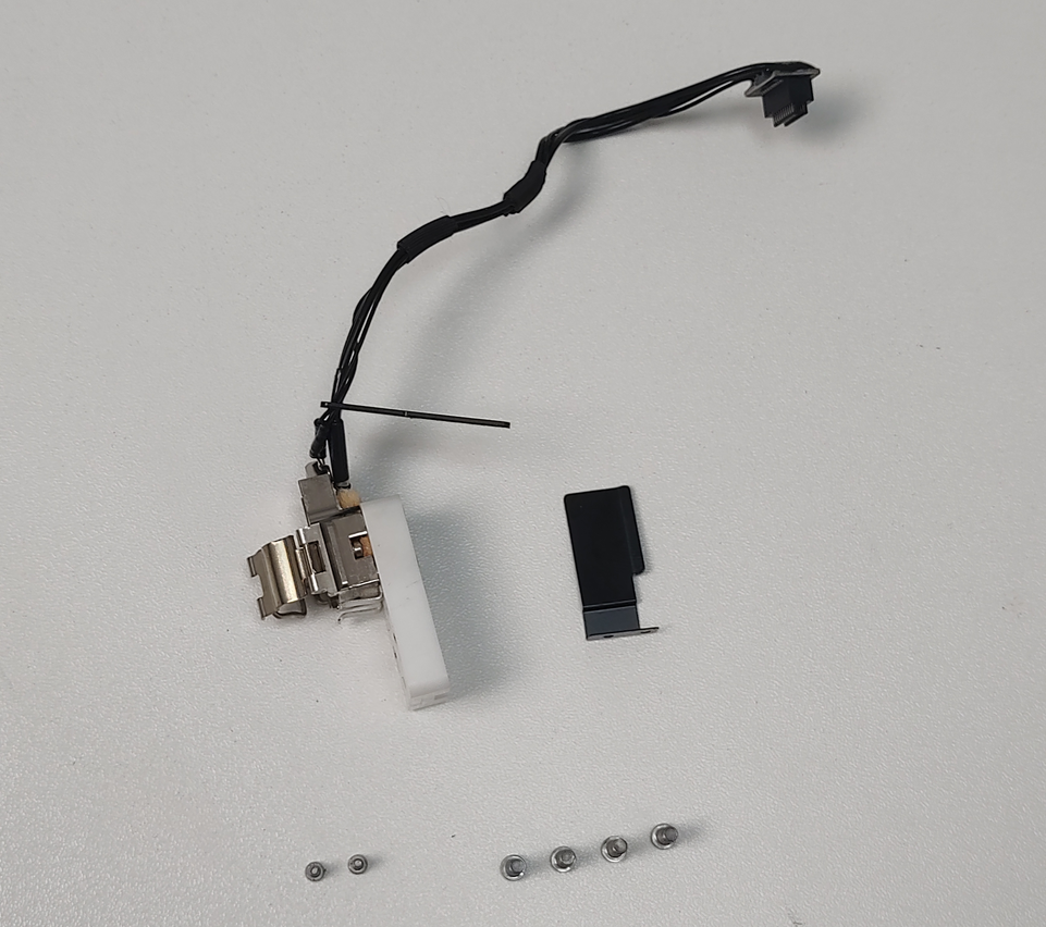
¶ Left Hotend Heating Assembly
- Left hotend heating assembly (pre-installed with cable sheet) × 1
- Wind blocker × 1
- M1.6×4 screws (for securing the cable sheet and wind blocker) × 2
- M2.5×7 screws (for securing the left hotend heating assembly) × 4
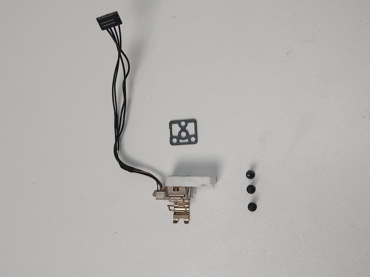
¶ Right Hotend Heating Assembly
- Right hotend heating assembly × 1
- Insulating sheet × 1
- M3×10 screws × 3
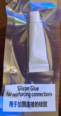
Note: Some batches of spare parts include a tube of white electronic silicone. This silicone is not required for the replacement process outlined in this guide and can be discarded or retained for other uses.
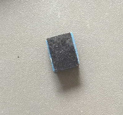
Note: Some batches of spare parts include a new foam, which has the same function as the existing one, with only a different appearance.
If the original foam is not damaged during removal, it can be reused.
If the original foam is damaged during removal, please replace it with the new one.
Important: Use only H2D-specific hotend heating assemblies. H2D and A1 series hotend heating assemblies are not compatible. H2D hotend assemblies are optimized for the H2D printer, ensuring superior compatibility.
¶ When to Replace
- Abnormal hotend heating function
- Inability to secure the hotend with the buckle
¶ Required Tools and Materials
- New hotend heating assembly (left or right, depending on the situation)
- H2.0 Allen key
- H1.5 Allen key
¶ Safety Precautions
Critical Warning:
Before performing any maintenance on the printer or its electronic components (including toolhead cables), turn off the printer and disconnect the power supply to prevent short circuits, which could cause additional electronic damage or safety hazards.
During maintenance or troubleshooting, ensure the hotend and print bed are at a safe temperature. If operation at high temperatures is necessary, wear heat-resistant gloves to ensure safe and effective maintenance.
For any questions about this guide, please contact online technical support (available 9:00–21:00). We will respond promptly and provide the assistance you need.
¶ Replacing the Left Hotend Heating Assembly
¶ Removing the Left Hotend Heating Assembly
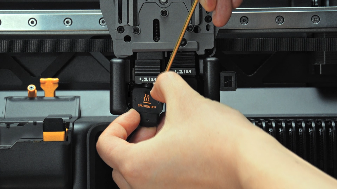
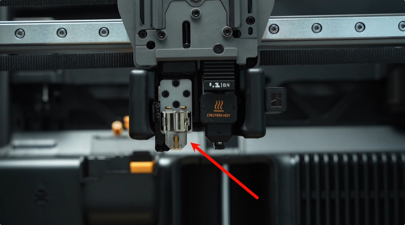
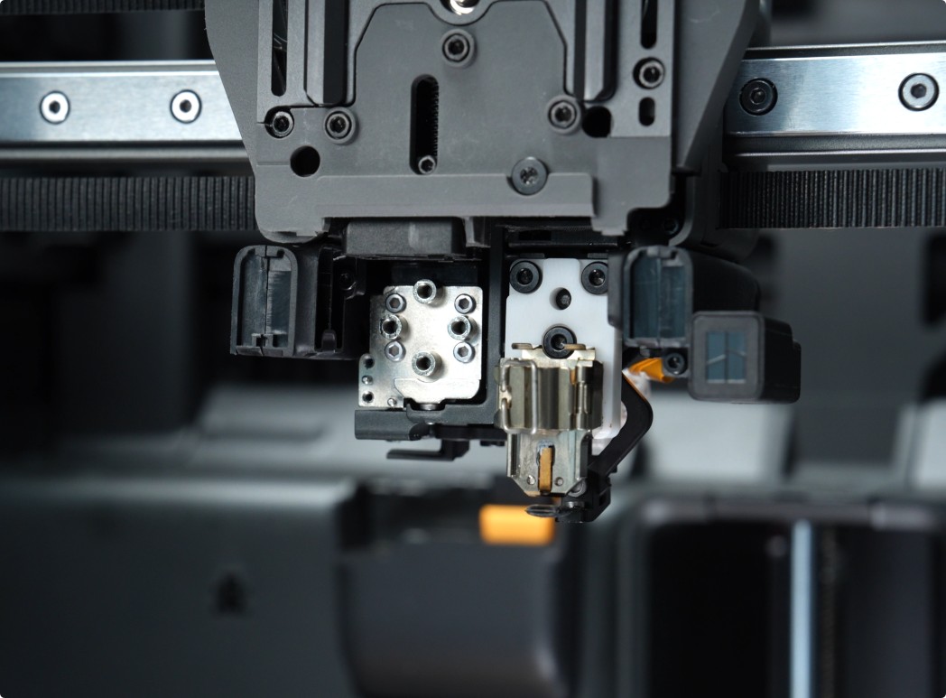
¶ Step 1: Remove the Left Toolhead Hotend
Switch to the left hotend, turn off the printer, and disconnect the power cable. Remove the silicone sleeve and the left hotend.
 |
 |
¶ Step 2: Remove the Part Cooling Fan and Air Duct
Refer to the following video or Wiki for instructions on removing the part cooling fan and air duct:
 |
 |
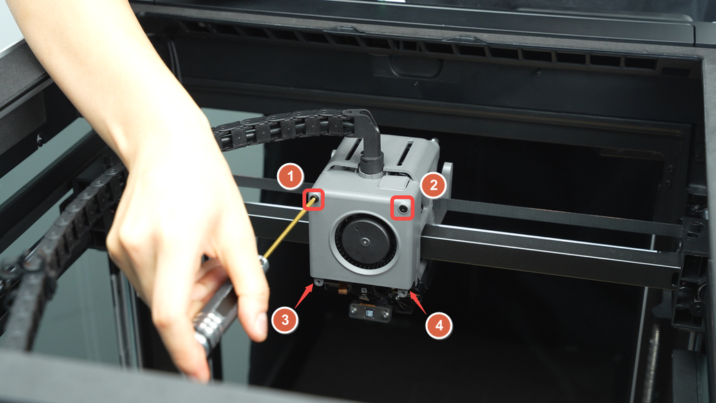
¶ Step 3: Remove the Left Hotend Heating Assembly
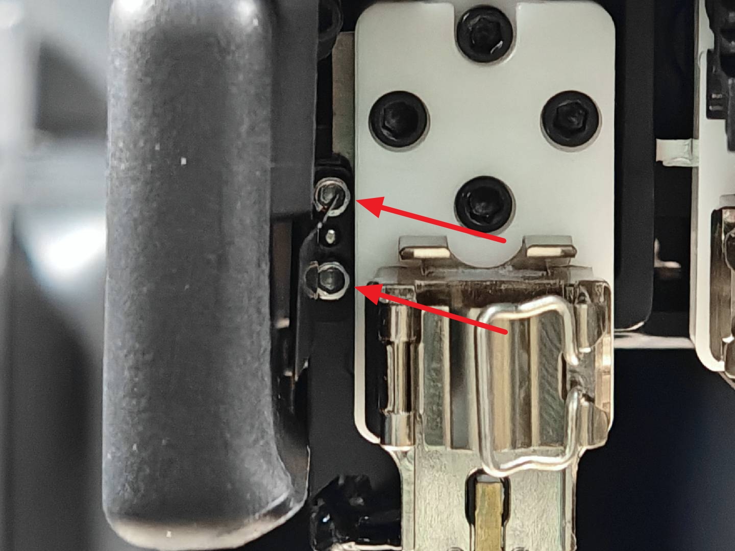
Use an H2.0 Allen key to remove the four hotend fixing screws (M2.5×7).
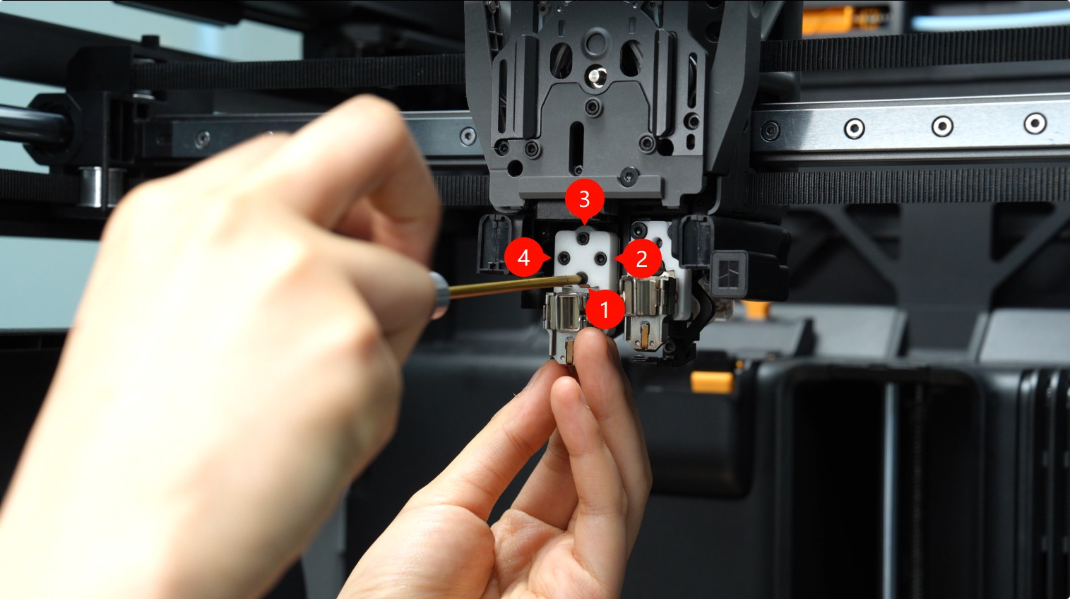
Use an H1.5 Allen key to remove the two cable sheet/wind blocker fixing screws (M1.6×4).
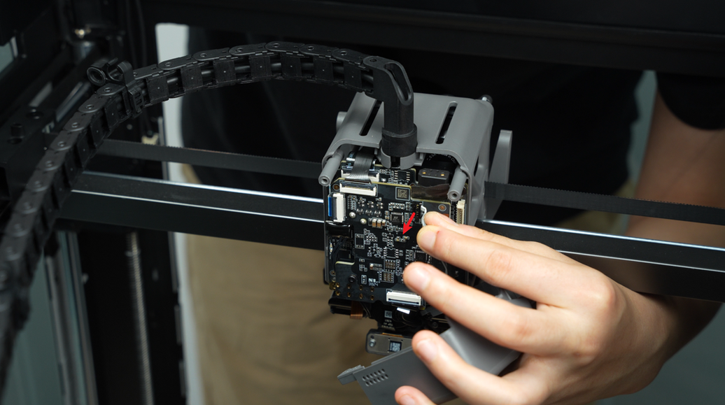
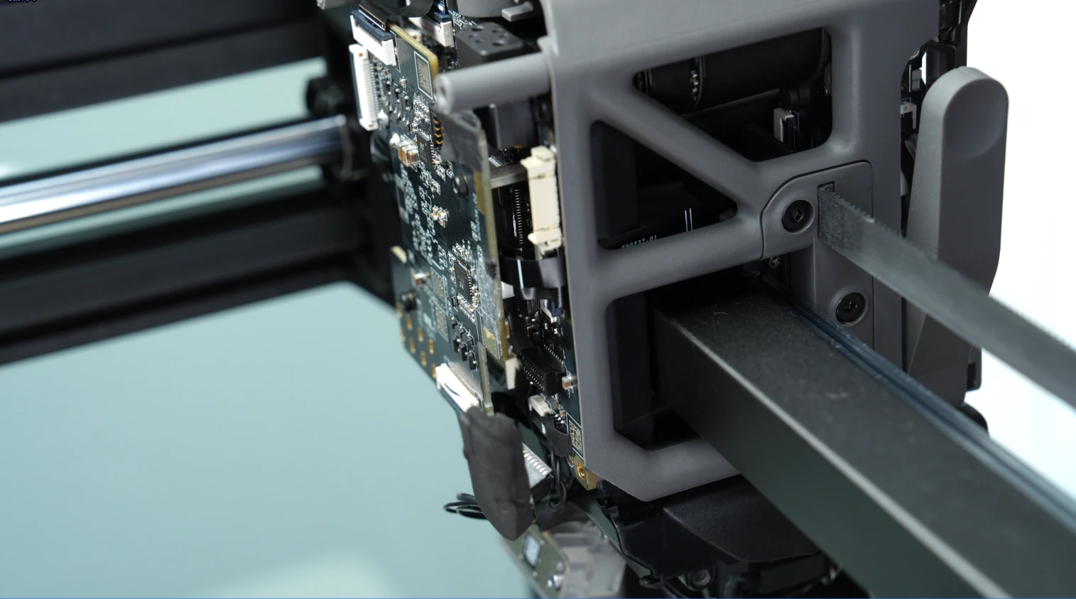
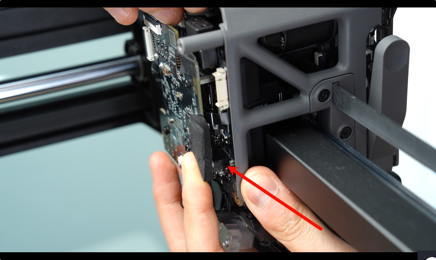
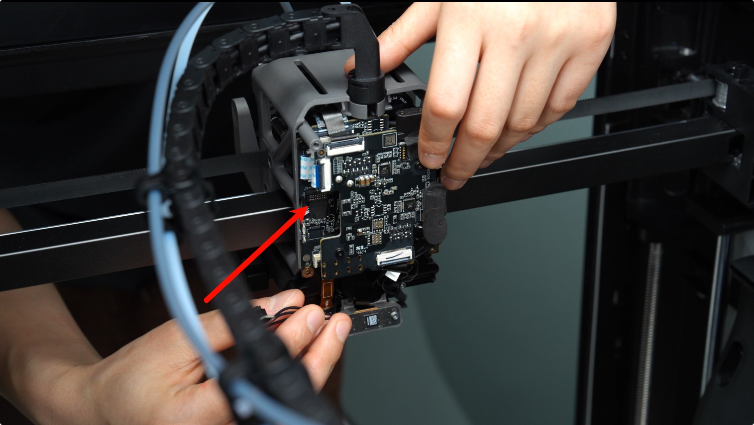
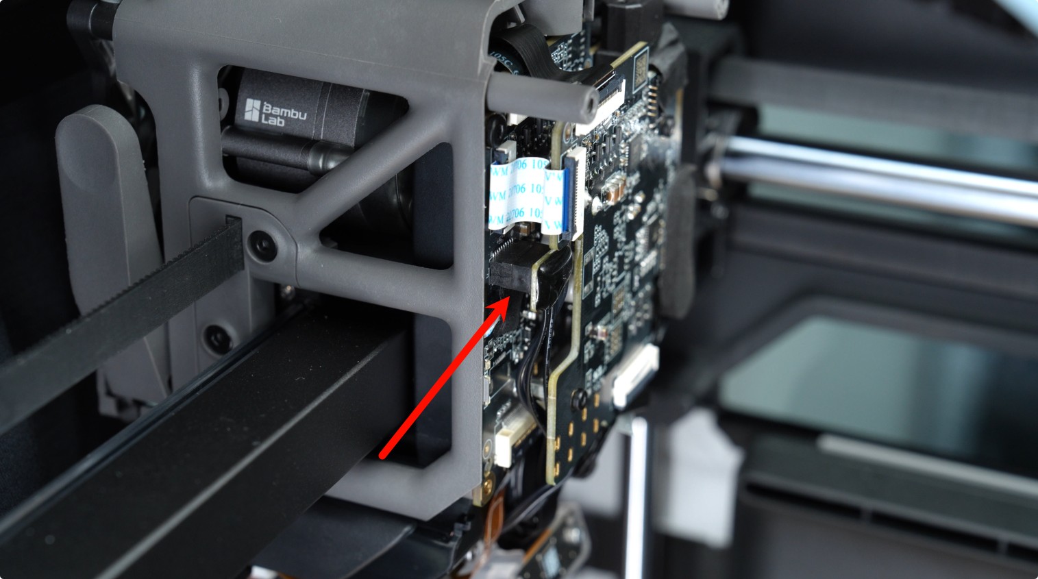
Remove the left hotend heating assembly cable from the cable clip, peel off the foam adhering to the TH board, and disconnect the left hotend heating assembly from the TH board.
Caution: When peeling off the foam, pull from bottom to top to avoid tearing or damaging it.
 |
 |
Once the cable is disconnected, remove the left hotend heating assembly completely.
¶ Installing the Left Hotend Heating Assembly
¶ Step 1: Install the Left Hotend Heating Assembly
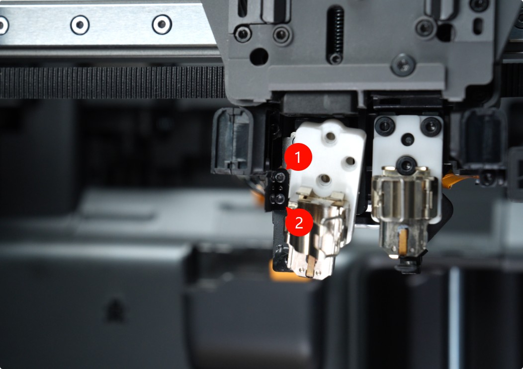
Align the new left hotend heating assembly and cable sheet with the screw holes on the toolhead. Use an H2.0 Allen key to tighten the four fixing screws (M2.5×7).
Confirm the cable sheet position and use an H1.5 Allen key to tighten the two fixing screws (M1.6×4).
Insert the left hotend heating assembly cables into the cable slots, connect the plug to the TH board, and reattach the foam.
|
 |
¶ Step 2: Install the Part Cooling Fan and Air Duct
Refer to the following video or Wiki for instructions on installing the part cooling fan and air duct:
|
|
¶ Step 3: Install the Toolhead Front Cover and Left Hotend
Reinstall the left hotend and toolhead front cover in sequence.
 |
 |
¶ Replacing the Right Hotend Heating Assembly
¶ Removing the Right Hotend Heating Assembly
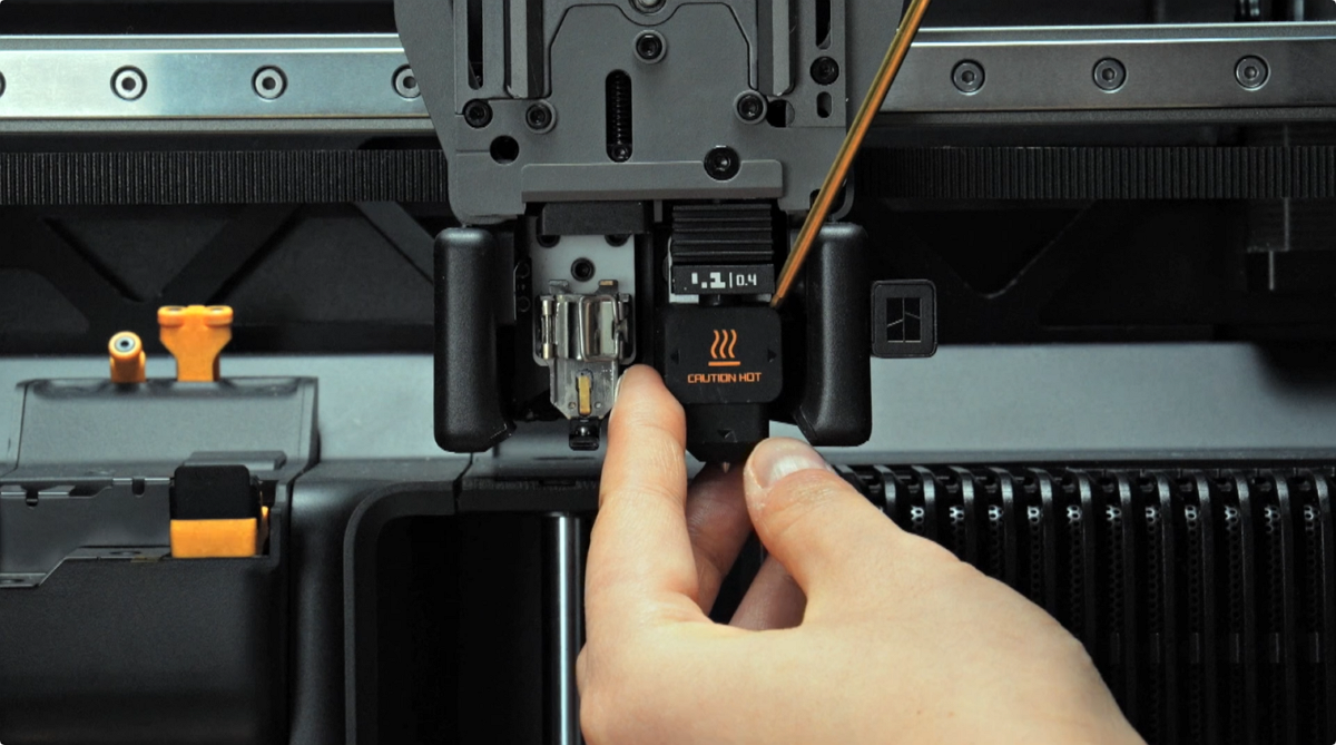
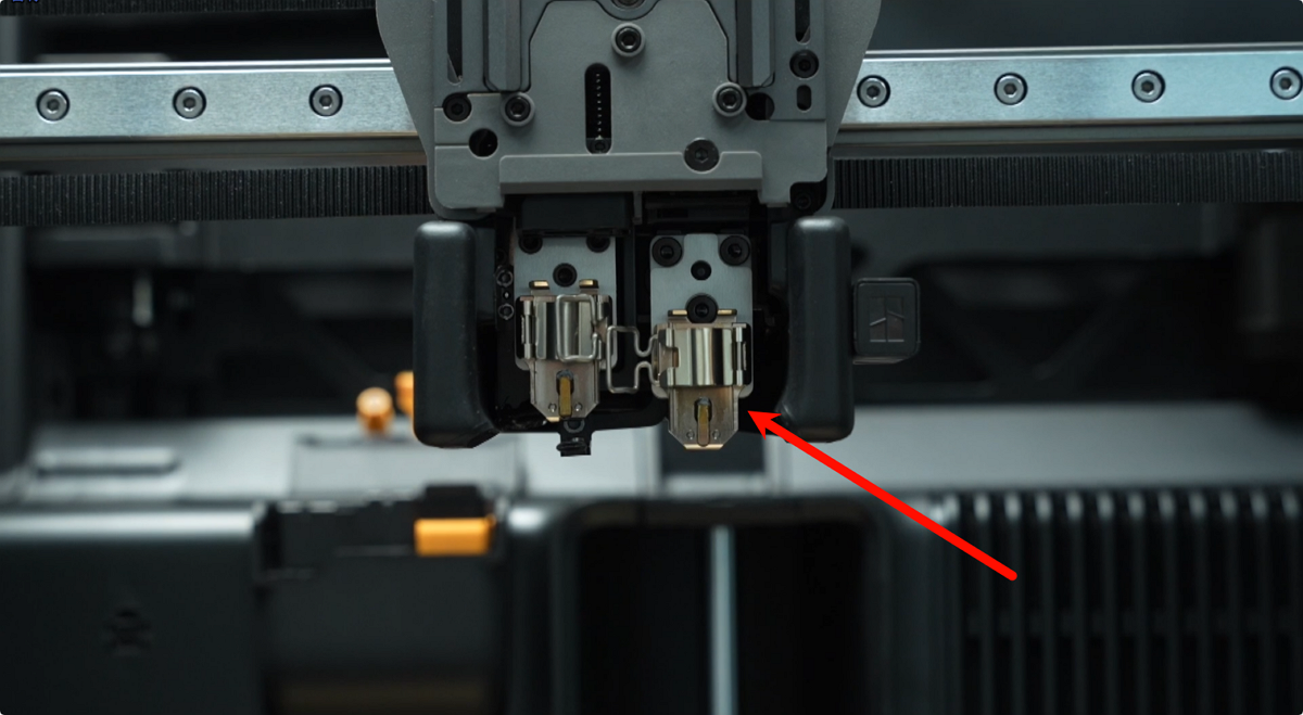
¶ Step 1: Remove the Right Toolhead Hotend
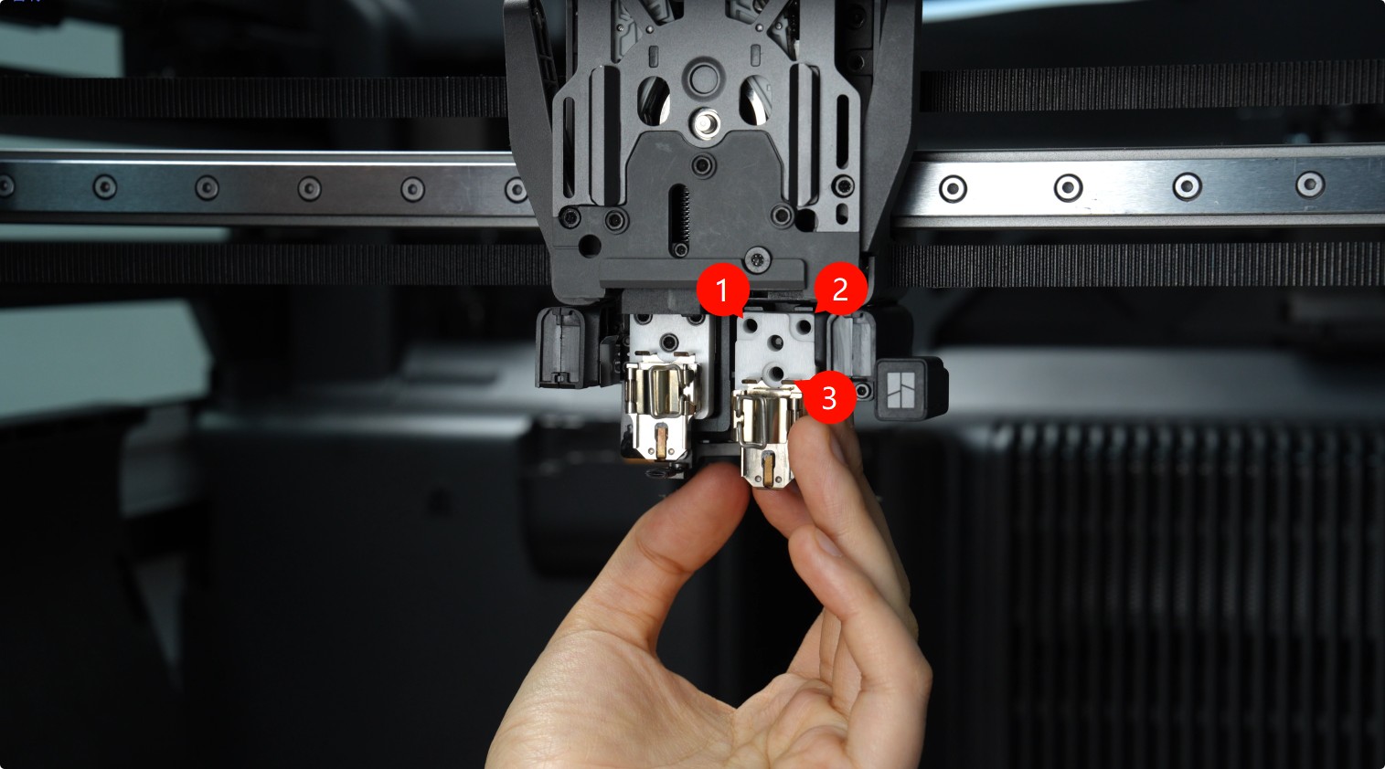
Press the bottom latch to switch to the right hotend.
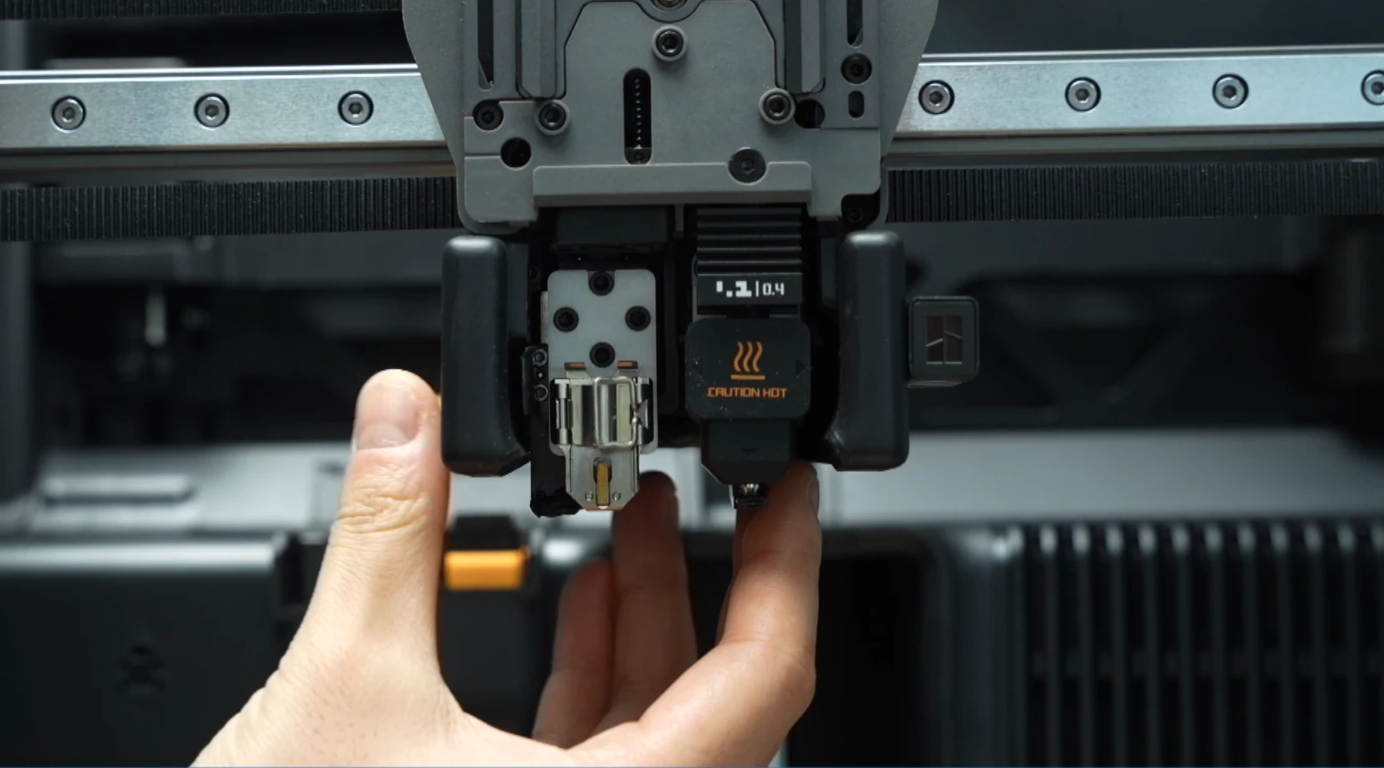
Remove the silicone sleeve and the right hotend in sequence.
 |
 |
¶ Step 2: Remove the Part Cooling Fan and Air Duct
Refer to the following video or Wiki for instructions on removing the part cooling fan and air duct:
|
|
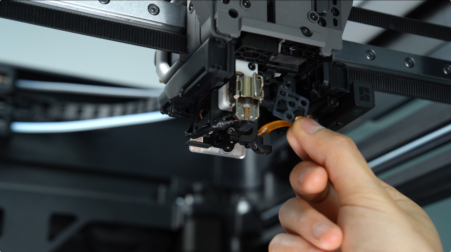
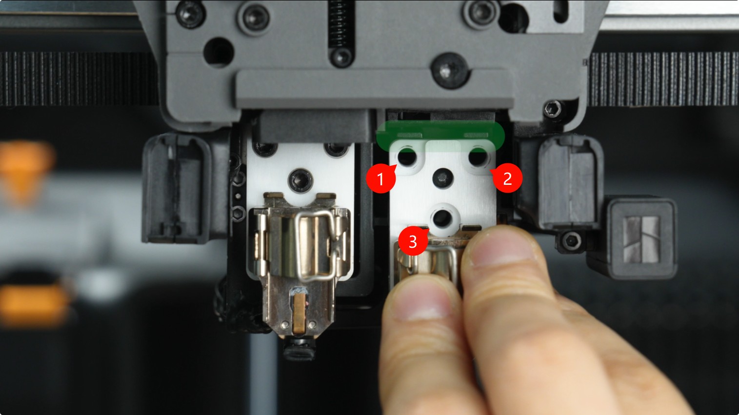
¶ Step 3: Remove the Right Hotend Heating Assembly
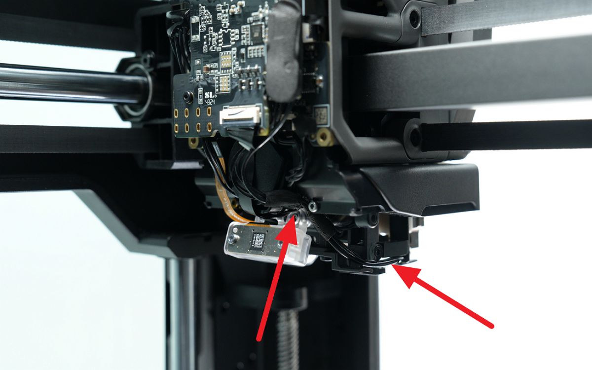
Use an H2.0 Allen key to remove the three right hotend heating assembly fixing screws, then remove the cables from the toolhead camera bracket cable clip.
 |
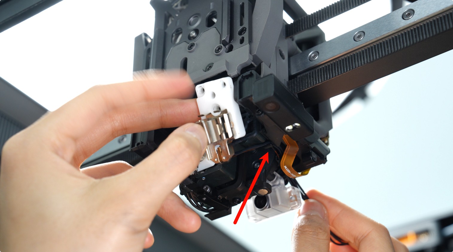 |
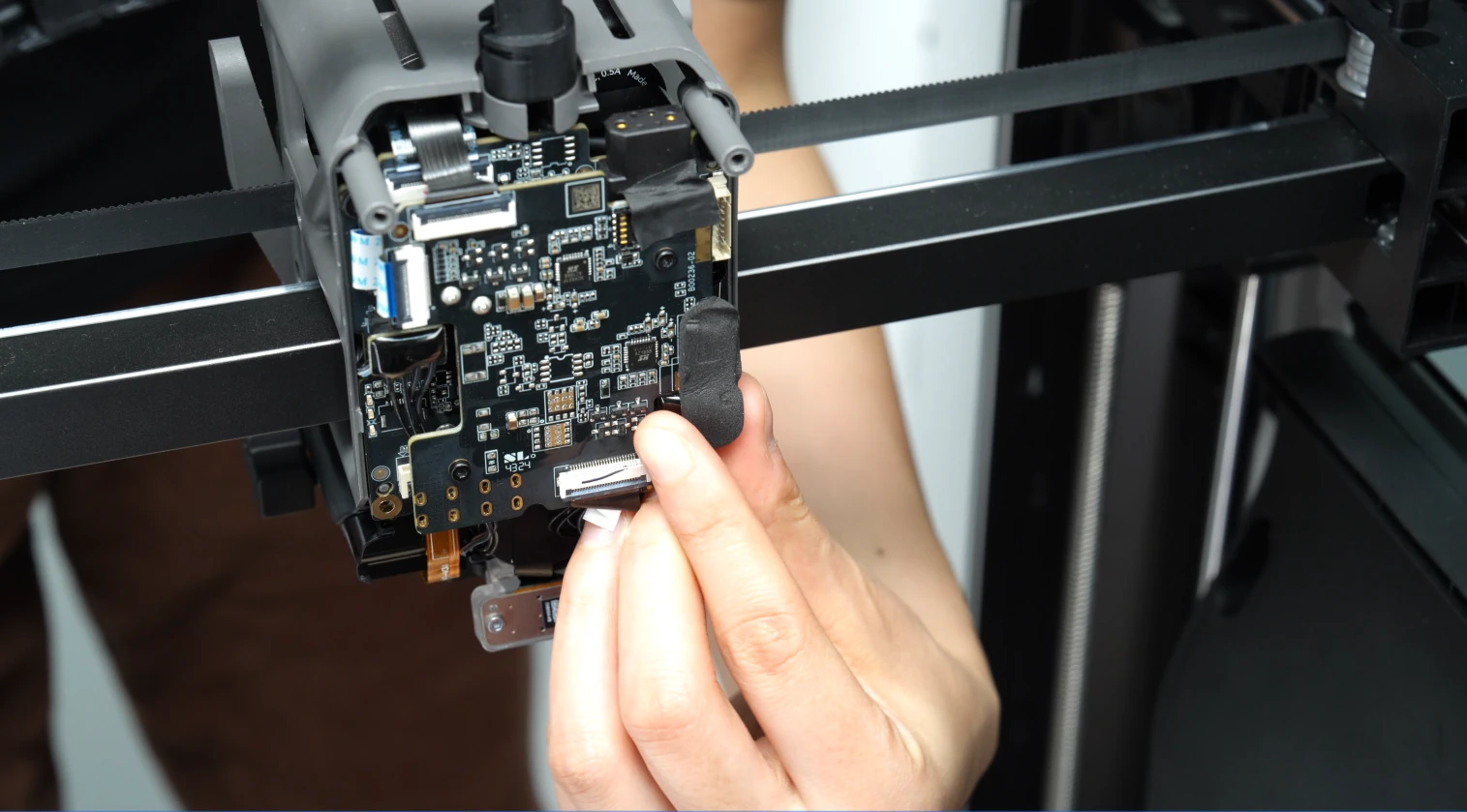
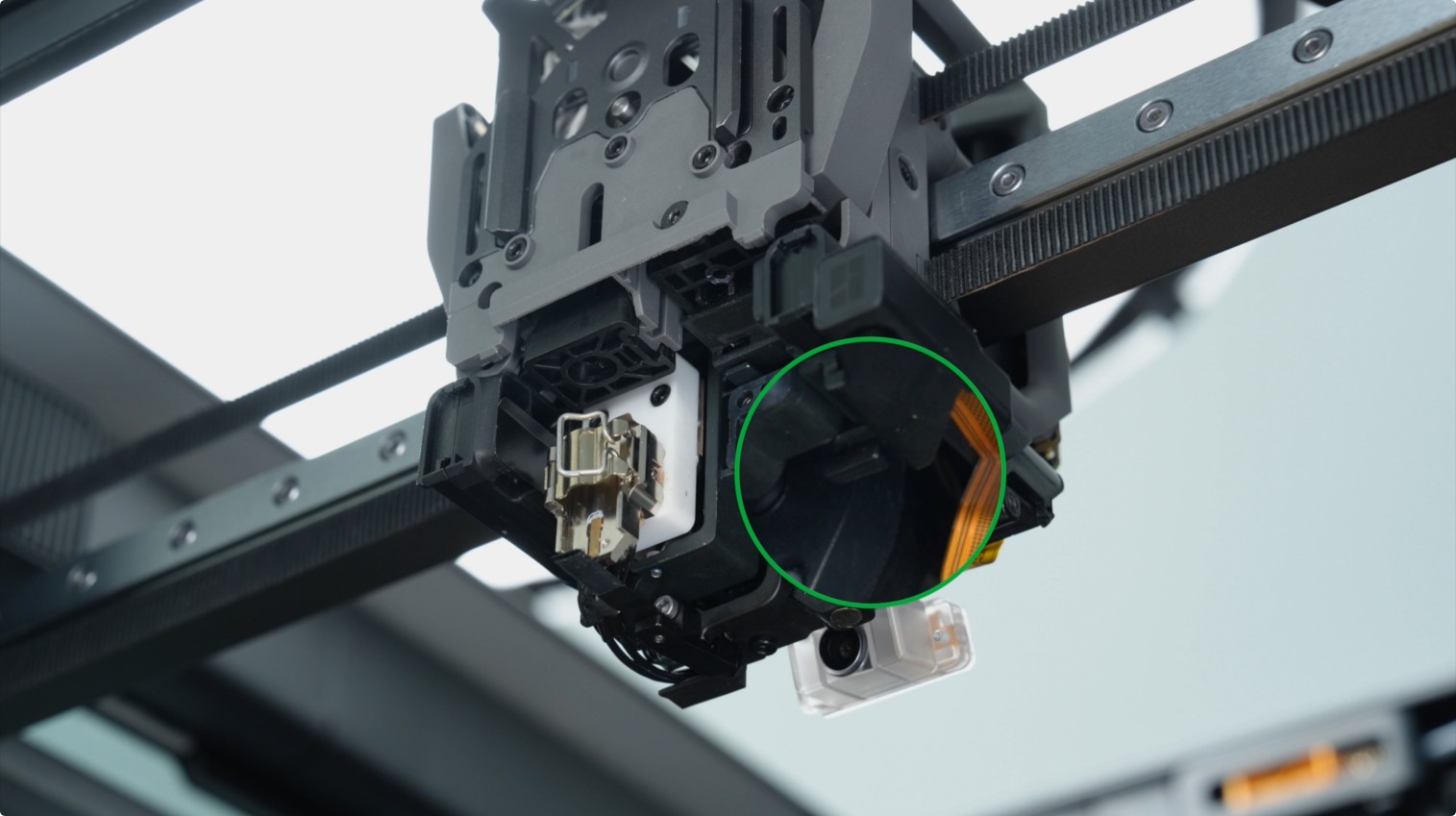
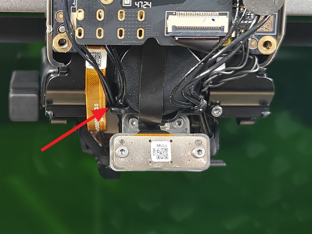
Disconnect the right hotend heating assembly connector from the TH board and remove the insulating sheet.
 |
 |
¶ Installing the Right Hotend Heating Assembly
¶ Step 1: Install the Right Hotend Heating Assembly
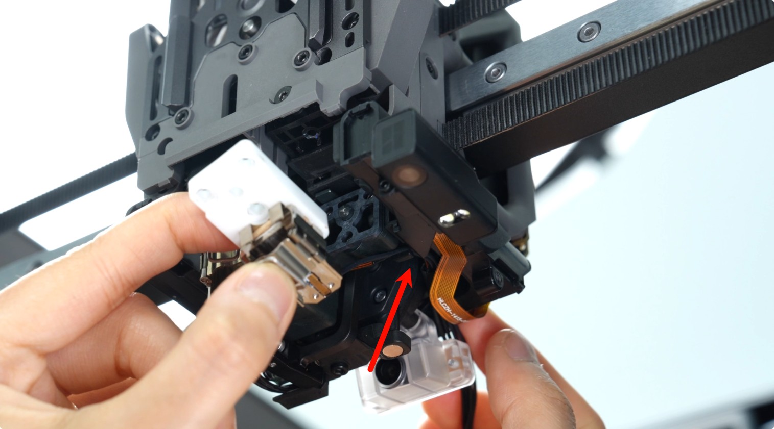
Install the new insulating sheet into the toolhead.

Insert the right hotend heating assembly cables into the cable slots.
 |
 |
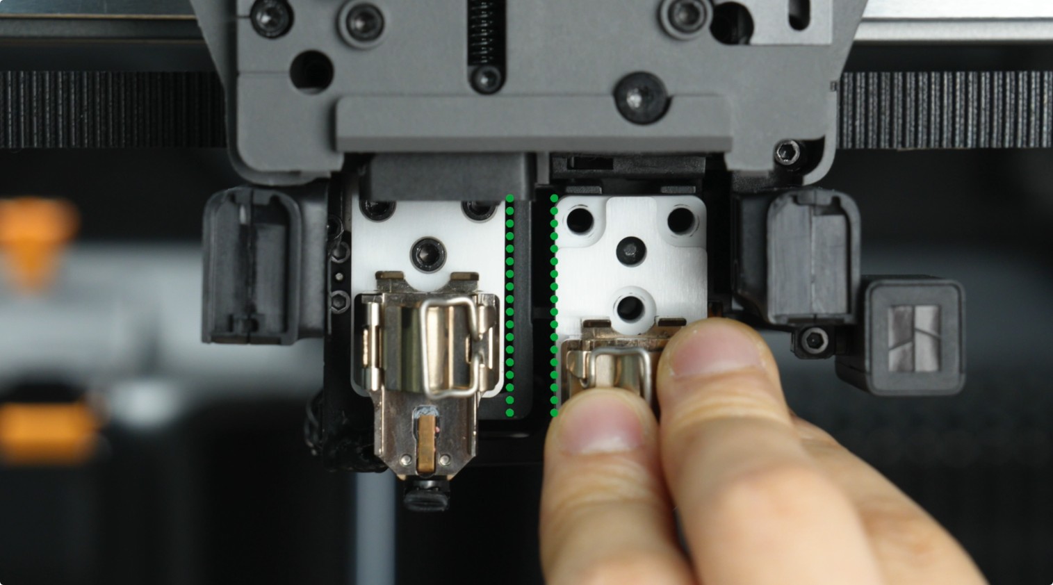
Ensure the left and right hotend heating assemblies are aligned parallel, then use an H2.0 Allen key to tighten the three fixing screws (M3×10).
 |
 |
Insert the right hotend cable into the nozzle camera cable slot.
After securing the fixing screws, connect the right hotend heating assembly cable connector to complete the installation.
¶ Step 2: Install the Part Cooling Fan and Air Duct
Refer to the following video or Wiki for instructions on installing the part cooling fan and air duct:
|
|
¶ Step 3: Install the Toolhead Front Cover and Right Hotend
Reinstall the right hotend and toolhead front cover in sequence.
 |
 |
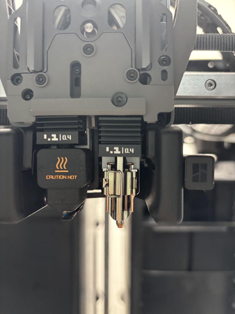
¶ Verifying Successful Replacement
Connect the power and turn on the printer. Set the hotend temperature to 220°C on the screen and check if the hotend heats up properly.
If the hotend heats normally, the replacement is successful. If an error occurs or the hotend fails to heat, verify that the TH board connector is properly connected.
¶ End Notes
We hope the detailed guide provided has been helpful and informative.
If this guide does not solve your problem, please submit a technical ticket, we will answer your questions and provide assistance.
If you have any suggestions or feedback on this Wiki, please leave a message in the comment area. Thank you for your support and attention!