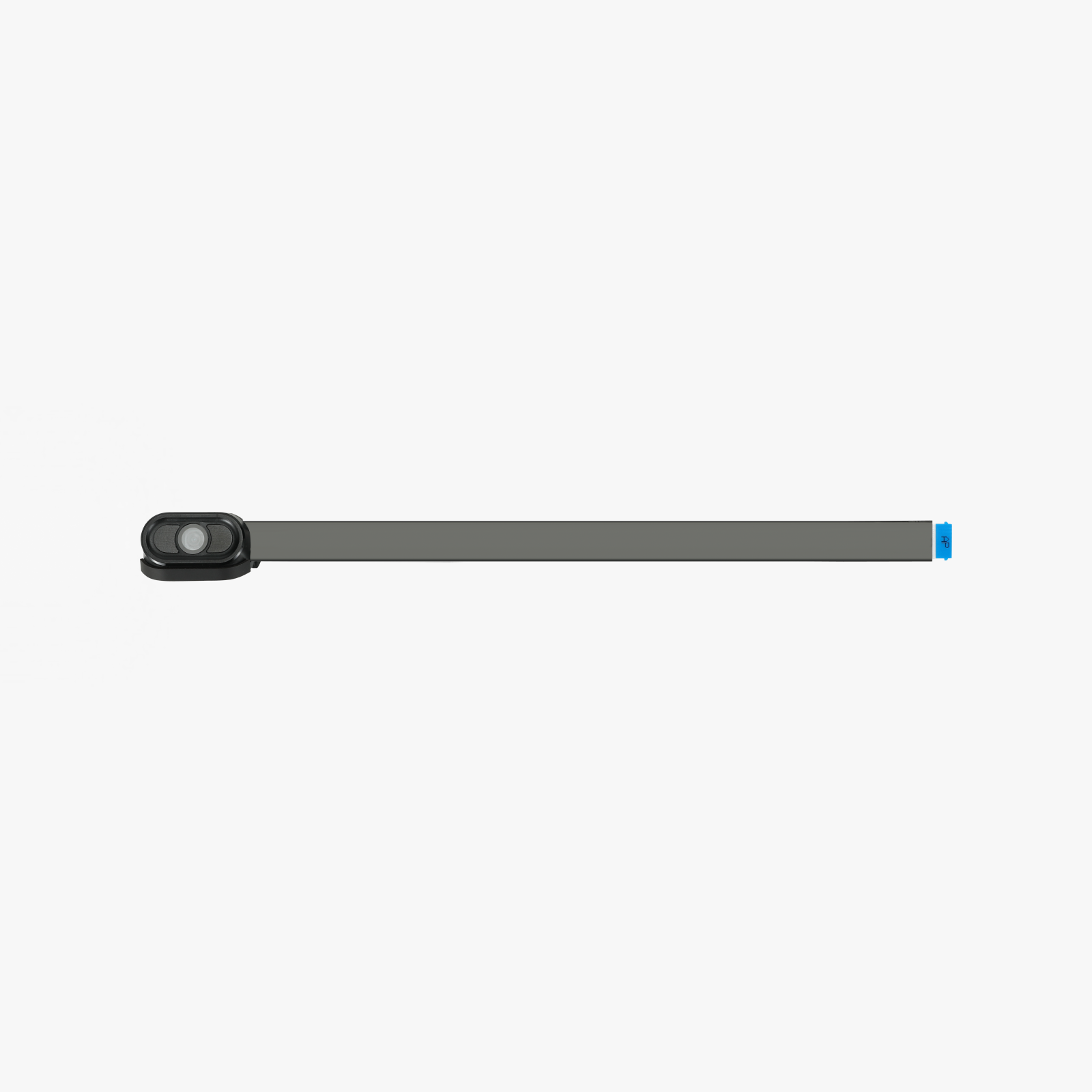
¶ Birds Eye Camera
The BirdsEye Camera is mounted on the inner side of the printer's upper frame. The birdseye camera is only pre-installed in the H2DL, and is not pre-installed in the H2D.
The spare parts of birdseye camera include:
-
BirdsEye Camera × 1
-
BirdsEye Camera Cable × 1
¶ When to use
The birdseye camera is broken.
¶ Tools and Materials Needed
- New birdseye camera
- H1.5 Allen key or tweezers
- H2.0 Allen key - only required when replacing the birdseye camera cable;
¶ Safety Warning
IMPORTANT!
It's crucial to power off the printer before conducting any maintenance work, including work on the printer's electronics and tool head wires. Performing tasks with the printer on can result in a short circuit, leading to electronic damage and safety hazards.
During maintenance or troubleshooting, you may need to disassemble parts, including the hotend. This exposes wires and electrical components that could short circuit if they contact each other, other metal, or electronic components while the printer is still on. This can result in damage to the printer's electronics and additional issues.
Therefore, it's crucial to turn off the printer and disconnect it from the power source before conducting any maintenance. This prevents short circuits or damage to the printer's electronics, ensuring safe and effective maintenance. For any concerns or questions about following this guide, we recommend submitting a technical ticket regarding your issue and we will do our best to respond promptly and provide the assistance you need.
¶ Replace the BirdsEye Camera
¶ Remove the BirdsEye Camera
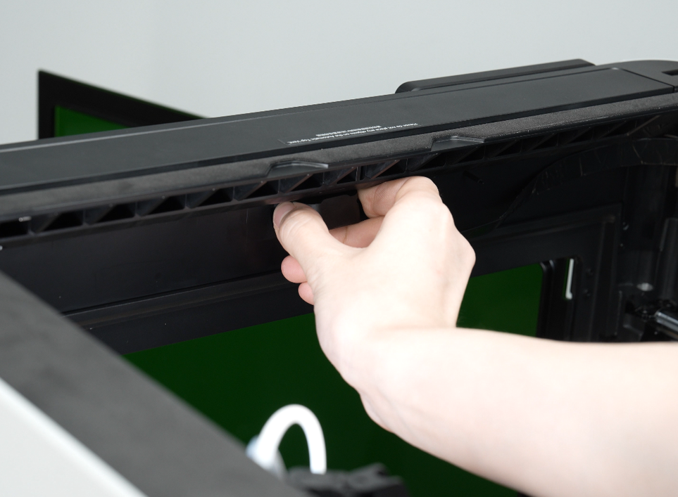
¶ Step 1: Remove the BirdsEye Camera
The birdseye camera is fixed by clips. You can use an H1.5 Allen key or tweezers to pry out the clip on one side of the bird's-eye camera and remove it.
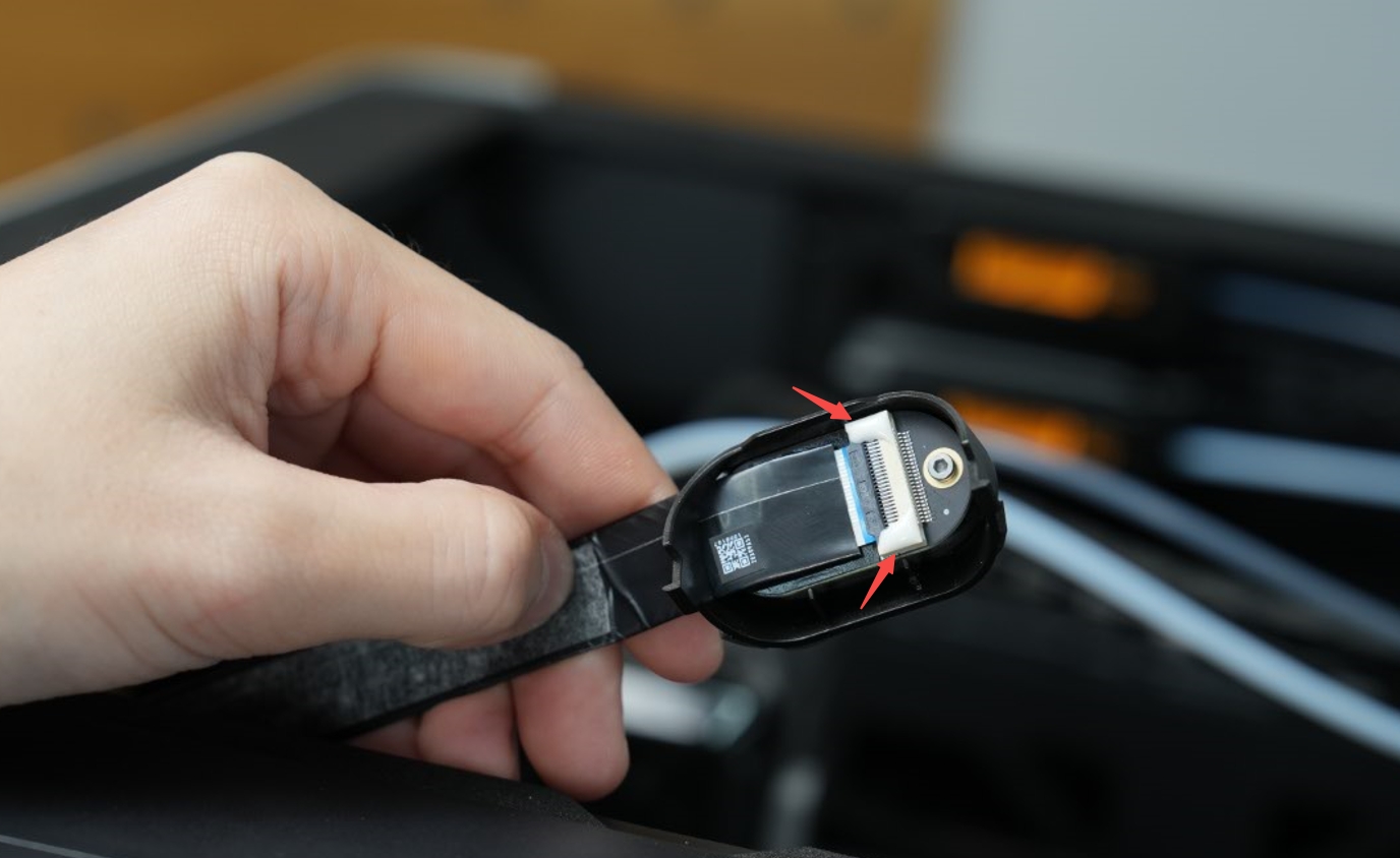
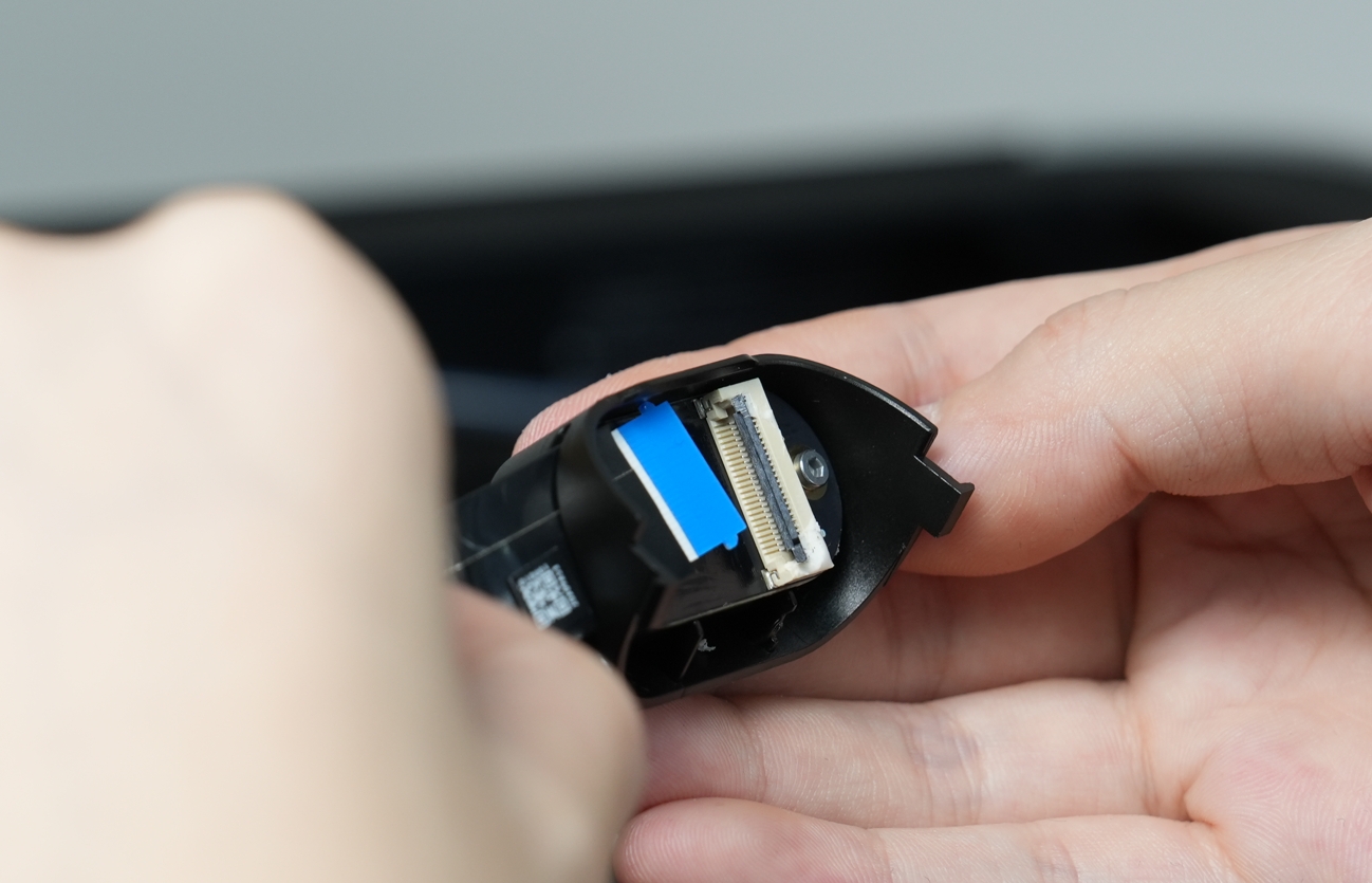
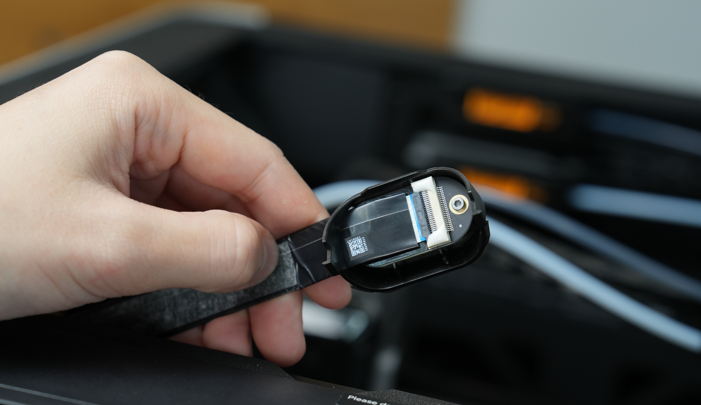
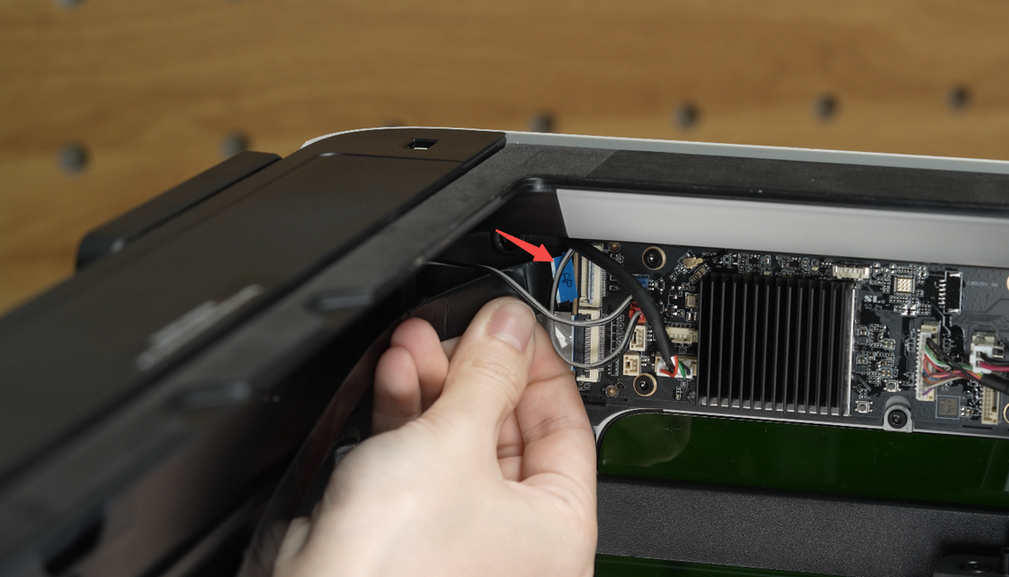
¶ Step 2: Disconnect the BirdsEye Camera Cable
Unfasten the black buckle above the birdseye camera cable and then pull out the birdseye camera cable.
 |
 |
¶ Install the BirdsEye Camera
¶ Step 1: Connect the BirdsEye Camera Cable
Plug the birdseye camera cable on the printer into the interface on the camera and fasten the black buckle.
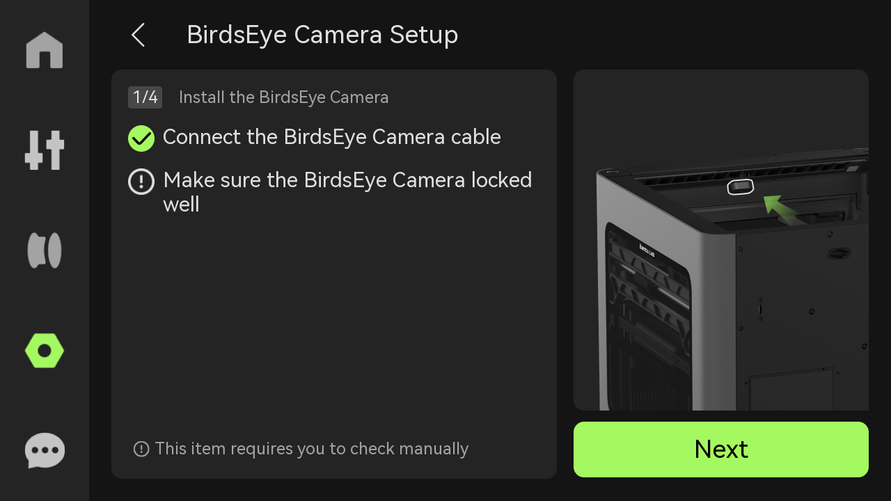
¶ Step 2: Install the BirdsEye Camera
Use an Allen key to gently push the LED ribbon cable inwards to prevent it from being damaged when installing the camera.

Align the buckle of the birdseye camera cover with the groove on the printer, press the birdseye camera cover with a little force, and insert it into the printer.
¶ Replace the BirdsEye Camera Cable
¶ Remove the BirdsEye Camera Cable
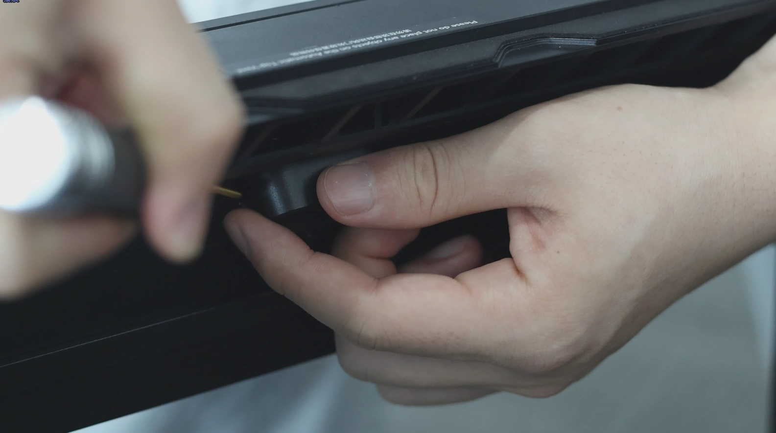
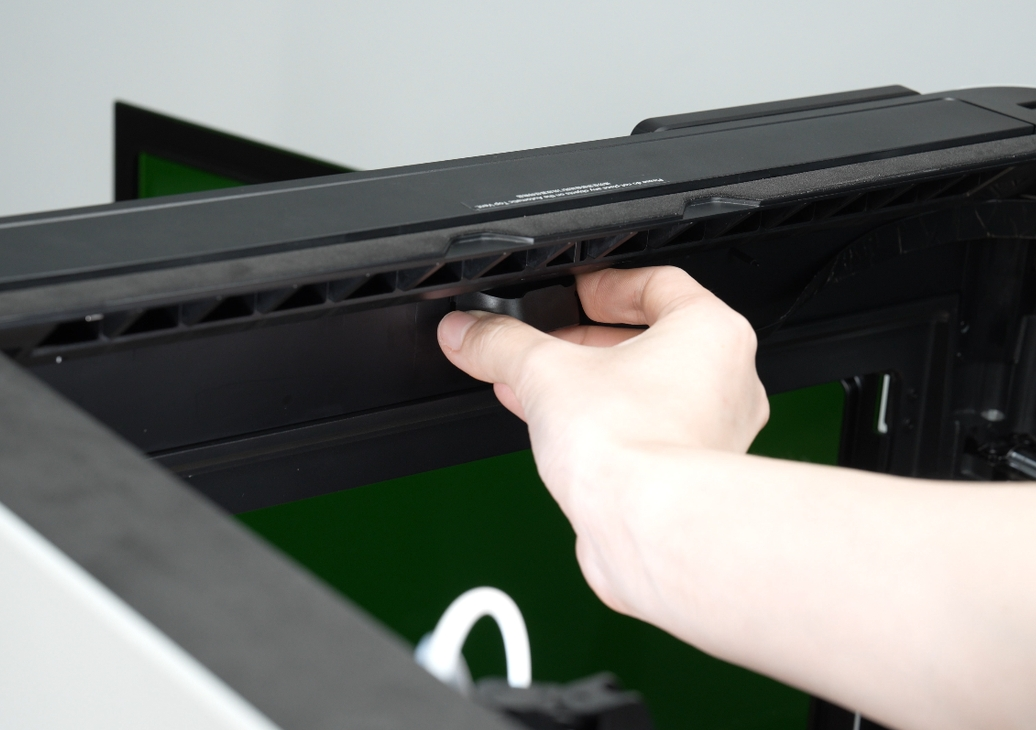
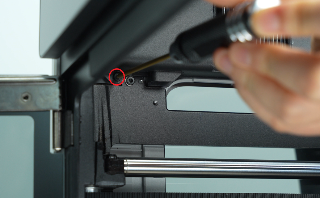
¶ Step 1: Open the AP Board Cover
Use an H2.0 Allen key to remove one AP board cover fixing screw (BT2.6×8), and then open the AP board cover from the side close to the front door.
 |
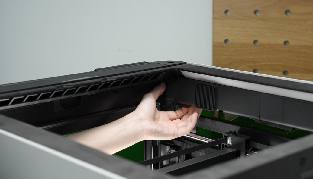 |
¶ Step 2: Remove the BirdsEye Camera
The birdseye camera is secured by clips. Press the clips on both sides of the birdseye camera cover while gently flipping it downward to release.
 |
 |
¶ Step 3: Remove the BirdsEye Camera Cable
Disconnect the birdseye camera cable from the AP board, then peel it off the upper frame and disconnect it from the birdseye camera.
 |
|
¶ Install the BirdsEye Camera Cable
¶ Step 1: Connect the BirdsEye Camera and the camera cable
- Connect the end of the cable without the "AP" label to the BirdsEye camera.
2. Use an Allen key to gently push the LED ribbon cable inwards to prevent it from being damaged when installing the camera.
- Install the BirdsEye camera. Align the two side buckles on the camera housing with the two small grooves on the printer.
.png) |
.png) |
.png)
- Wipe the camera lens with a non-woven cloth to remove any dust.
.png)
¶ Attach the BirdsEye Camera Cable
- Remove one fixed screw from the AP board cover.
.png)
2. Open the AP board cover.
.png)
3. When routing the cable, avoid the chamber temperature sensor and the flame sensor (marked in red boxes below).
.png) |
.png) |
Note: Apply continuous and firm pressure for about 30 seconds during attachment to ensure proper adhesion.
.png)
- Peel off the sticker backing from the cable buckle.
.png)
- Align the buckle with the screw hole on the upper cover and stick it in place.
.png) |
.png) |
Note: Apply continuous and firm pressure for about 15 seconds during attachment to ensure secure adhesion.
- Install the second buckle in the middle section between the BirdsEye camera and the first buckle, then press it firmly into place.
.png) |
.png) |
.png) |
.png) |
¶ Step 3: Connect the camera cable to the AP Board
- Open the black latch.
.png)
- Route the camera cable behind the other wires and connect it to the AP board.
.png)
3. Press the latch firmly to lock it.
.png)
- Close the AP board cover.
.png)
- Tighten the fixed screw.
.png) |
.png) |
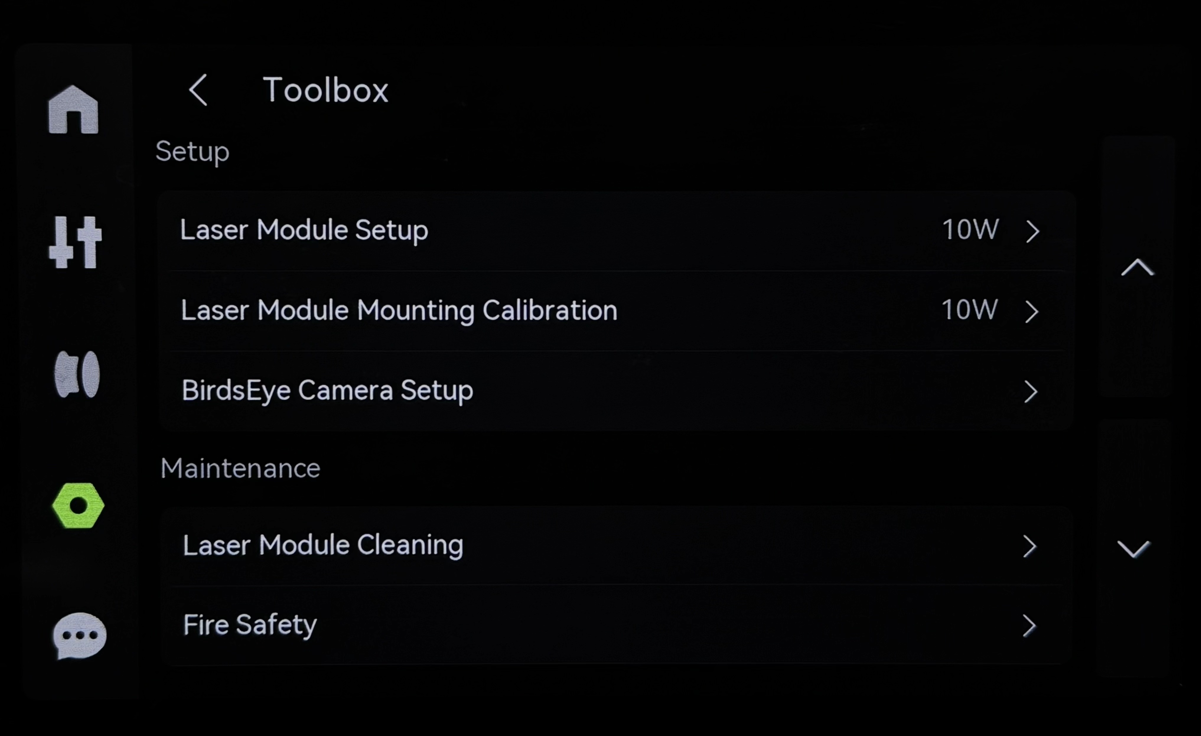
¶ Verify the Functionality
Once the laser module is installed, you will be prompted to initialize the birdseye camera. Follow the on-screen instructions to complete the setup.
- Enter the HMS page and click the "Begin Setup" button.
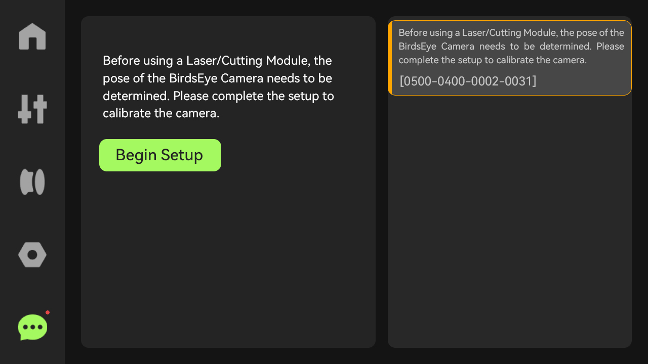
- Alternatively, access it from the Toolbox page and select "BirdsEye Camera Begin Setup".
¶ End Notes
We hope the detailed guide provided has been helpful and informative.
If this guide does not solve your problem, please submit a technical ticket, we will answer your questions and provide assistance.
If you have any suggestions or feedback on this Wiki, please leave a message in the comment area. Thank you for your support and attention!