¶ Filament Cutter Stopper
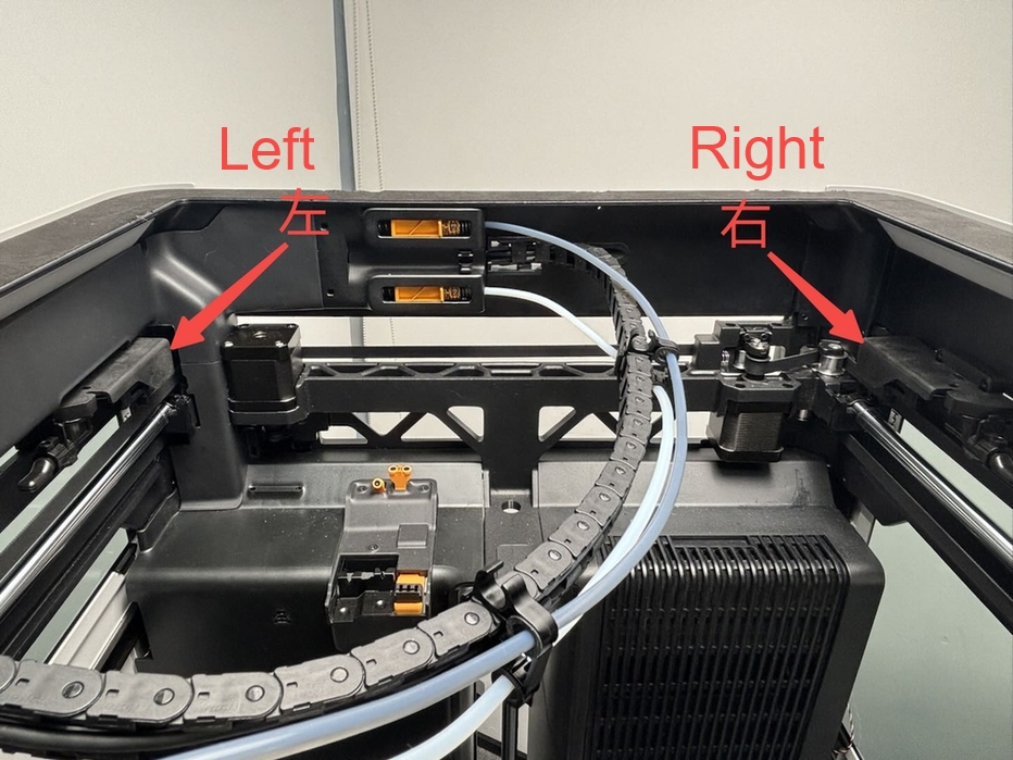
The filament cutter stopper assemblies are installed on the left and right sides inside the printer chamber. They are used to support the cutter, allowing it to cut the filament and complete functions such as material changing and unloading. There are two filament cutter stopper assemblies on the H2D, which are symmetrically designed with chirality.
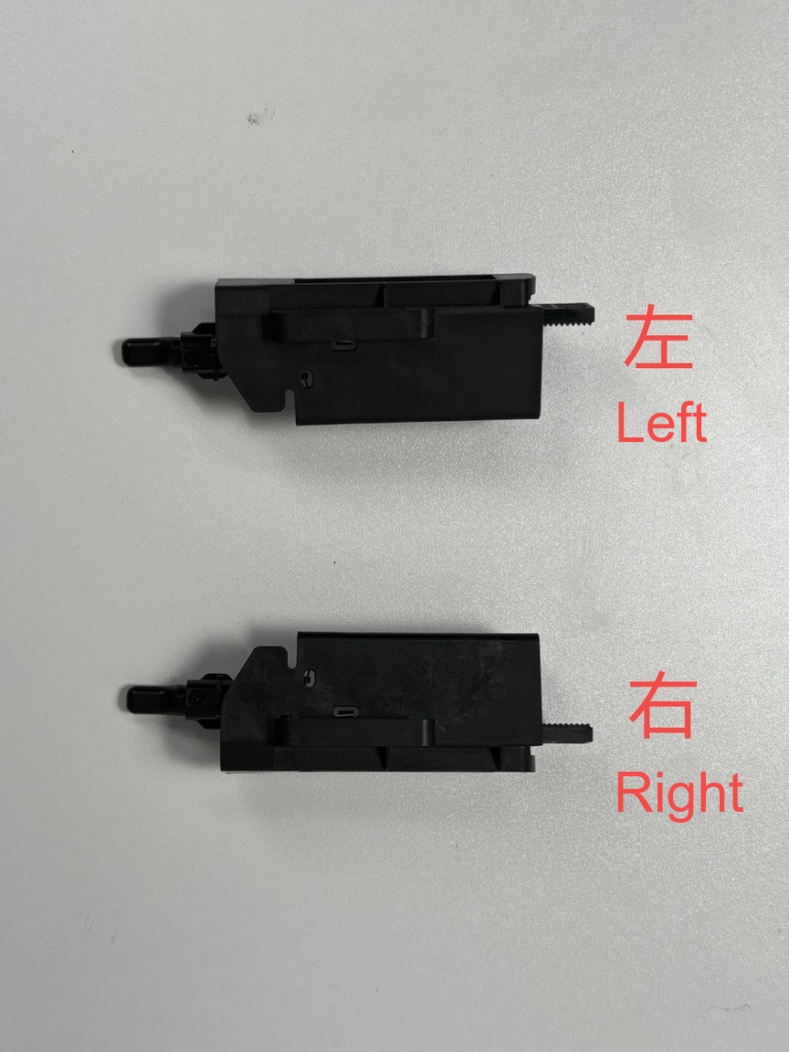
The Filament Cutter Stopper spare parts are available in left and right versions:
Filament Cutter Stopper - Left:
-
Filament Cutter Stopper - Left * 1
-
BT2.6x8 * 2
-
M2.5x5 * 2
Filament Cutter Stopper - Right:
-
Filament Cutter Stopper - Right * 1
-
BT2.6x8 * 2
-
M2.5x5 * 2
¶ When to Replace
- Filament cutter stopper is damaged.
¶ Required Tools and Materials
-
New filament cutter stopper
-
H2.0 Allen key
Specifications and quantities of screws involved in replacing the H2D filament cutter stopper (it is recommended to keep the removed screws properly to avoid loss):
| Specification | Image | Use | Position | Quantity | |
|---|---|---|---|---|---|
| M2x5 | Fix the filament cutter stopper - left/right (marked by the green square) |  |
4 (Each filament cutter stopper - left/right uses 2 pieces) | ||
| BT2x6 | Fix the filament cutter stopper - Left/Right (marked by the red square) | 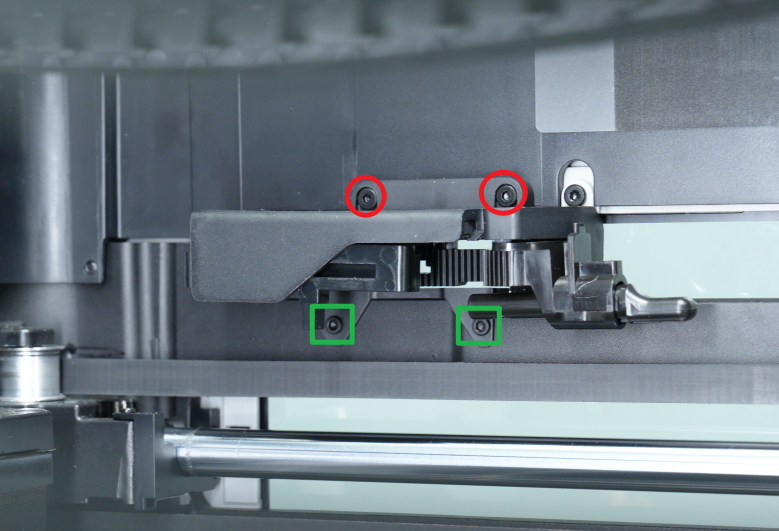 |
4 (Each filament cutter stopper - left/right uses 2 pieces) |
¶ Safety Warning
IMPORTANT!
It's crucial to power off the printer before conducting any maintenance work, including work on the printer's electronics and tool head wires. Performing tasks with the printer on can result in a short circuit, leading to electronic damage and safety hazards.
During maintenance or troubleshooting, you may need to disassemble parts, including the hotend. This exposes wires and electrical components that could short circuit if they contact each other, other metal, or electronic components while the printer is still on. This can result in damage to the printer's electronics and additional issues.
Therefore, it's crucial to turn off the printer and disconnect it from the power source before conducting any maintenance. This prevents short circuits or damage to the printer's electronics, ensuring safe and effective maintenance. For any concerns or questions about following this guide, we recommend submitting a technical ticket regarding your issue and we will do our best to respond promptly and provide the assistance you need.
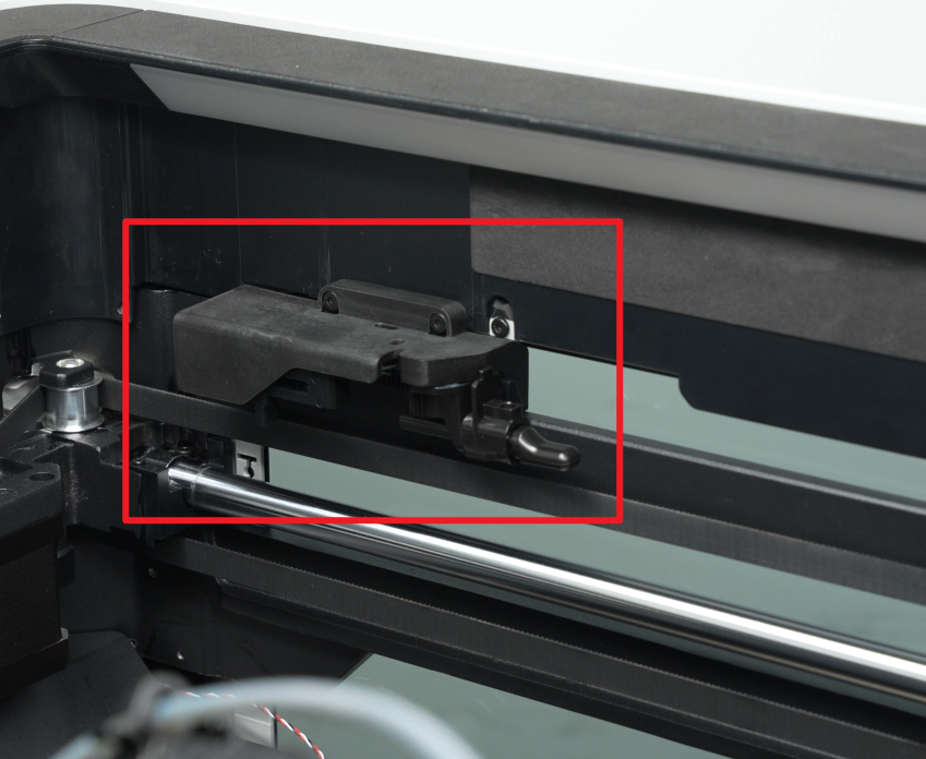
¶ Remove the Filament Cutter Stopper
You can use an H2.0 Allen key to remove the four fixing screws of the filament cutter stopper (Red circle marking: BT2.6x8; Green box marking: M2.5x5).
Note: The screw hole positions for both the left and right filament cutter stoppers are similar, with two screws in the upper row and two in the lower row.


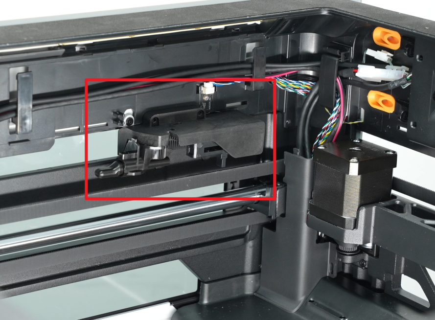
¶ Install the Filament Cutter Stopper
Before installing the filament cutter stopper, move the X-axis to the front (close to the front glass door).
Align the filament cutter stopper with the screw holes on the printer, then use an H2.0 Allen key to tighten the four fixing screws (Red circle marking: BT2.6x8; Green box marking: M2.5x5).
Note: The screw hole positions for both the left and right Filament Cutter Stoppers are similar, with two screws in the upper row and two in the lower row.

¶ Verify the Functionality
Check that the filament cutter stopper is stable and does not wobble, ensuring it can properly support the cutter.
¶ End Notes
We hope the detailed guide provided has been helpful and informative.
If this guide does not solve your problem, please submit a technical ticket, we will answer your questions and provide assistance.
If you have any suggestions or feedback on this Wiki, please leave a message in the comment area. Thank you for your support and attention!