¶ Important Reminder
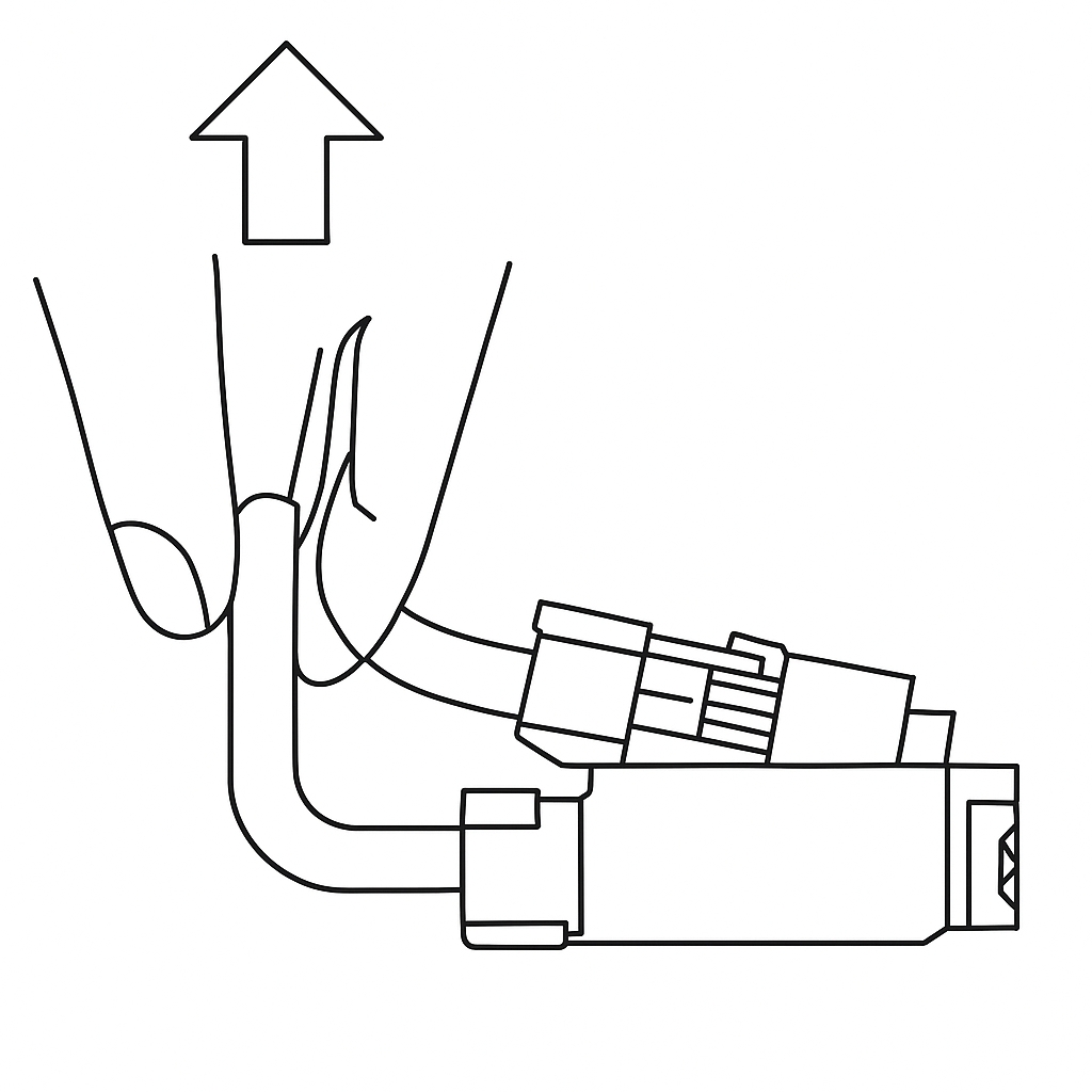
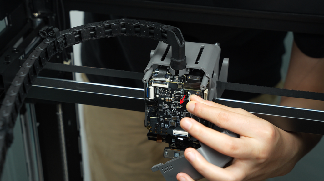
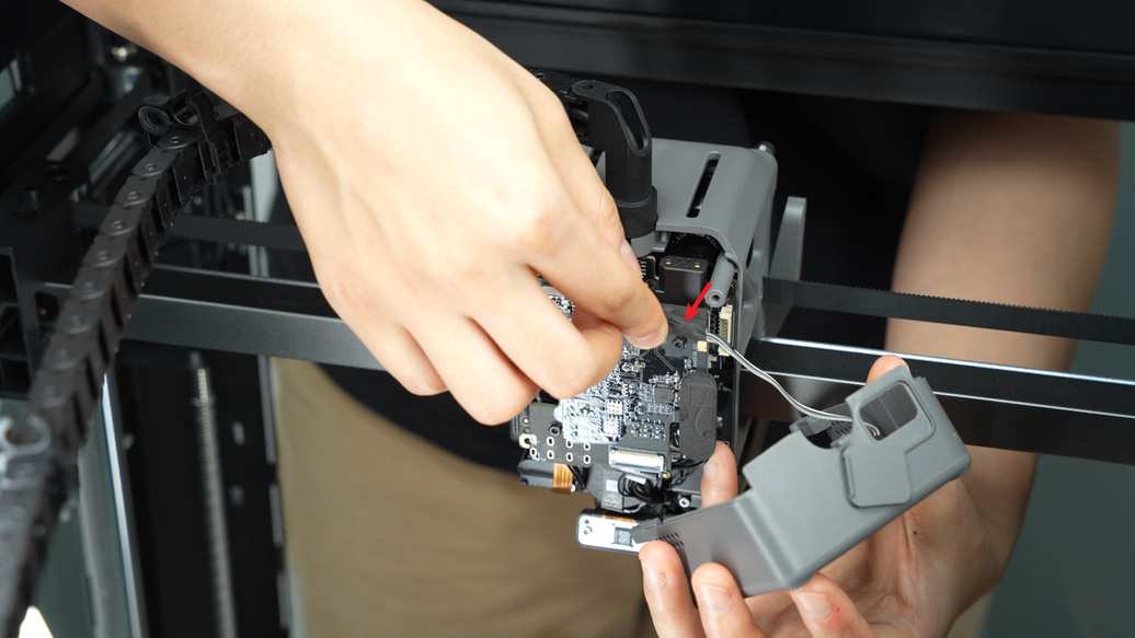
The part cooling fan connectors on the H2D feature this compact connector design.. When removing the connector, please hold the base of the connector with your hand and lift straight up, perpendicular to the PCB surface, to unlock it. Never apply force in the horizontal direction to avoid damaging the connector.
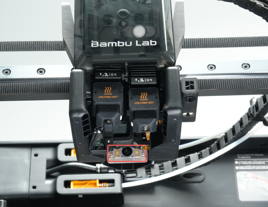
H2D is equipped with a nozzle camera for detecting abnormal printing conditions, including nozzle clumping, air printing, and spaghetti detection.
¶ When to replace
- Nozzle camera malfunction occurred
¶ Tools and materials needed
-
H2.0 Allen key
-
A new nozzle camera
¶ Safety Warning
IMPORTANT!
It's crucial to power off the printer before performing any maintenance work on the printer and its electronics, including toolhead wires, because leaving the printer on while conducting such tasks can cause a short circuit, which can lead to additional electrical damage and safety hazards.
When you perform maintenance or troubleshooting on the printer, you may be required to disassemble some parts, including the hotend. This process can expose wires and electrical components that could potentially short circuit if they come into contact with each other or with other metal or electrical components while the printer is still on. This can damage the electronics of the printer and cause further damage.
Therefore, it's essential to power off the printer and disconnect it from the power source before doing any maintenance work. This will prevent any short circuits or damage to the printer's electronics. By doing so, you can avoid potential damage to the printer's electronic components and ensure that the maintenance work is performed safely and effectively.
If you have any concerns or questions about following this guide, open a new ticket in our Support Page and we will do our best to respond promptly and provide you with the assistance you need.
¶ Disassembly Guide
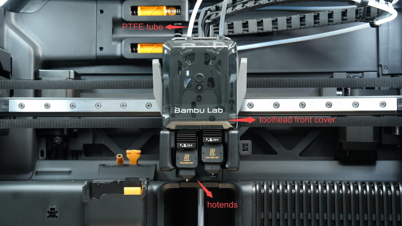
The disassembly steps in this wiki are excerpted from the comprehensive tool head disassembly guide. In fact, when replacing the nozzle camera, there is no need to remove the PTFE tube, tool head front cover, and left and right hotends. Please disassemble and assemble as needed.
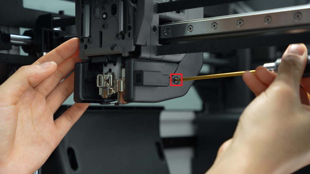
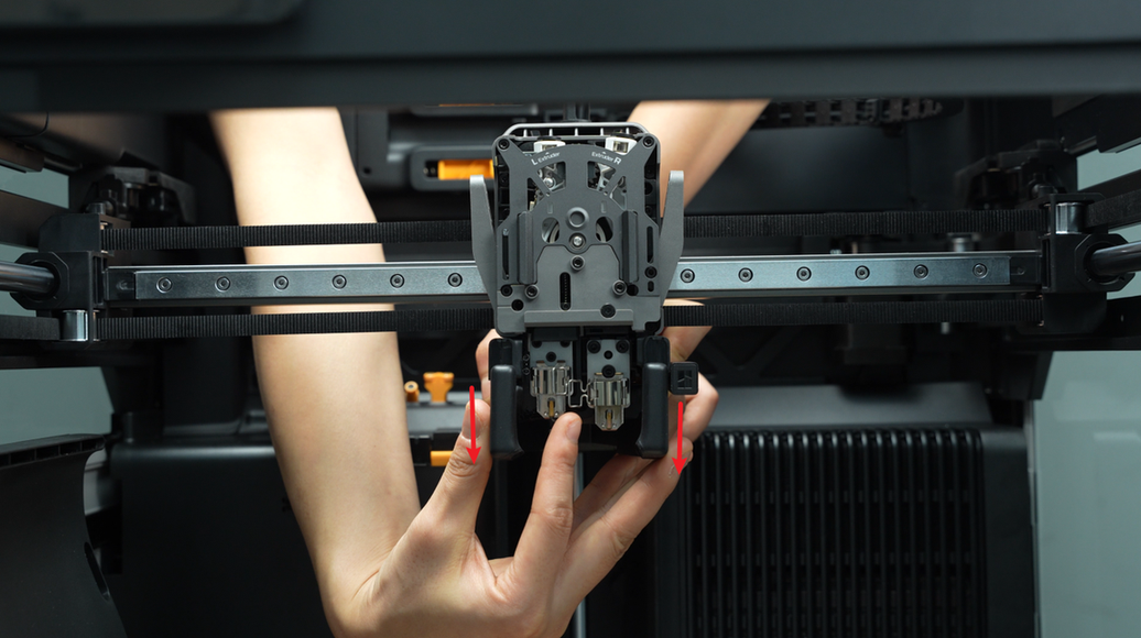
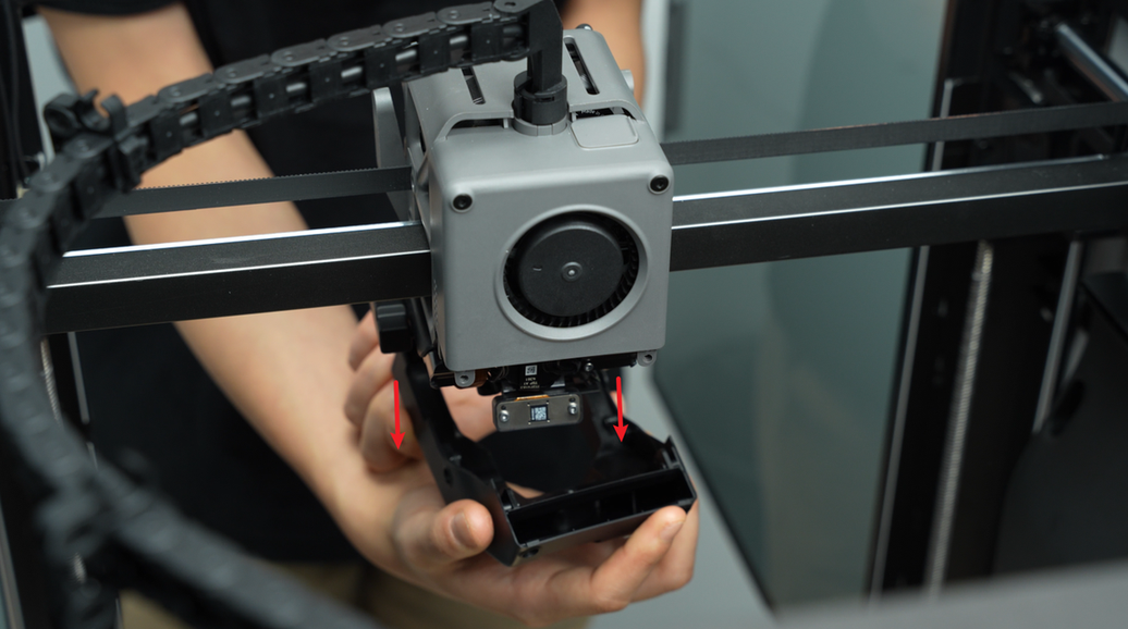
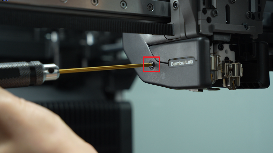
¶ Step 1: Remove the part cooling fan duct
Use a H2.0 hex key to remove the four fixed screws (BT3x8).


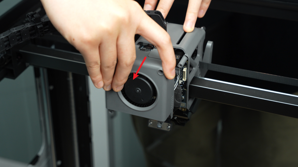
Hold the rear end of the part cooling fan duct and pull it downwards to remove the duct carefully.
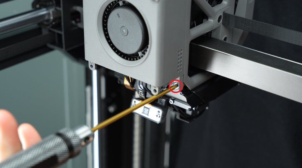
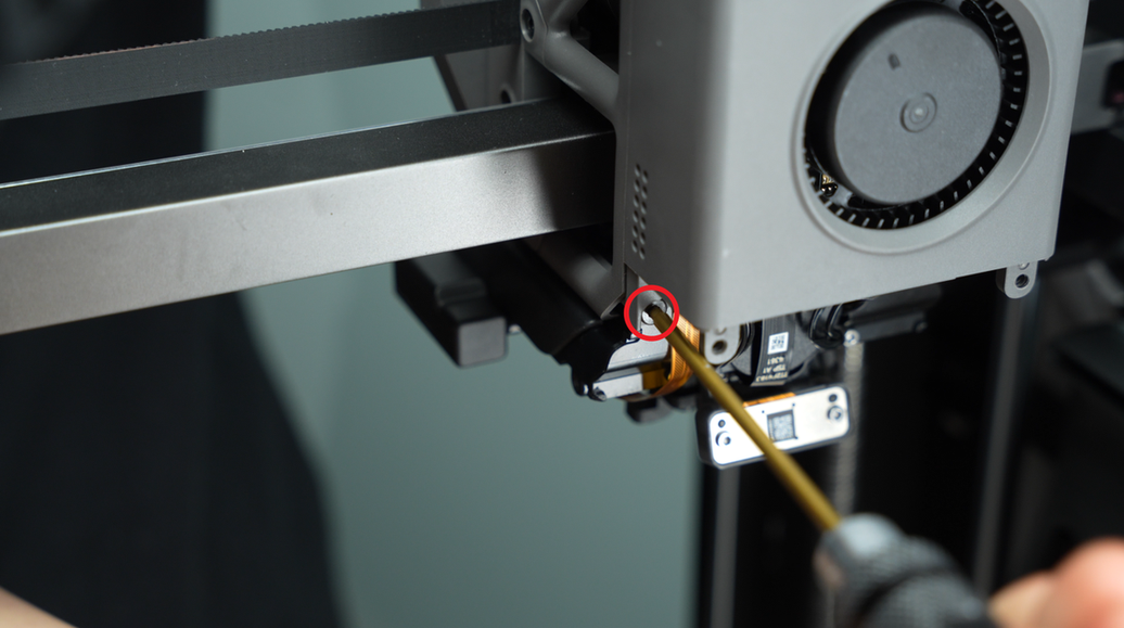
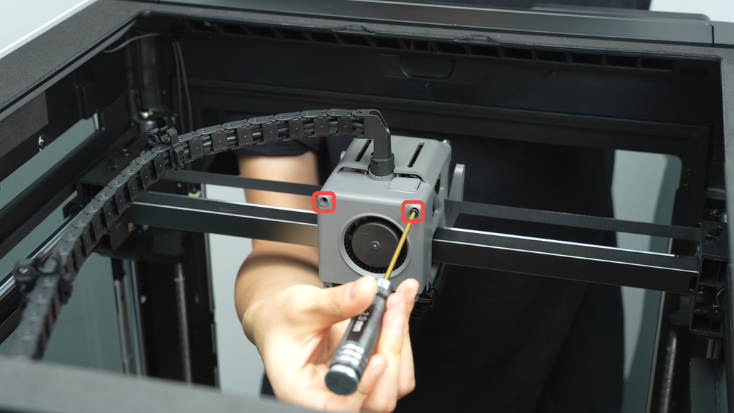
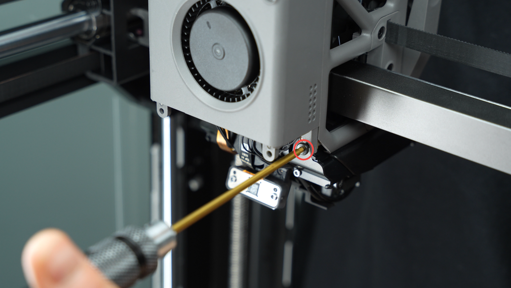
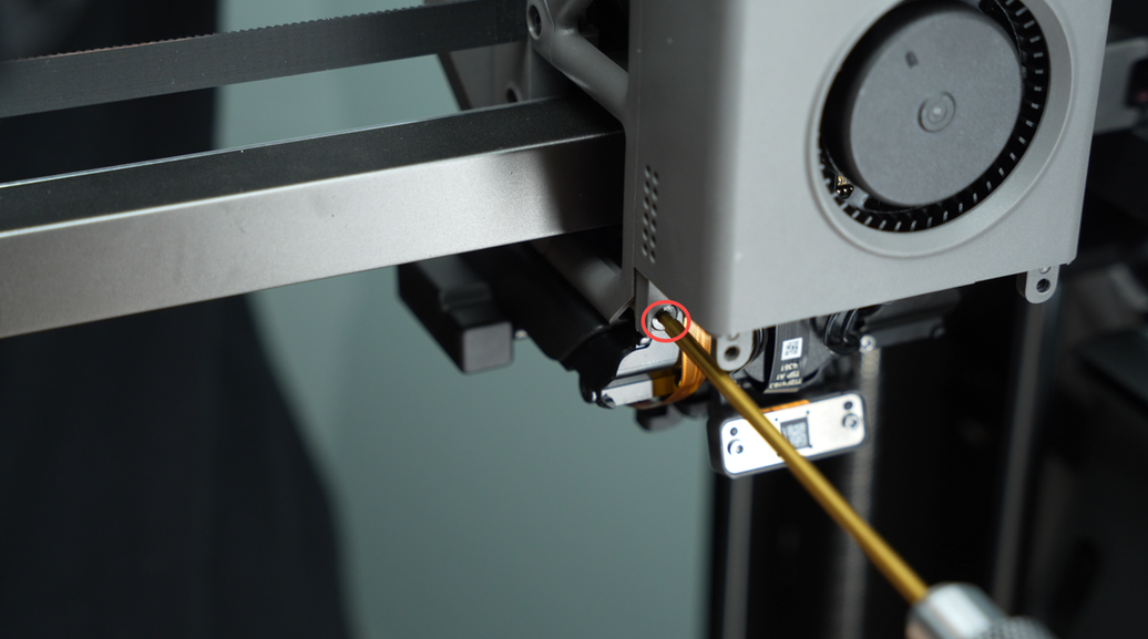
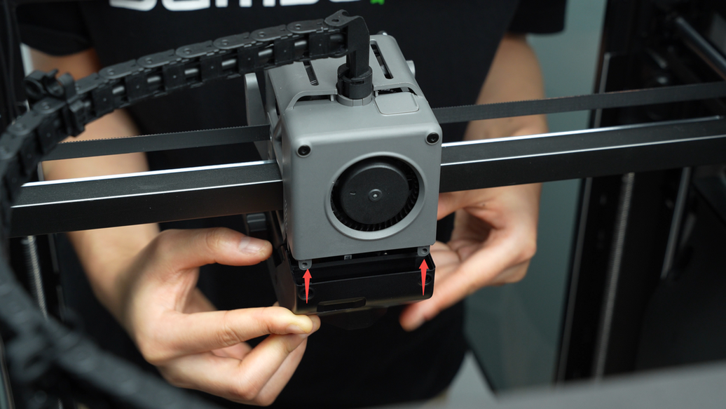
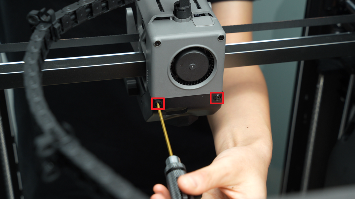
¶ Step 2: Remove the part cooling fan
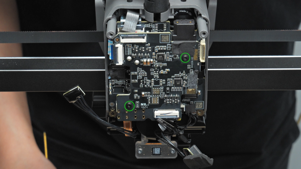
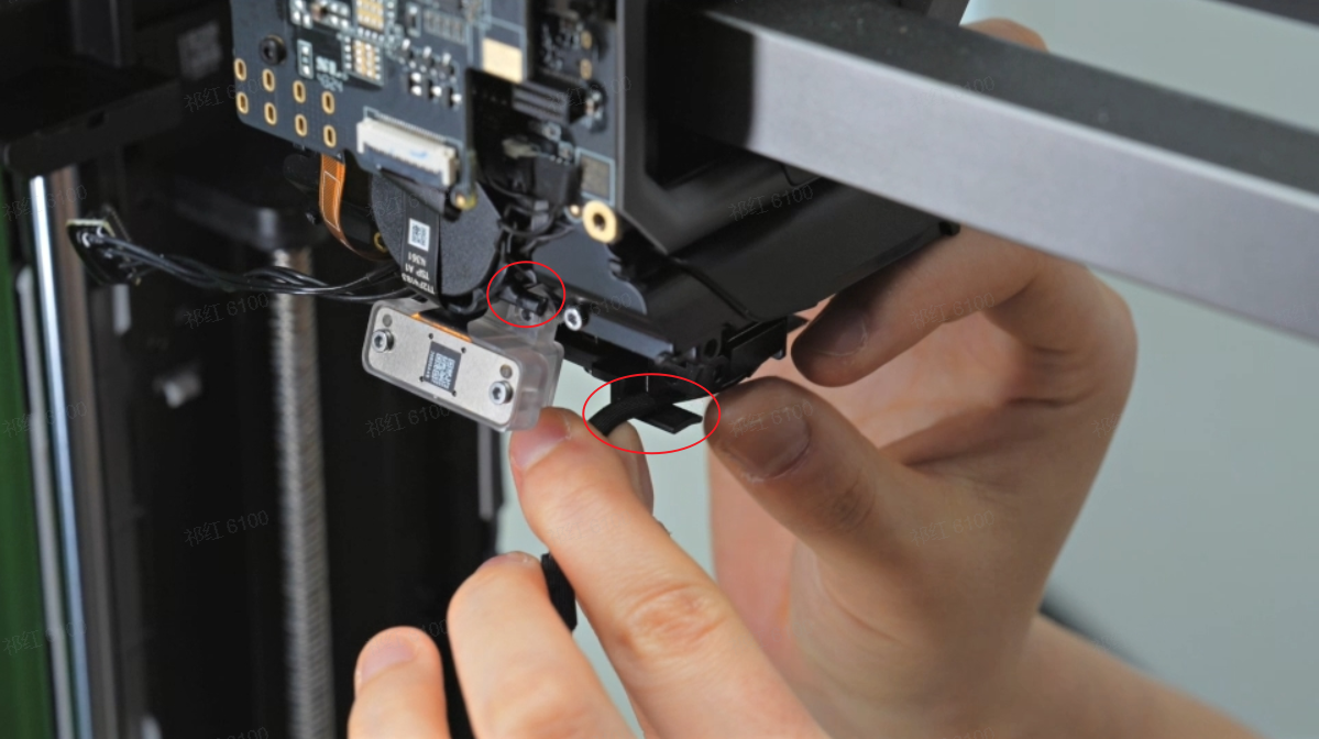
Use a H2.0 hex key to remove the four fixed screws.(BT3x20 marked with a square symbol, BT2.6x8 marked with a circle symbol)

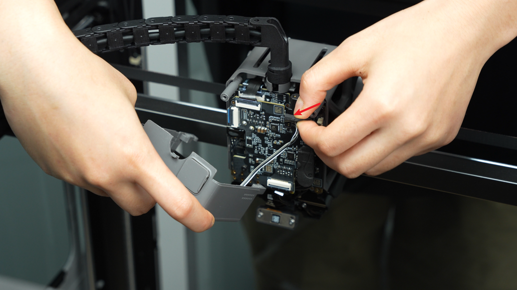
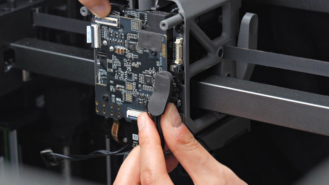
Tear off the acetate tape of the plug, then remove the plug. You can leave the removed tape on the circuit board for easier installation later on.
Please note that this type of plug should be carefully pushed upward along the plane where the plug is located, rather than pulled out along the direction of the cable. Please follow the operation in the video to avoid damaging the plug.
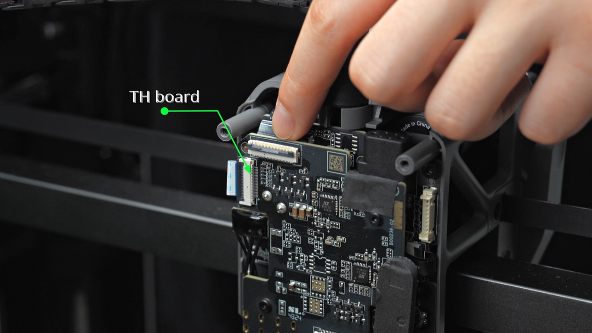
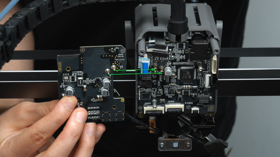
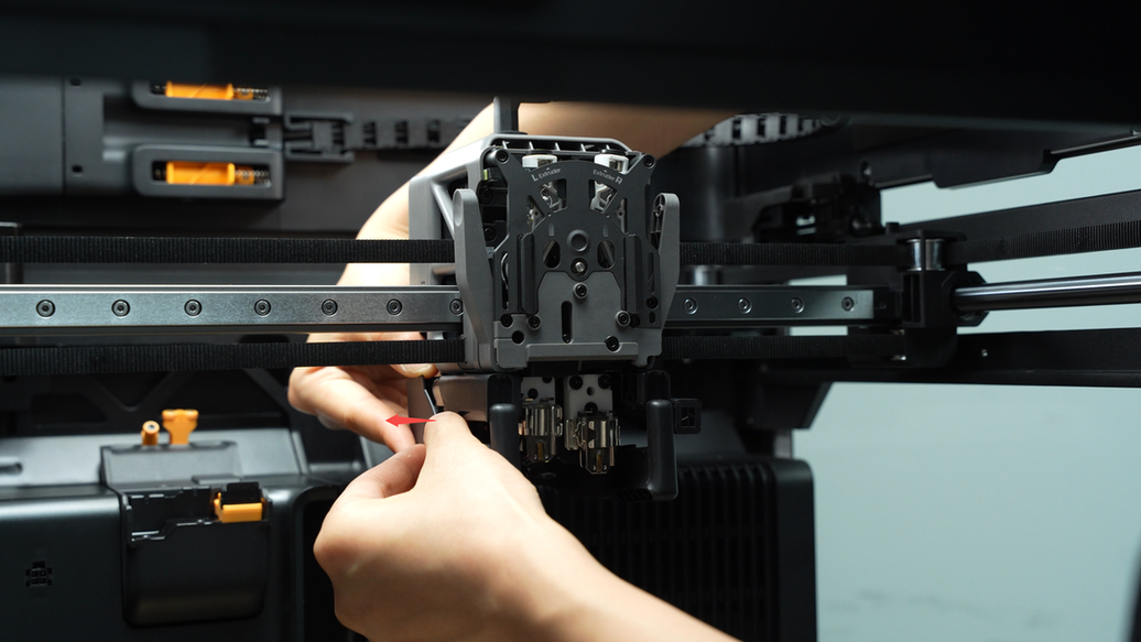
¶ Step 3: Remove the TH connection board
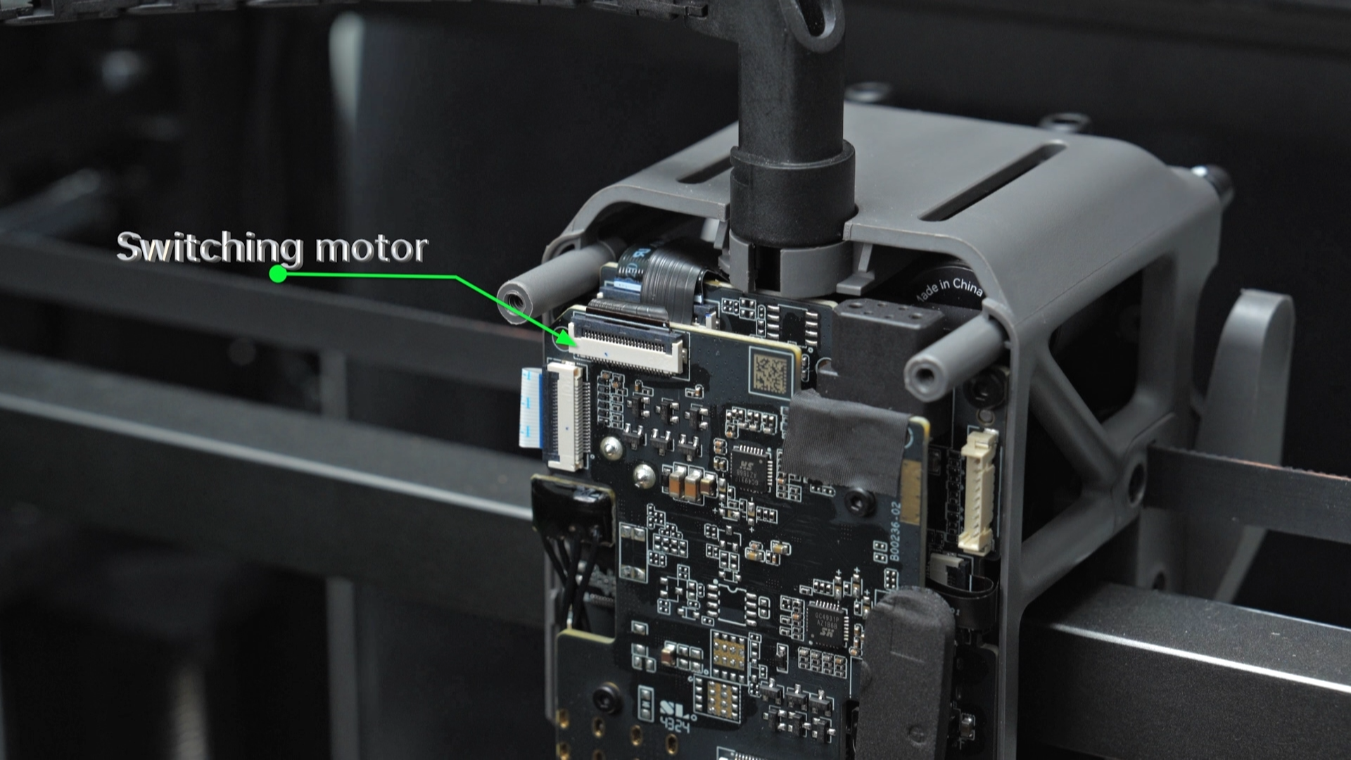
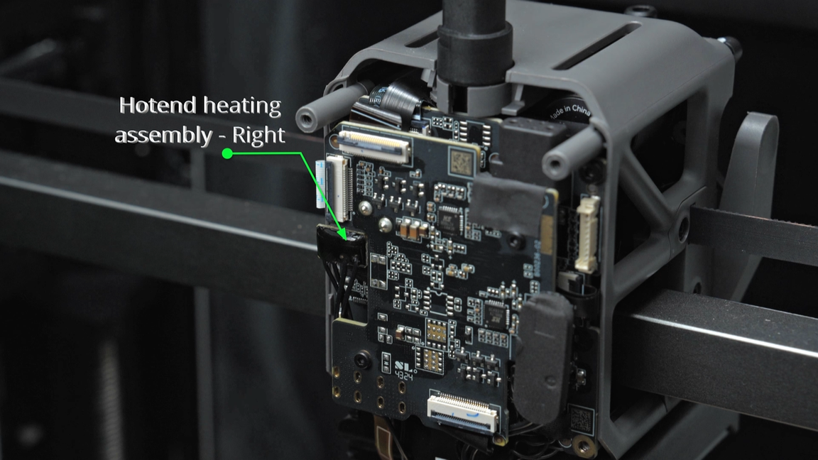
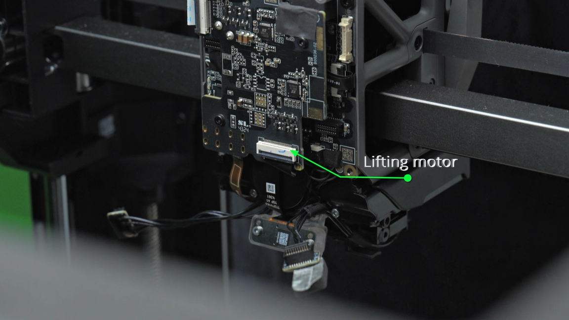
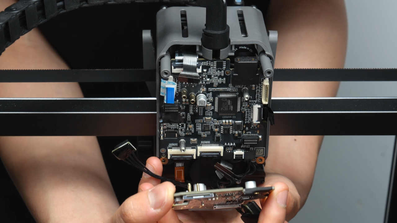
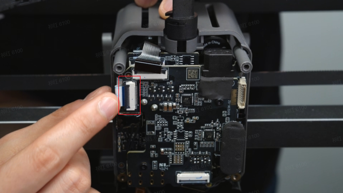
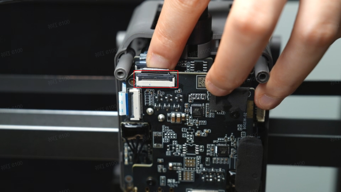
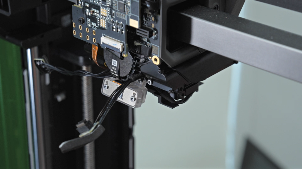
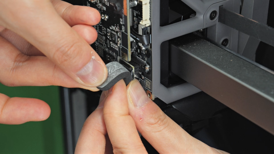
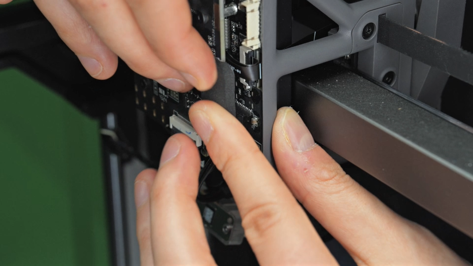
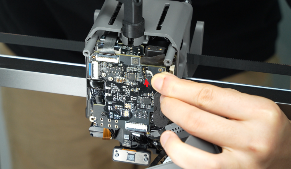
Disconnect the switching motor plug, TH board plug, right hotend heating assembly plug, left hotend heating assembly plug along with the foam pad (the left hotend heating assembly plug is located on the TH board, the foam pad is located on the TH connection board), and the lifting motor plug in sequence from the TH connection board.&##x20;
Please note that the FPC cables are secured by clips, you need to unlock the clips before pulling out the FPC cables.
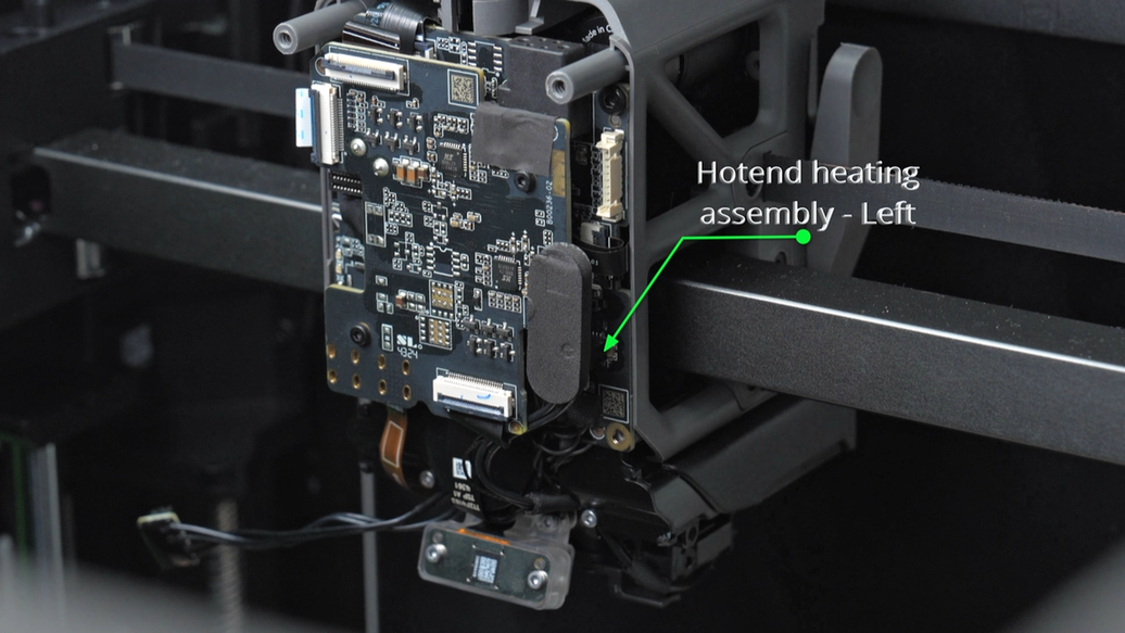
When tearing off the foam pad on the left hotend heating assembly plug, it is recommended to loosen the plug first, and then tear it off from the bottom up. This ensures the integrity of the foam pad.
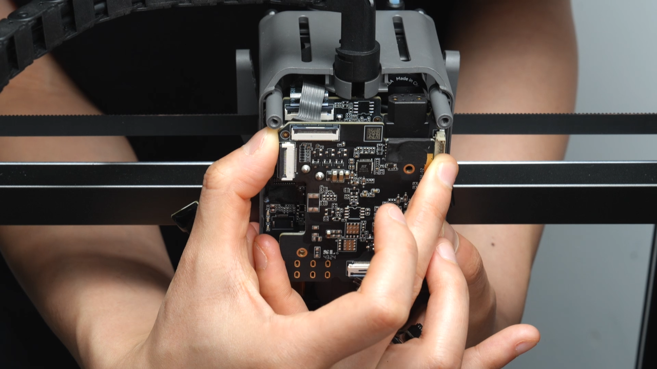
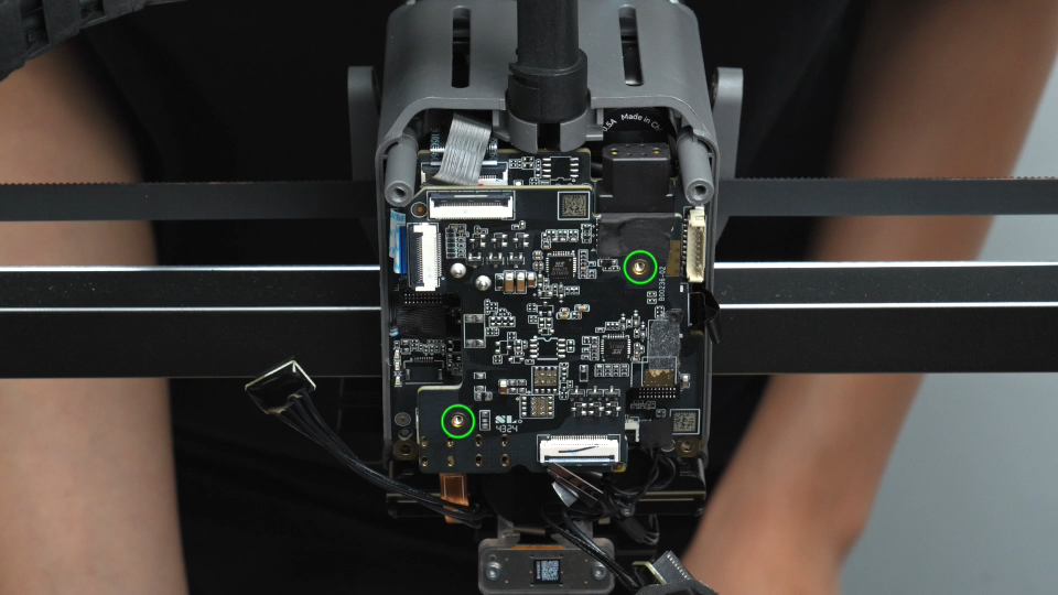
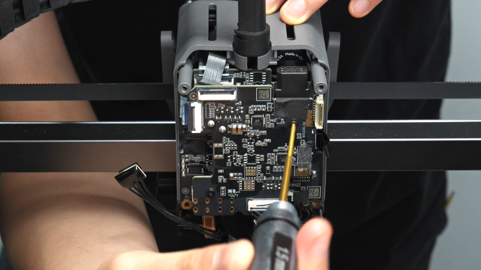
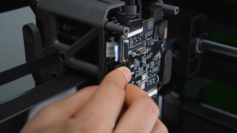
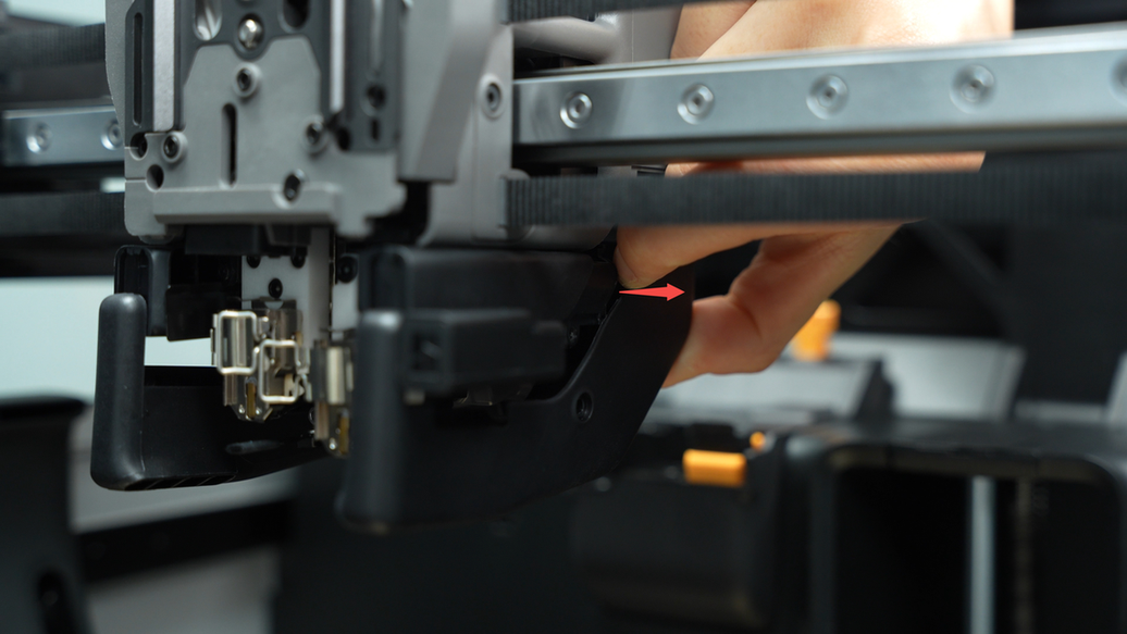
Unscrew the two fixing screws on the TH connection board, grip the sides of the connection board with one hand, and gently shake near the switching motor plug with the other hand to remove the TH connection board.
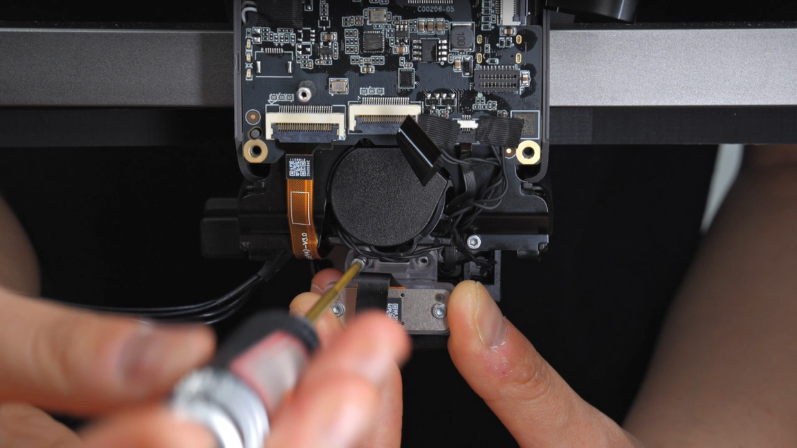
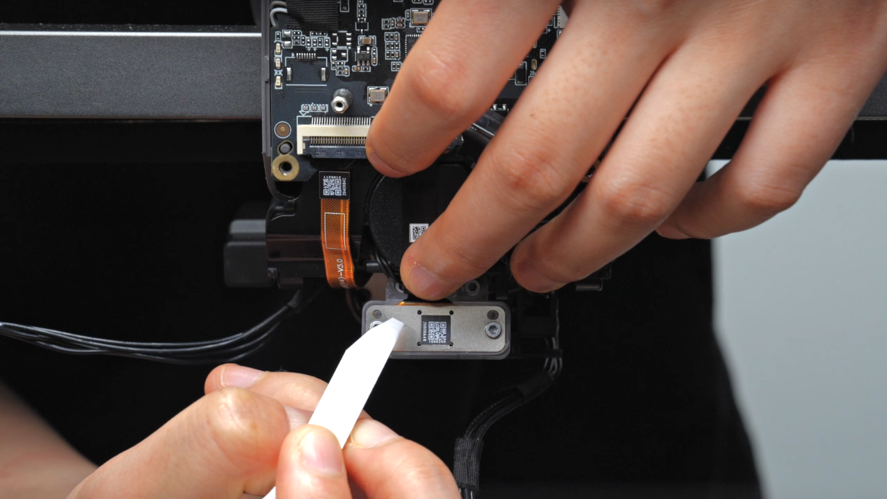
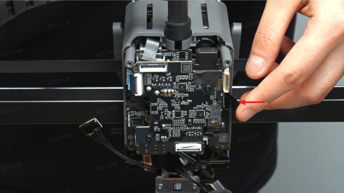
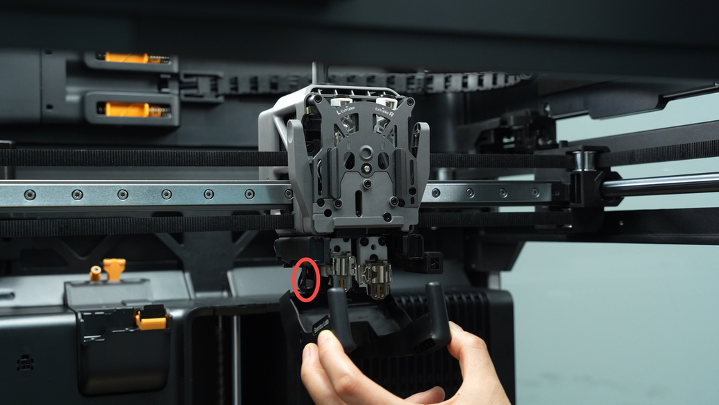
¶ Step 4: Remove the nozzle camera
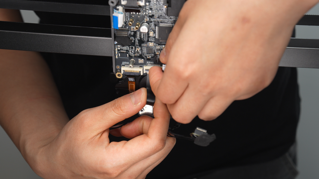
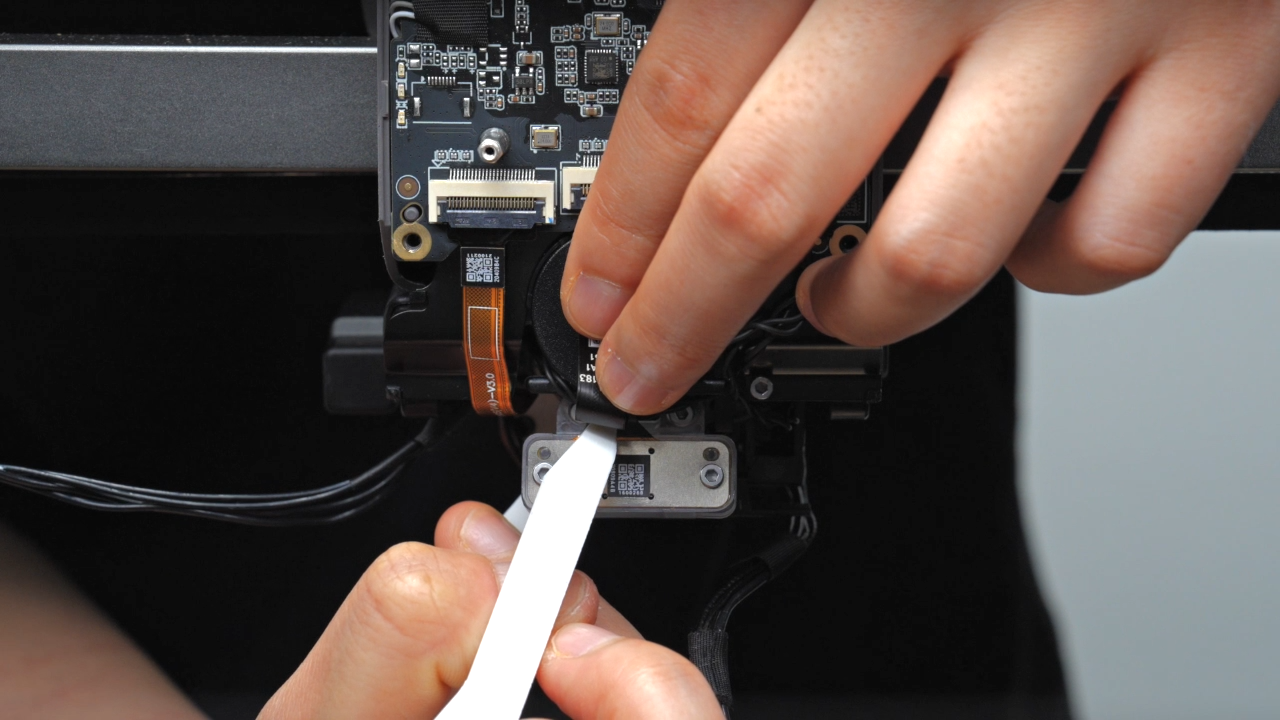
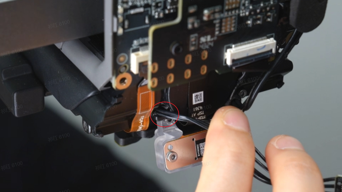
The FPC cable of the nozzle camera is stuck on the rear cover of the lifting motor. Before removal, use a tweezer to pull out a portion of the reserved FPC cable, allowing space for fingers to pass through and grip the FPC cable.&##x20;
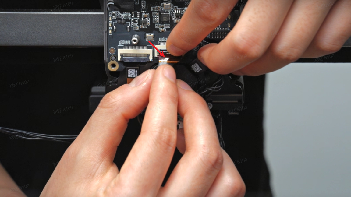
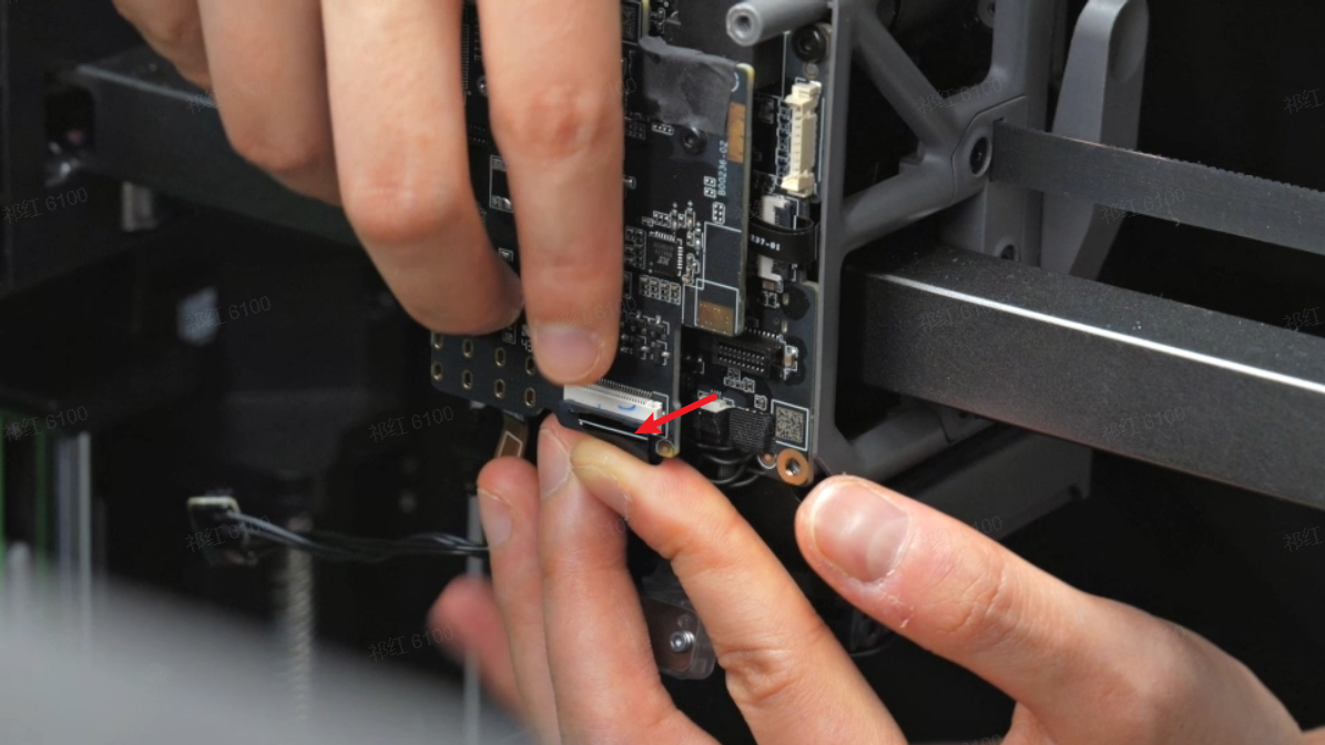
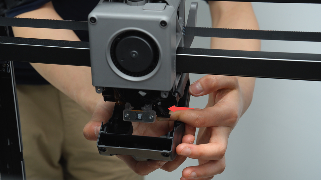
Then, release the socket latch of the nozzle camera and gradually loosen the FPC cable by hand before finally disconnecting the FPC cable.
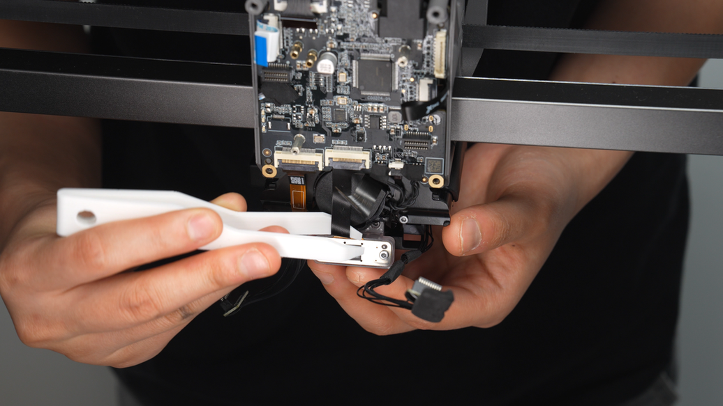
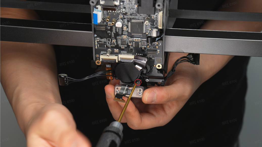
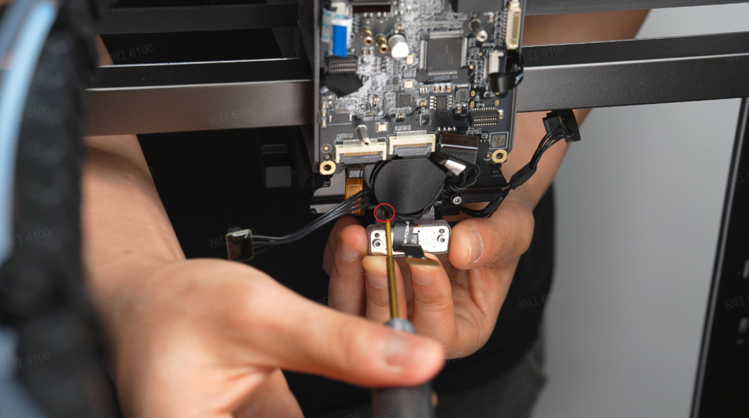
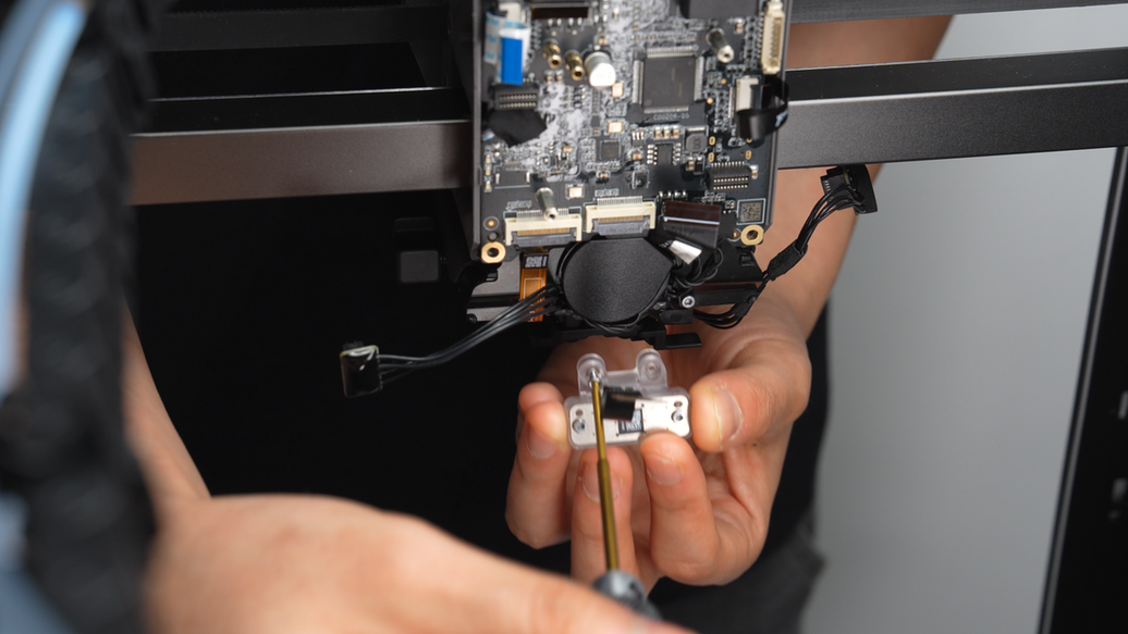
Unscrew the two fixing screws of the nozzle camera and remove the nozzle camera.
¶ Assembly Guide
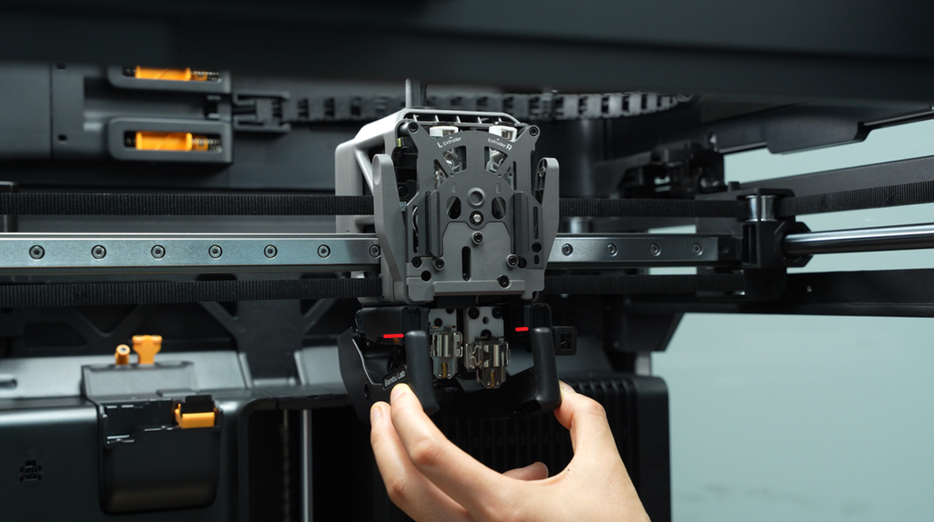
¶ Step 1: Install the nozzle camera
Tighten the two fixing screws of the nozzle camera.
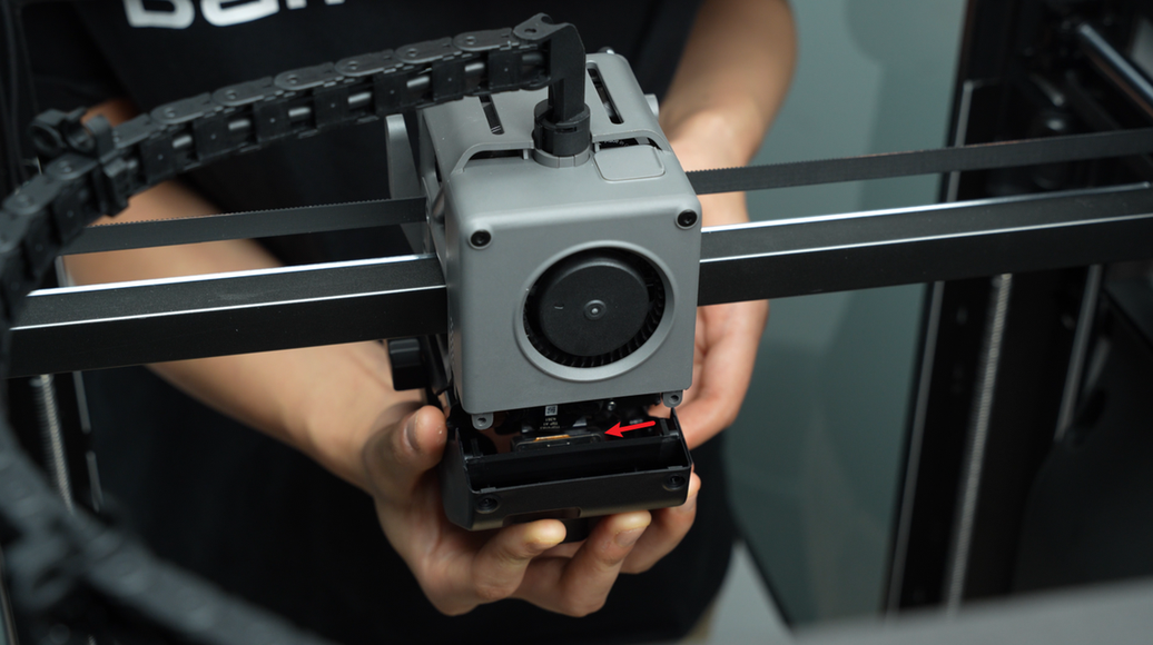
Reinsert the FPC cable of the nozzle camera into the connector, ensuring that the head of the FPC cable is fully inserted into the connector (the white line is in a horizontal position, indicating that the FPC cable is properly inserted), and then close the socket.
Use a tweezer to tuck the lower part of the FPC cable into the gap above the nozzle camera. Then, press the FPC cable with your hand to smoothly adhere it to the rear cover of the lifting motor.
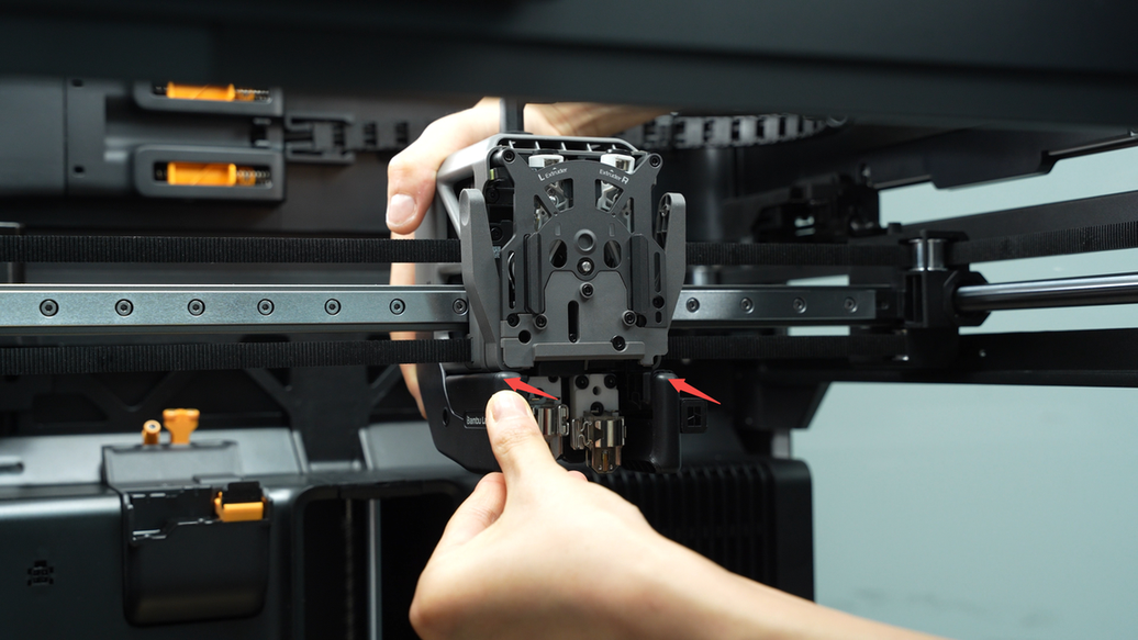
¶ Step 2: Install the TH connection board
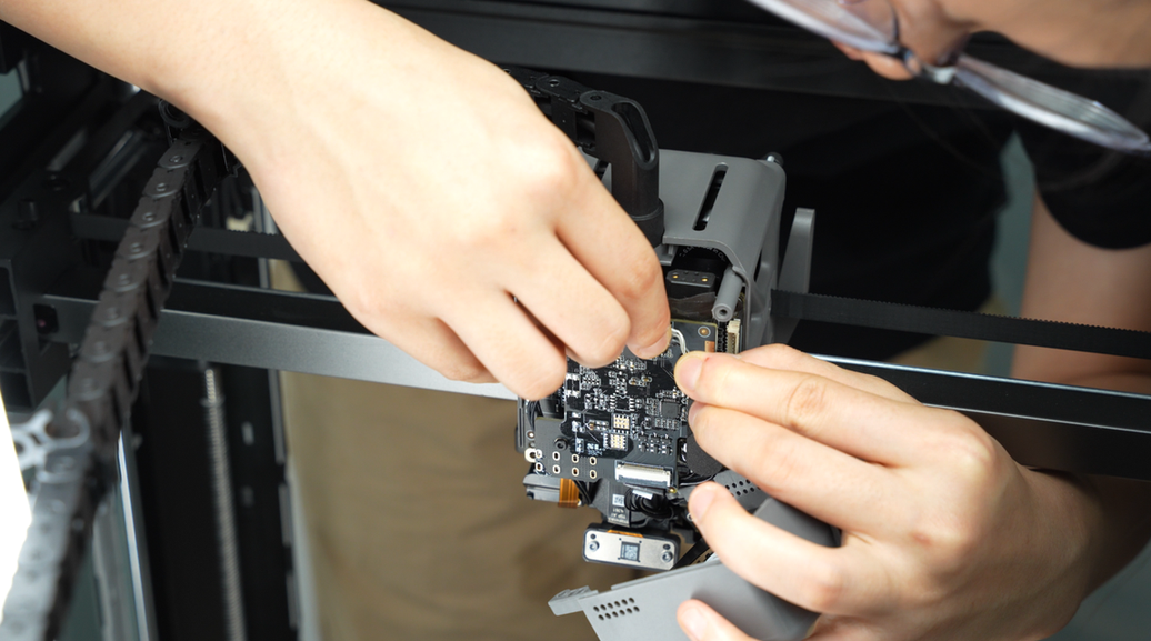
On the back of the TH connection board, there are two metal posts. Align them with the metal holes on the TH board and gently push them in while rocking back and forth to ensure the TH connection board is properly installed.

Next, tighten the two fixing screws on the TH connection board.
Tuck the side extruder hall sensor cable into the gap between the TH board and the TH connection board, then reconnect the lifting motor cable, left hotend heating assembly connector, right hotend heating assembly connector, TH board cable, and switching motor cable in sequence.
When connecting the lifting motor, TH board, and switching motor cables, ensure that the head of the FPC cable is fully inserted into the connector (all three FPC connectors have a mark line, with the line being horizontal indicating the FPC cable is properly inserted), and then close the socket. Finally, gently fold the FPC cable with your fingers.
When connecting the left and right hotend heating assembly connectors, it is important to plan the routing of the cables carefully.&##x20;
Thread the left hotend heating assembly cable through the bottom and back wire slots sequentially to prevent loose and difficult-to-organize cables.
Next, insert the left hotend heating assembly connector into the corresponding interface on the TH board, and then firmly press the foam pad back in place.
When connecting the right hotend heating assembly, similarly, thread the cable through the back wire slot before inserting the connector into the TH board.
¶ Step 3: Install the part cooling fan
With the metal side facing up, align the interface, then press down the part cooling fan plug and stick back the acetate tape.
Align the screw holes, cover back the part cooling fan, and tighten the 4 fixing screws.(BT3x20 marked with a square symbol, BT2.6x8 marked with a circle symbol)
¶ Step 4: Install the part cooling fan duct
The left hotend heating assembly cable needs to be installed in the cable management slot. Before installing the duct, make sure to press the hotend heating assembly cable into the cable management slot to prevent the duct from pressing on the cable.
First, install the front 1/4 of the duct to make it easier to tilt the rear half of the duct, avoiding interference with the nozzle camera. Then, grasp the rear half of the duct and push it upwards.
After pushing it in, gently bend the sides of the duct outward, slotting them onto the tool head on each side, and then firmly press the duct upwards to secure it in place.
Next, push the top of the front section of the duct forward to ensure a snug, gap-free fit.
Use an H2.0 hex key to tighten the four fixing screws (BT3x8).

¶ How to verify completion/success
Start the printer and initiate a print job. Observe during the printing process for any errors related to the nozzle camera. If there are no errors detected, it indicates that the installation of the nozzle camera is successful.
¶ End Notes
We hope the detailed guide provided has been helpful and informative.
If this guide does not solve your problem, please submit a technical ticket, we will answer your questions and provide assistance.
If you have any suggestions or feedback on this Wiki, please leave a message in the comment area. Thank you for your support and attention!