¶ Quick Change Tool Interface
 |
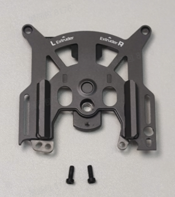 |
The spare parts for the quick change tool interface include the following:
- Quick change tool interface * 1
- M2.5x7 screw * 2
¶ When to Use
The quick change tool interface is damaged.
¶ Tools and Materials Needed
-
New quick change tool interface
-
H2.0 Allen key
¶ Safety Warning
IMPORTANT!
It's crucial to power off the printer before conducting any maintenance work, including work on the printer's electronics and tool head wires. Performing tasks with the printer on can result in a short circuit, leading to electronic damage and safety hazards.
During maintenance or troubleshooting, you may need to disassemble parts, including the hotend. This exposes wires and electrical components that could short circuit if they contact each other, other metal, or electronic components while the printer is still on. This can result in damage to the printer's electronics and additional issues.
Therefore, it's crucial to turn off the printer and disconnect it from the power source before conducting any maintenance. This prevents short circuits or damage to the printer's electronics, ensuring safe and effective maintenance. For any concerns or questions about following this guide, we recommend submitting a technical ticket regarding your issue and we will do our best to respond promptly and provide the assistance you need.
¶ Video Guide
Note: This video demonstrates the disassembly of the entire extruder assembly. However, when replacing only the extruder front cover, it is not necessary to remove the PTFE tube or the right hotend. The video is for reference only—please follow the illustrated disassembly guide below for detailed steps.
¶ Disassembly Steps
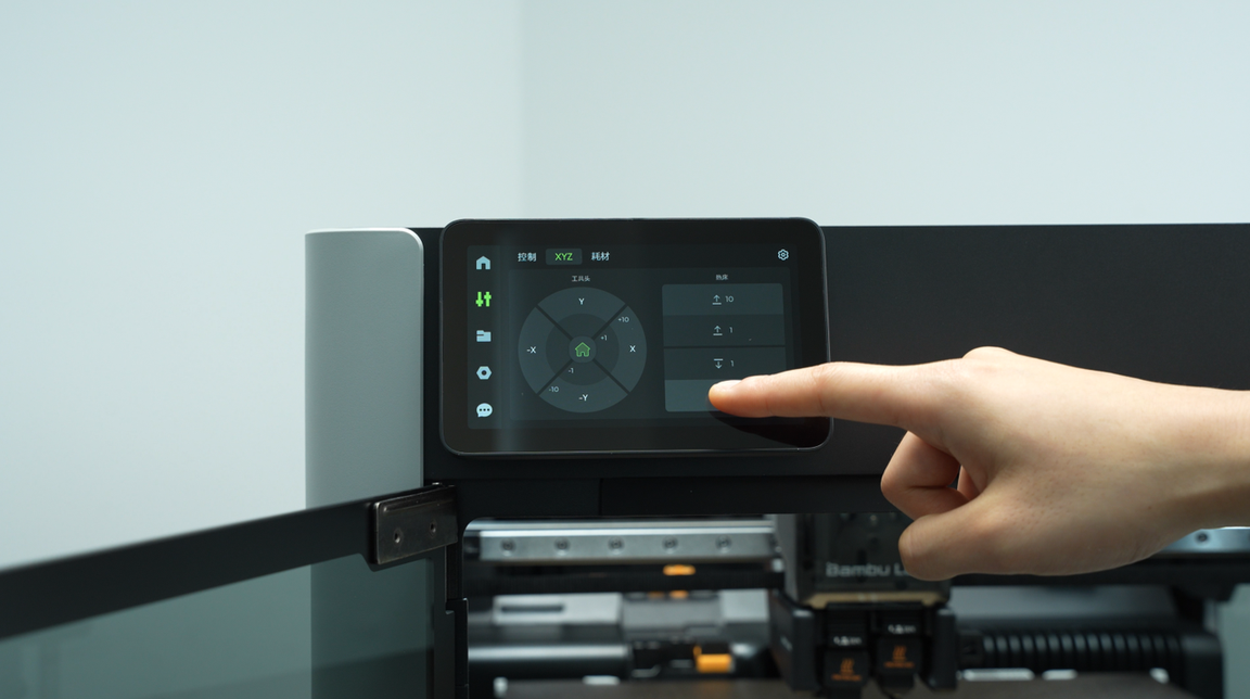
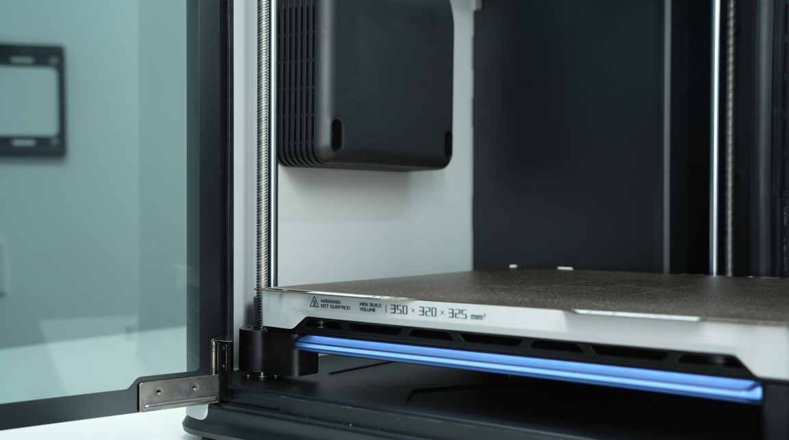
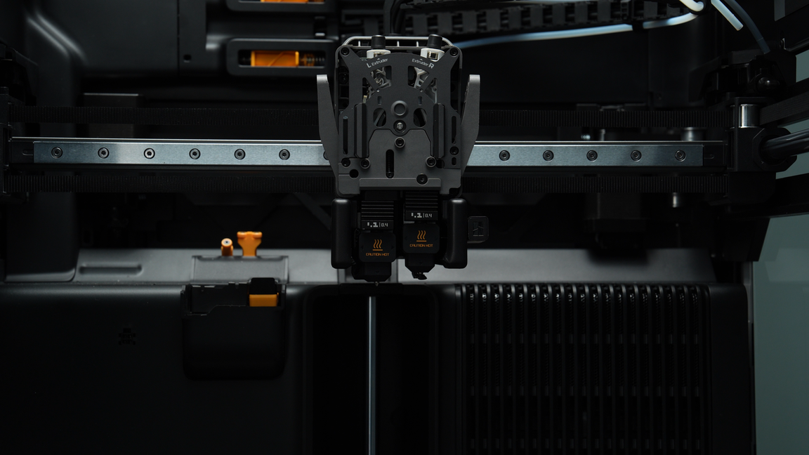
¶ Step 1: Lower the heatbed to create space for toolhead disassembly
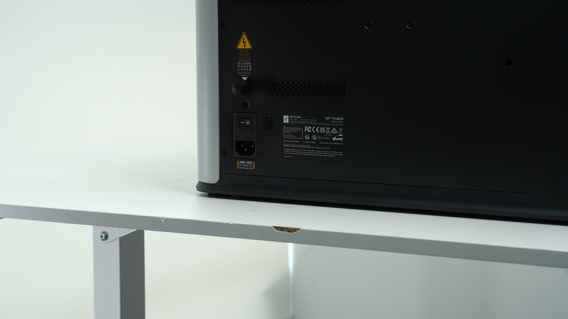
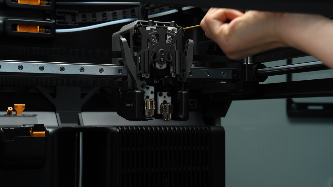
Lower the heatbed through the screen to facilitate the disassembly of the toolhead. Make sure the hotend is at room temperature and then power off the printer.
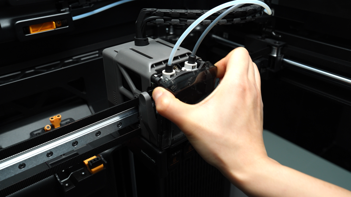
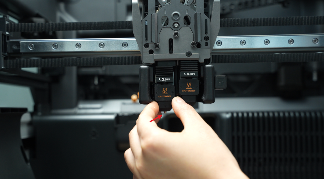
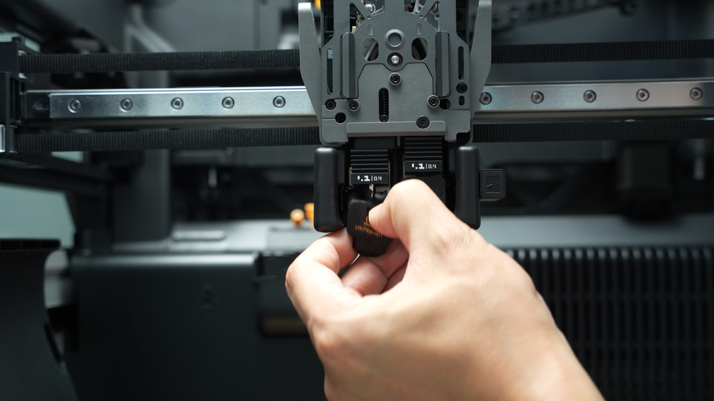
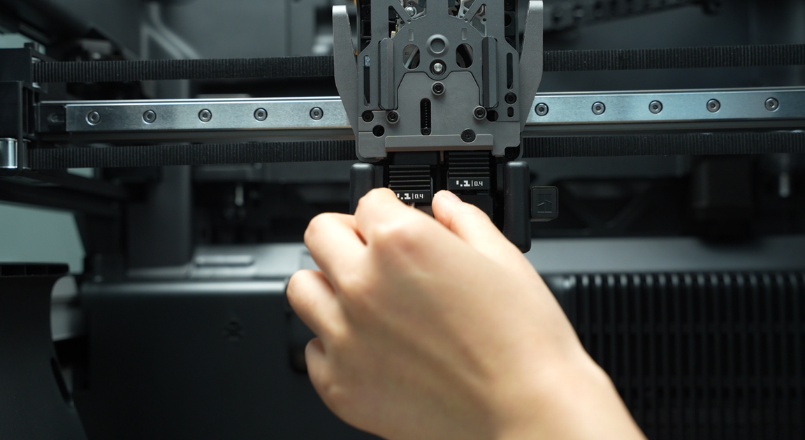
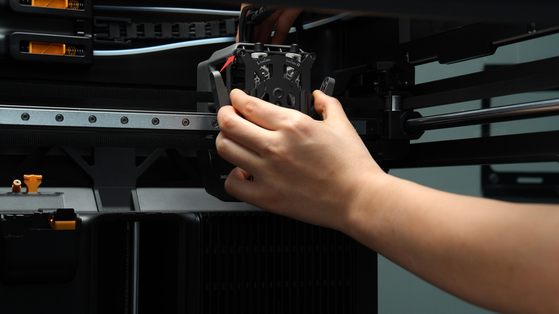
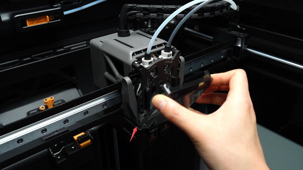
¶ Step 2: Remove the toolhead front cover
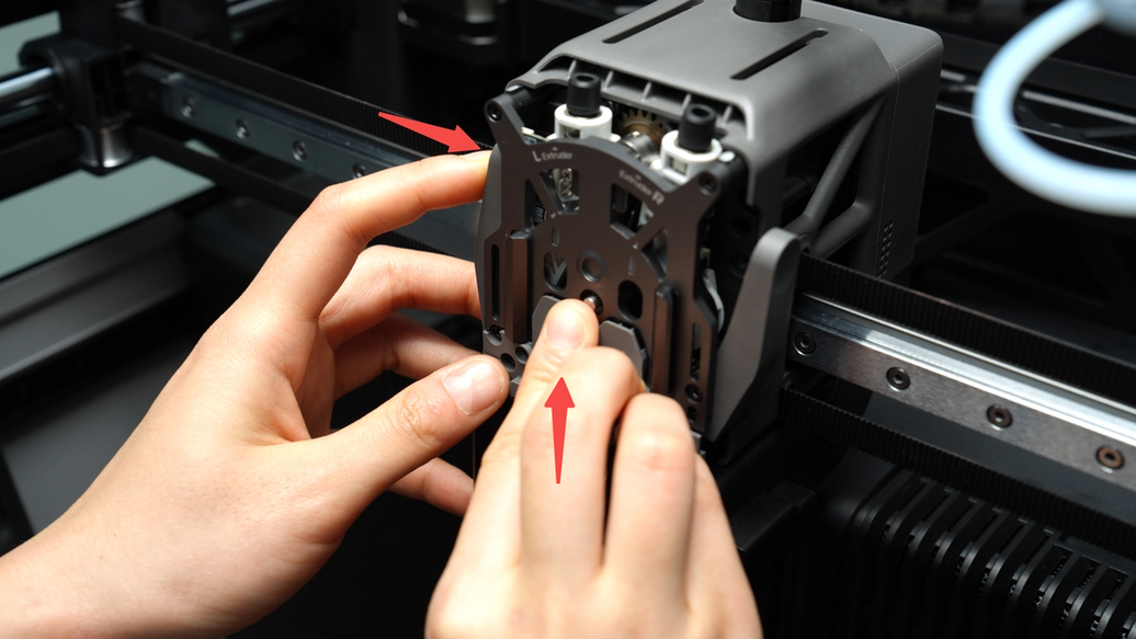
Pinch the top two corners of the toolhead front cover and lift upwards to remove the front cover.
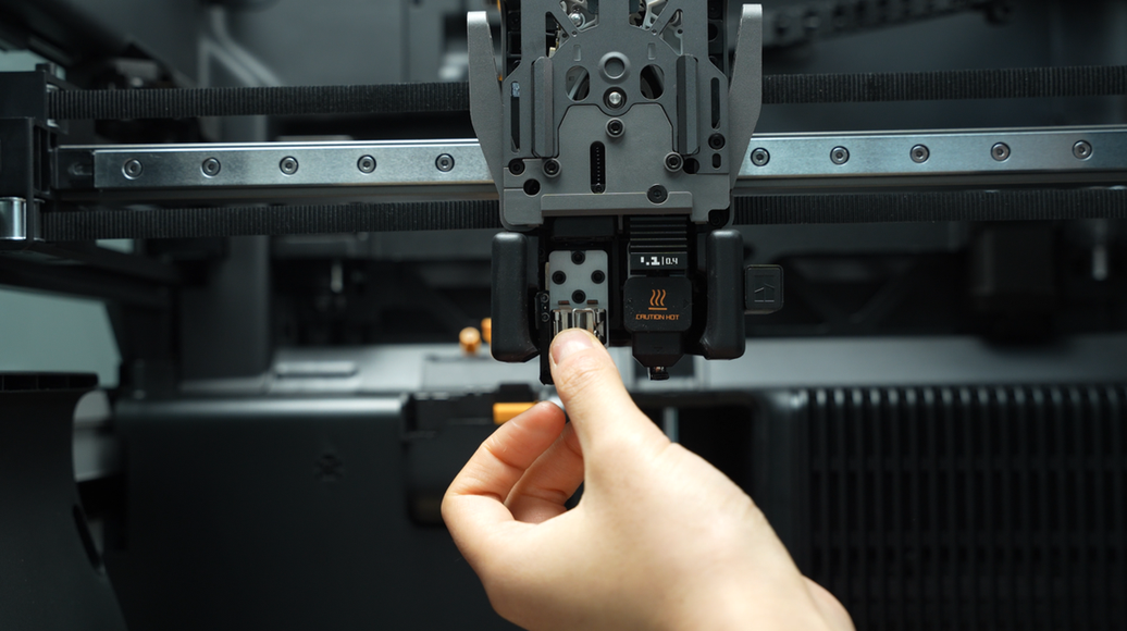
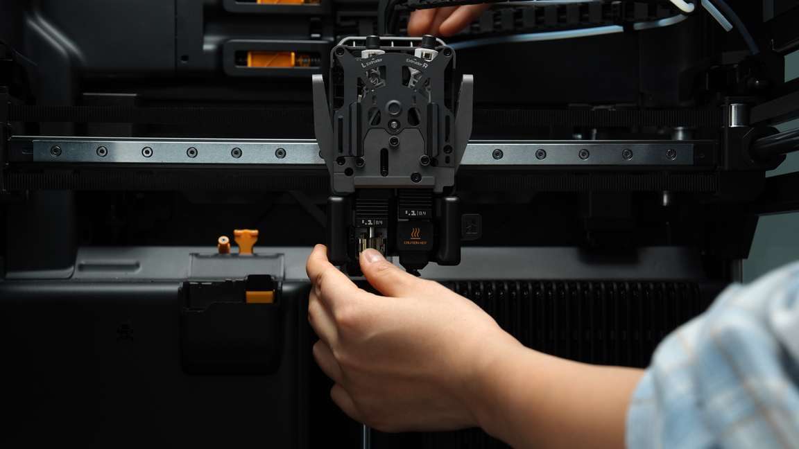
¶ Step 3: Remove the left hotends
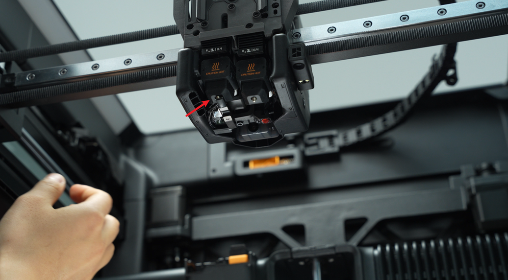
The flow blocker is located on the lift connecting rod, and it moves left and right by toggling the connecting rod.
If you need to remove a hotend but the flow blocker is blocking it, you must first move the flow blocker lever to clear the way before disassembling to prevent accidentally bending the flow blocker while removing the hotend.
During toggling, the flow blocker may not fully move into position due to the tilt limit of the lever. In this case, a rough movement followed by fine adjustment is necessary to ensure the flow blocker is completely in place.
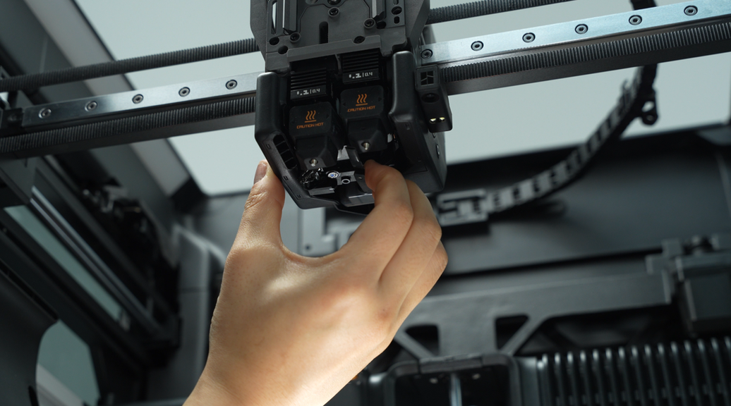
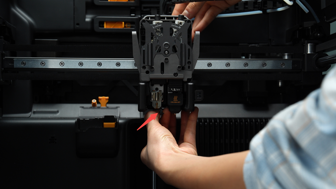
Before starting to remove the hotends, please press the cutters on both sides to cut the filament, making it easier to remove the hotends.
Remove the silicone sock for hotend that is not blocked by the flow blocker, unlock the latch to remove the hotend, and pre-latch the latch of the heating assembly.
¶ Step 4: Remove the extruder filament guide and left cutter
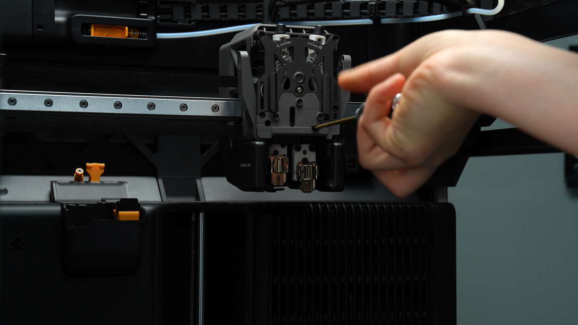
After unscrewing the four screws (M2.5x7 * 3;BT2x6 * 1) on the extruder filament guide, use your fingers to press upward against the black hotend connector while simultaneously pressing down on the left cutter lever to release it slightly from the opening slot near the cutter screw.
Then, exert force outward from the lower right corner of the extruder filament guide to pry it out.
Use your fingers to push upward against the black hotend connector while simultaneously pressing down on the handle of the left cutter. This will allow the left cutter to disengage slightly from the slot near the cutter screw.
Then, pry the front guide cover outward by applying force from the front toward the lower right corner.
The left cutter is located within the extruder filament guide and will be removed together when removing the extruder filament guide.
Please take care to store it properly to prevent loss.
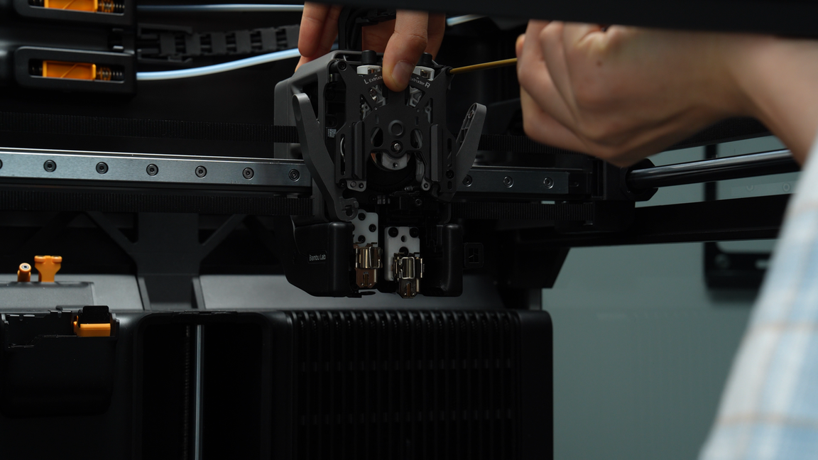
¶ Step 5: Remove the extruder front cover
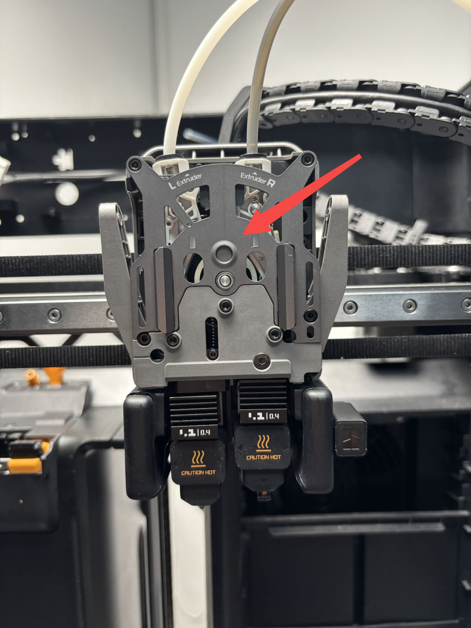
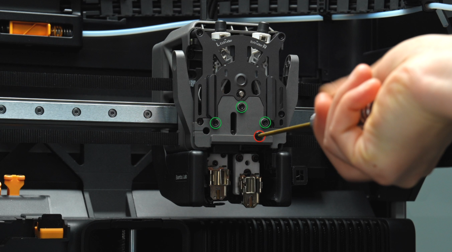
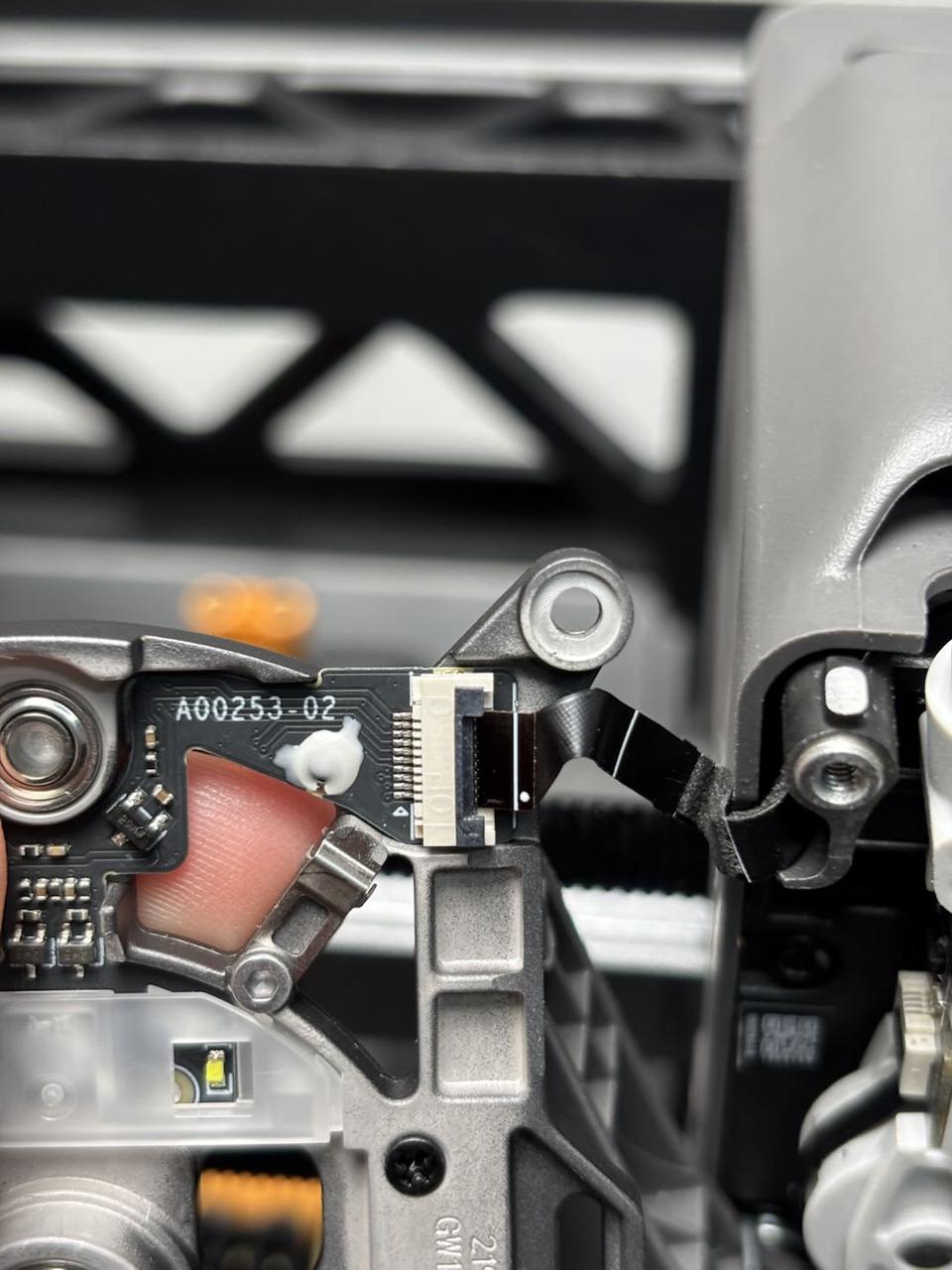
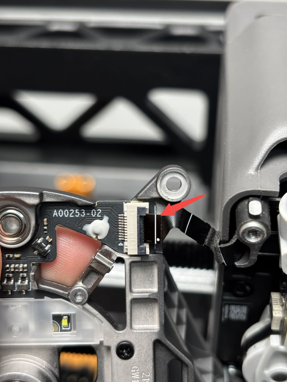
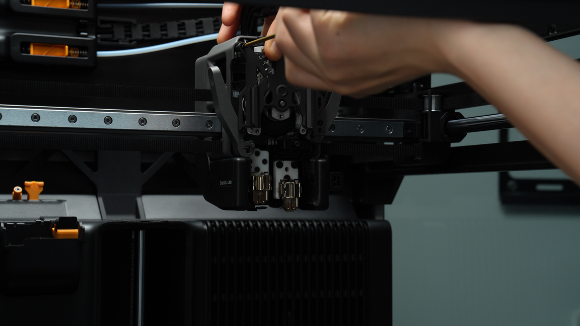
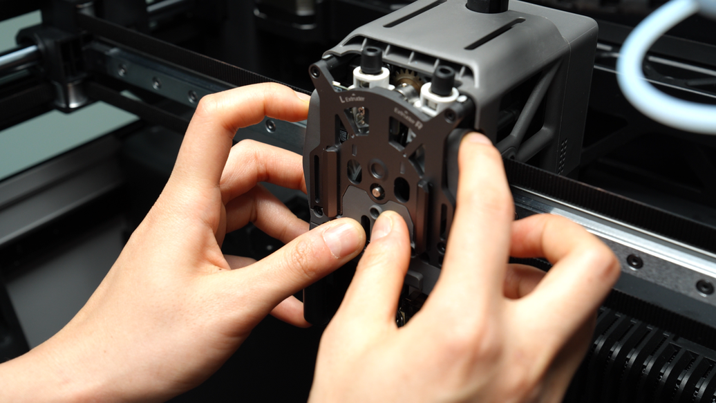
Unscrew the two screws (M2.5x7) on the extruder front cover. Please be careful when removing the extruder front cover to prevent the FPC cable from being torn off.
Next, release the latch on the FPC (flex cable) connector and unplug the front cover Hall sensor cable to remove the extruder front cover.
¶ Assembly Steps
¶ Step 1: Install the extruder front cover
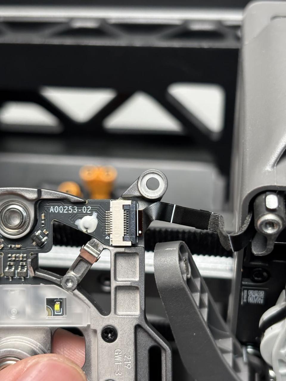
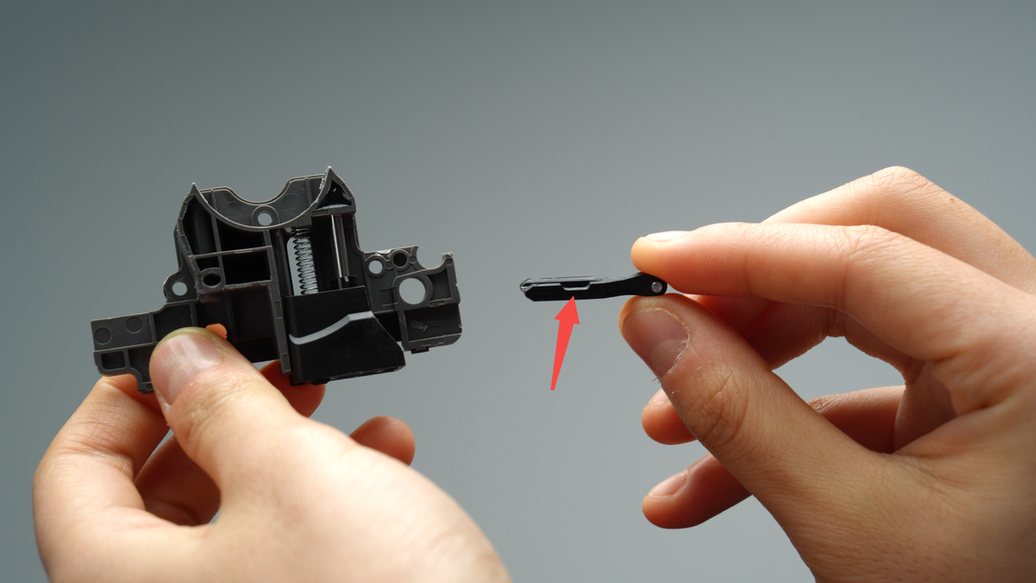
Insert the FPC cable into the extruder front cover connector, ensuring that the head of the FPC cable is fully inserted into the connector before locking it in place. The white line on the FPC cable is in a horizontal position, indicating that the FPC cable is inserted correctly.
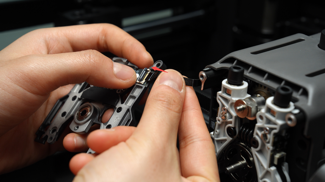
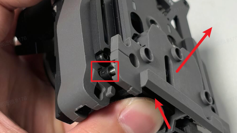
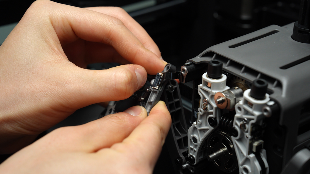
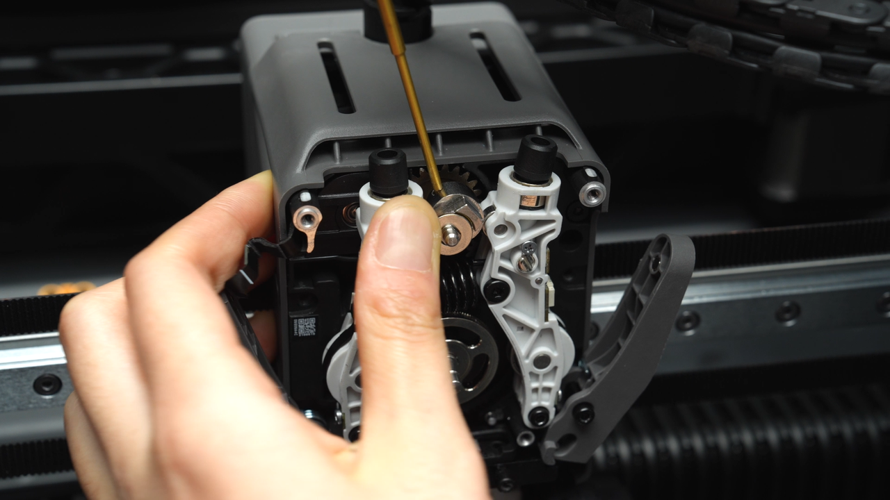
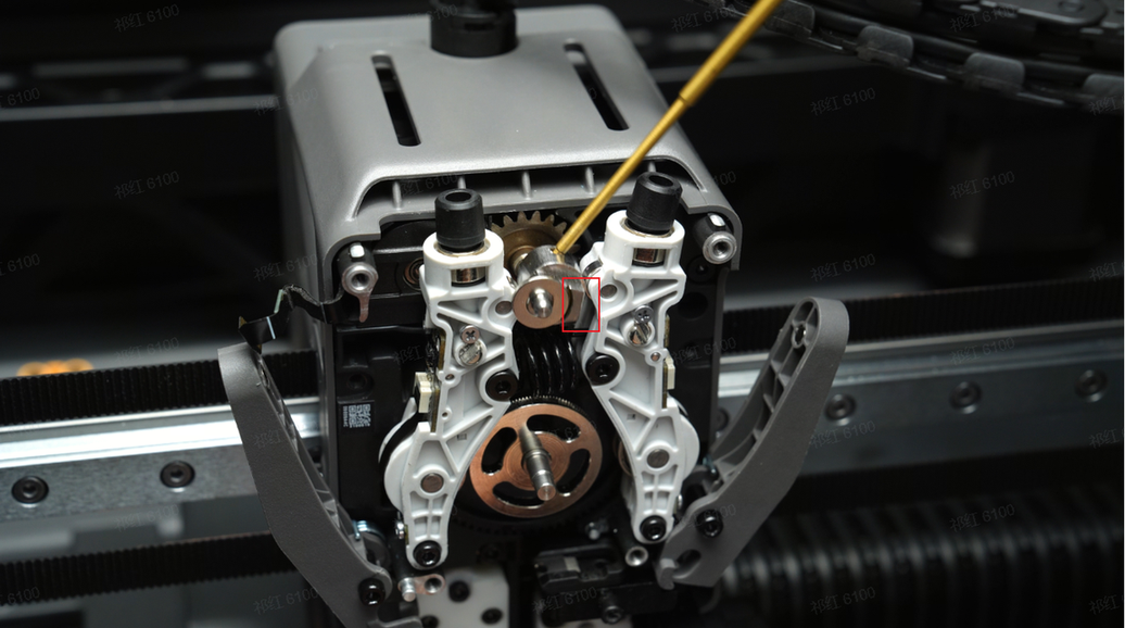
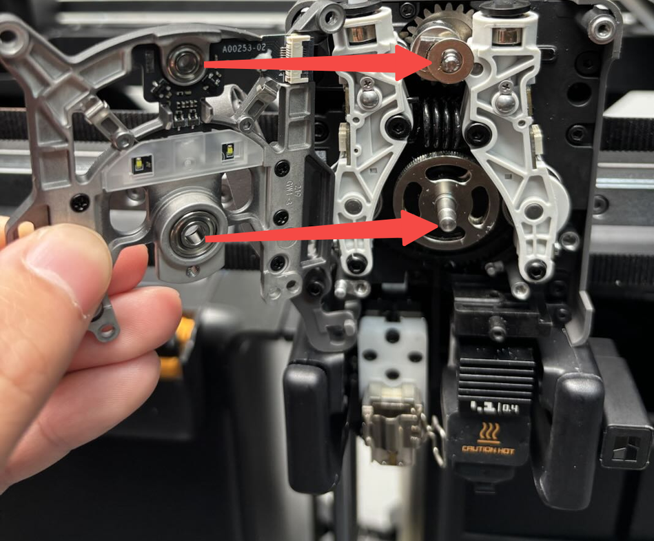
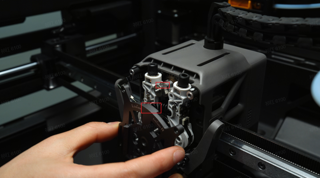
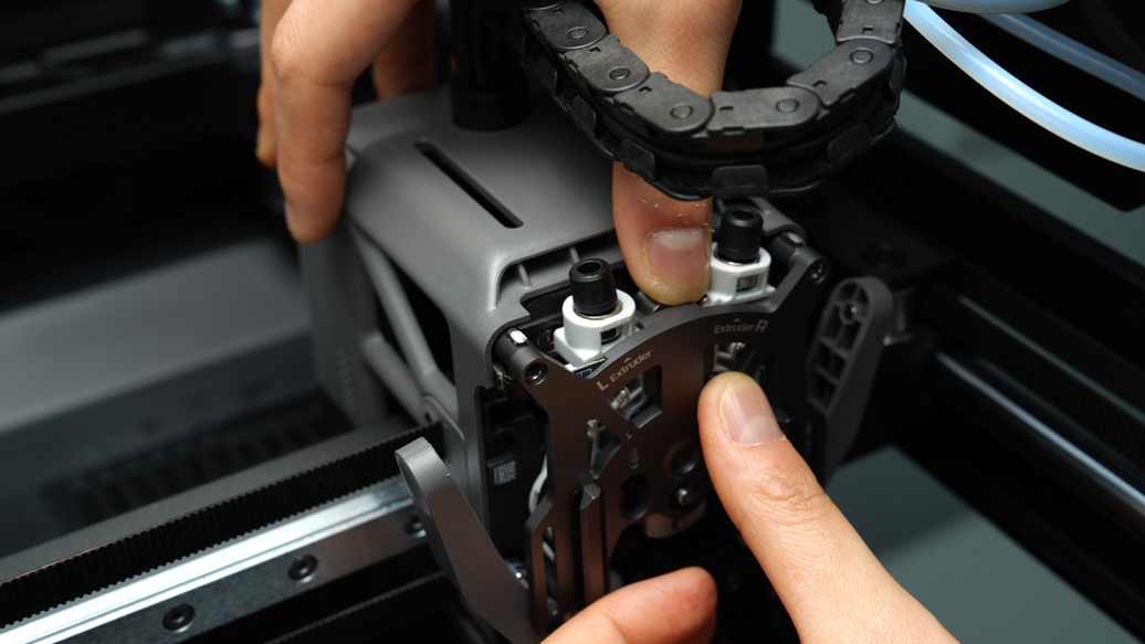
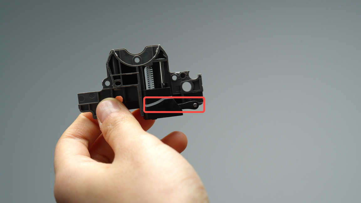
Before installing the extruder front cover, it is necessary to adjust the angle of the extruder switch cam using an Allen key for easier installation later on.Insert the Allen key into the small hole of the cam, hold the left extruder idler with your hand and rotate it until the cam surface is parallel to the extruder idler.
As shown in the red box marking in the figure below at the Angle.
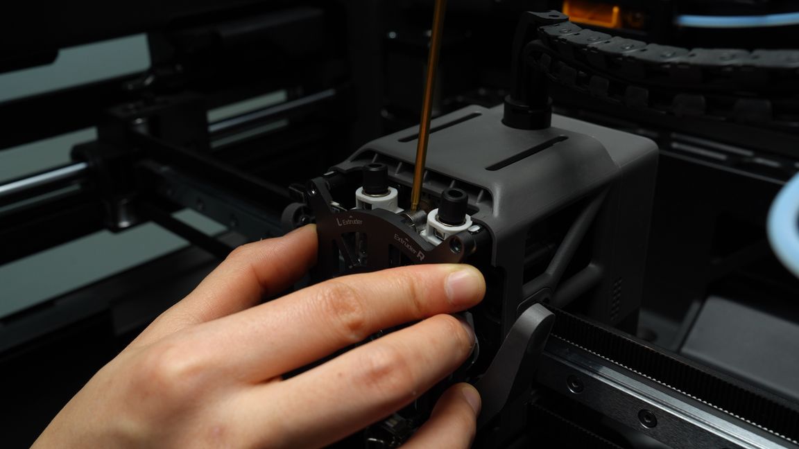
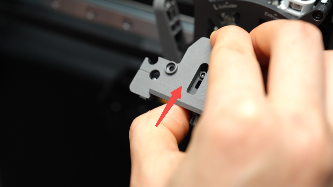
Align the upper and lower bearings of the extruder front cover with the corresponding positions on the extruder, then install the front cover into the extruder.
If the top bearing does not seat properly, gently press down on the cam to help the top bearing snap into place.
Fold the side FPC cable, neatly organize it, and tuck it into the gap on the side of the toolhead.
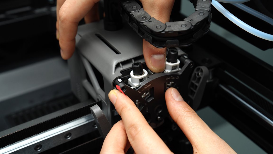
Tighten the two screws (M2.5x7) on the extruder front cover.
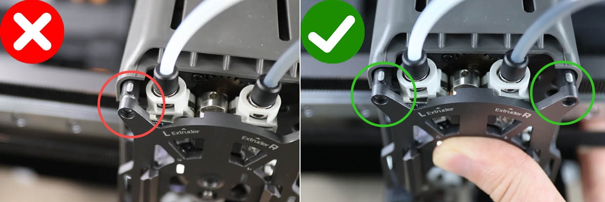
Warning: Before inserting screws, ensure the screw holes on both sides are perfectly aligned!
If one end is still misaligned and forcibly screwed in, it may cause the front cover of the extruder cracked. In the image below, the right shows correctly aligned situation while the left shows misaligned situation.
¶ Step 2: Install the extruder filament guide and the left cutter
The left cutter needs to be installed together with the extruder filament guide.
Ensure that the notch of the left cutter is facing upwards, then place it into the cutting blade slot of the extruder filament guide.
When installing the extruder filament guide, make sure to continuously press upwards against the black hotend connector and simultaneously press the left cutter lever, adjusting it to an appropriate angle for easy insertion.
Then, install the extruder filament guide. Finally, press on both sides of the cutter lever, applying force to completely flatten the front cover.
Then, tighten the four screws (M2.5x7 * 3;BT2x6 * 1) on the extruder filament guide.
¶ Step 3: Install the left hotends
Same as the disassembly process, if you need to install a hotend and the flow blocker is obstructing it, you must first move the flow blocker connecting rod to move the flow blocker aside before proceeding with the installation. This prevents accidentally bending the flow blocker when removing the hotend.
When moving it, the flow blocker may not fully disengage at once due to the lever's tilted position. In such cases, rough movement should be followed by fine adjustments to ensure the flow blocker is completely in place.
Move the flow blocker connecting rod to shift the flow blocker to the other side, then install the left nozzle. Lock the nozzle latch and put on the silicone sock as well.
Please note that when installing the silicone sock on the left hotend, ensure that the sock is not tilted to prevent deformation of the adjacent baffle.
¶ Step 4: Install the toolhead front cover
When reinstalling the front cover of the toolhead, first position it under the extruder and then push it back to secure the front cover in place.
¶ Verify the Functionality
Connect the power and turn on the printer. If no error messages appear, the installation is successful.
¶ End Notes
We hope the detailed guide provided has been helpful and informative.
If this guide does not solve your problem, please submit a technical ticket, we will answer your questions and provide assistance.
If you have any suggestions or feedback on this Wiki, please leave a message in the comment area. Thank you for your support and attention!