¶ Screen
The H2D printer utilizes a 5-inch 1280*720 touch screen for controlling the printer.
The spare parts of the screen include:
-
Screen - Pre-installed hinge * 1
-
Screen connector- No need for replacement if undamaged * 1
-
M2.5x4 screws - Used to fix the hinge and front cover * 2
¶ When to use
- Replace the screen when it goes black, but the screen connector and the lights on the AP board are functioning normally.
¶ Tools and materials needed
-
New screen
-
H2.0 Allen key
-
H1.5 Allen key
Specifications and quantities of screws involved in replacing the H2D screen/screen connector (it is recommended to keep the removed screws properly to avoid loss):
| Specification | Image | Use | Position | Quantity | |
|---|---|---|---|---|---|
| BT2x12 | Fix the front cover |  |
1 | ||
| M2.5x4 | Fix the screen | 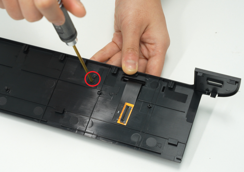 |
2 | ||
| BT2.6x8 | Fix the AP board cover (only involved when replacing the screen connector) |  |
1 |
¶ Safety Warning
IMPORTANT!
It's crucial to power off the printer before conducting any maintenance work, including work on the printer's electronics and tool head wires. Performing tasks with the printer on can result in a short circuit, leading to electronic damage and safety hazards.
During maintenance or troubleshooting, you may need to disassemble parts, including the hotend. This exposes wires and electrical components that could short circuit if they contact each other, other metal, or electronic components while the printer is still on. This can result in damage to the printer's electronics and additional issues.
Therefore, it's crucial to turn off the printer and disconnect it from the power source before conducting any maintenance. This prevents short circuits or damage to the printer's electronics, ensuring safe and effective maintenance. For any concerns or questions about following this guide, we recommend submitting a technical ticket regarding your issue and we will do our best to respond promptly and provide the assistance you need.
¶ Video guide
You can refer to this video for disassembling and installing the front cover
To be added soon
¶ Replace the H2D Screen
¶ Remove the Screen
¶ Step 1:Remove the front cover
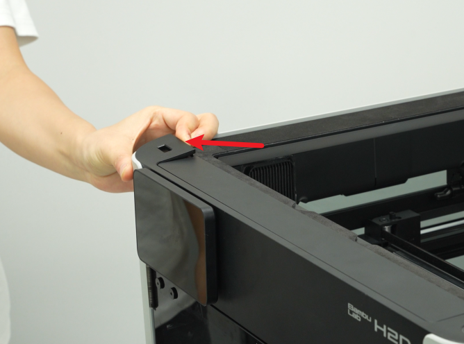
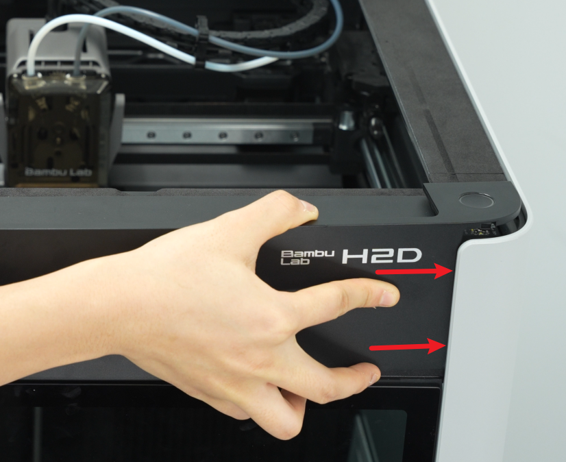
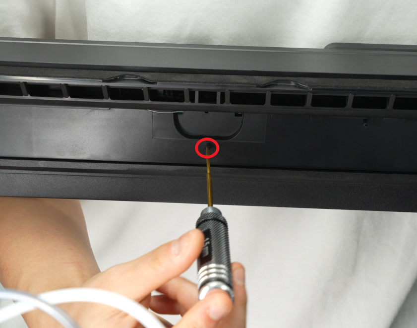
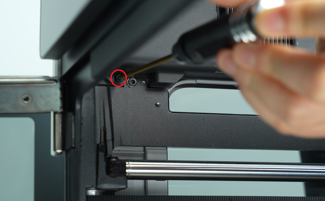
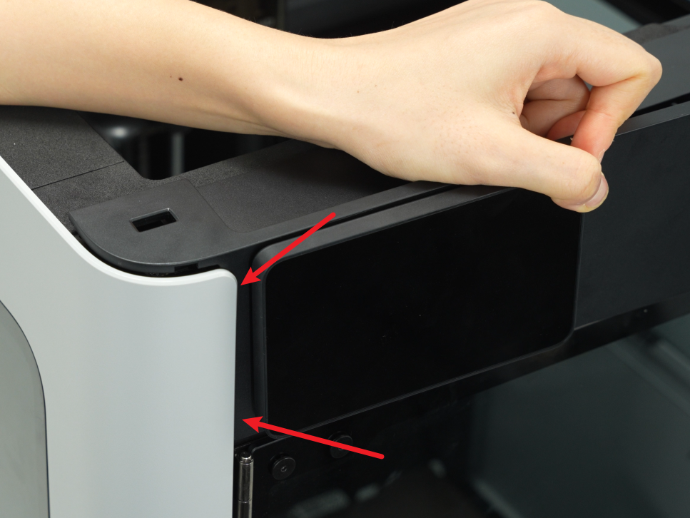
- Use an H1.5 Allen key to remove a fixing screw (BT2×12), then hold the buckle on the left side of the front cover with your hand, snap off the top left side of the front cover, and then snap open the top right side:


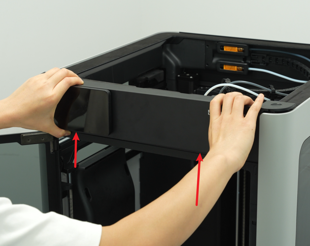
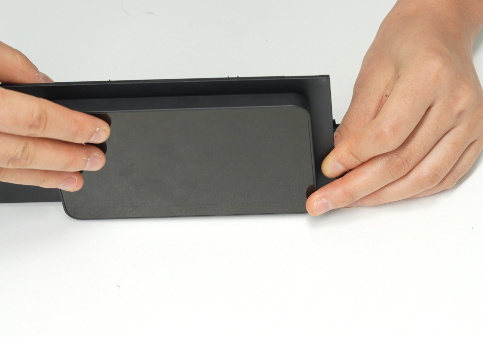
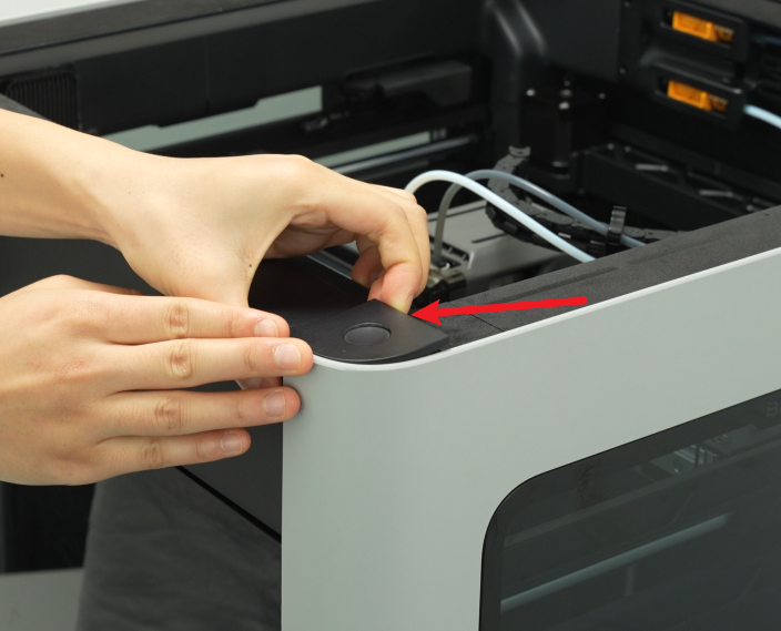
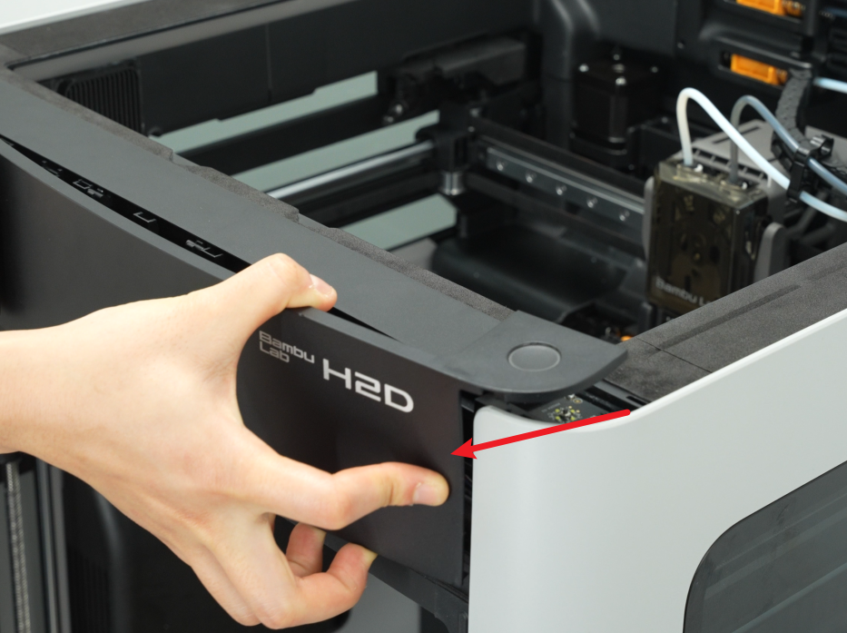
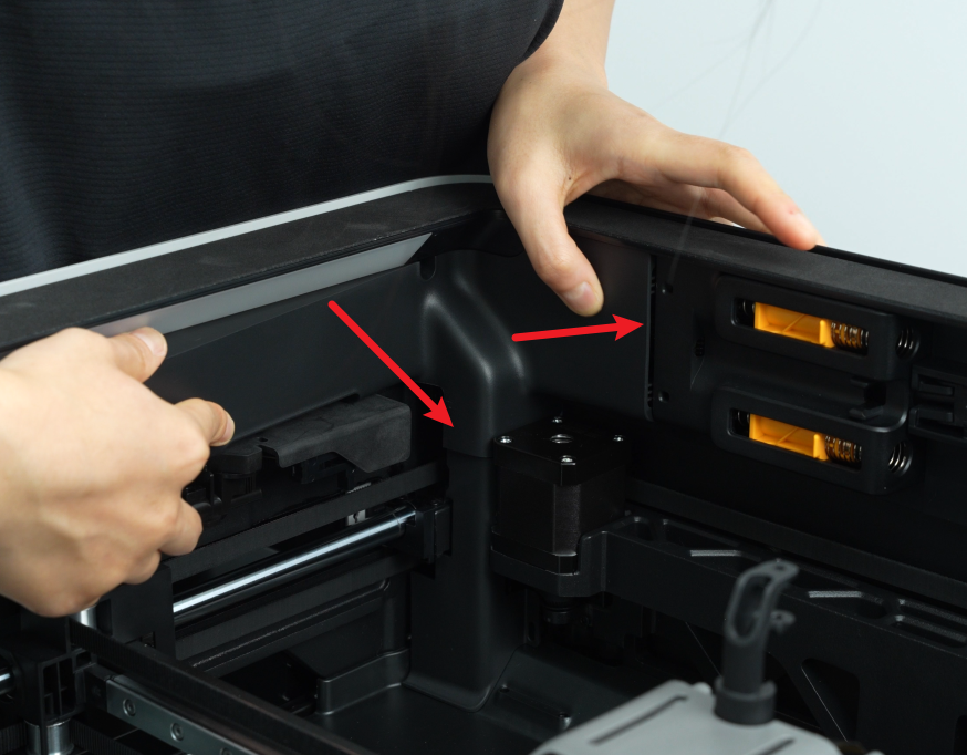
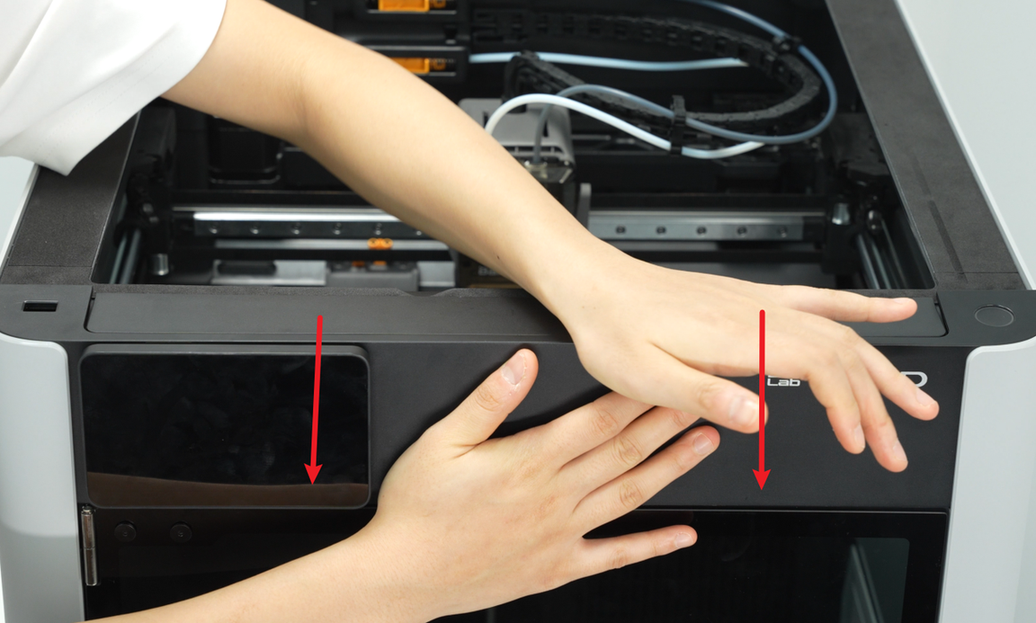
- Then place your thumbs on the bottom of the front cover and push upwards to unlock the front cover card. Then hold the right side of the front cover to bend it slightly and pull the right side of the front cover out from under the right side panel.
Please pull it out carefully to avoid damaging the screen FPC!

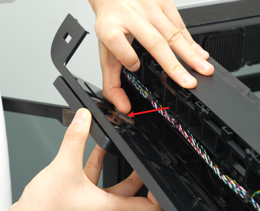
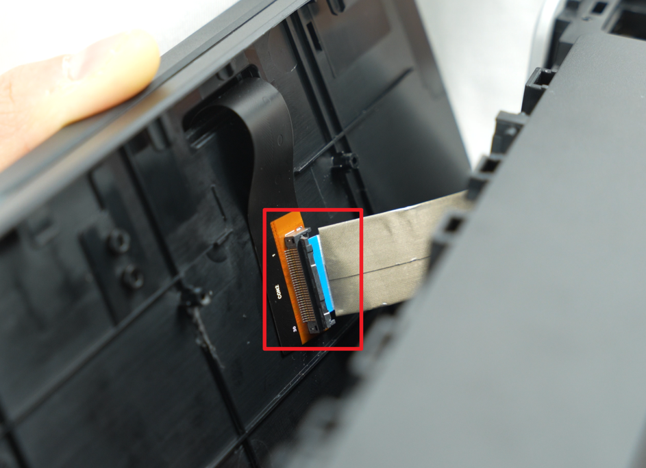
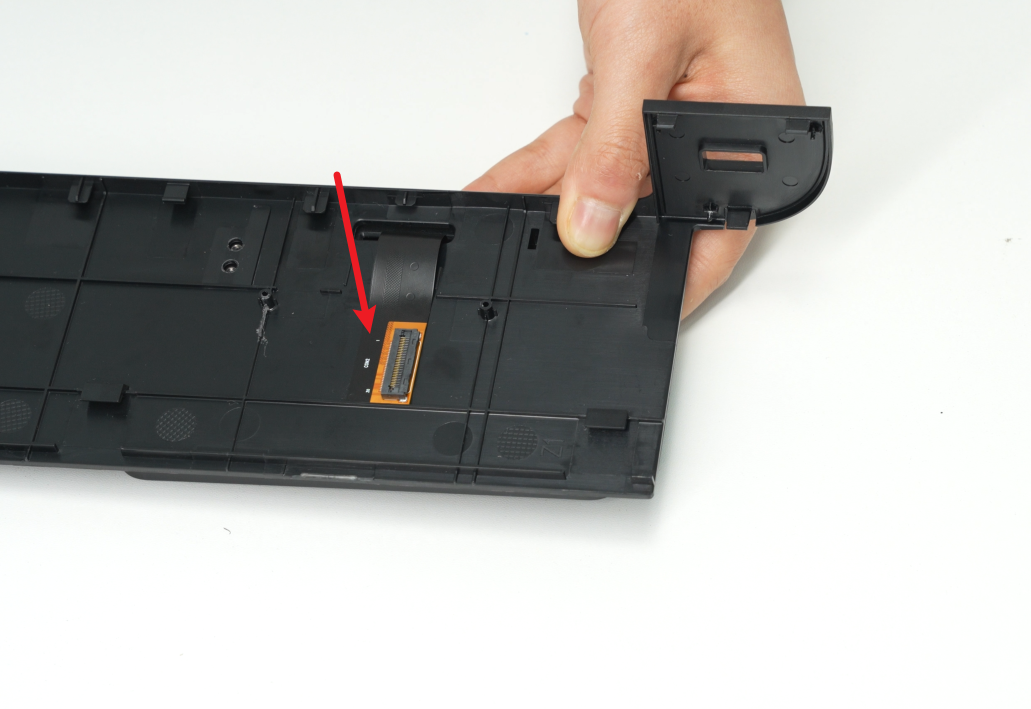
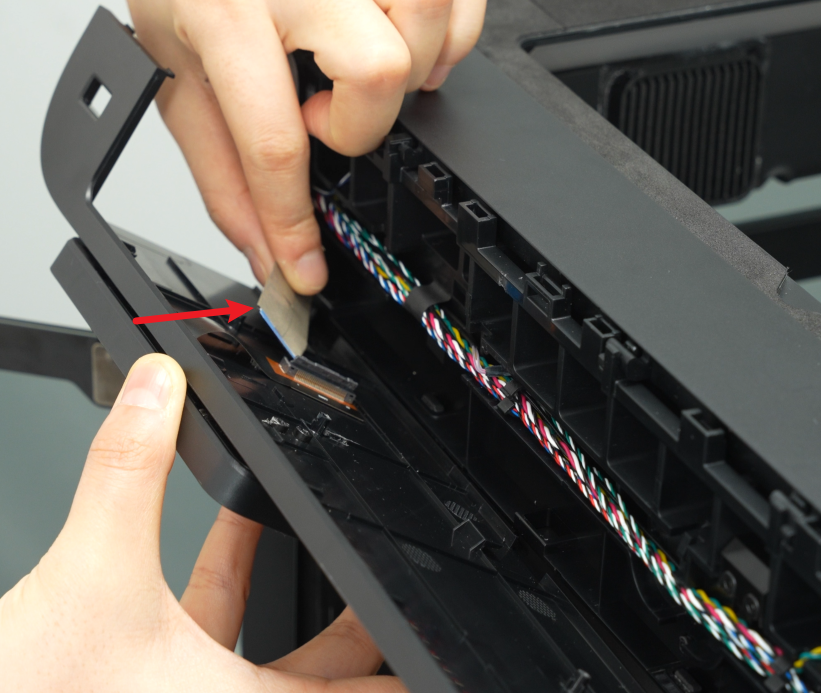
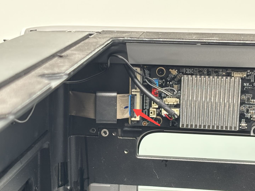
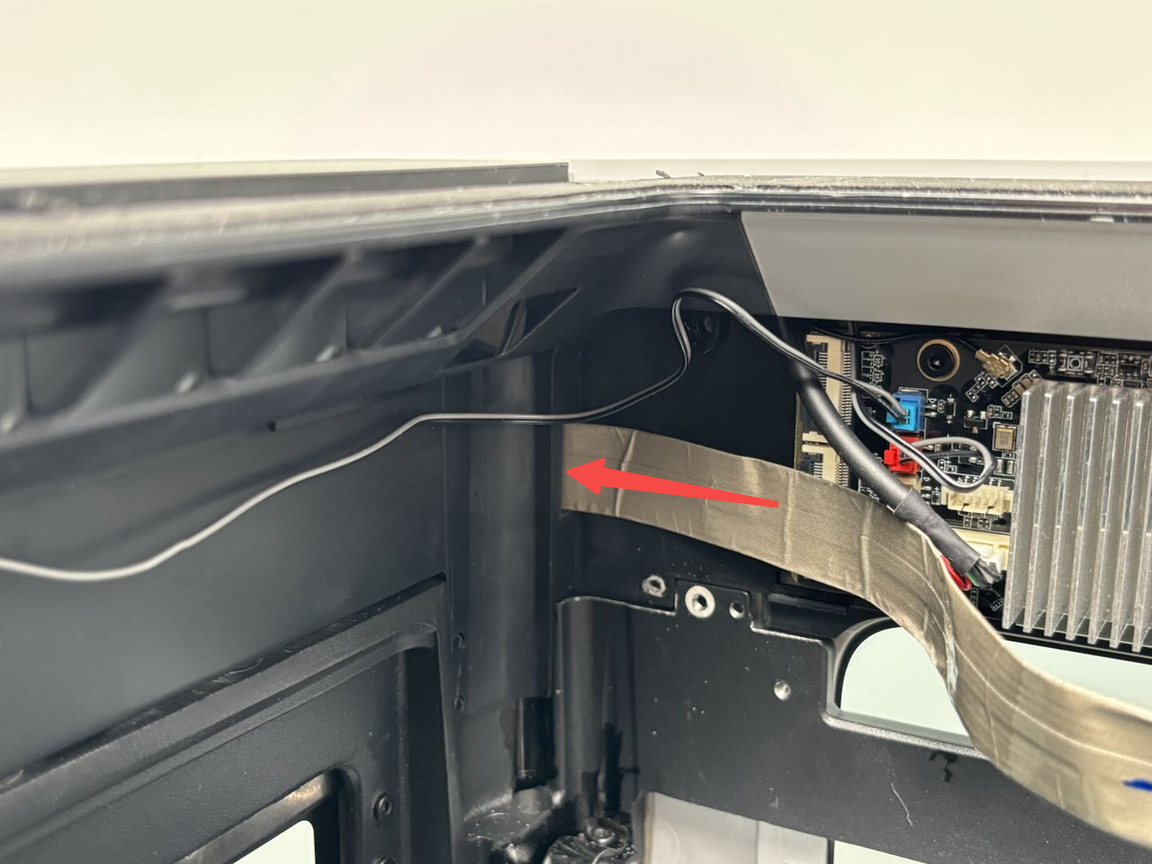
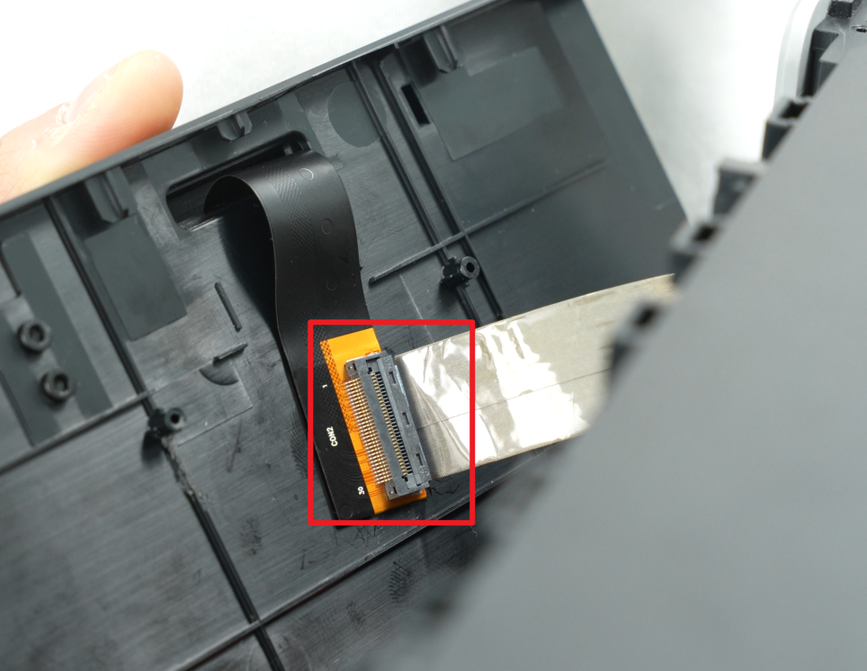
- After pulling the right side of the front cover out of the printer, carefully flip the front cover over to expose the interface between the screen and the screen FPC. Unfasten the buckle of the screen cable upwards, and then remove the screen cable from the buckle.

¶ Step 2: Remove the screen from the front cover
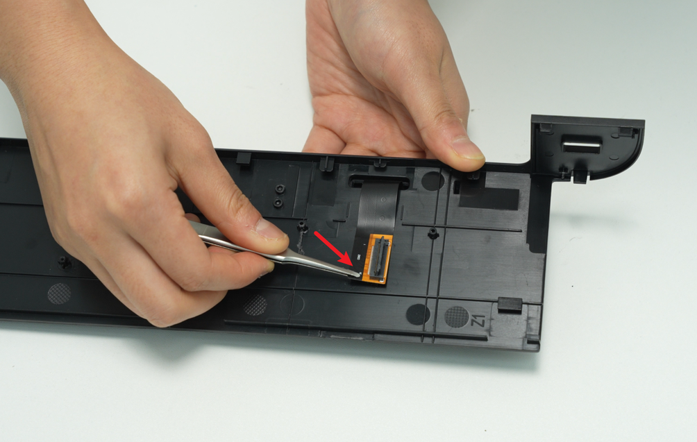
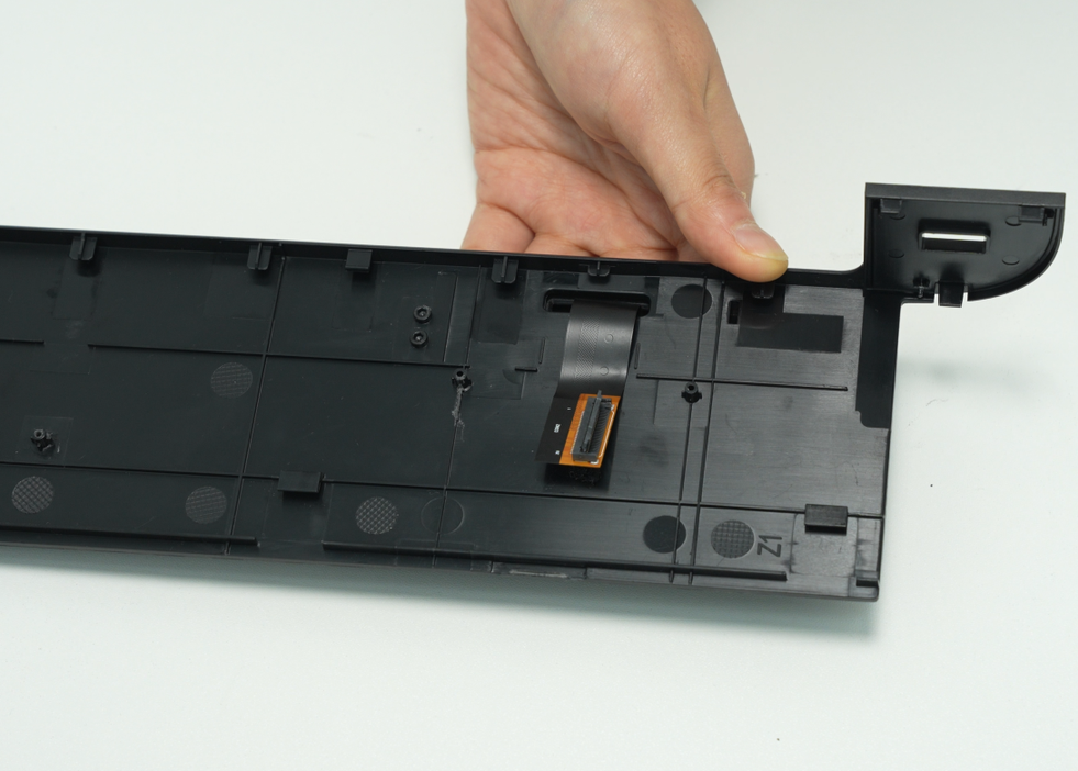
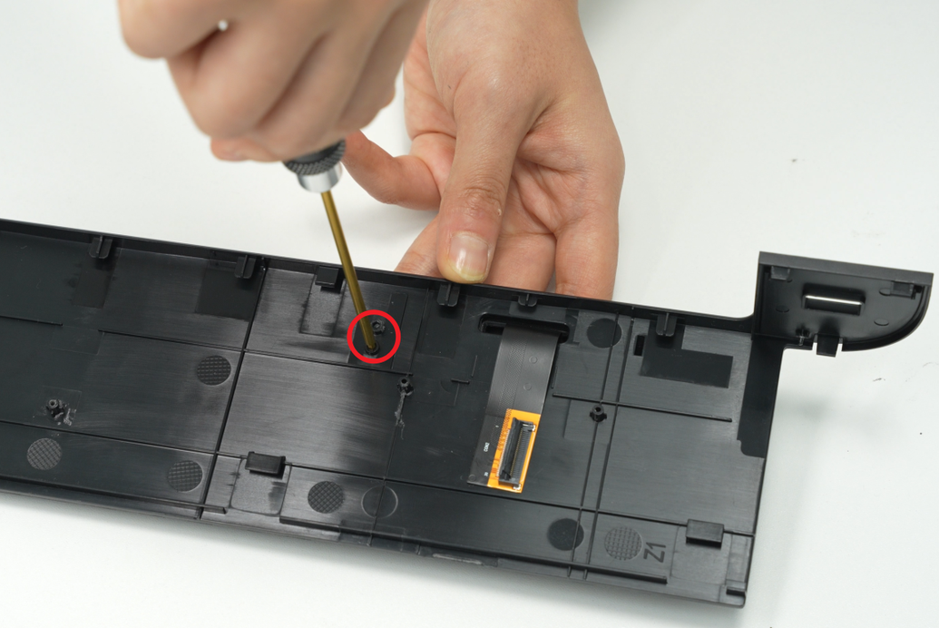
- Place the front cover on the table, use an H2.0 Allen key to remove the two screen hinge fixing screws (M2.5x4), and then tear off the screen FPC from the front cover (you can use tweezers to help tear it off);

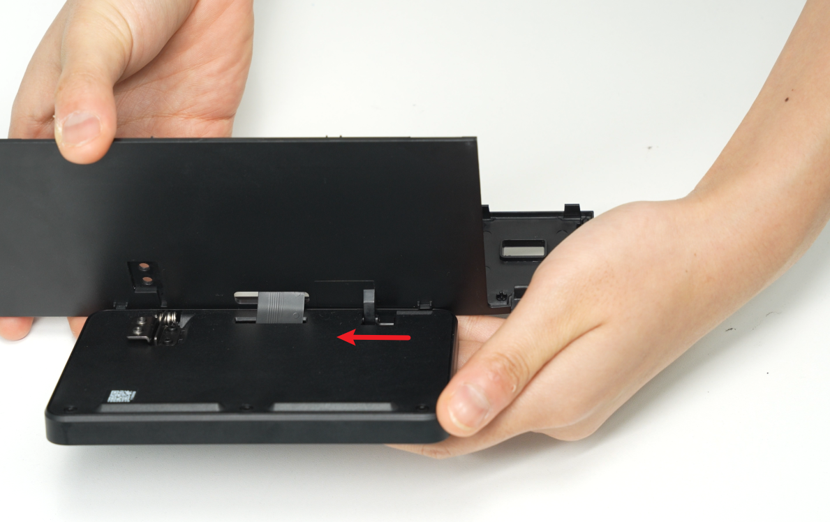
- Hold the front cover, tilt it upwards, pull the screen pins out of the front cover, and remove the screen.
¶ Install the Screen
¶ Step 1: Mount the screen onto the front cover
- First, thread the screen FPC through the small hole in the front cover. Align the screen pins with the small holes on the front cover and insert them.
- Secure the front cover onto the screen by aligning the screw holes. Tighten the two securing screws (M2.5x4) using the H2.0 Allen key. Finally, adhere the FPC to the front cover.
If the original adhesive is insufficient, use double-sided tape.
¶ Step 2: Install the front cover
- Position the left side of the front cover near the printer’s left side. Insert the screen FPC into the connector and fasten the black clasp.


- Hold the right side of the front cover and gently bend it, then insert it into the printer. Press the front cover down to ensure all snaps are secured.


- Finally, use the H1.5 Allen key to tighten one fixing screw (BT2x12).

¶ Replace the H2D Screen Connector
If the screen connector is not damaged, replacement is unnecessary!
¶ Remove the Screen Connector
¶ Step 1: Remove the front cover
- Use the H1.5 Allen key to remove one fixing screw (BT2×12). Hold the snap on the left side of the front cover and detach the top left side, followed by the top right side.

- Then place your thumbs on the bottom of the front cover and push upwards to unlock the front cover card. Then hold the right side of the front cover to bend it slightly and pull the right side of the front cover out from under the right side panel.
Please pull it out carefully to avoid damaging the screen FPC!

- After pulling the right side of the front cover out of the printer, carefully flip the front cover over to expose the interface between the screen and the screen FPC. Unfasten the buckle of the screen cable upwards, and then remove the screen cable from the buckle.


¶ Step 2: Remove the AP Board Cover
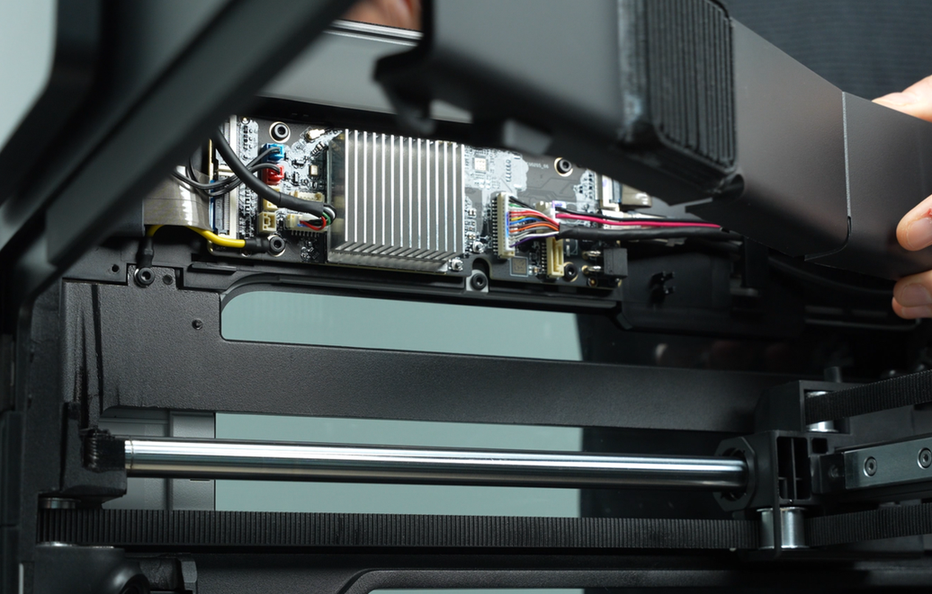
Use the H2.0 Allen key to remove one AP board cover fixing screw (BT2.6×8), then remove the AP board cover from the side near the front door.
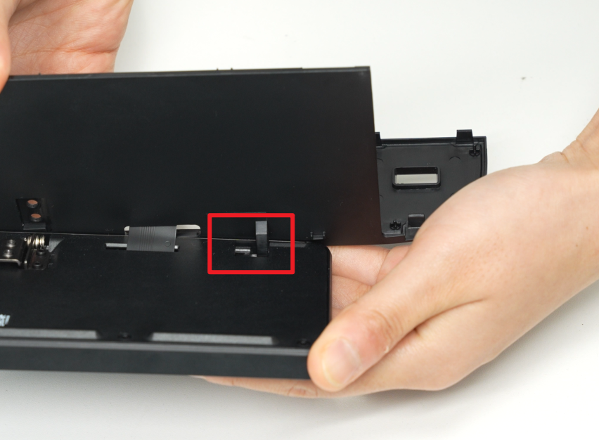
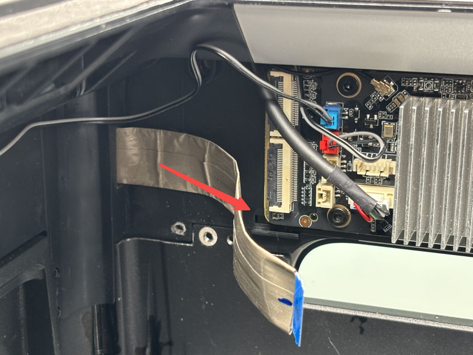
¶ Step 3: Remove the Screen Connector
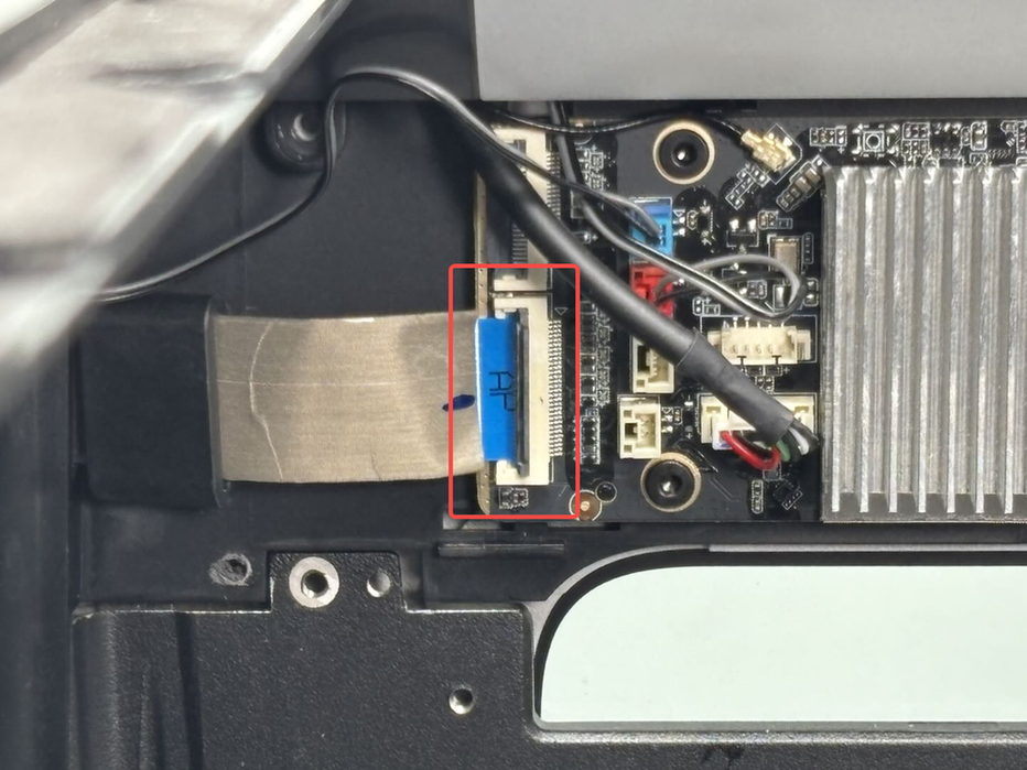
Unfasten the clasp on the screen connector from the AP board. First, remove the magnetic ring from the screen connector, then pull out the screen connector.


¶ Install the Screen Connector
¶ Step 1: Install the screen connector
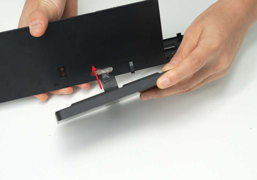
Pay attention to the orientation of the screen connector. The end marked "AP" connects to the AP board:
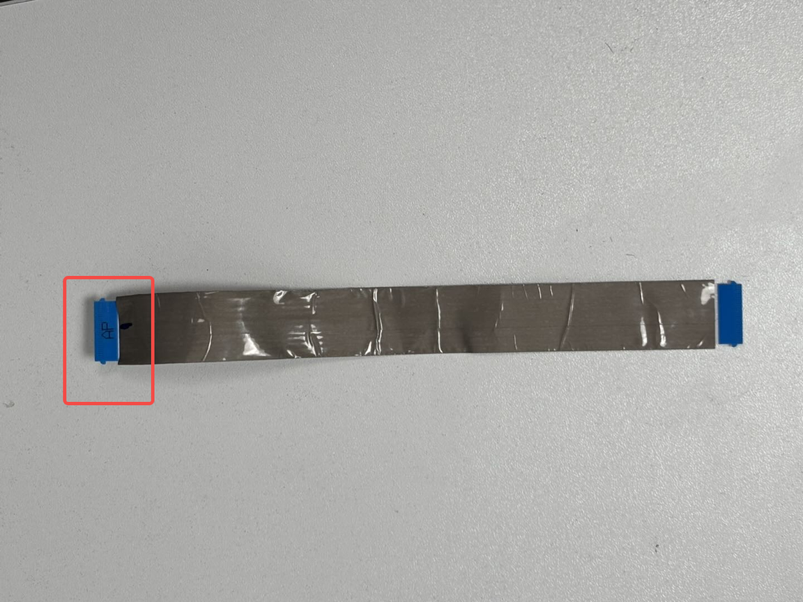
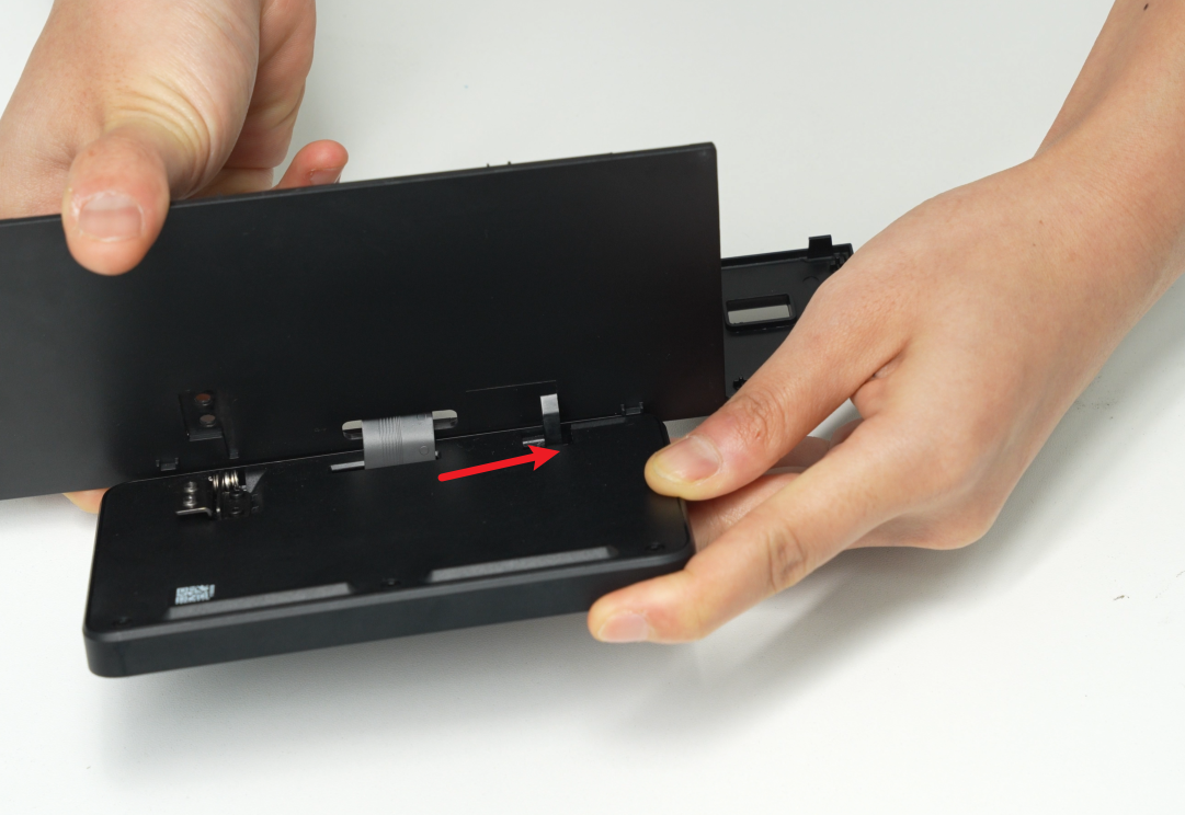
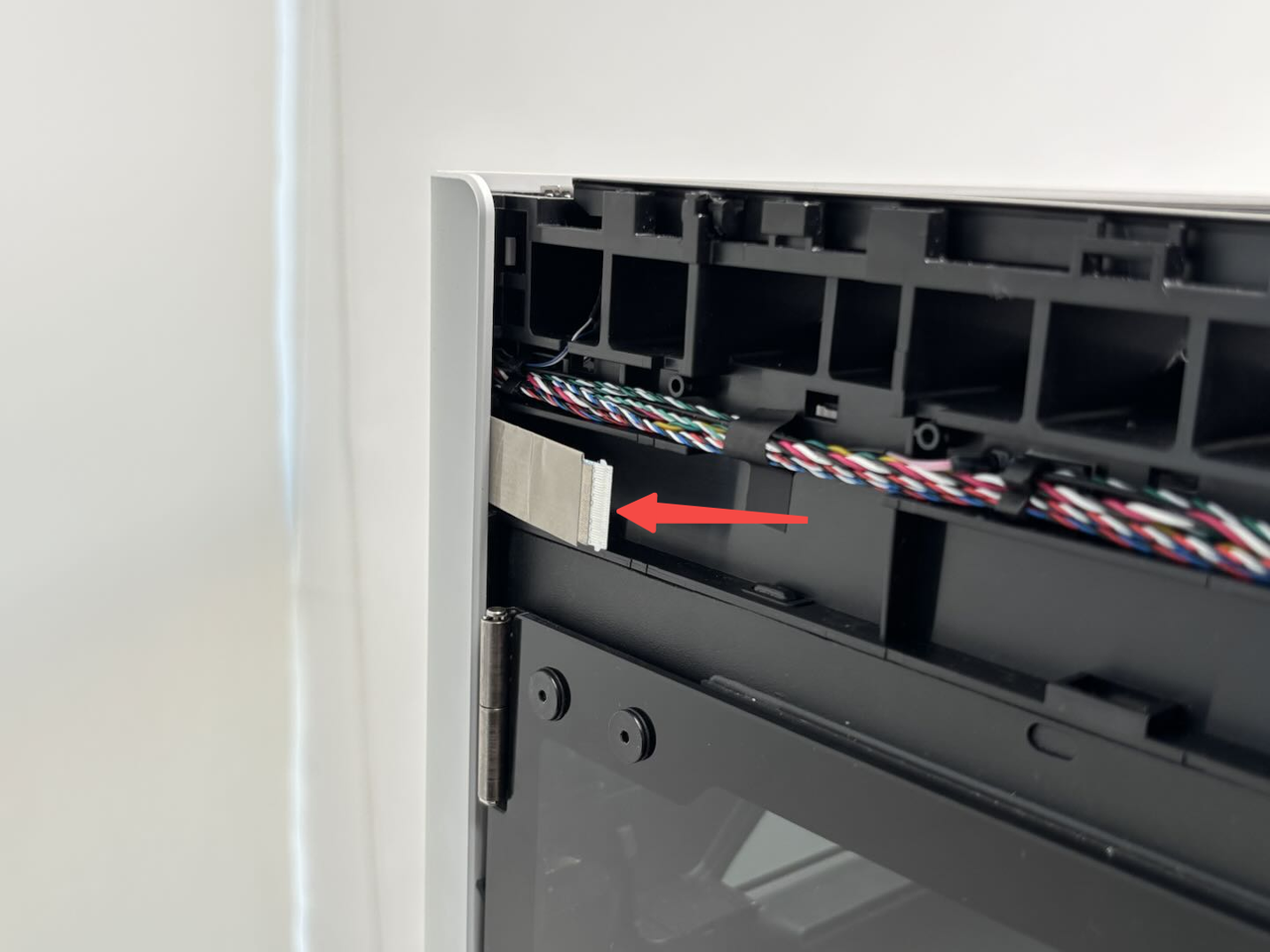
- Ensure the blue side of both ends of the screen connector faces you. Insert the end without "AP" into the small hole on the printer and push it through until the connector is visible from the front.
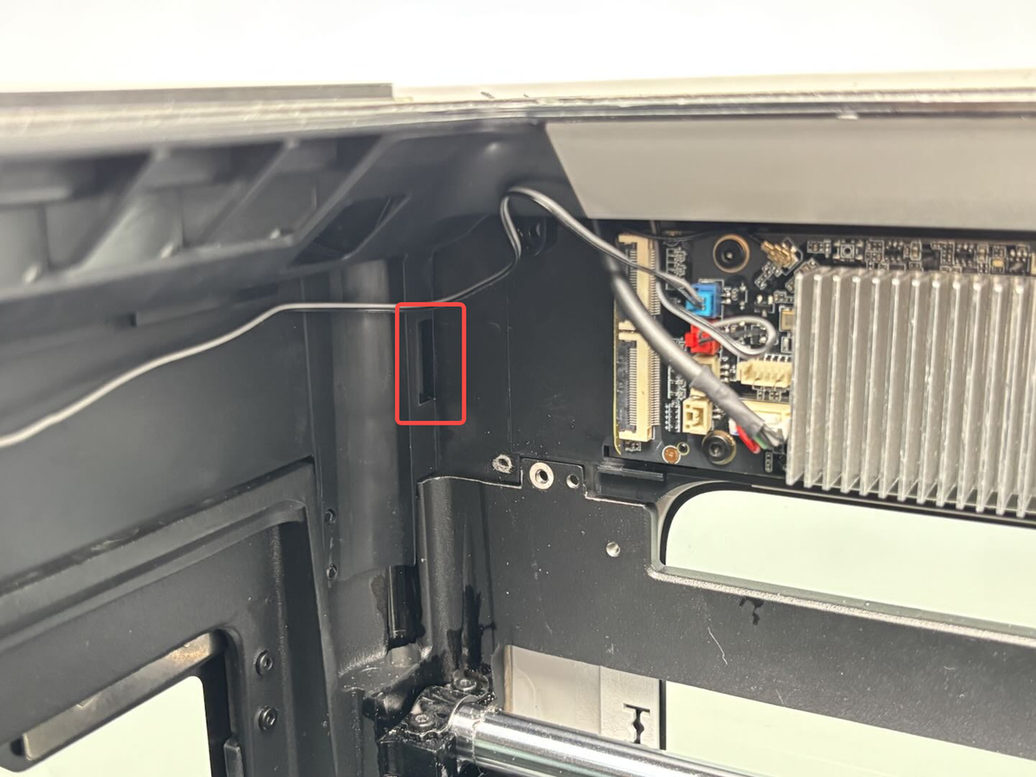
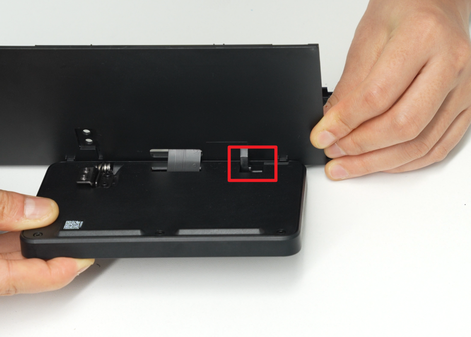
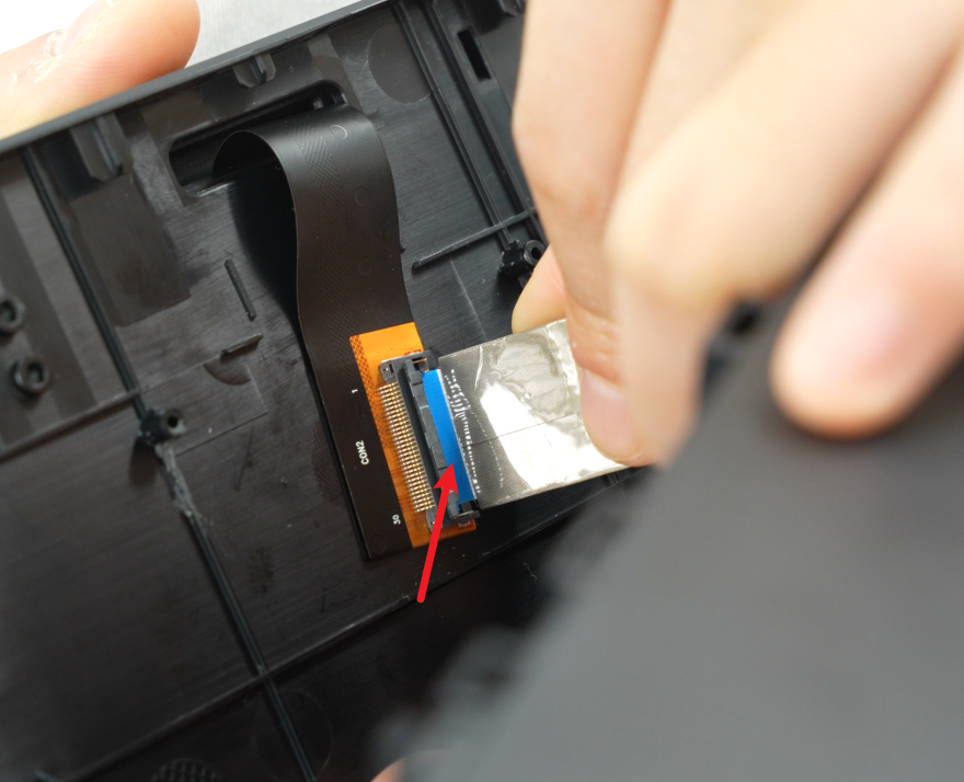
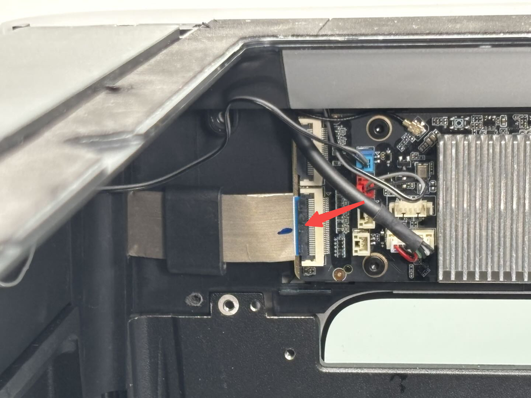
- Slide the magnetic ring onto the screen connector, insert the cable into the AP board interface, and fasten the clasp.
Note: Ensure the end marked "AP" is connected to the AP board.

¶ Step 2: Install the AP Board Cover
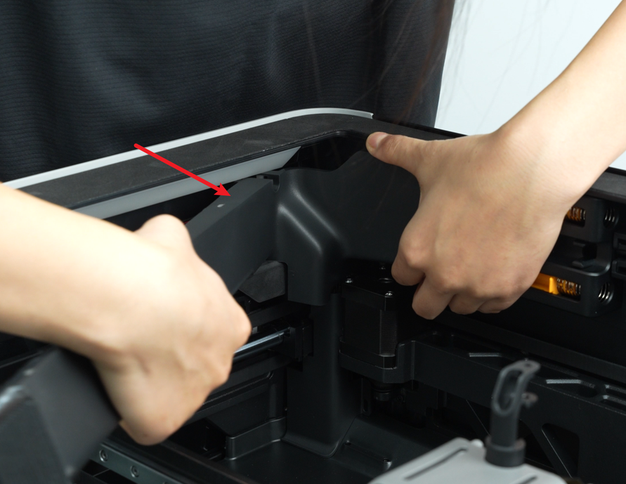
First, reattach the AP board cover from the side near the printer’s rear. Press the two indicated areas firmly into place, ensuring the right side aligns with the filament buffer and the bottom aligns with the cable guard. Tighten one securing screw (BT2.6x8) using the H2.0 Allen key.

¶ Step 3: Install the Front Cover/Screen
- Position the left side of the front cover near the printer’s left side. Insert the screen FPC into the connector and fasten the black clasp.

- Hold the right side of the front cover and gently bend it, then insert it into the printer. Press the front cover down to ensure all snaps are secured.

- Finally, use the H1.5 Allen key to tighten one fixing screw (BT2x12).

¶ Verify the Functionality
Turn on the printer. If the LCD screen lights up and displays normal, and the touch screen functions normally, the replacement is complete.
Otherwise, check the connector again and try again. If it still doesn't work, please contact Bambu Lab Technical Support for further assistance.
¶ End Notes
We hope the detailed guide provided has been helpful and informative.
If this guide does not solve your problem, please submit a technical ticket, we will answer your questions and provide assistance.
If you have any suggestions or feedback on this Wiki, please leave a message in the comment area. Thank you for your support and attention!