¶ Tool head with X-Axis assembly
This wiki provides guidance and precautions for replacing the H2D tool head with X-Axis assembly, excluding the disassembly and assembly of the tool head itself.
¶ When to replace
The Tool head with X-Axis assembly is damaged or not working as expected
¶ Tools and materials needed
-
The new tool head with X-Axis assembly
-
H1.5 & H2.0 Allen key
-
Short Allen key & L-shaped Allen key
-
Tweezer
¶ Safety Warning
IMPORTANT!
It's crucial to power off the printer before performing any maintenance work on the printer and its electronics, including toolhead wires, because leaving the printer on while conducting such tasks can cause a short circuit, which can lead to additional electrical damage and safety hazards.
When you perform maintenance or troubleshooting on the printer, you may be required to disassemble some parts, including the hotend. This process can expose wires and electrical components that could potentially short circuit if they come into contact with each other or with other metal or electrical components while the printer is still on. This can damage the electronics of the printer and cause further damage.
Therefore, it's essential to power off the printer and disconnect it from the power source before doing any maintenance work. This will prevent any short circuits or damage to the printer's electronics. By doing so, you can avoid potential damage to the printer's electronic components and ensure that the maintenance work is performed safely and effectively.
If you have any concerns or questions about following this guide, open a new ticket in our Support Page and we will do our best to respond promptly and provide you with the assistance you need.
¶ Video Guide
¶ Disassembly Guide
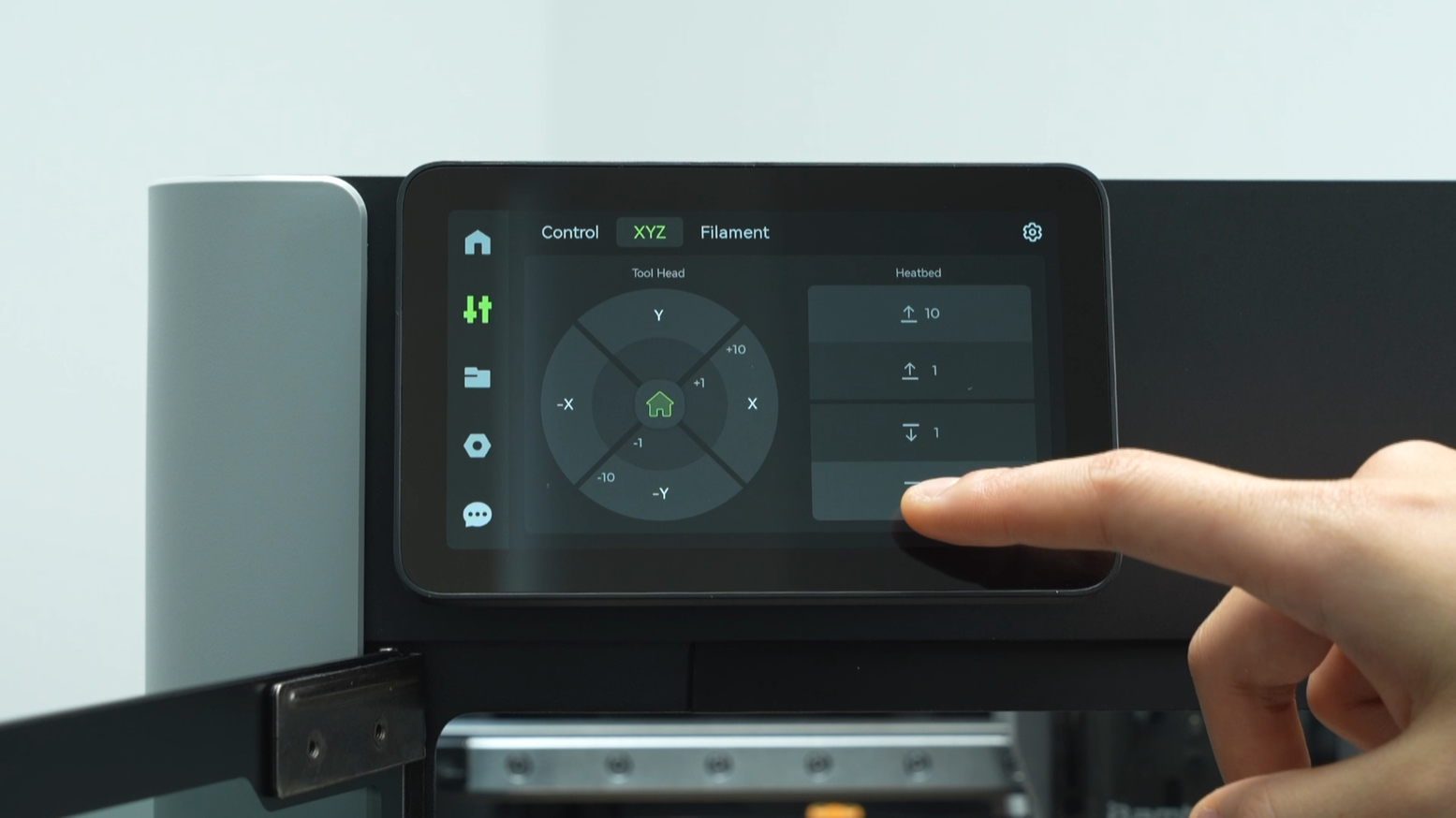
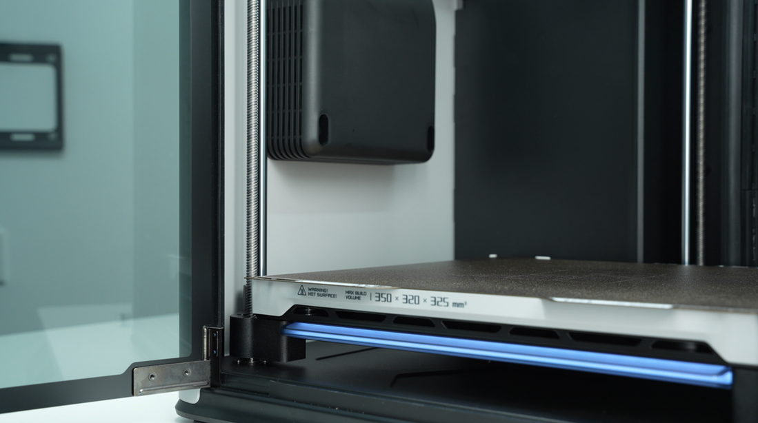
¶ Step 1:Lower the heatbed
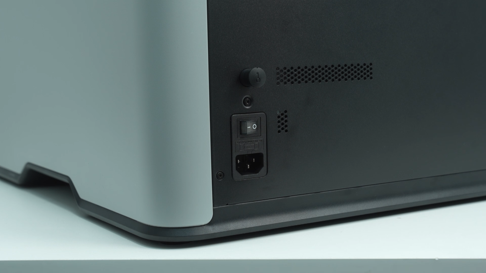
Lower the heatbed on the screen and ensure that the hotend is at room temperature, then power off the printer.
 |
 |
 |
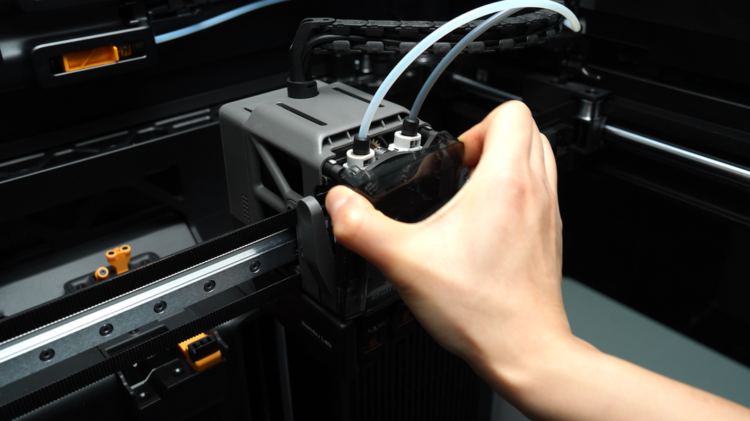
¶ Step 2: Remove the PTFE tube and the toolhead front cover
Pinch the top two corners of the toolhead front cover and lift upwards to remove the front cover.
In a symmetrical manner, press down on the black outer ring to unlock the two connectors on the extruder, releasing the PTFE tube.
 |
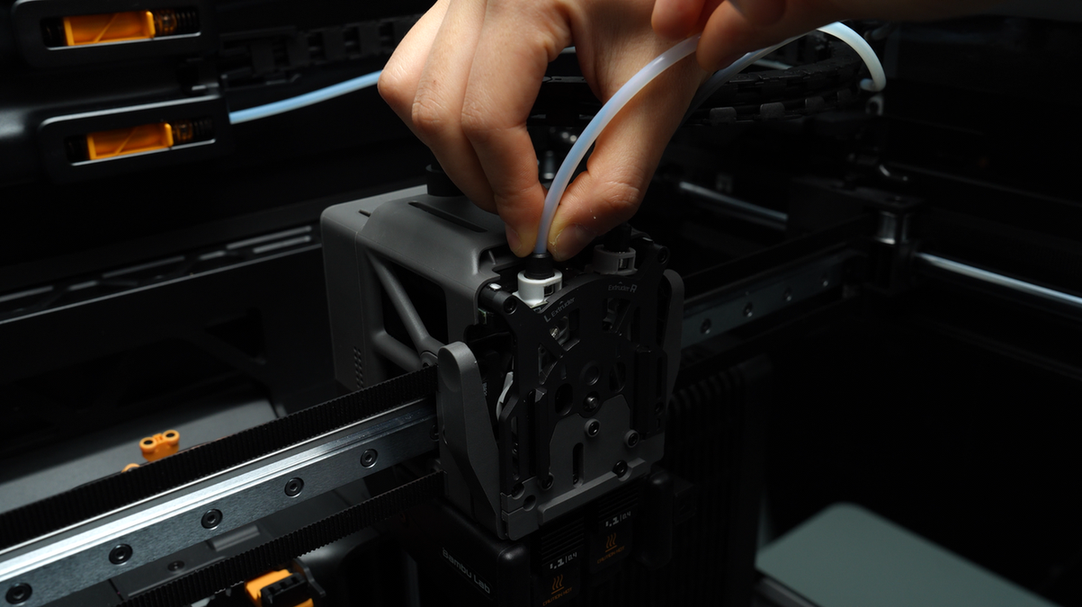 |
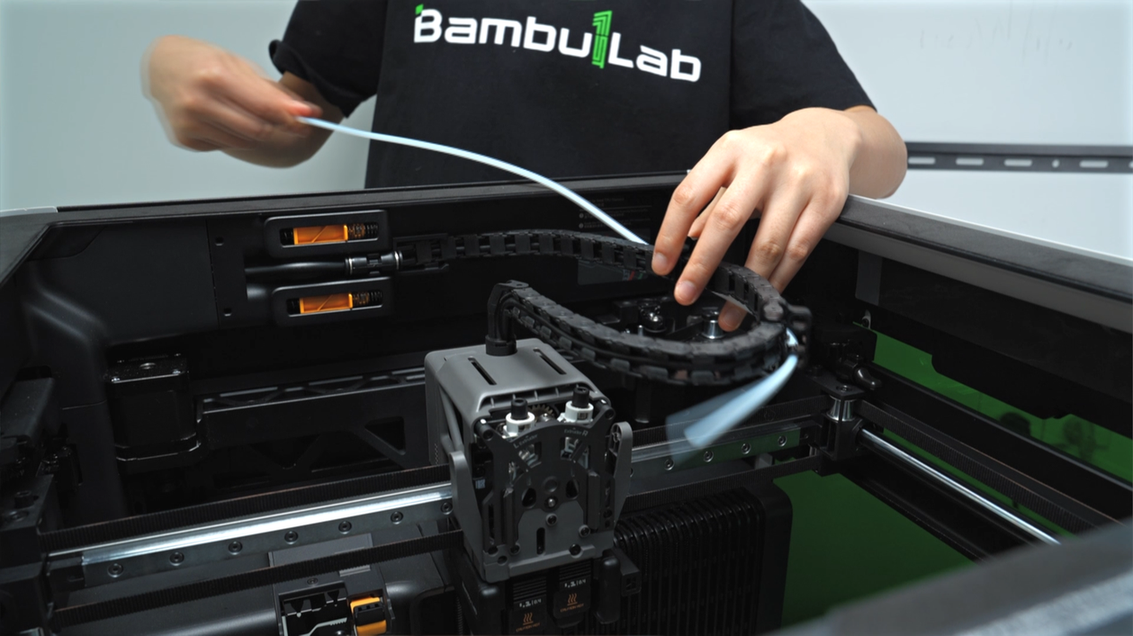
In the same way, press down on the black outer ring to unlock the two pneumatic connectors on the buffer side. Pull out the two PTFE tubes from the cable chain and store them securely.
 |
 |
 |
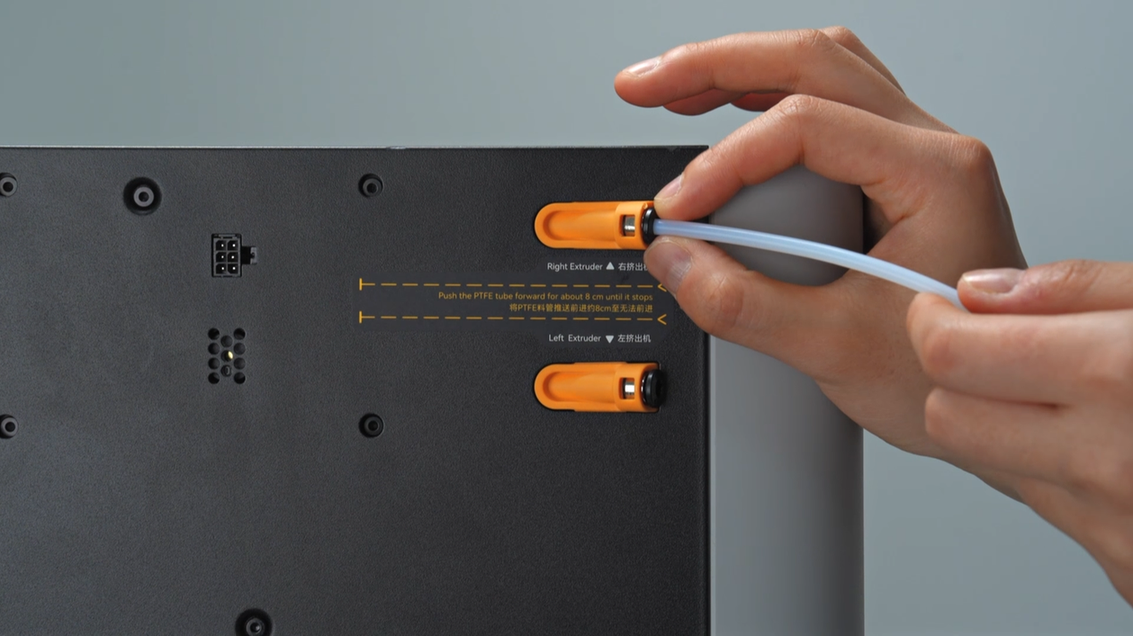
Next, unlock the pneumatic connector at the feed coupler on the back of the printer and remove the PTFE tube.
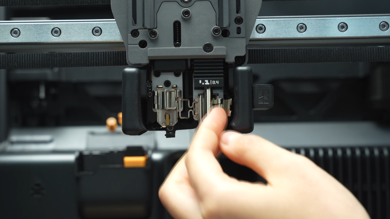
¶ Step 3: Remove the left and right hotends
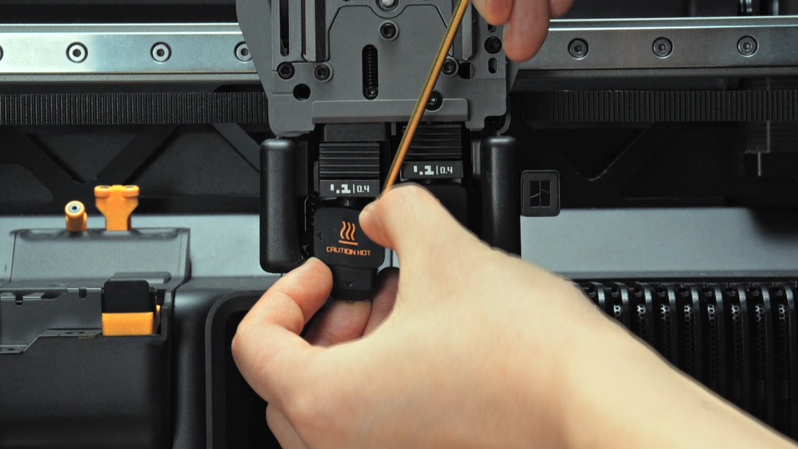
Use an allen key to assist in removing the silicone sock for the hotend that is not blocked by the flow blocker, unlock the latch to remove the hotend, and pre-latch the latch of the heating assembly.
 |
 |
 |
 |
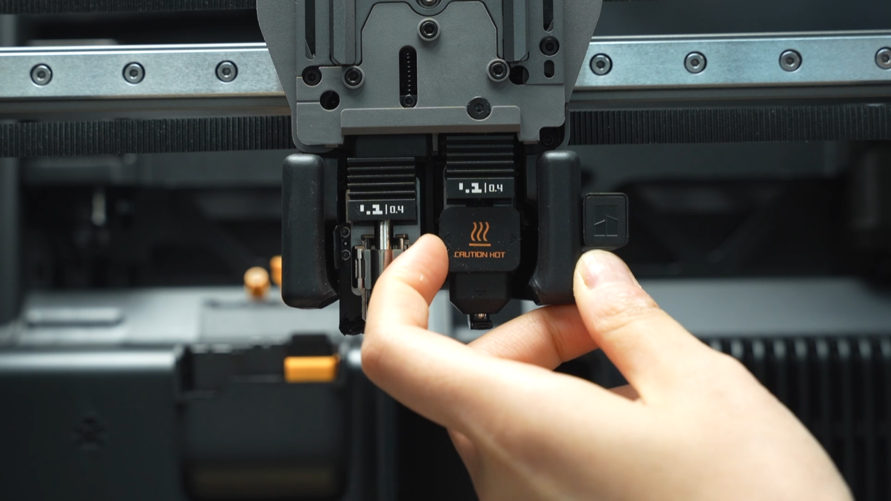
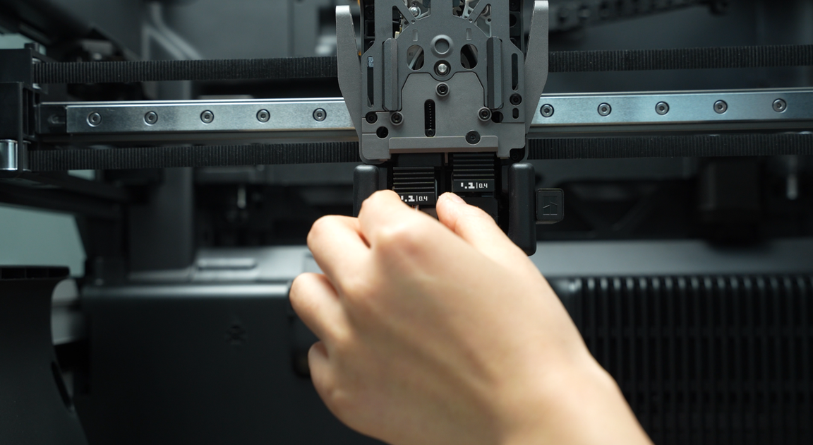
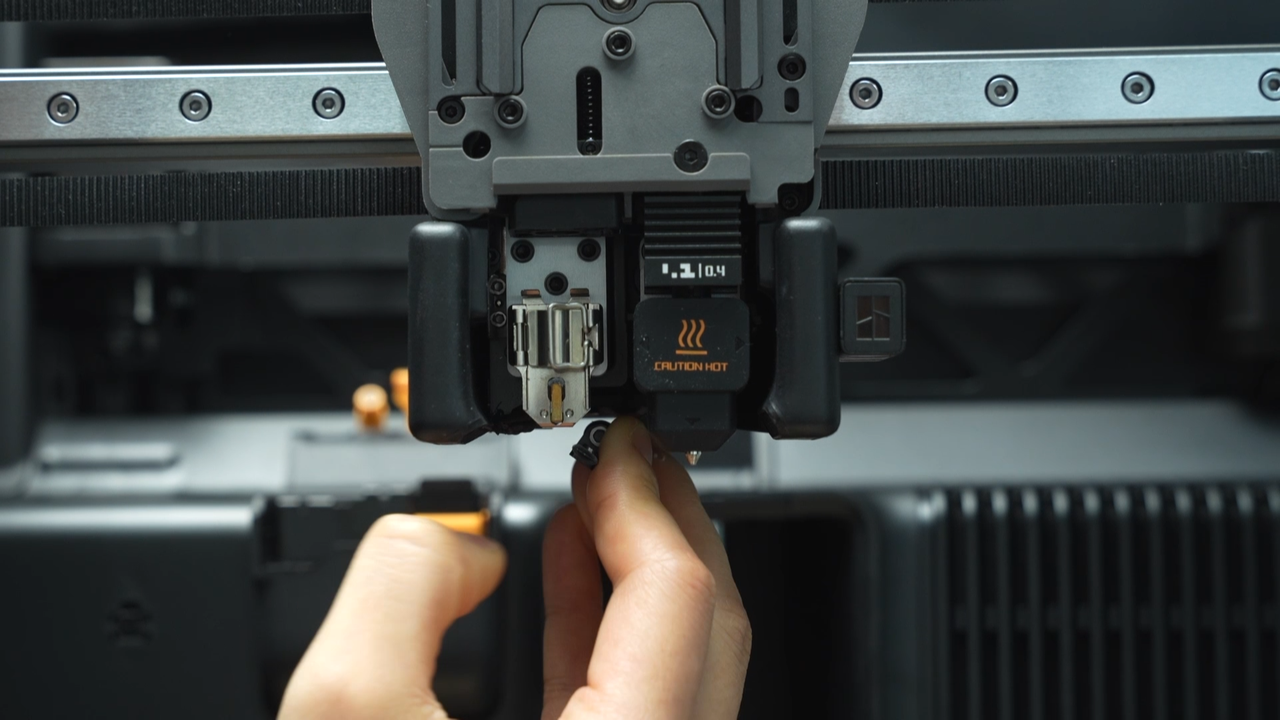
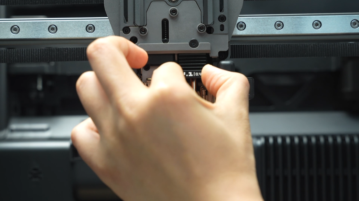
Toggle the flow blocker lever to move the flow blocker to the other side, remove the silicone sock of the remaining hotend, unlock the latch to remove the hotend, and pre-latch the latch of the heating assembly.
 |
 |
 |
 |
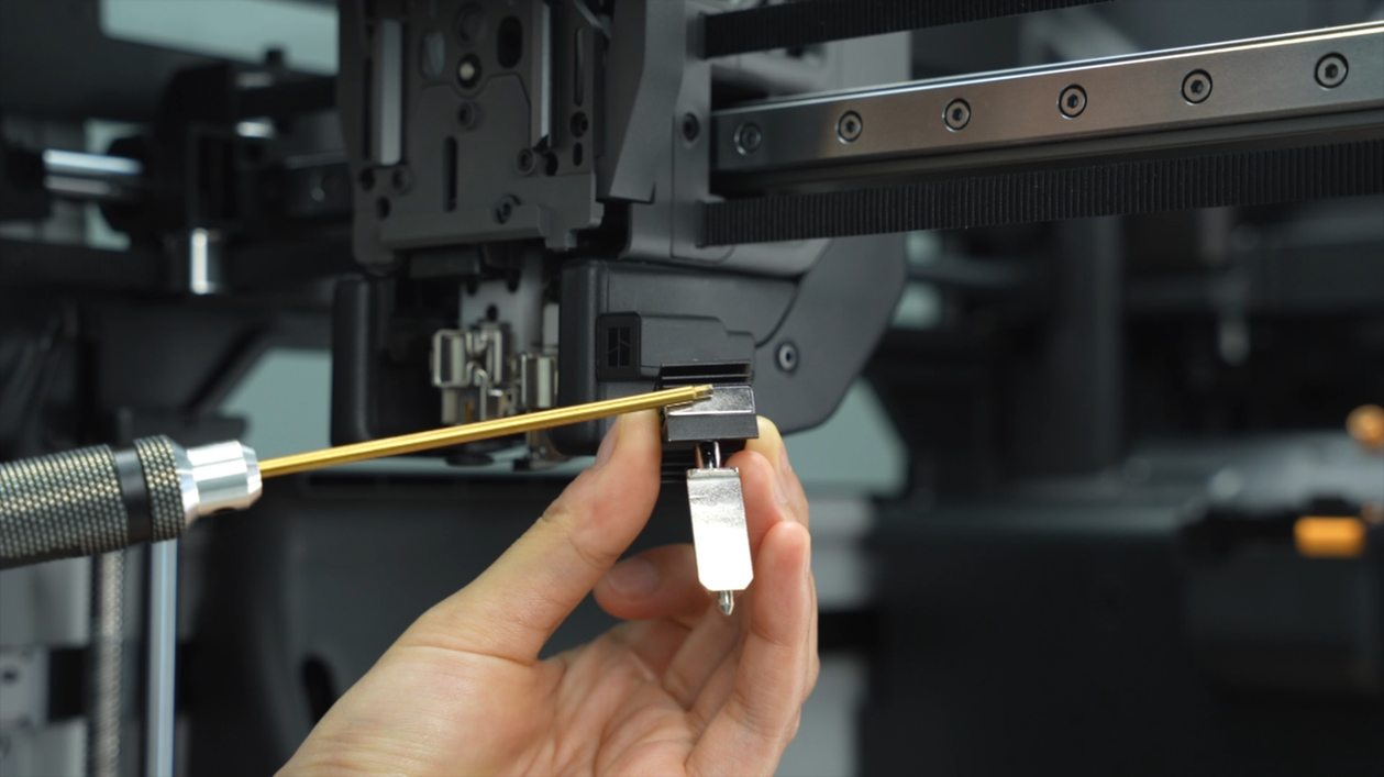
After removing the hotends, you can magnetize the allen key by attaching it to the magnet on the hotend, which will facilitate the subsequent screw removal.
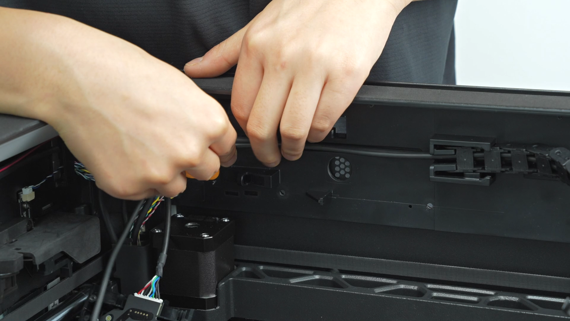
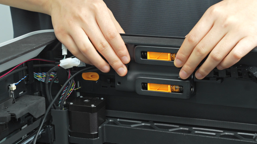
¶ Step 4:Remove the AP board cover and disconnect the USB-C cable and the MC-TH cable
Unscrew one screw from the AP board cover and remove the AP board cover.
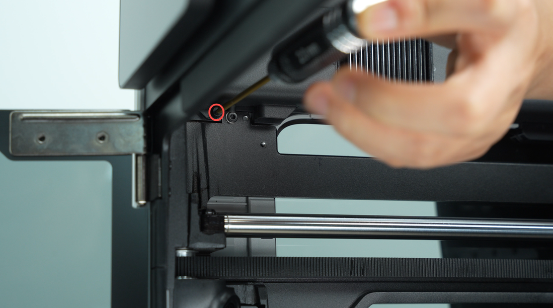 |
 |
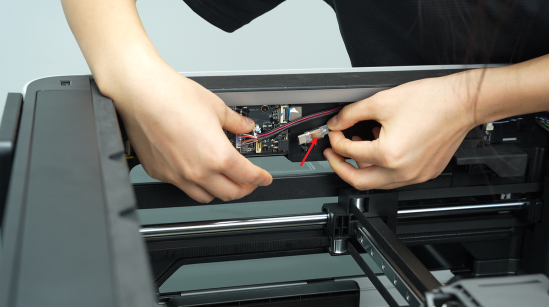
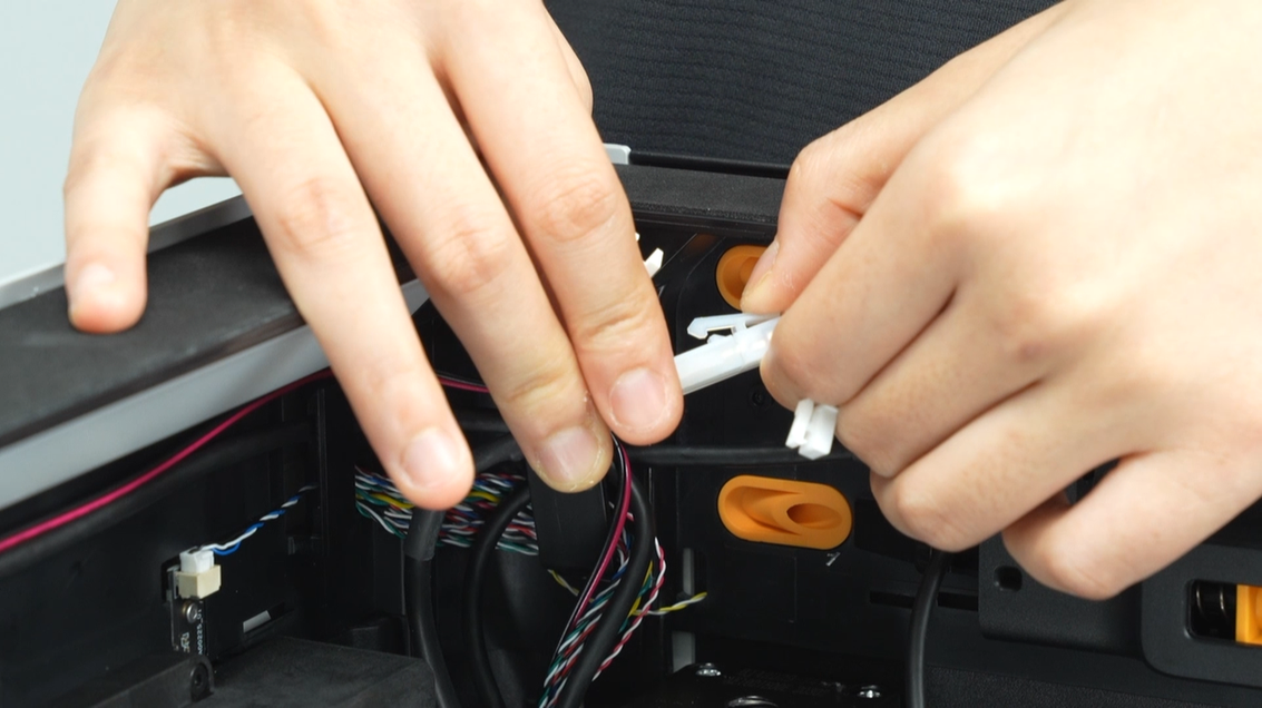
Disconnect the USB plug from the AP board and pull out the USB-C cable from the cable management slot.
 |
 |
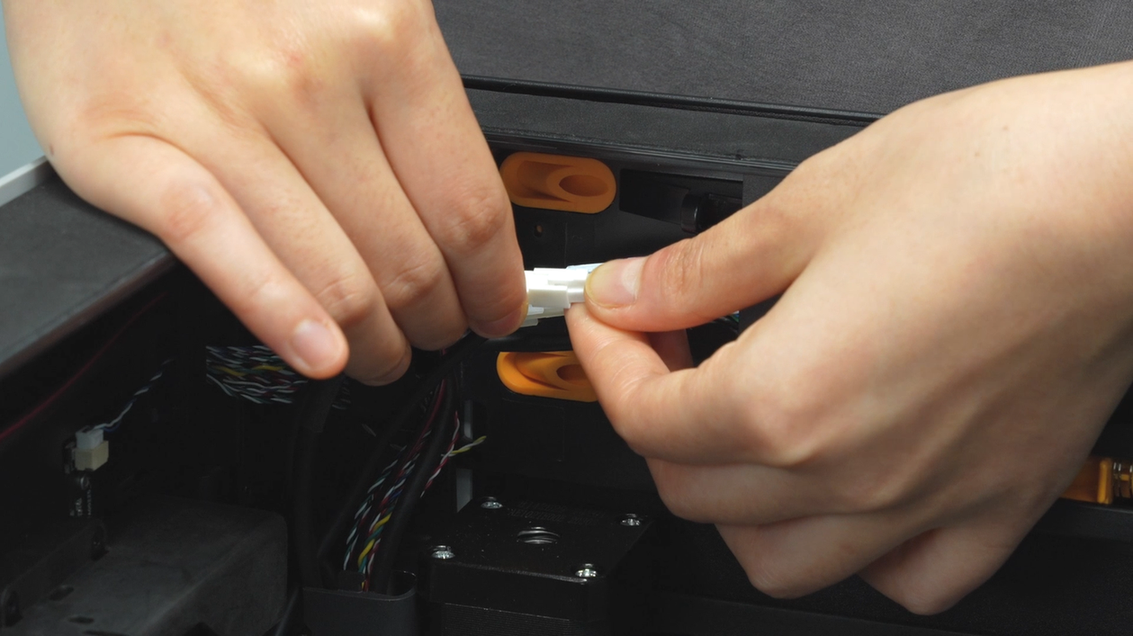
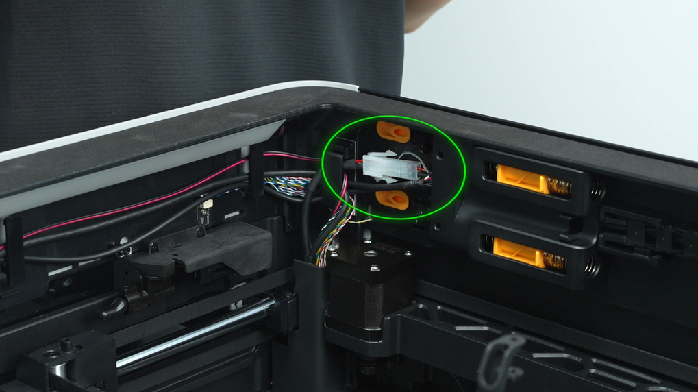
The MC-TH cable has two connectors, one is the communication connector, and the other is the power conversion connector. Press the latch to unlock and disconnect the two connectors of the MC-TH cable.
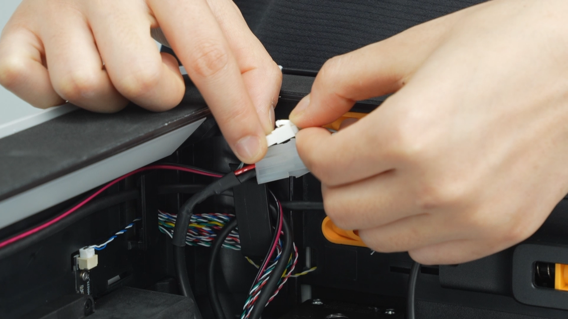 |
 |
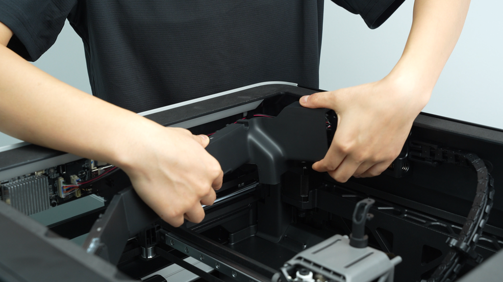
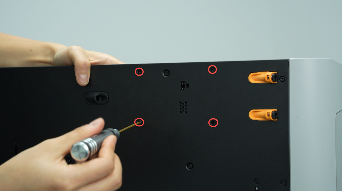
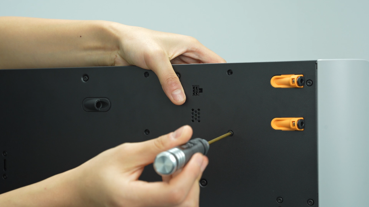
Unscrew the four screws of the buffer, loosen the buffer, revealing the USB-C cable and MC-TH cable inside.
 |
 |
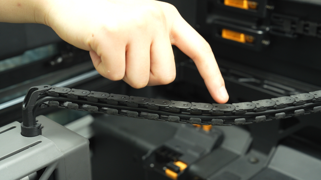
¶ Step 5:Remove the cable chain
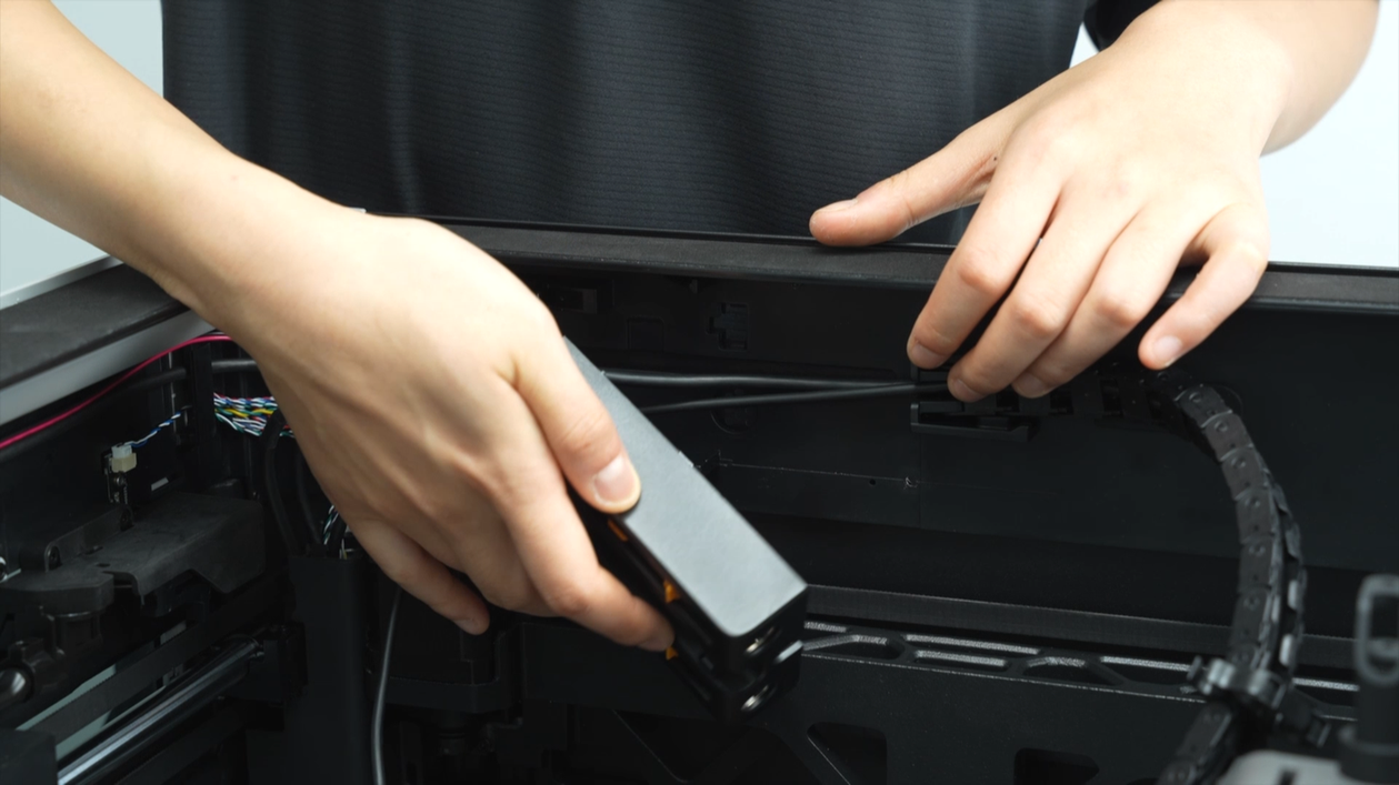
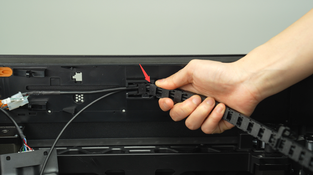
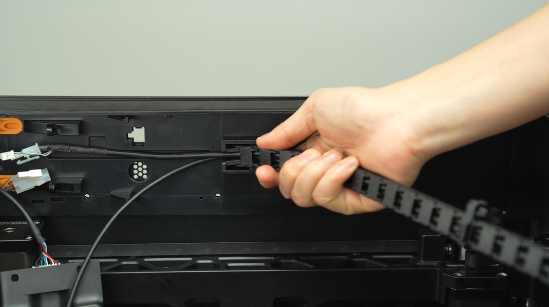
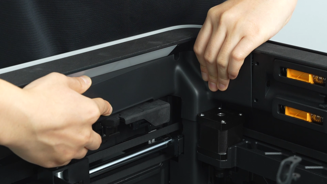
Remove this cable chain from the slot. Please note that pull the cable chain slightly downward first, allowing the upper right corner of the cable chain to disengage from the slot. And then firmly pulling out the entire cable chain.
 |
 |
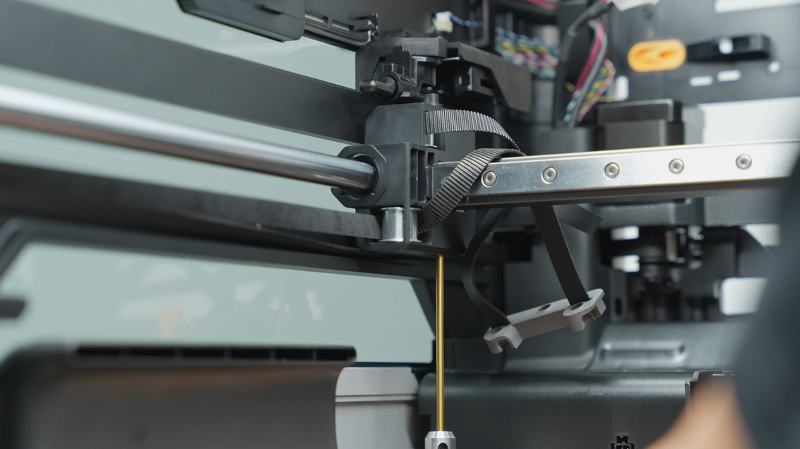
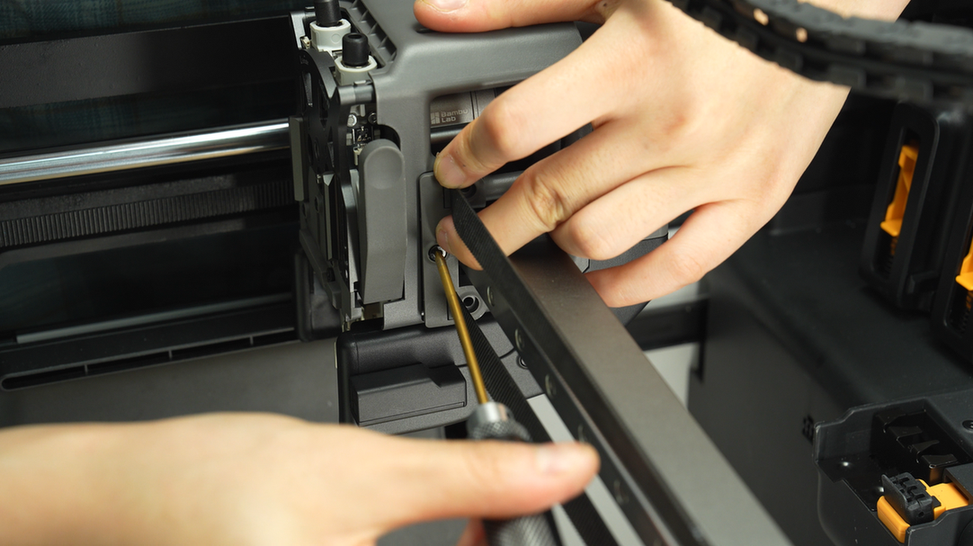
¶ Step 6:Remove the belt bracket
Unscrew the three screws on the belt bracket and remove the belt bracket.
 |
 |
 |
Use the same method to remove the belt bracket on the other side.
 |
 |
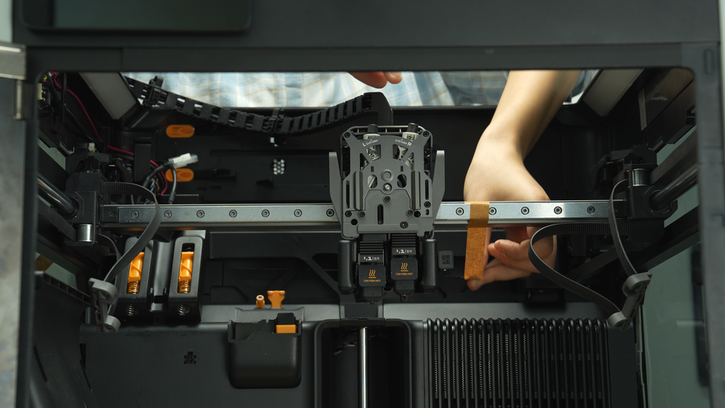
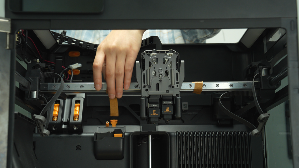
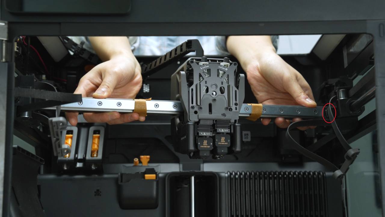
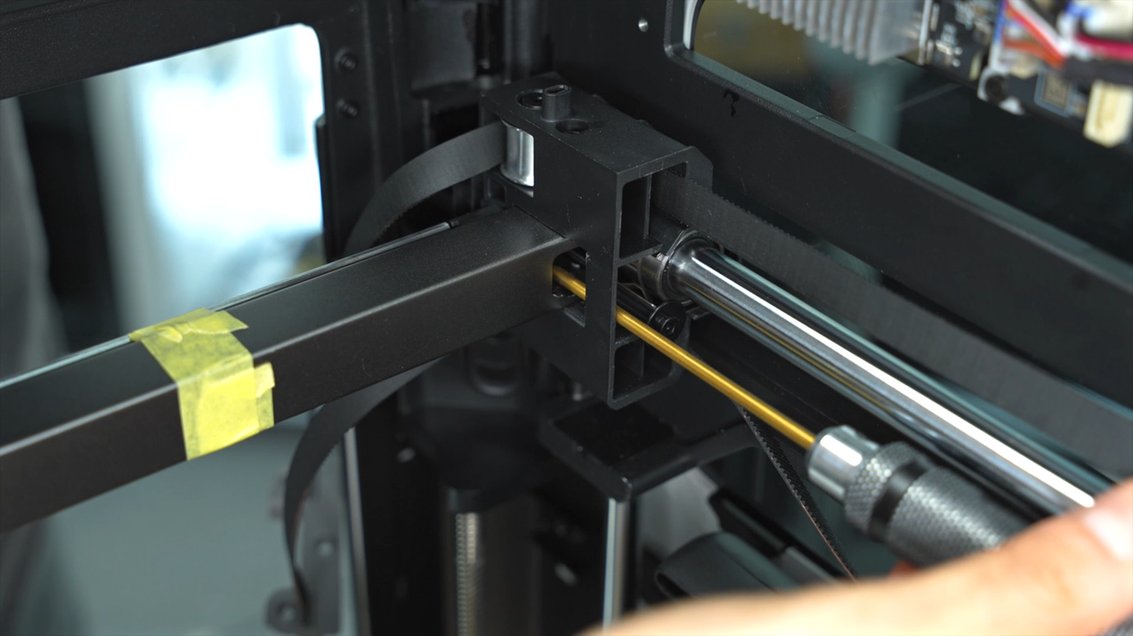
¶ Step 7:Apply traceless tape
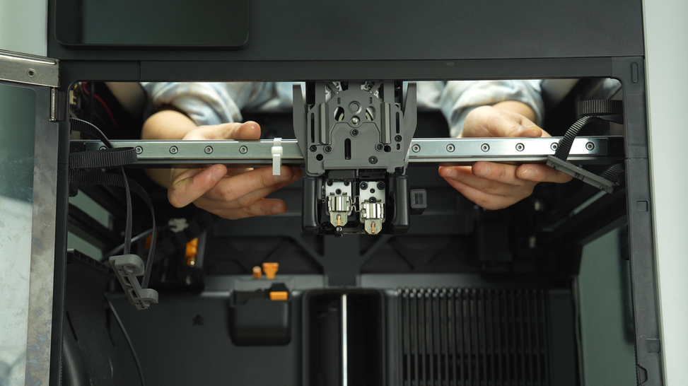
Apply traceless tape on both sides of the tool head. If traceless tape is not available, you can place some paper strips on the X-Axis assembly and then stick them with transparent tape. The purpose of this step is to restrict the movement of the tool head and prevent it from sliding out directly when removing the X-Axis assembly.
 |
 |
¶ Step 8:Remove the X-Axis assembly
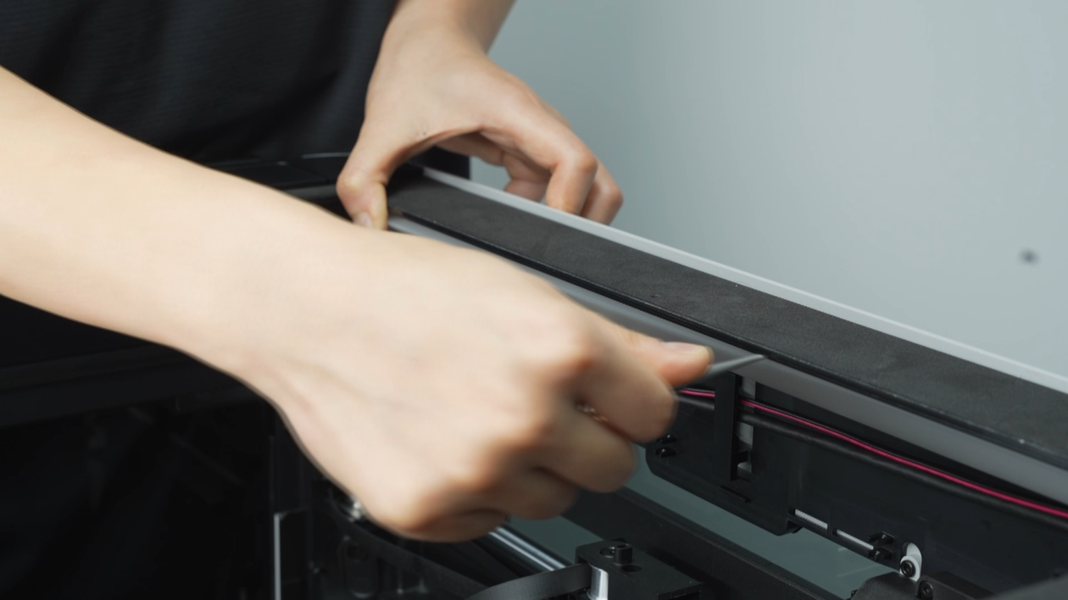
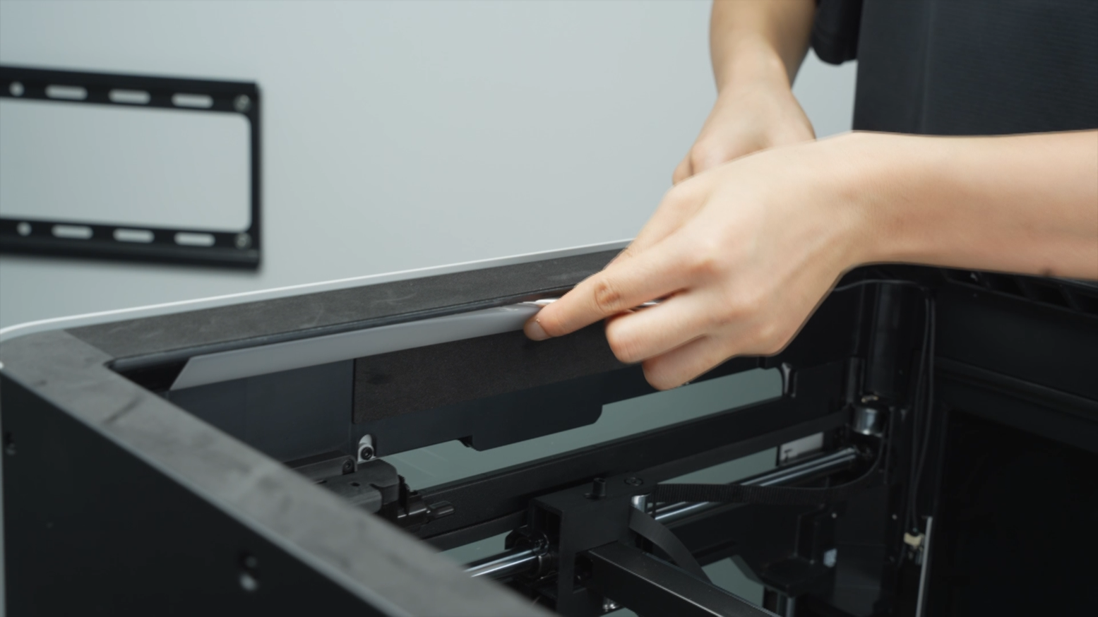
Use a tweezer to assist in removing the LED light covers on both sides.
 |
 |
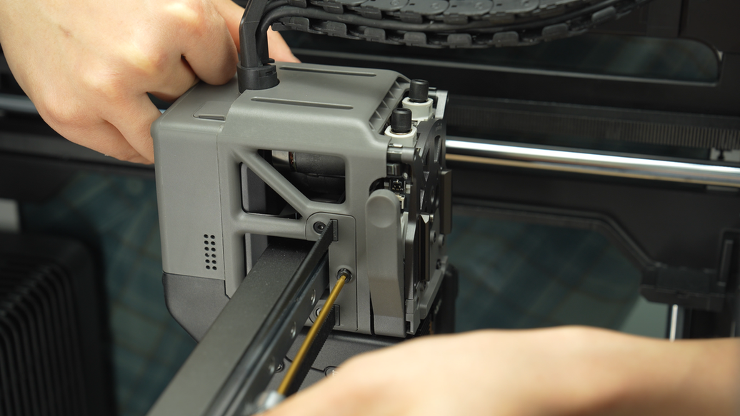
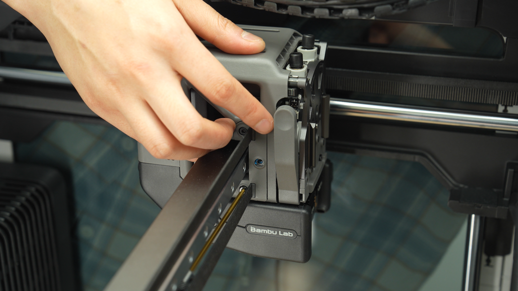
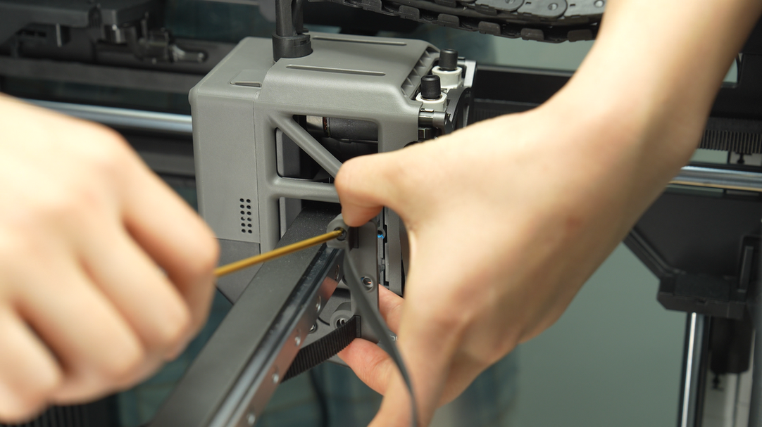
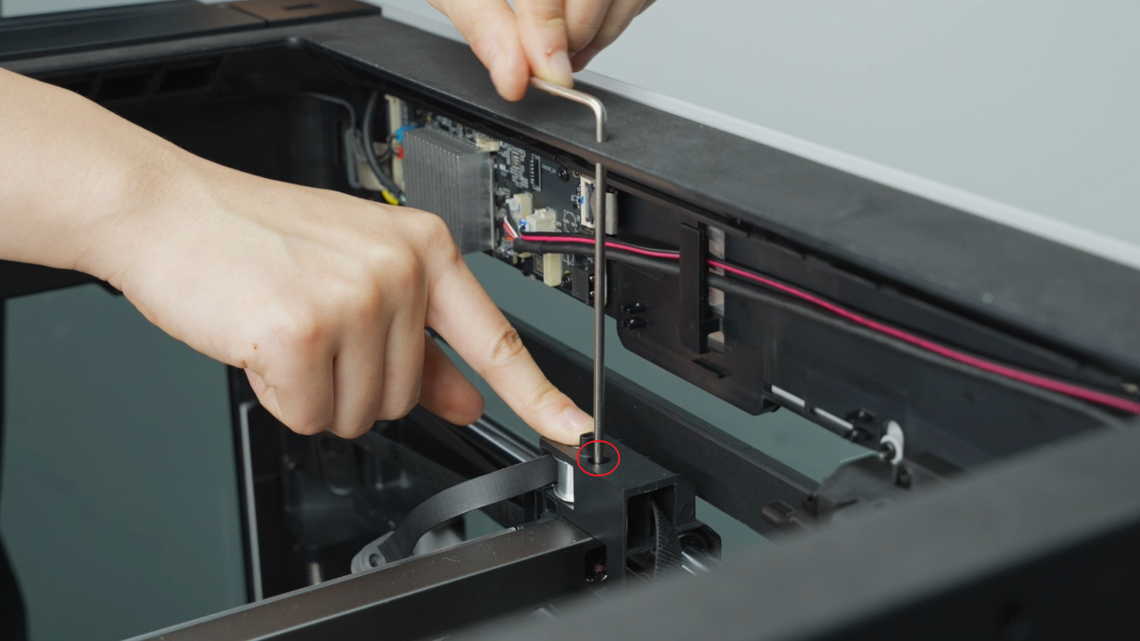
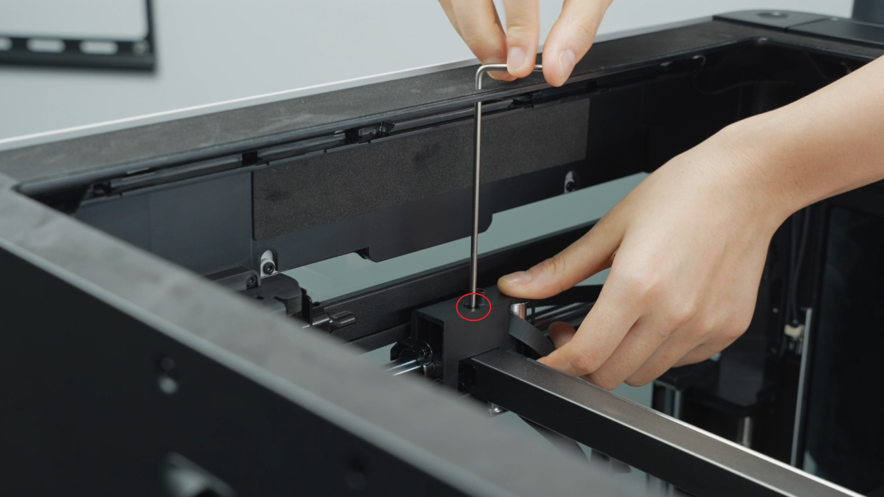
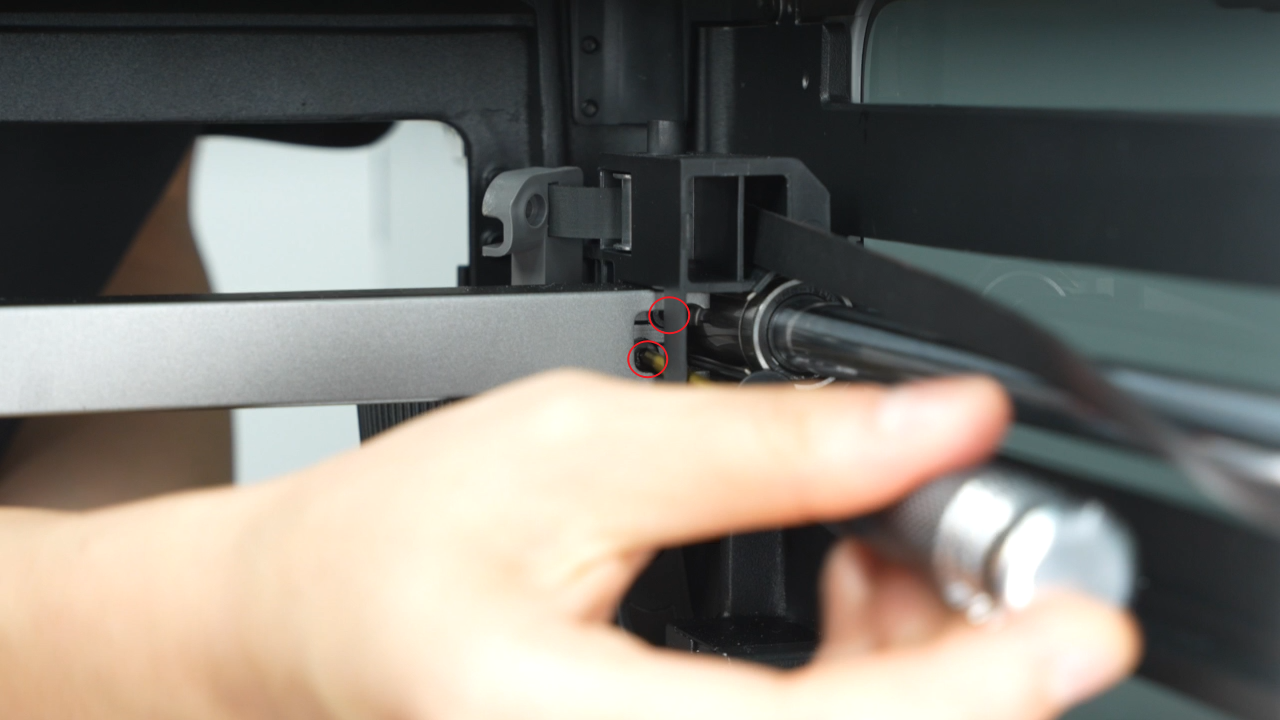
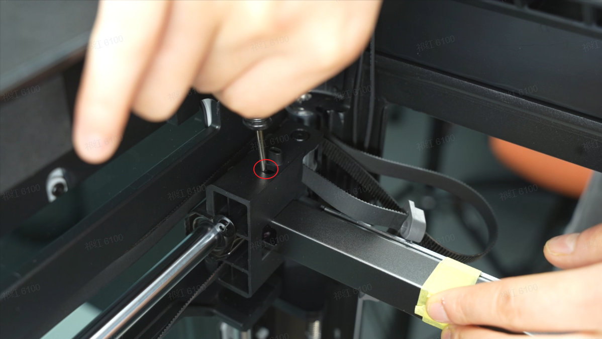
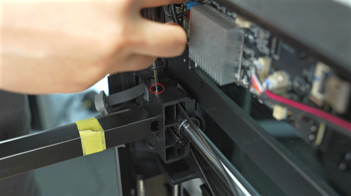
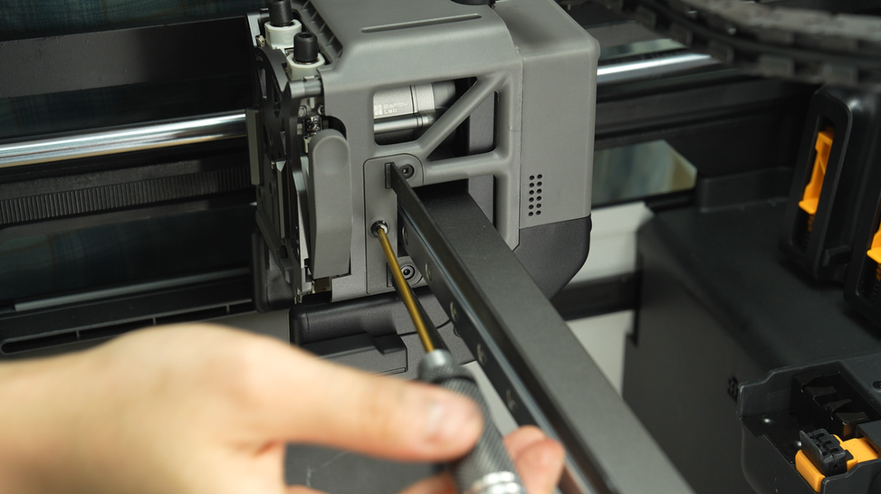
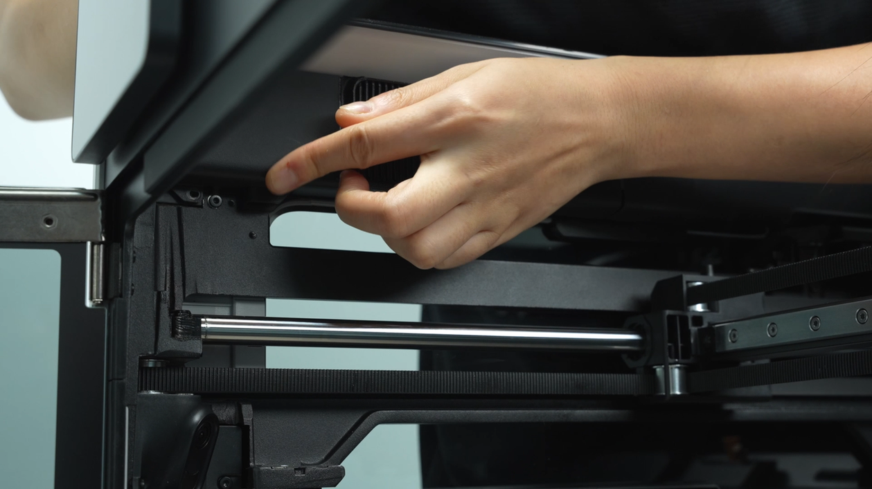
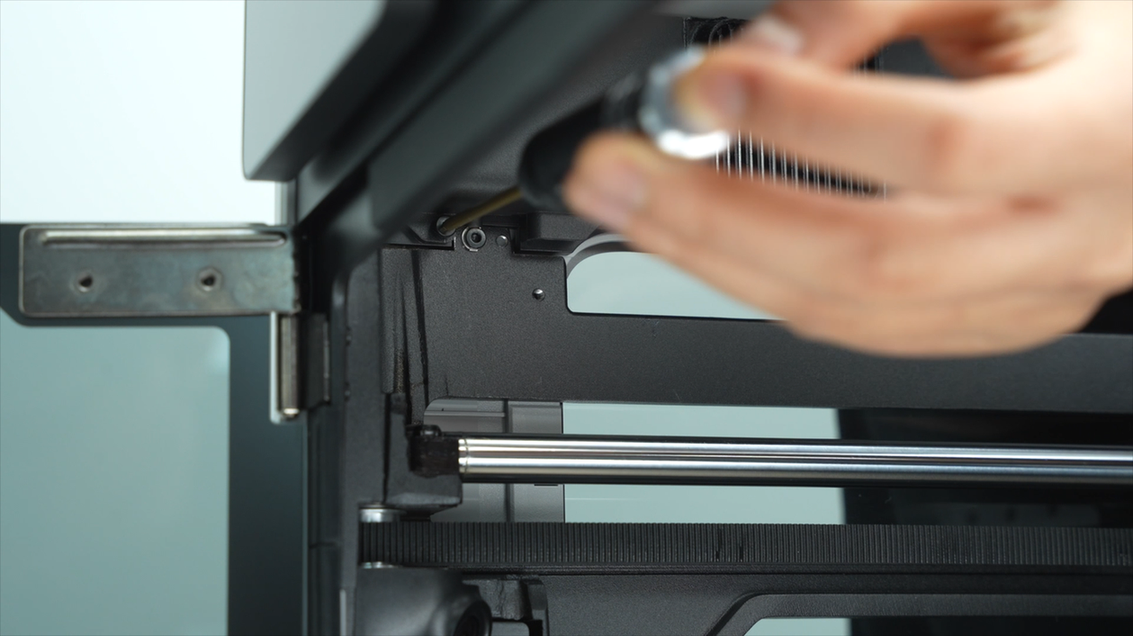
In the middle of the frame, there is a reserved hole. By using an L-shaped allen key through this hole, it becomes convenient to remove a screw on the carriage's top. In the same way, remove another screw on the top of the other side of the carriage.
 |
 |
 |
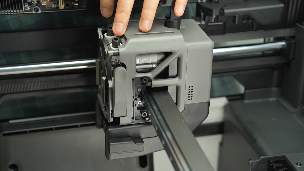
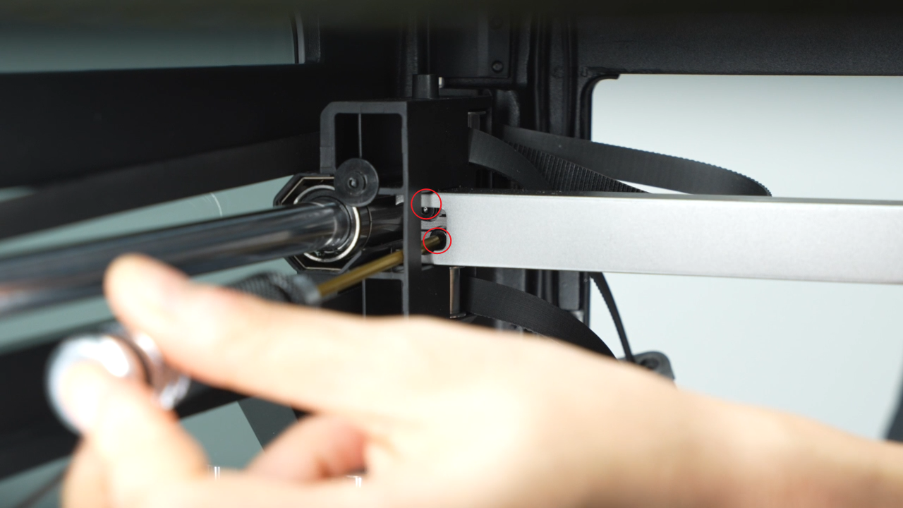
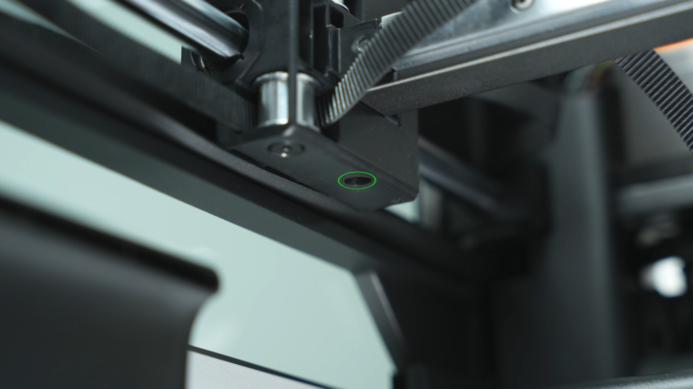
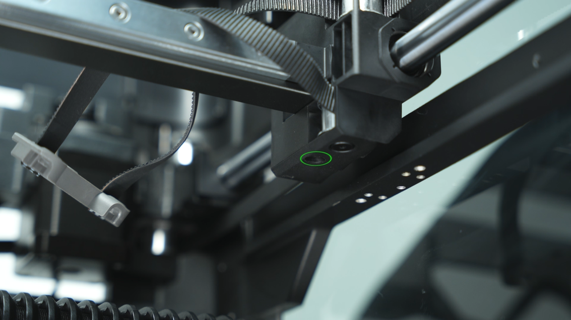
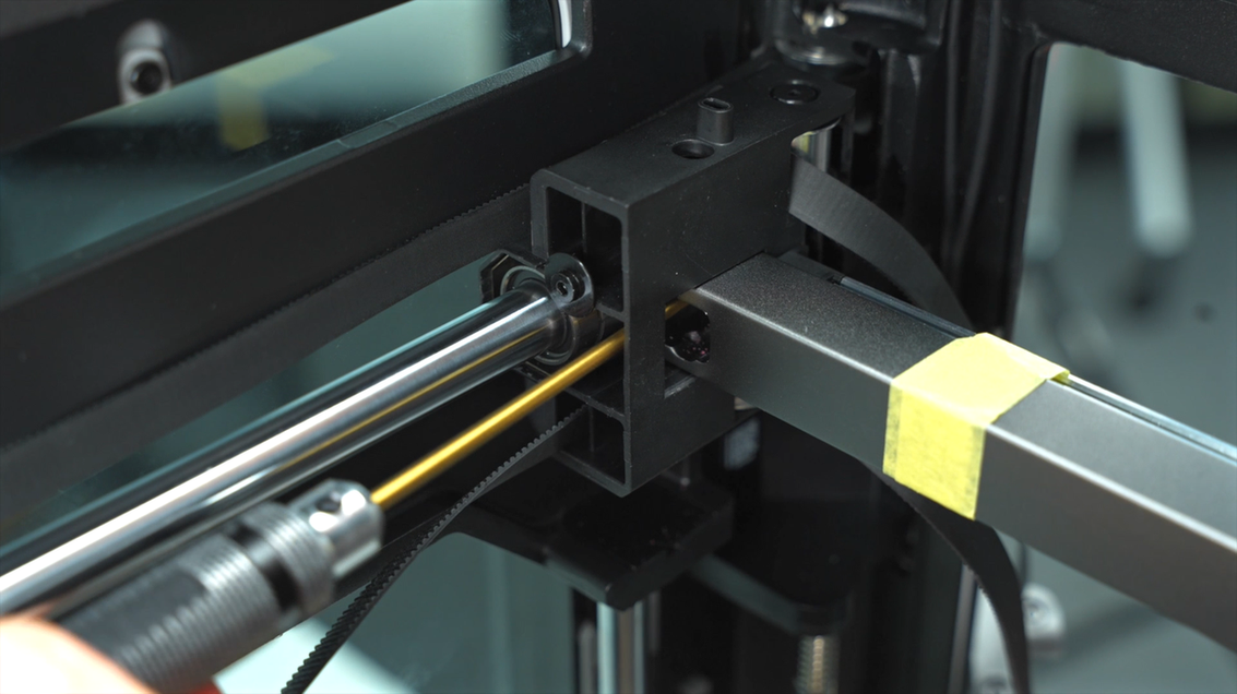
Then, remove the four screws on the side of the linear guide and the two screws on the bottom of the carriage.
 |
 |
 |
 |
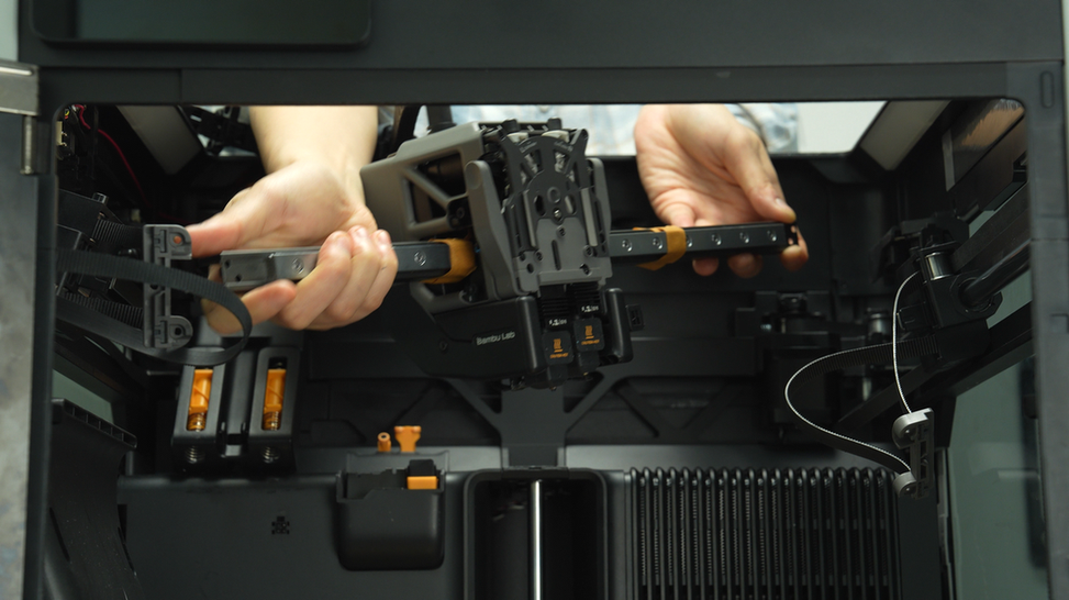
After removing all the screws, you can remove the X-Axis assembly. When removing the X-Axis assembly, first detach the right side of the linear guide from the carriage, then detach the left side of the linear guide from the carriage, and tilt to remove the X-Axis assembly.
 |
 |
¶ Assembly Guide
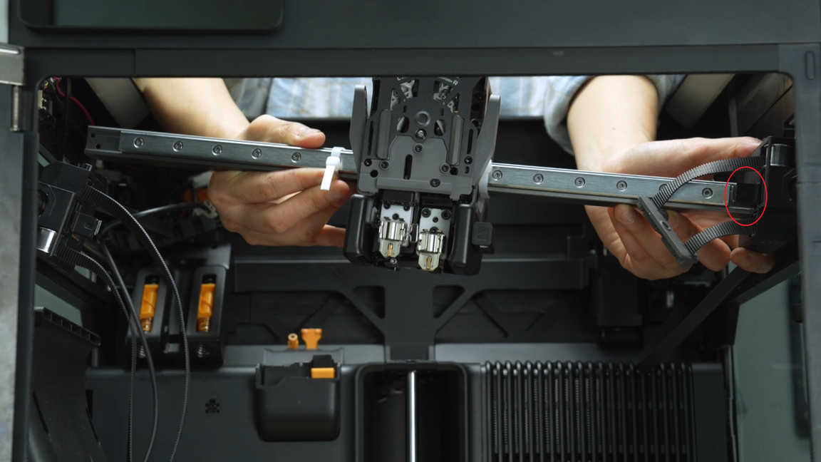
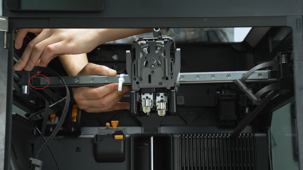
¶ Step 1:Install the X-Axis assembly
When installing the new X-Axis assembly, start by inserting the right side of the linear guide into the carriage, followed by inserting the left side of the linear guide into the carriage. Then, push the linear guide forward until it can't move any further. This step aims to use the front door pillar for positioning, ensuring that the X-Axis assembly is parallel.
 |
 |
 |
To ensure that the X-Axis assembly is parallel, it is necessary to push the linear guide all the way to the front before tightening the linear guide screws. Unlike the disassembly process, the linear guide cannot be pushed to the middle position and have the linear guide screws tightened using an L-shaped allen key.
We recommend using a short allen key to directly tighten the two screws on top of the carriage, the four screws on the side of the linear guide, and the two screws at the bottom of the carriage.
It is important to note that the screws at the top and bottom of the carriage are fine-thread screws,while the screws on the side of the linear guide are coarse-thread screws. Please do not confuse them.
 |
 |
 |
 |
 |
 |
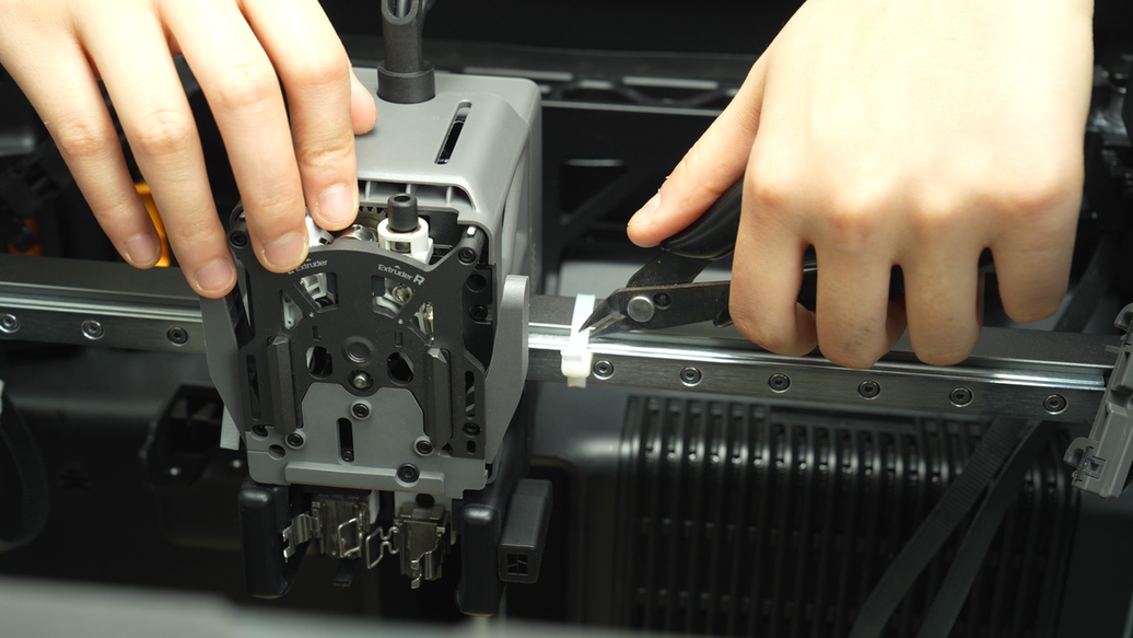
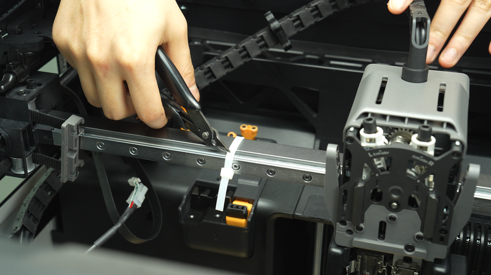
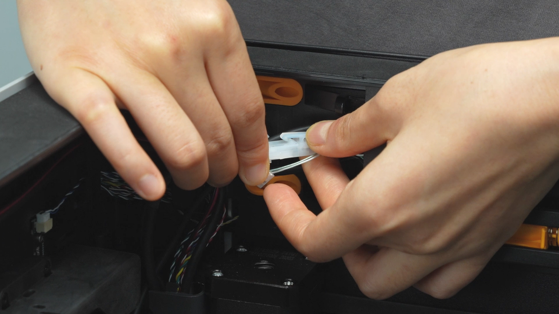
¶ Step 2:Remove the zip ties.
After the X-Axis assembly is installed, use needle-nose pliers to cut off the zip ties on both sides of the tool head.
 |
 |
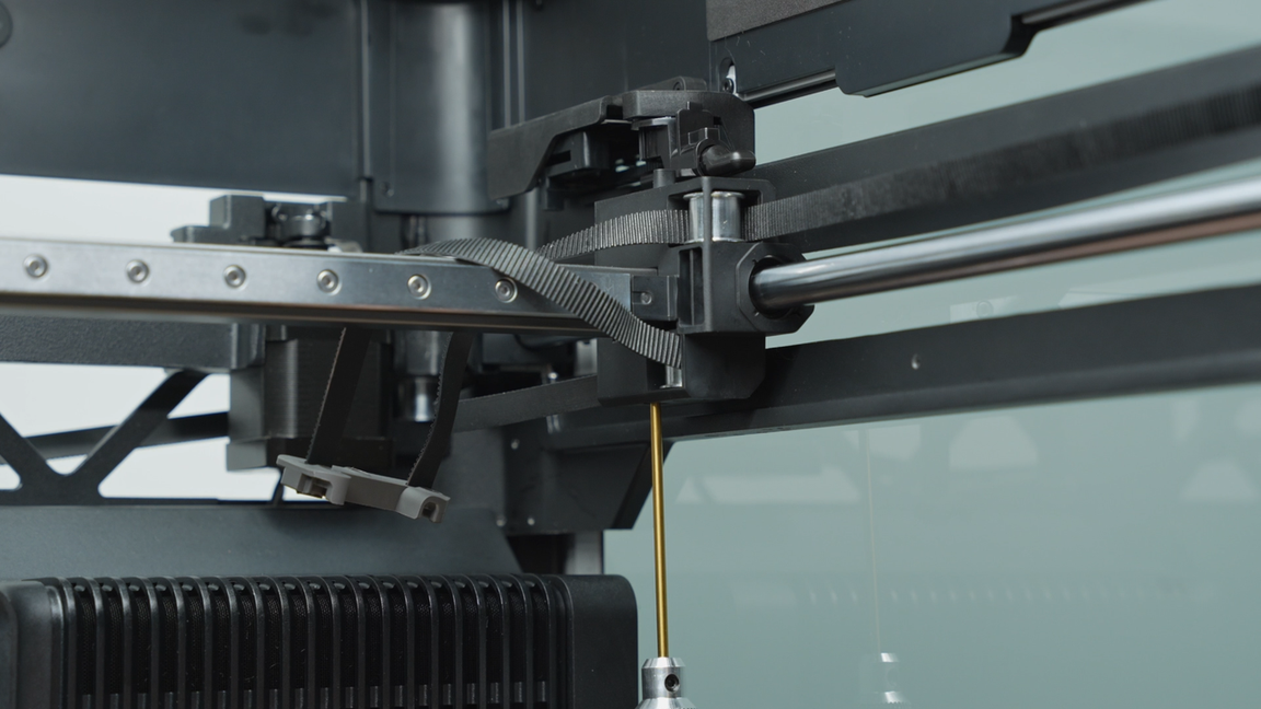
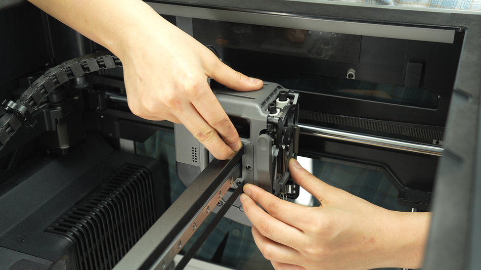
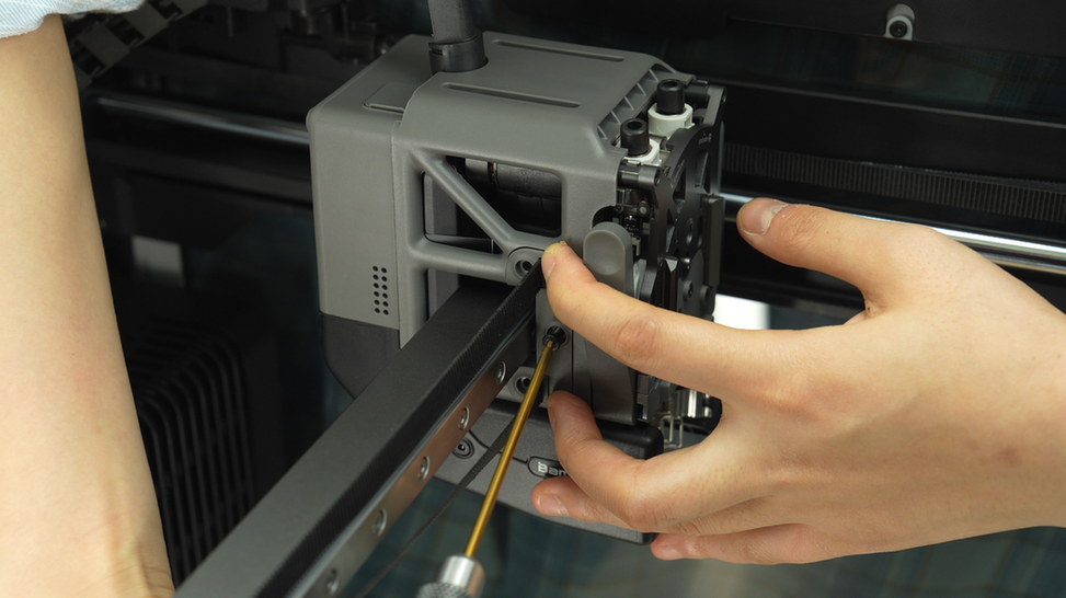
¶ Step 3:Install the belt bracket
Reinsert the belt bracket into the slot on the tool head, then tighten the three screws.
 |
 |
Next, push the tool head to the other side and install another belt bracket. Due to the stress caused by the already installed first belt bracket, it may be difficult to fit the second belt bracket. Partially tighten the middle screw first without fully tightening it. Once the top and bottom screws are fully tightened, proceed to tighten the middle screw again.
 |
 |
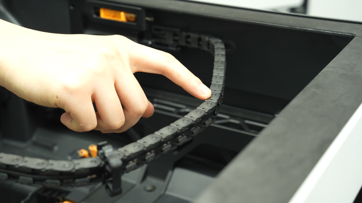
¶ Step 4:Install the cable chain
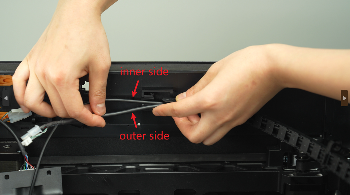
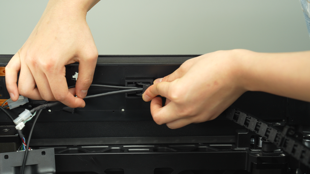
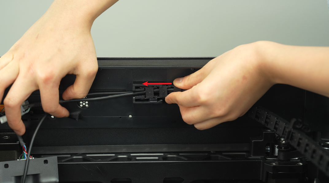
When installing the cable chain, please ensure that the thinner USB-C cable is positioned on the inner side, while the thicker MC-TH cable is on the outer side. Subsequently, insert the cable chain into the slot, press firmly, and push forward to ensure a secure installation in place.
 |
 |
 |
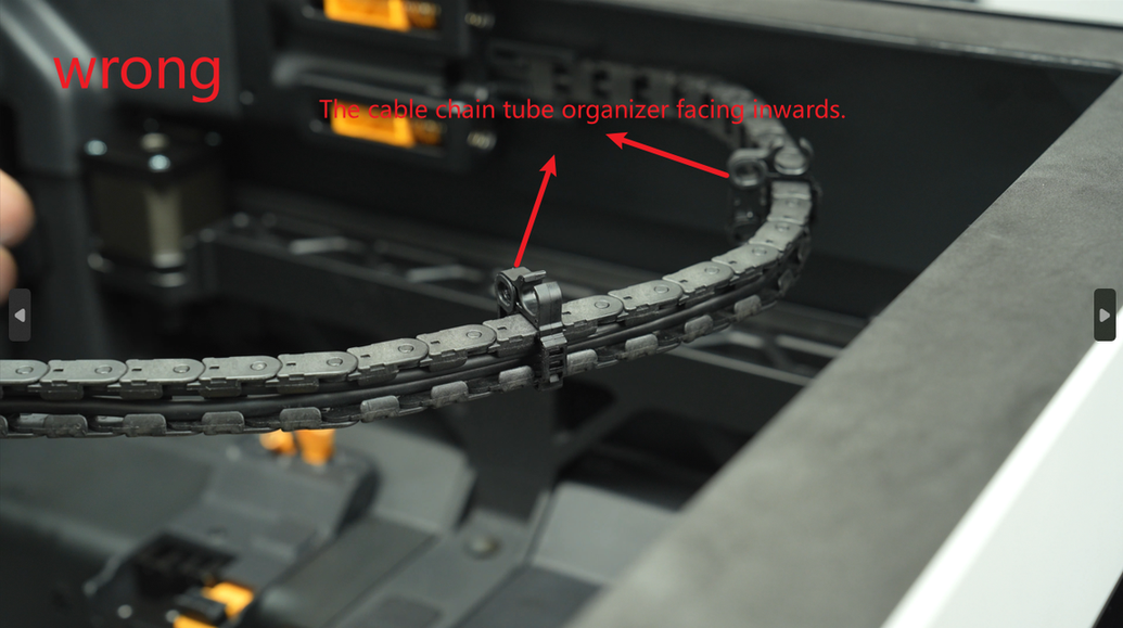
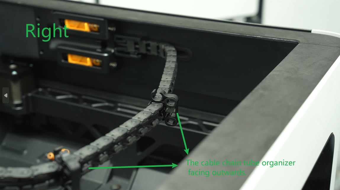
Some batches of X-Axis assembly spare parts have the cable chain tube organizers installed incorrectly. If you find that the cable chain tube organizers are facing inwards, please adjust them according to the subsequent steps.
 |
 |
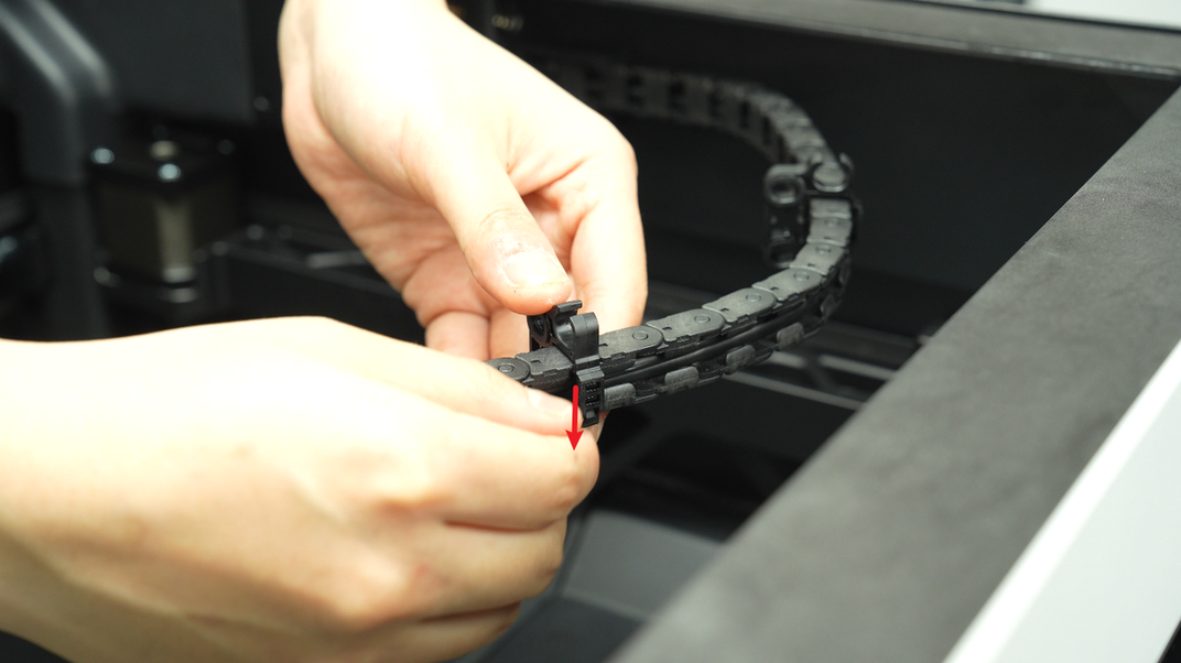
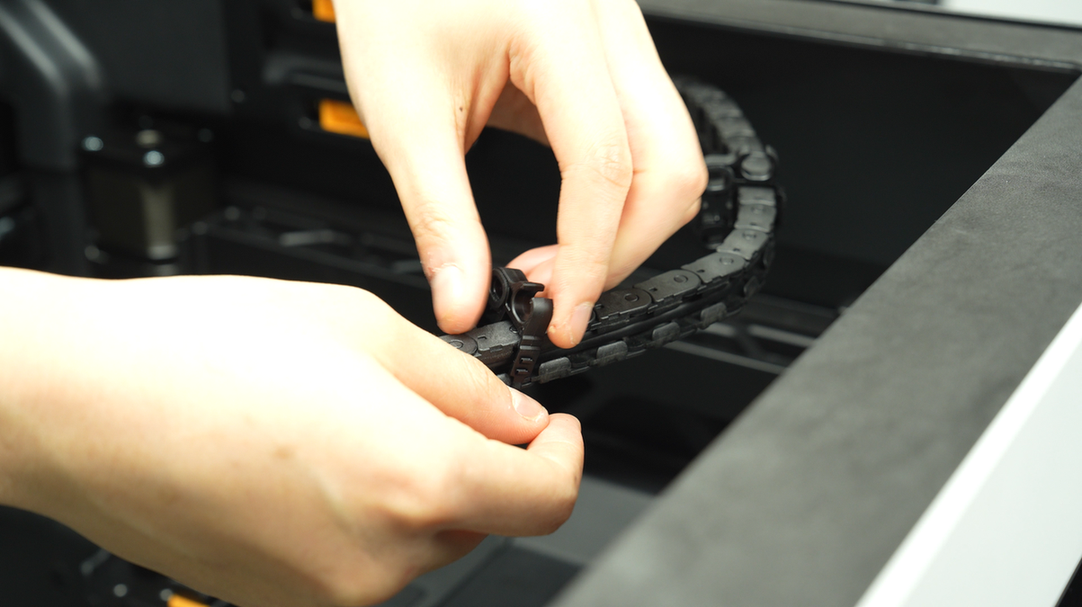
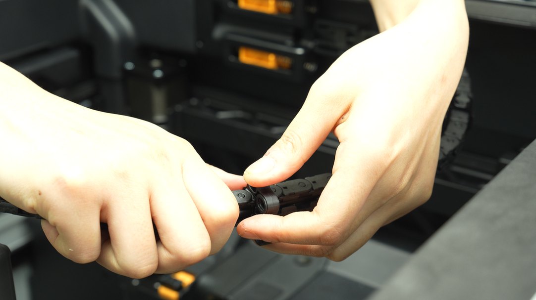
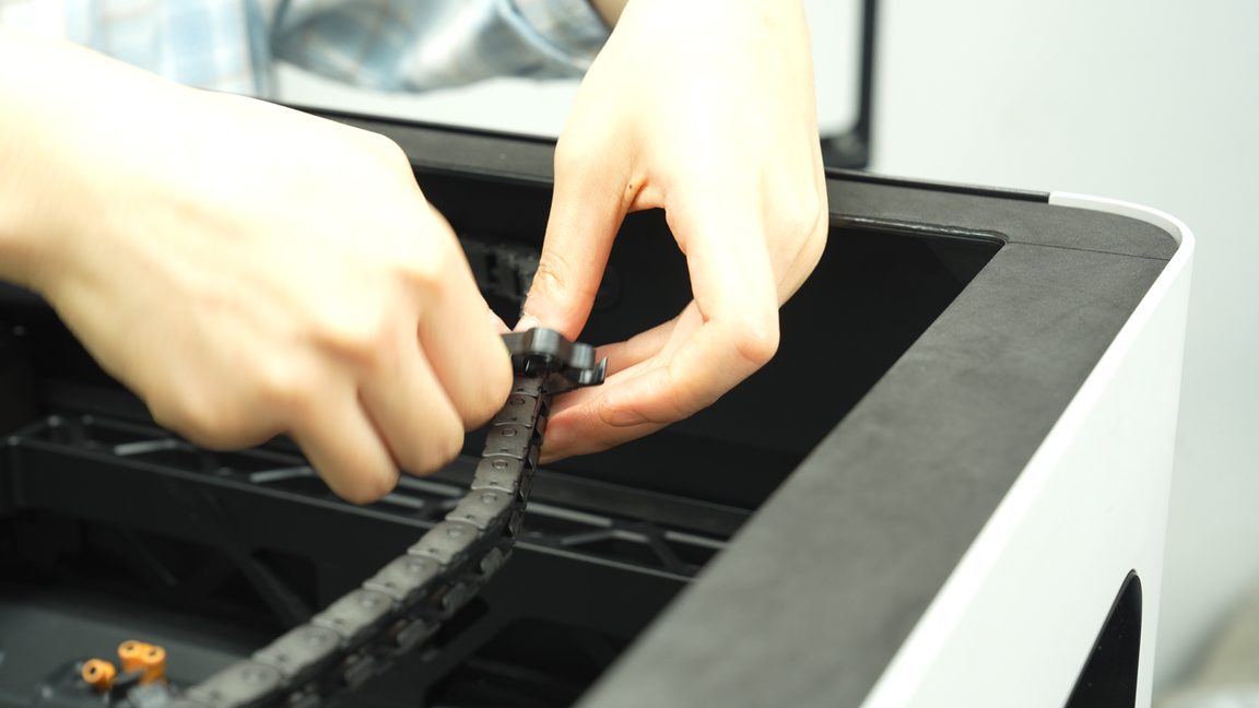
Press down to unlock the latch and remove the cable chain tube organizer. Then, reinstall the cable chain tube organizer in the correct direction.
 |
 |
The first cable chain tube organizer is installed on the 11th section of the cable chain (counting from the toolhead as the starting point), then lock the latch securely.
 |
 |
In the same way, remove and reinstall the second cable chain tube organizer. The second cable chain tube organizer is installed on the 18th section of the cable chain.
 |
 |
 |
¶ Step 5:Connect the USB-C cable and the MC-TH cable and install the AP board cover
Arrange the USB-C cable and the MC-TH cable neatly along the cable slot. Then reinstall the buffer, use one hand to hold the buffer in place to prevent it from falling and the other hand to tighten the four screws of the buffer.
 |
 |
 |
Reconnect the two connectors of the MC-TH cable and thread the MC-TH cable through the cable management slot.
 |
 |
 |
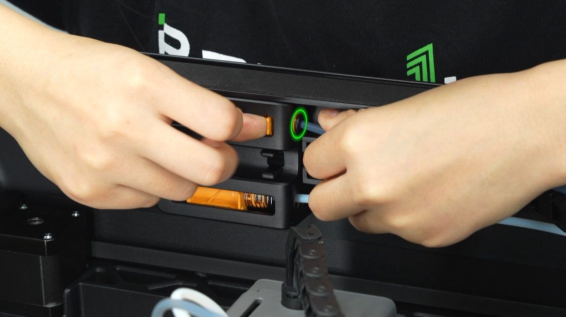
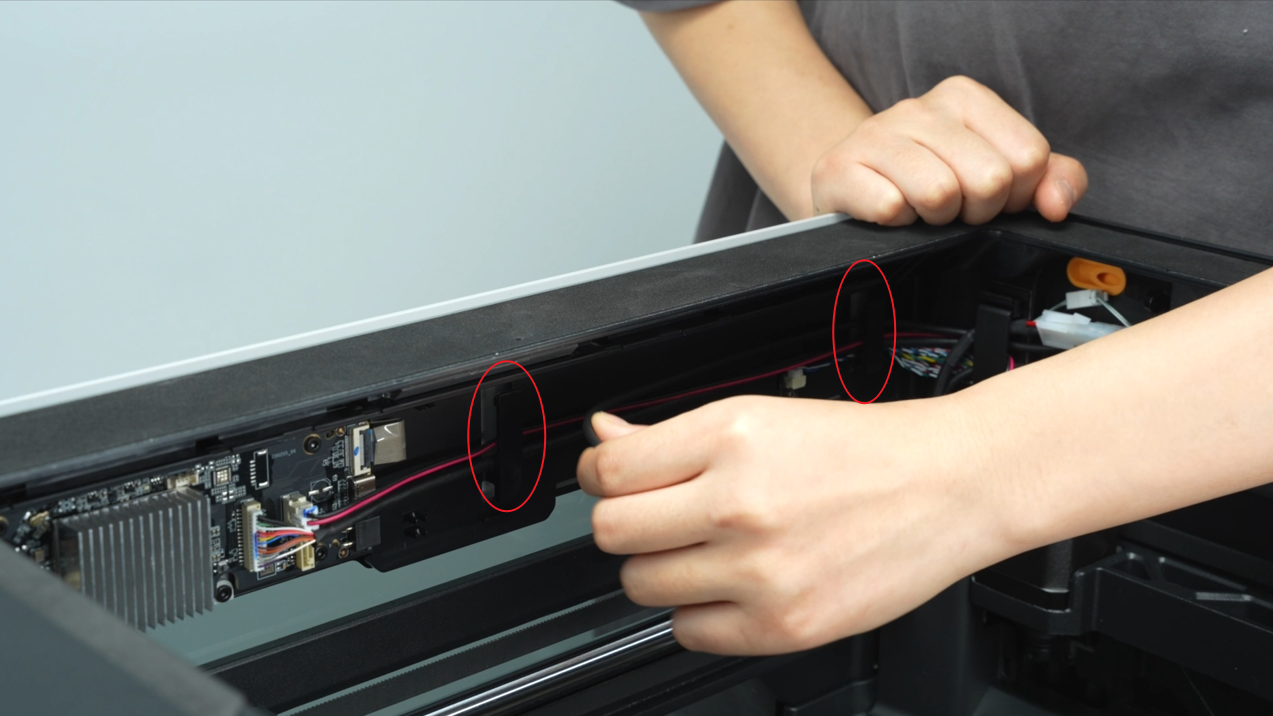
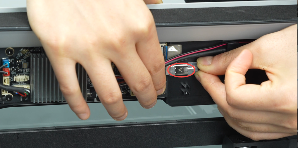
Thread the USB-C cable through the two cable management slots on the side, insert the USB plug into the AP board,ensuring that the letter 'A' is facing upward during connection, and push it forward until it cannot move any further. The connector is tight and may require some force to insert fully.
 |
 |
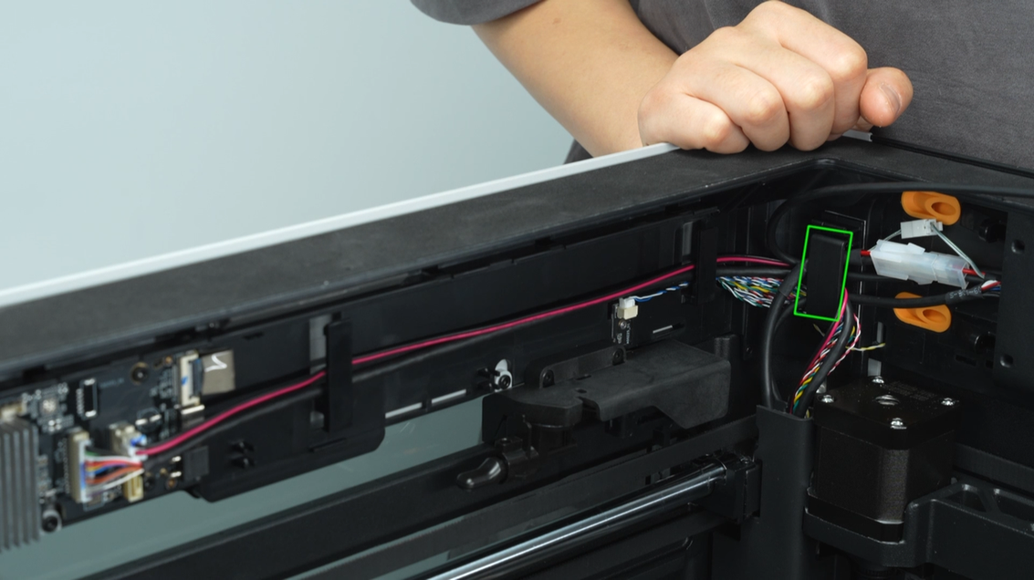
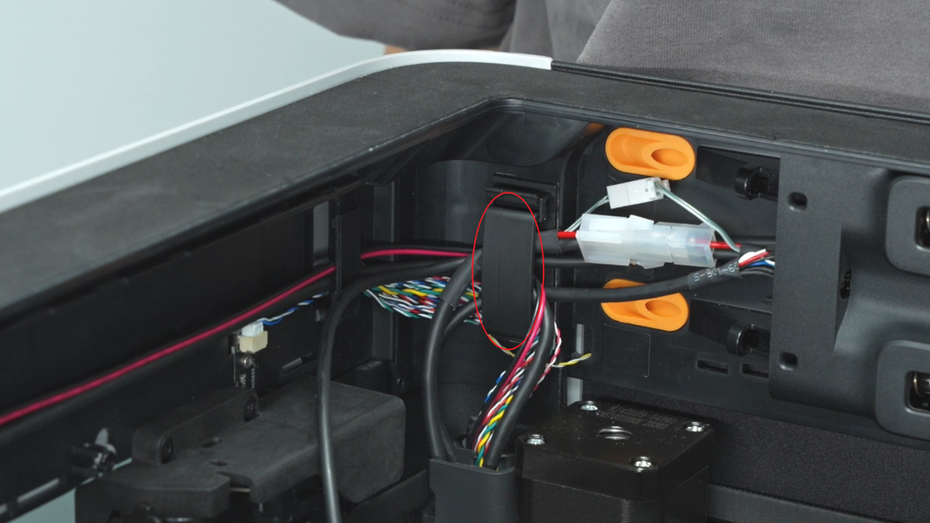
Then organize the cables, ensuring that the entrances and exits of the PTFE tubes near the buffer are not blocked by the two connectors of the MC-TH cable. It is recommended to hide the smaller connector behind the larger one.
Install the AP board cover by first fitting in the rear part, then fitting in the front part. After pressing it into place, align it with the screw holes and tighten one screw.
 |
 |
 |
 |
¶ How to verify completion/success
Restart the printer and perform calibration to check for any error warnings. If the printer indicates that the belt needs tightening, adjust the belt accordingly.
¶ End Notes
We hope the detailed guide provided has been helpful and informative.
If this guide does not solve your problem, please submit a technical ticket, we will answer your questions and provide assistance.
If you have any suggestions or feedback on this Wiki, please leave a message in the comment area. Thank you for your support and attention!