¶ Why is it necessary to calibrate the laser focus?
Since the laser module is manually installed on the toolhead, the height difference between the laser itself and the nozzle will be affected by the processing tolerance and assembly tolerance, which will cause the relative height between the laser focus and the nozzle to differ slightly from the design value. If the processing is still carried out according to the design value, it is possible that the laser focus will not be at the expected height during cutting or engraving, resulting in poor processing results.
¶ When should the laser focus be calibrated?
-
After the laser module is installed for the first time;
-
The laser module is bumped (including the laser height probe on its side);
-
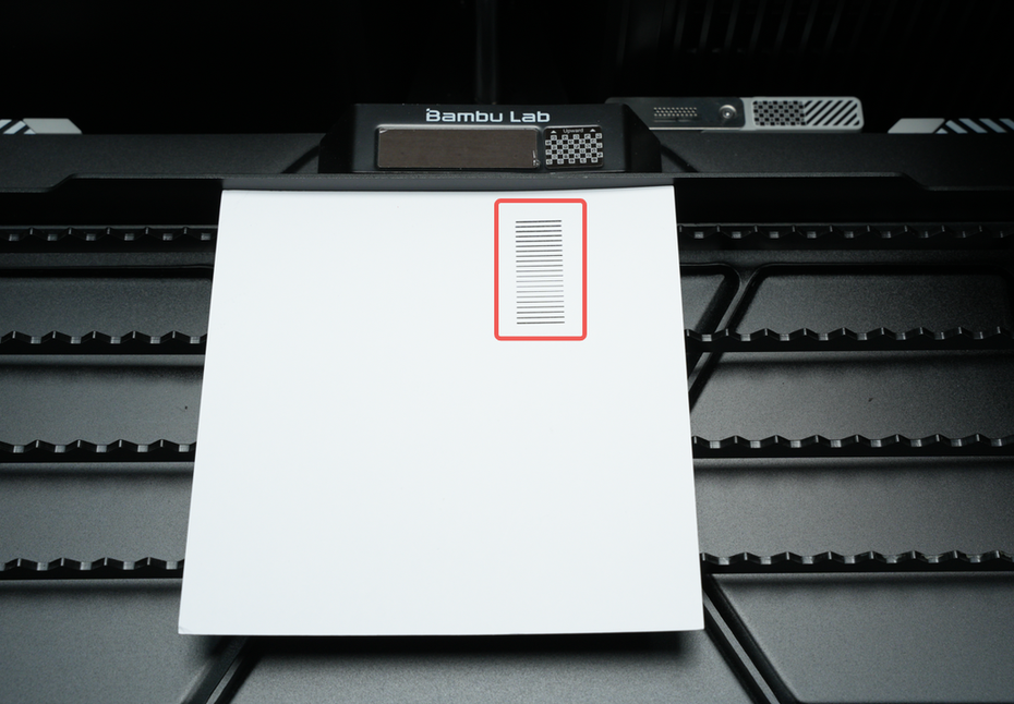
The line width appears to be thicker during engraving.
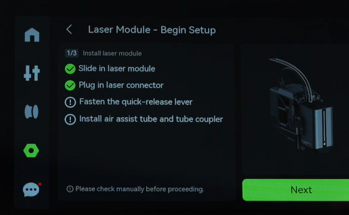
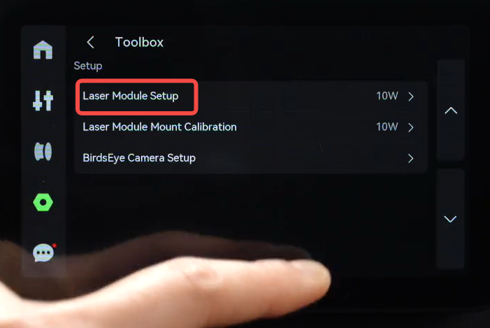
¶ How to trigger laser focus calibration?
Currently, when the engraving laser is installed on the toolhead and the power wire is plugged in, the laser focus can be calibrated in the laser module setup.
The operation steps on the printer screen are: Settings -> Toolbox -> Laser Module Setup.
¶ Laser focus calibration operation process
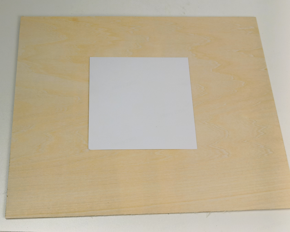
¶ 1. Prepare the calibration materials
As shown in the following picture, find white square paperboard:
What should I do if I can't find the square paperboard, or if it is bent or damaged?
-
Option 1: The paperboard has a thickness of 0.35mm. If you can find such paperboard, please cut a square of 100mm x 100mm. Note: Paperboard must be light-colored, dark-colored paperboard cannot be used.
-
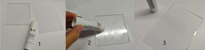
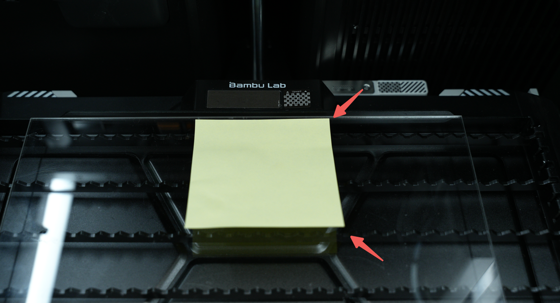
Option 2: If you have a transparent acrylic sheet, A4 paper (or sticky notes), and glue, you can use them, as shown in the image below. Note: Be sure to apply glue all over the acrylic board to prevent the paper from warping or bulging.
- Option 3: Standard A4 paper. It is recommended to cut the paper to 120mm * 120mm. Since A4 paper is relatively lightweight, the knife strips can be placed closely to support the paper. Note: The paper must not be warped.
The following are the materials we have tested that are not suitable for calibration:
-
Ordinary A4 paper ---- too soft and will deform due to heat;
-
Wood board: The surface texture and heat overflow will make the marking line unclear, so it is barely usable;
-
Laser dimming paper ---- If the power at the focus is too high, it will burn through directly;
-
Anodized aluminum plate ---- surface texture will affect the recognition effect.
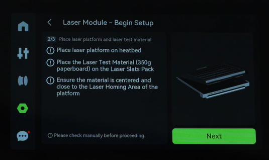
¶ 2. Calibrate the placement of materials
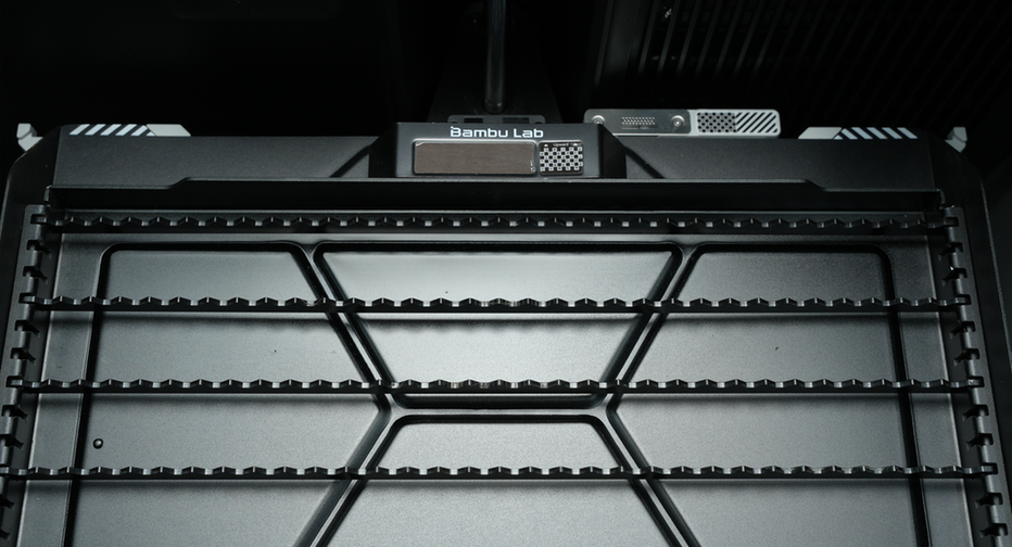
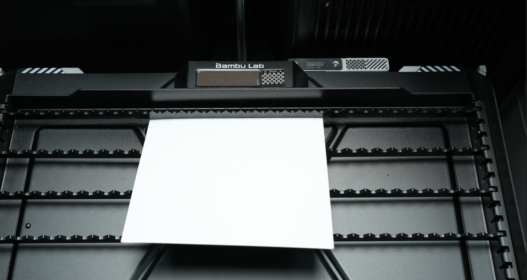
First, at least two blade strips need to be placed near the calibration table close to the laser platform, as shown in the image below:
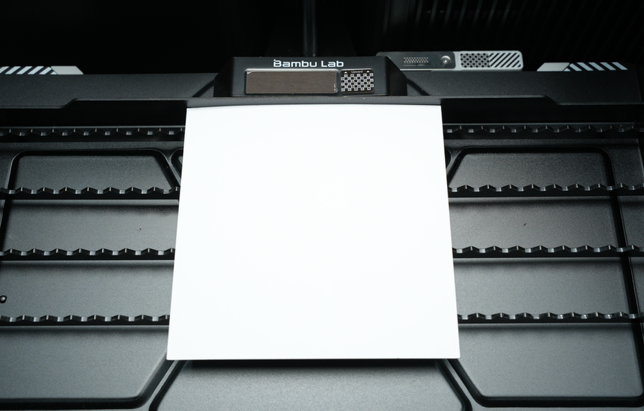
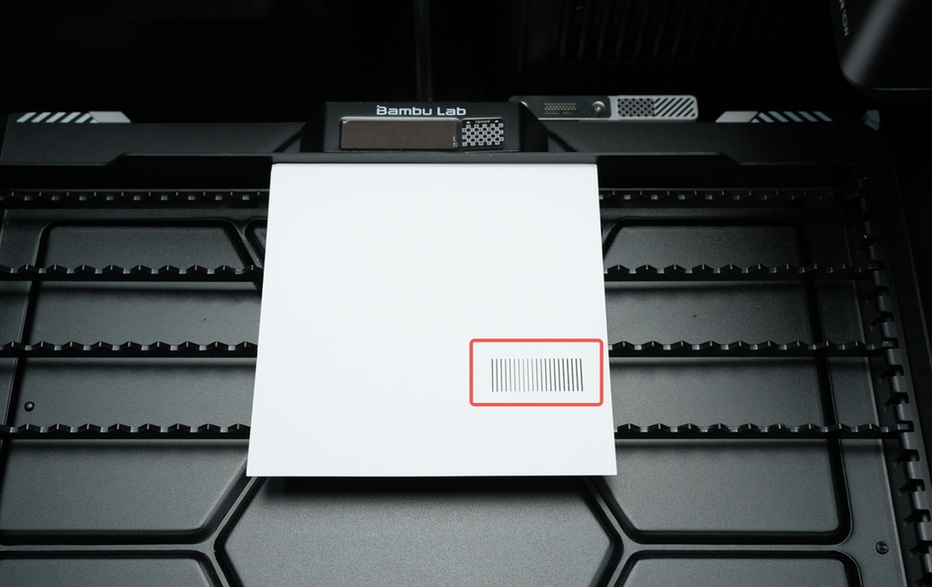
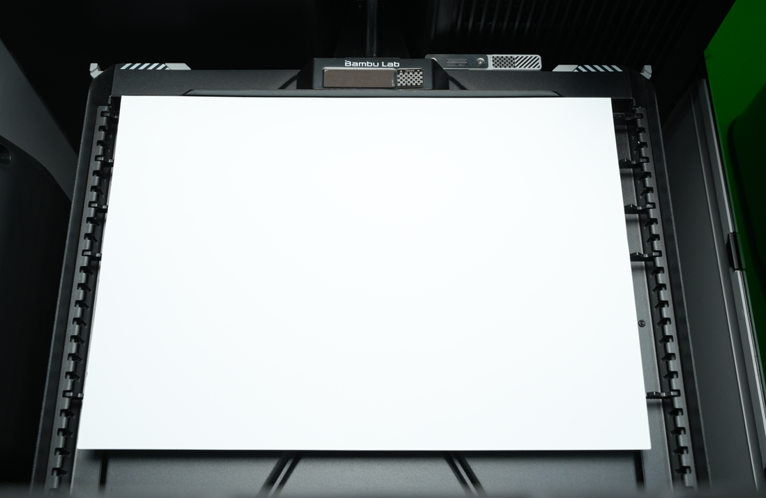
Then, place the calibration materials in the center position tightly against the calibration table. The following images show the correct examples:
- Although the paper has been used, the burned area is not within the scope of this calibration.
- Sticky note paper or A4 paper is completely glued to the transparent acrylic board.

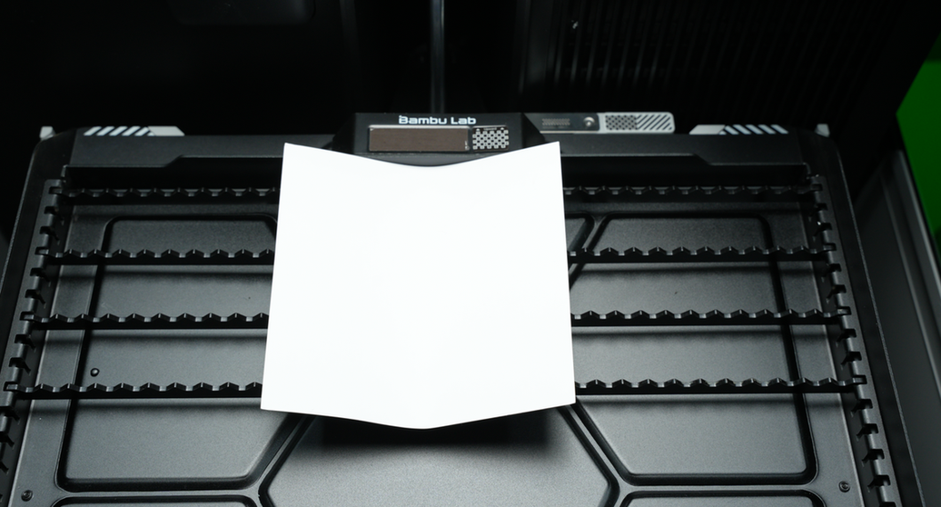
The following are examples of incorrect placement:
- The paper falls into the rack and is not close to the calibration table.
- The paperboard is warping.
- Place A4/A5 paper directly on the platform. The paper is too thin and can be easily blown away.
- The area where the paperboard is burned is exactly the area that will be used for this calibration.
- When using the acrylic board and note paper, the note paper was not completely attached to the acrylic board with glue, causing its edges to curl up.
¶ 3. Start calibration
After placing the calibration materials, follow the steps on the screen to execute the laser module setup process.