¶ Background
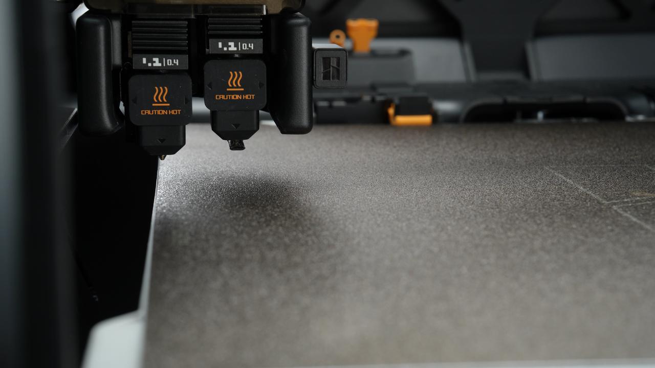
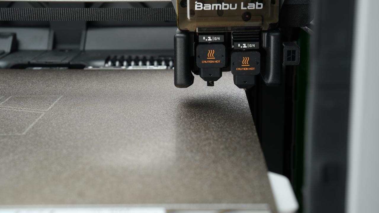
The H2D is a two-nozzle printer, and the printable range of the printer's two nozzles is different. This article will describe the limits of the printable area of the H2D printer and some considerations.
| Dual nozzle switching | Only the left nozzle can reach the leftmost side of the heatbed | Only the right nozzle can reach the rightmost side of the heatbed |
|---|---|---|
 |
 |
 |
¶ Printable area limit
¶ Horizontal printable area
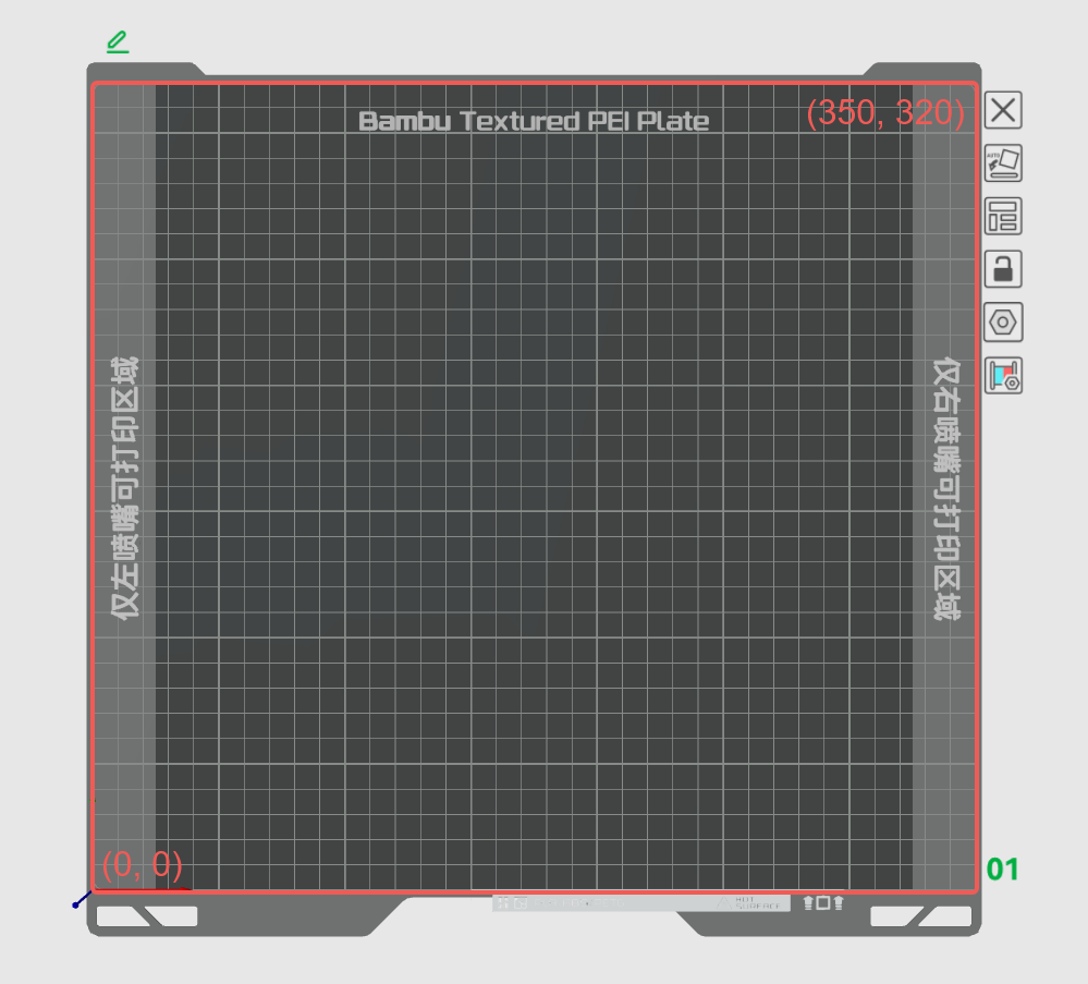
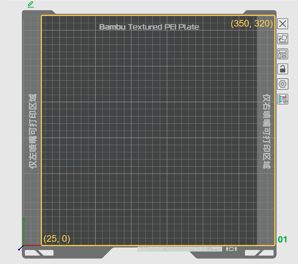
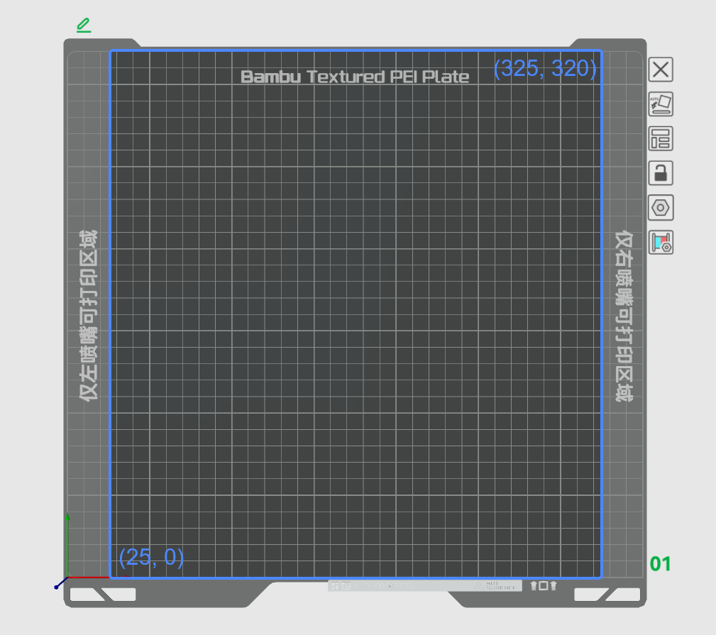
For H2D printers, the full print area in horizontal direction is "325x320". The printable area of the left nozzle is "0x0, 325x320", and the printable area of the right nozzle is "25x0, 350x320". On the Bambu Studio build plate preview, markings on the left and right sides indicate "left nozzle only area" and "right nozzle only area." This means that when the model is placed in this area, only the left or right nozzle can be used for printing. The middle area is the common printing area of the left and right nozzles, as shown in the figures below.
 |
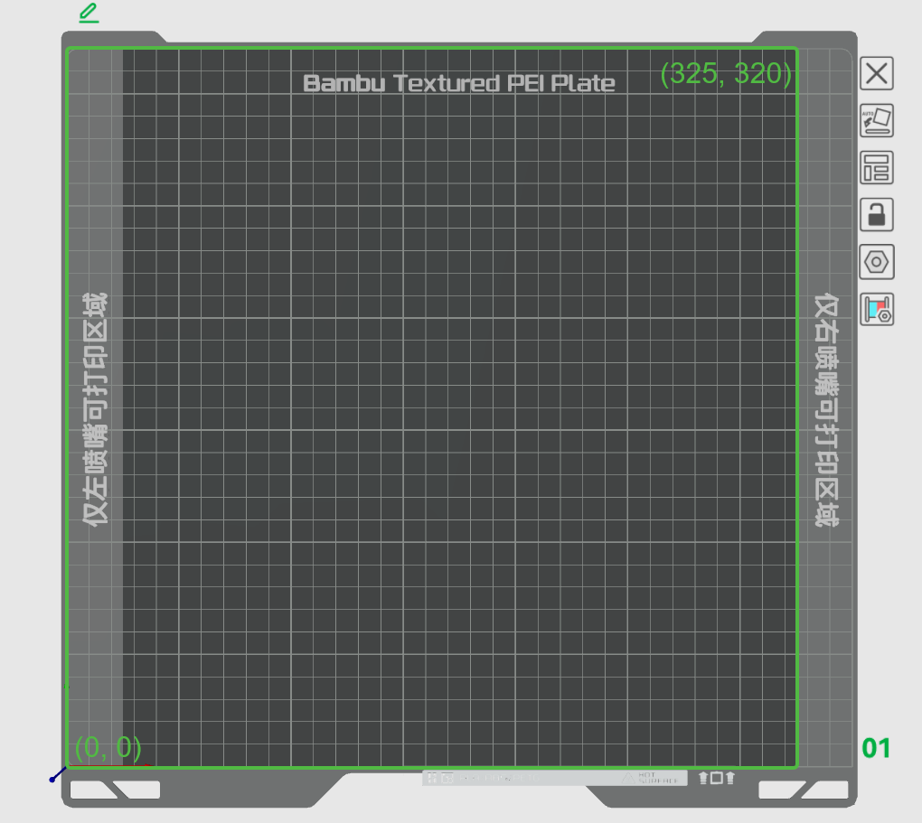 |
| The full print area of the printer | Printable area of the left nozzle |
 |
 |
| Printable area of the right nozzle | Common print area for left and right nozzles |
-
Left nozzle: The maximum printable area in the horizontal direction is 325x320mm²; the maximum printable height is 320mm; the maximum printable volume is 325x320x320mm³;
-
Right nozzle: The maximum printable area in the horizontal direction is 325x320mm²; the maximum printable height is 325mm; the maximum printable volume is 325x320x325mm³;
-
Common print area for left and right nozzles: 300x320mm²; the maximum printable height is 320mm; the maximum printable volume is 300x320x320mm³;
-
Printer: The maximum printable area in the horizontal direction is 325x320mm²; the maximum printable height is 325mm; the maximum printable volume is 325x320x325mm³.
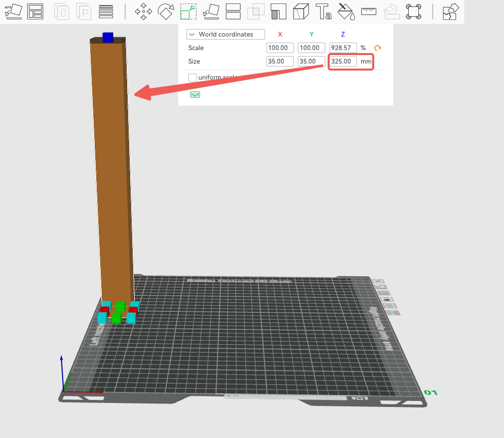
¶ Vertical printable height
The maximum printable height of the left nozzle is 320mm, and the maximum printable height of the right nozzle is 325mm, so 325mm is also the maximum height that the printer can print. When the object is placed within the left-nozzle-only area, its maximum printable height will be slightly lower than the maximum printable height of the printer. Note that if the model height exceeds the printable height of the left nozzle (e.g. 324mm), then the model can only be printed with the right nozzle, even if it is placed in the middle area.
 |
 |
| Maximum printable height of left nozzle | Maximum printable height of right nozzle |
¶ Printable range detection and common error scenarios
When an object is placed in the non-printable area of the left/right nozzle, the sliced filament used by the object can only be printed using nozzles that meet the printing range. The filaments used by this object include: its default filament, the filament used for painting, the filament used for modifiers, and the filament used for height range modifiers.
For example, the cube in the following figure only has one surface painted. From the model surface, this painted surface is the common printing area of the left and right nozzles, but after slicing, due to the embedding of the multi-color area, the print route appears in the left-nozzle-only area. In this case, the default filament of the object, as well as the filament used for painting, can only be printed with the left nozzle.
 |
|
If Bambu Studio detects that the model's placement conflicts with the printable area, or that there may be a conflict, a tip will pop up. Tips are classified into warning tips and error tips. If a warning is displayed, you can continue to slice and send print task, but you may need to adjust the model's placement or the filament. If you get an error message, you cannot slice this plate. The specific detection process is as follows:
¶ Inspection before slicing
¶ Horizontal printable area inspection
(1) Auto grouping: (the filament grouping is unknown before slicing, so which nozzle the filament is grouped into has not yet been determined. The auto grouping has two modes: filament-saving mode and convenient mode. For details, please refer to the Wiki: Introduction to Filament Grouping Strategy for Dual Nozzle Printers
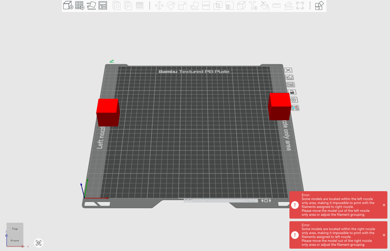
Error: When the same filament appears in both left/right nozzle-only areas, the slicer will give an error message, as shown below.
(2)Custom grouping: (the filament groups have been manually set before slicing. After determining the filament grouping, it can be clearly judged whether the model is placed within the printable range.)
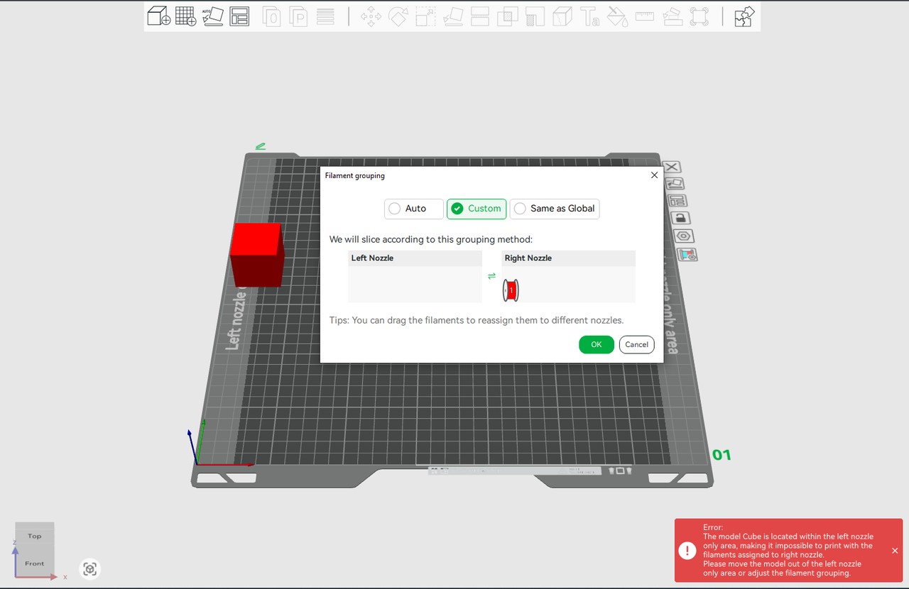
Error: When the model is placed in the non-printable area of the nozzle of the filament group, the slicer will give an error message. For example, in the figure below, the cube is placed in the left nozzle-only area, but the red filament is manually grouped to the right nozzle, and the slicer will directly display an error message.
¶ Vertical printable area inspection
As described above, the printable height of the left nozzle is 320mm, and the printable height of the right nozzle is 325mm.
(1) Auto grouping:
Error: If the model exceeds the maximum printable height of the printer (325mm), both nozzles cannot print and the slicer will give an error message.

(2)Custom grouping:
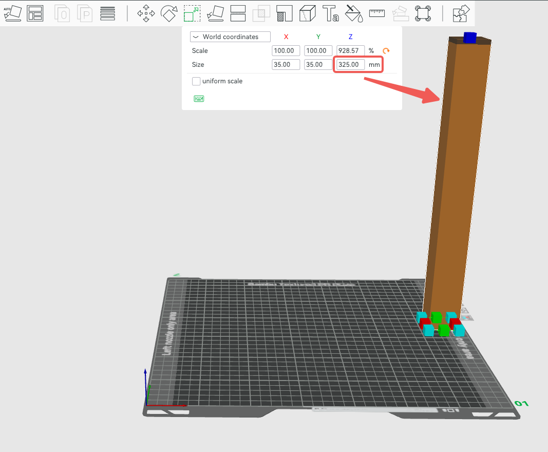
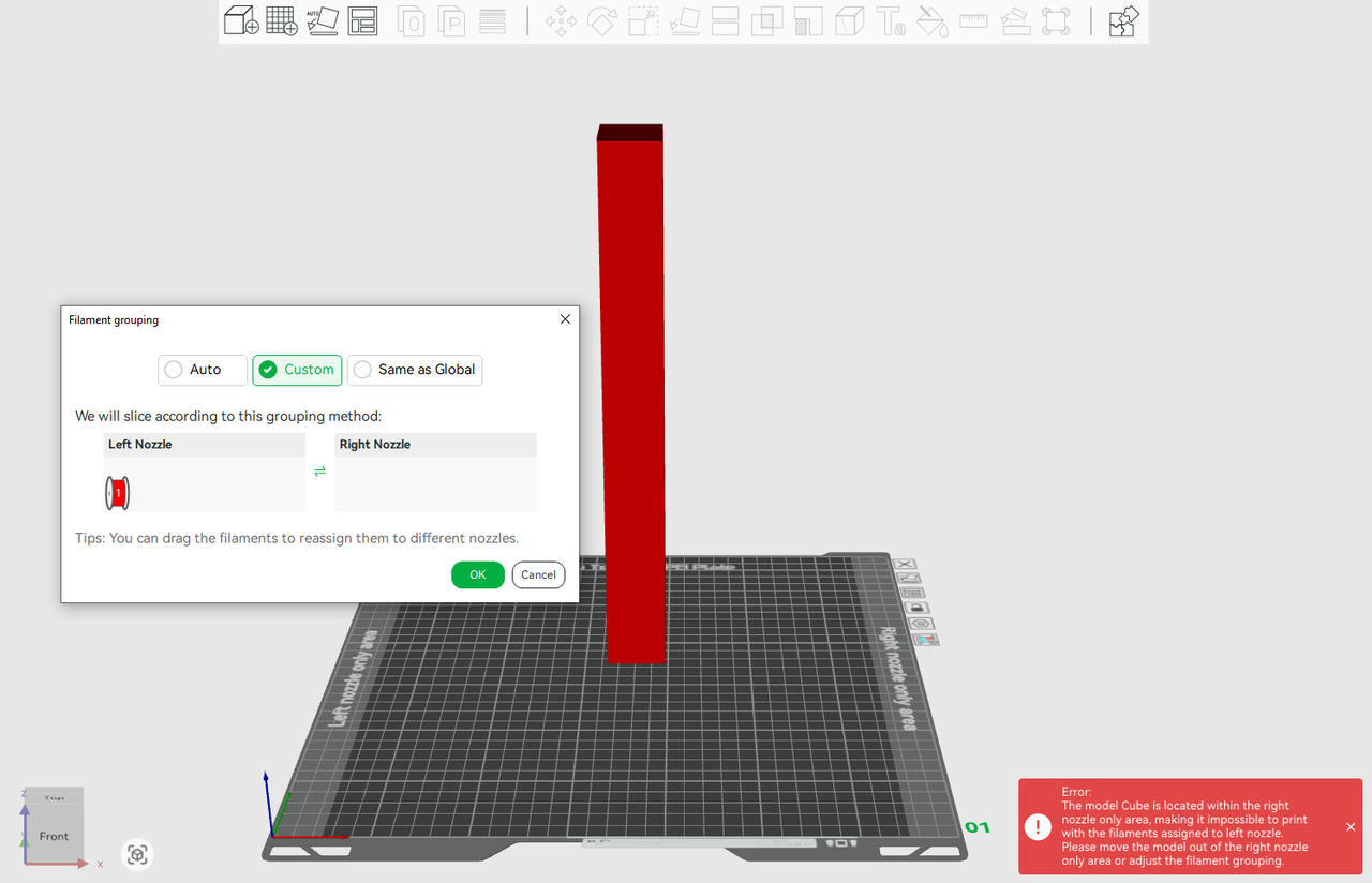
Error: When the model height exceeds the maximum printable height of the left nozzle (320mm) but is lower than the maximum printable height of the right nozzle (325mm), and the filament is manually grouped into the left nozzle, an error message will appear. Suggest appropriately grouping the filament into the right nozzle or adjusting the model height.
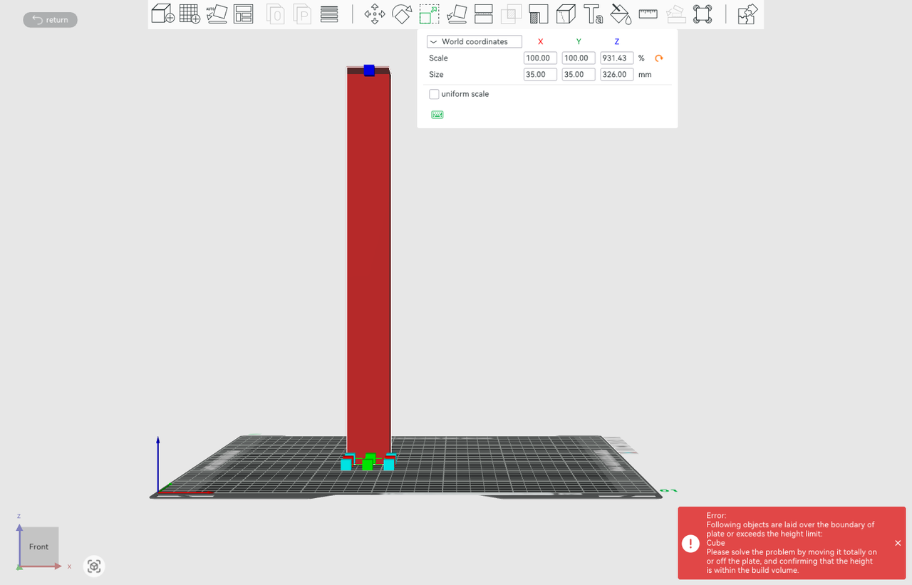
Error: If the model exceeds the maximum printable height of the printer (325mm), both nozzles cannot print and the slicer will give an error message.
¶ Gcode check after slicing
Some scenarios require slicing before it can confirm whether the Gcode path conflicts with the printable range, such as when an object needs to generate support or when flushing to infill/object/support is enabled for a certain object. After slicing, the final nozzle grouping of each filament is determined, and the GCode will be checked to see if it extends beyond the printable area of the nozzle group where the material is located.
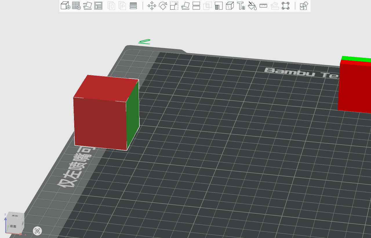
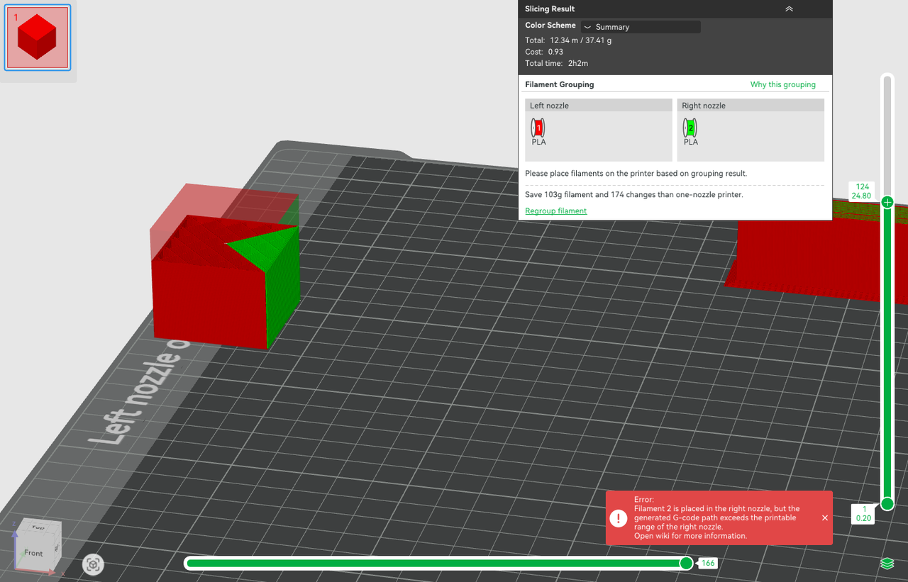
As shown below, the red and blue cubes are placed in the left-nozzle-only and right-nozzle-only areas. After slicing, the two filaments are also grouped to the left and right nozzles (using the filament-saving mode). Enabling "Flush into objects' infill" for the red cube in the object list will allow some flushing blue filament to be printed in the red cube's infill, while the blue filament can only be printed with the right nozzle. Therefore, the Gcode path of the blue filaments exceeds the printable area of the right nozzle, and an error message will appear in the lower right corner.
¶ Common error scenarios
To sum up, the common errors caused by objects beyond the printable range are as follows:
- The default material of the object is in an unprintable area.
For example, the default filament for an object is the filament from the right nozzle, but the Gcode path for the model appears where the right nozzle cannot print.
- For the painted object, the embedded part of the painted area appears in the non-printable area of a certain nozzle.
As shown below, from the appearance, the green part is not located in the non-printable area of the right nozzle. However, looking at the inner layer after slicing, it can be found that due to the embedding of the multicolor area, the Gcode of the green material appears in the non-printable area of the right nozzle.

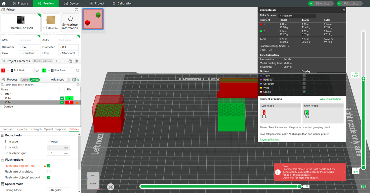
- "Flush to support or infill" is enabled, causing the Gcode path to exceed the printable area of a certain nozzle.
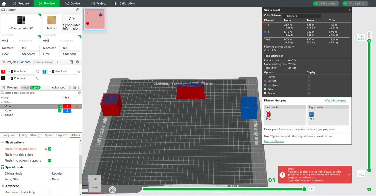
As shown in the figure below, filament 1 is grouped to the left nozzle, filament 2 is grouped to the right nozzle, and filament 1 and filament 2 are located in the printable area of the left and right nozzle respectively. It seems the setting is reasonable, but the error message in the lower right corner shows that the filament 2 Gcode path exceeds the printable area of the right nozzle. This is because we enabled "Flush into objects' infill" in the object list, resulting in the infill of the left cube being printed using filament 2. So there is a conflict between filament 2 (print by right nozzle) and the printable area.
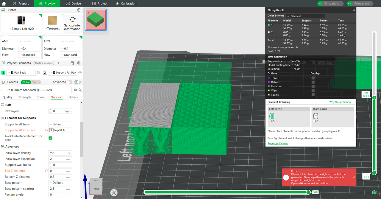
- The filament used for support is located in the non-printable area.
After slicing, if the object has generated support, check whether the filament used for the support and support interface exceeds the printable range of the nozzle. As shown below, the Gcode path for the support filament used by the support interface is partly located in the left-nozzle-only area, resulting in an error message.
¶ End Notes
We hope the detailed guide provided has been helpful and informative.
If this guide does not solve your problem, please submit a technical ticket, we will answer your questions and provide assistance.
If you have any suggestions or feedback on this Wiki, please leave a message in the comment area. Thank you for your support and attention!