¶ Why Calibrate Material Parameters?
In the field of 2D fabrication, the variety of materials is vast, and the built-in material parameters in the software often cannot fully cover all material properties. For example, even a common material like 3mm basswood can vary significantly between manufacturers regarding raw material texture, moisture content, density distribution, and grain structure. These differences directly affect the laser ablation results. Similarly, in blade cutting processes, not only do materials from different batches exhibit varying machining characteristics, but the blade itself also gradually wears over time, requiring dynamic adjustments to the machining parameters for the same material.
To address these challenges, Bambu Suite has developed a Material Calibration Array feature, which effectively solves optimization problems in the following typical scenarios:
-
New Material Adaptation: When encountering a new material not included in the material library, calibration can determine the optimal machining parameters.
-
Batch Variation Adjustment: For materials already in the library but with different batch characteristics, optimize existing parameters to achieve better results.
-
Blade Wear Compensation: When blade wear from prolonged use leads to declining machining quality, recalibrate parameters to maintain consistent performance.
This feature significantly enhances the device's adaptability to different material properties, ensuring stable and reliable machining quality.
In addition, to help users better manage custom materials and the results of calibration, we have developed a comprehensive material input workflow for Bambu Suite.
This guides users through the entire process—from creating a calibration matrix to inputting processing parameters and uploading calibration images. As a result, when using custom materials, users can easily select processing parameters by simply clicking on a block in the calibration map, achieving a "what you see is what you get" experience similar to using official filaments.
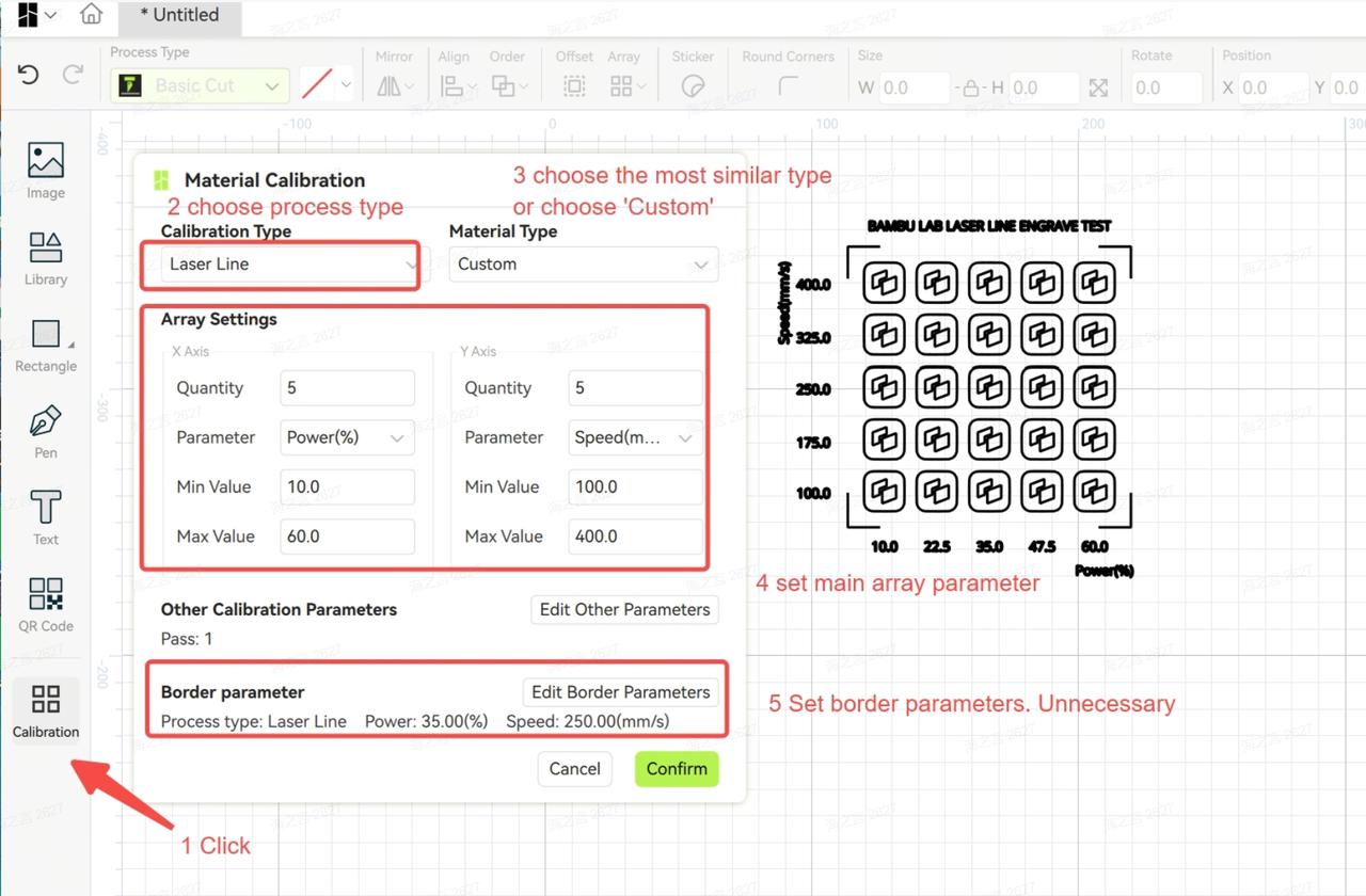
¶ Calibration Matrix Generation
The material parameter calibration feature is located on the left side of the software interface. The software automatically generates a calibration matrix within preset parameter ranges, with each pattern in the matrix corresponding to a set of gradually changing parameters. After fabrication, users can select the most ideal pattern parameters based on the results and save them as new material parameters or update existing ones.
Notes:
-
If no object on the canvas is selected, the software will use the default calibration pattern to generate the matrix.
-
If a pattern on the canvas is selected before clicking the calibration icon, the software will use that pattern as the basis for the calibration matrix.
-
It is recommended to use the default calibration pattern to ensure accuracy and consistency.
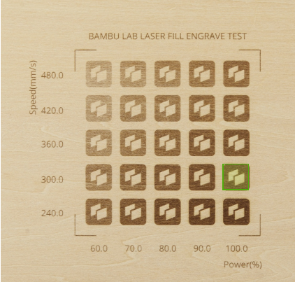
After the matrix processing is completed, a calibration board like the one below will be produced (The illustration shows the calibration results on a bamboo board using the laser fill process, with different combinations of speed and power).
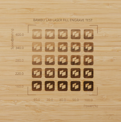
Please refer to [Additional Info] section for the calibration matrix for different processings.
¶ Material Calibration Input Workflow
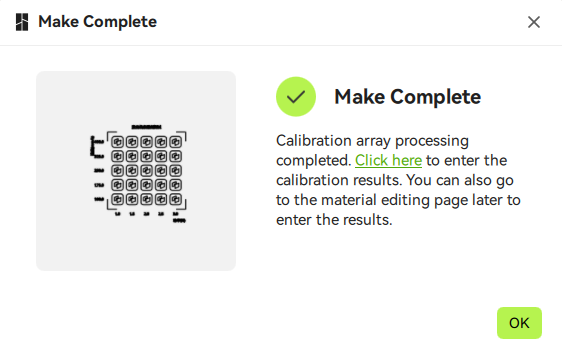
Through this workflow, Bambu Suite saves the parameters and calibration images set during material calibration, while also recording the optimal processing parameters.
After the calibration matrix is completed, Bambu Suite prompts the user to save the data. Clicking "Click here" will begin the material input process.
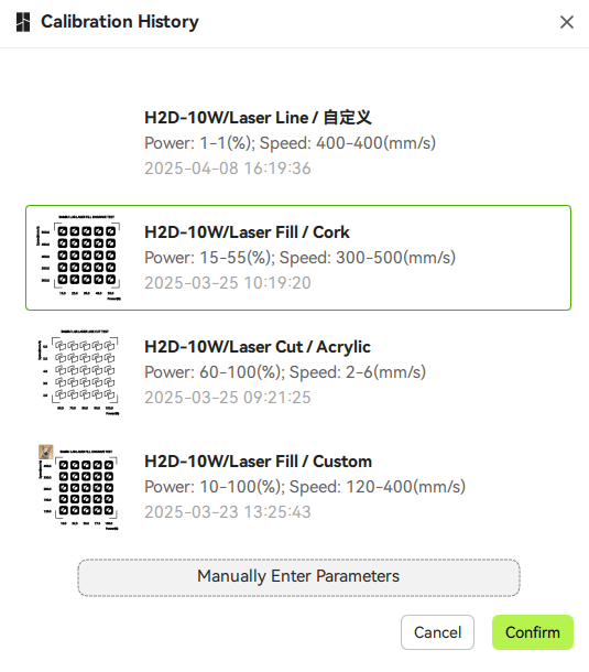
Additionally, users can also find the material input workflow from the calibration matrix history as shown below.
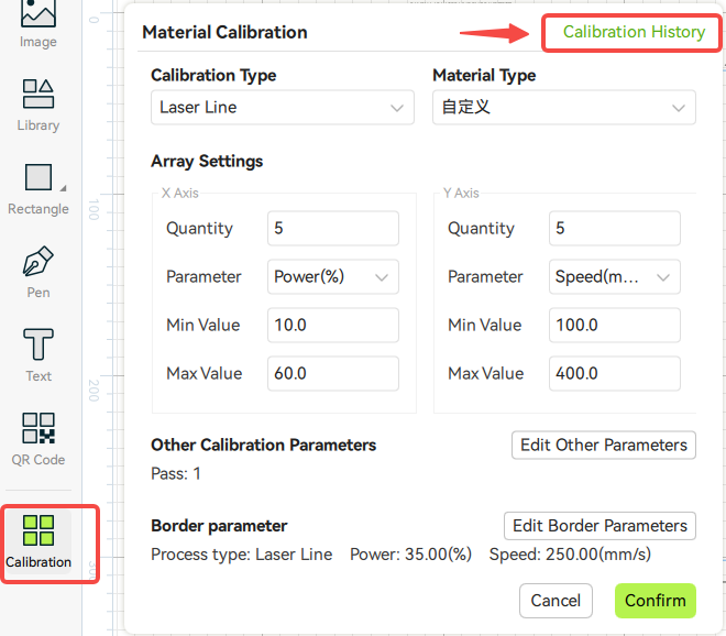
At this point, Bambu Suite will display the previously calibration matrixs. Users only need to select the corresponding processing history to import the configured parameter values with one click.
Each time a user processed a matrix, its data will be saved here.
When no history is available, users can manually enter the calibration data for the matrix.
We recommend users perform calibration individually for each machine, rather than sharing calibration results across multiple machines, to achieve the best results.
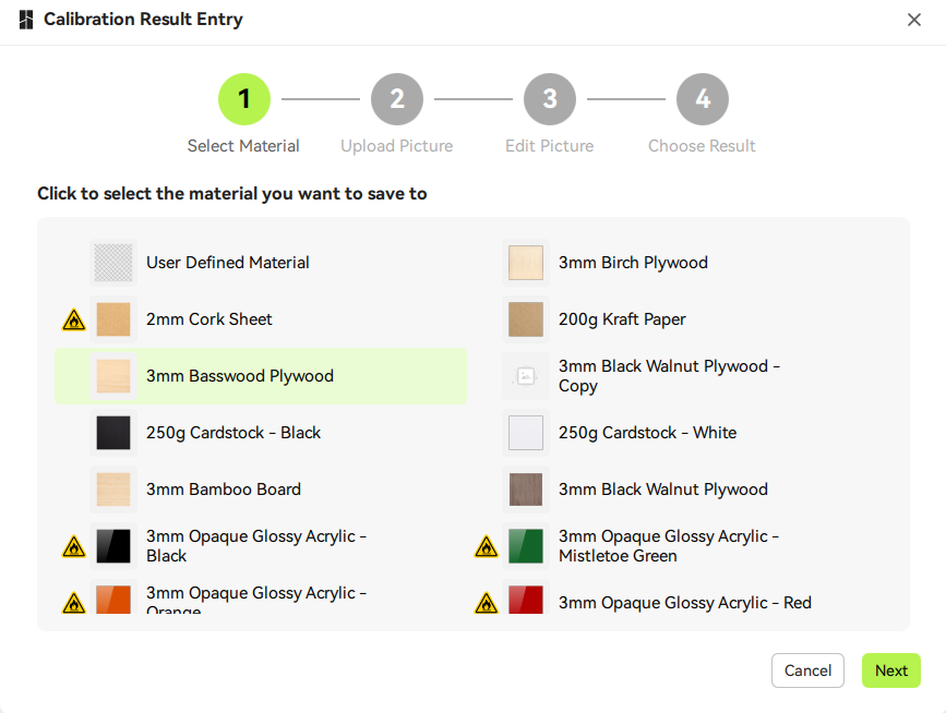
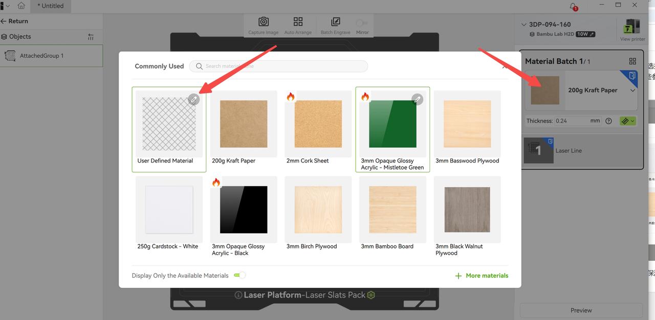
After selecting a calibration history, the next step is to choose which material to apply the calibration matrix to.
Here, users can save the calibration image and results into a custom material or a copy of an official material.
Note: If an official material is selected, this will not overwrite the data of the official material. Instead, it will create a copy of the material. After the calibration results are recorded, you can go to the Material Management page to edit the name and other parameters.
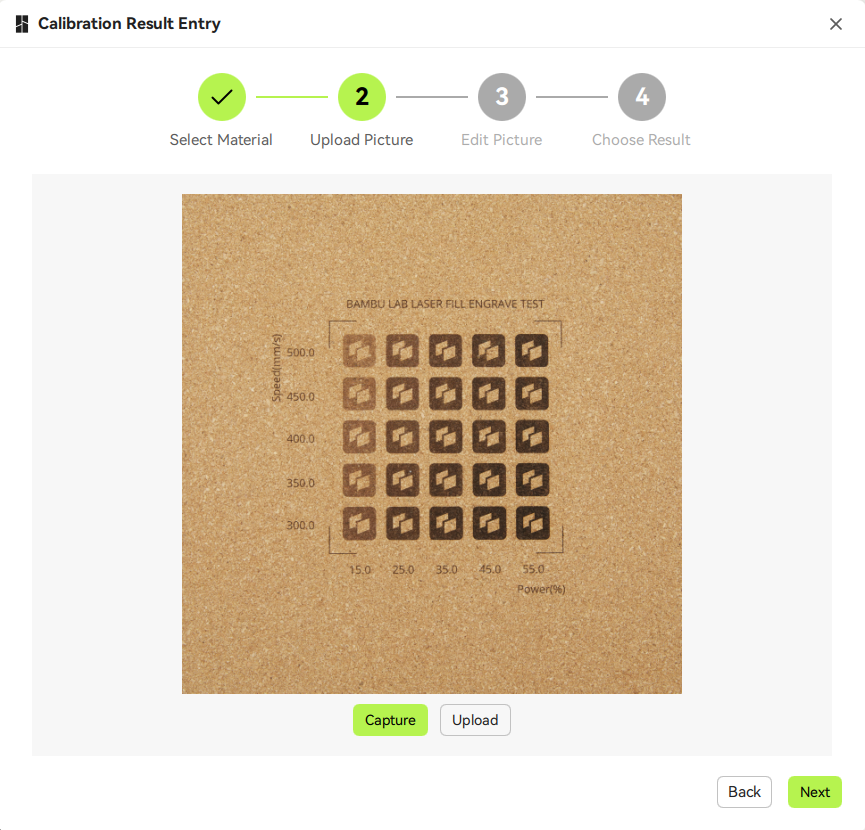
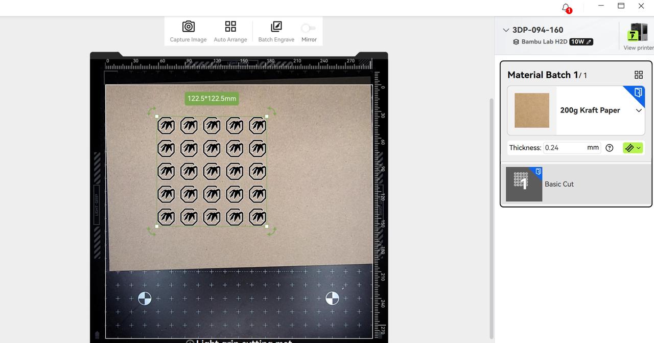
(Laser Only) Click "Next" to start uploading images or take a photo. Users can place the calibration board inside the machine and click "Take Photo" to capture an image using the machine’s birdeye camera.
For users with higher image quality requirements, we recommend using professional photography equipment and uploading the image via the "Upload" function.
At this step, just ensure the image is roughly taken from a straight-on perspective.
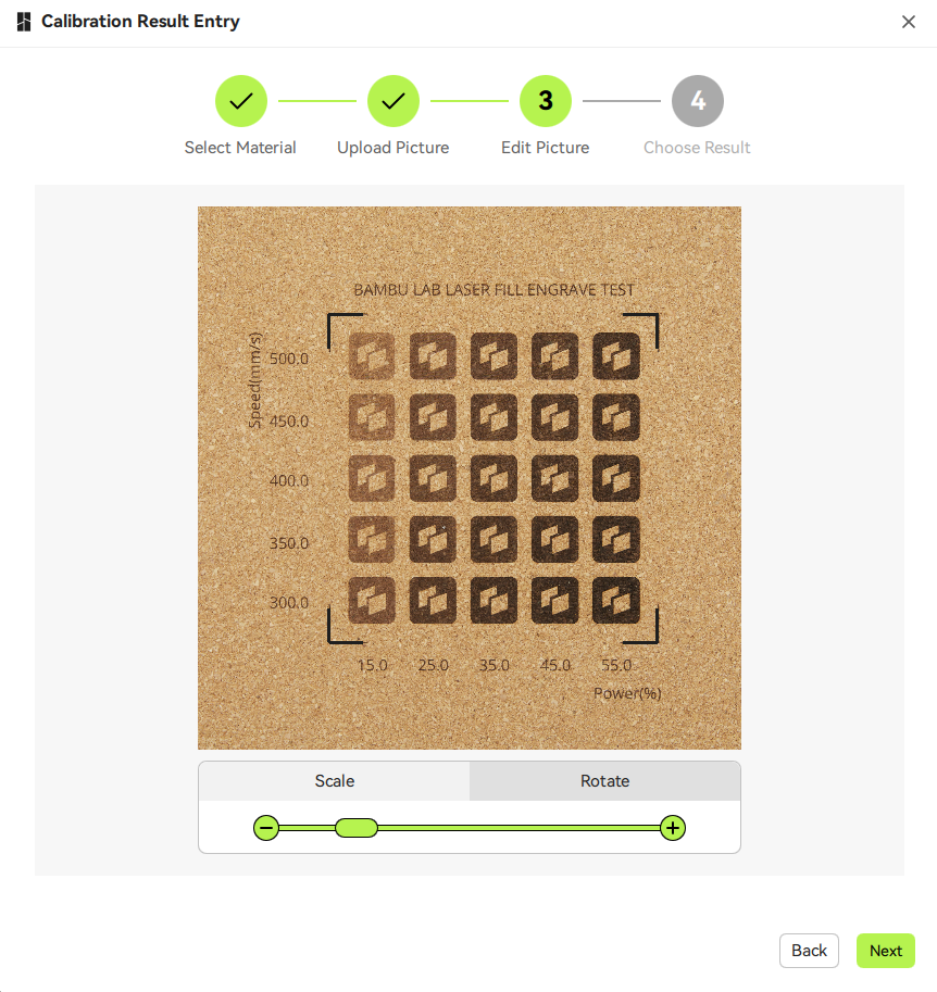
(Laser Only) Click "Next" and Bambu Suite will use its smart image correction feature to crop and process the calibration matrix area, producing a perfect top-down corrected view.
Note that only one calibration matrix is allowed in the field of view at a time.
If multiple matrices are on the same material, cover the unrelated ones with paper or other objects, or take a photo of only the relevant matrix.
(Laser Only) If the image does not contain a calibration matrix, the matrix markers are unclear, or multiple matrices are detected, the automatic image processing may fail.
Please retake the photo or fine-tune the matrix engraving parameters to ensure the markers are clearly engraved.
If a matrix cannot be clearly engraved, users can use rotation and scaling tools to manually align the matrix until the markers match the expected layout.
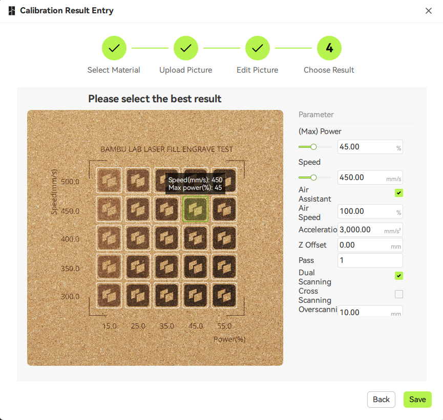
Click "Next", and Bambu Suite will display the recognized parameter grid and draw the parameters for each block on screen.
Users only need to select the corresponding block on the canvas to set it as the default processing parameter.
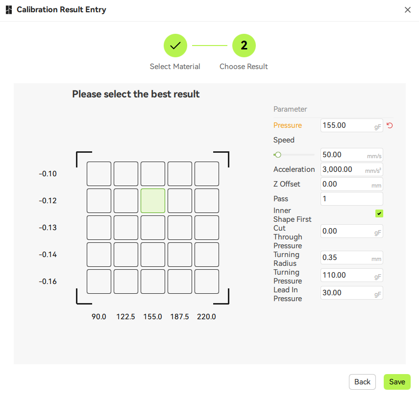
For basic cutting (non-laser), since no image is uploaded, Bambu Suite will display a virtual grid.
Users can refer to the actual cut sample and select the virtual grid cell that corresponds to the best physical result to automatically input the parameters.
After confirming the information is correct, click "Save" to complete the input of the calibration matrix image and default processing parameters.
In future processing, selecting the material you just entered will allow you to quickly configure the processing parameters by clicking on the image.
For editing material name, processing type, and other parameters, please go to the Material Management page for detailed settings.
Calibration images can also be reconfigured and edited from the Material Management page.
¶ [Additional Info] Matrix for Different Type of Processings
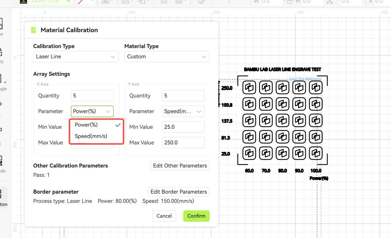
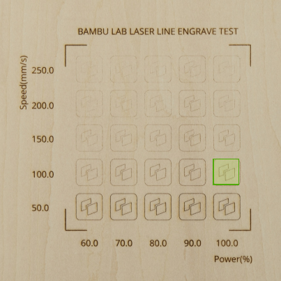
¶ Laser Line Engraving/Cutting Parameter Calibration
For laser line engraving and cutting, the core machining parameters are laser power and processing speed. The calibration matrix's X and Y axes correspond to these two parameters. Users can set the number of calibration blocks for each axis: more blocks result in finer parameter gradients but longer processing times.
¶ Calibration Steps:
-
Generate Calibration Matrix: Set the parameter range and click "Prepare."
-
Select Material: Choose a material similar to the one being calibrated (e.g., 250g cardstock for paper materials). This step mainly determines non-calibration parameters (e.g., air pump, acceleration) required for generating G-code, which typically do not significantly affect calibration results.
-
Positioning and Focusing: Place the calibration pattern on the material, perform photo positioning and thickness measurement, and ensure the laser is properly focused.
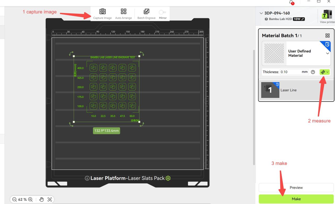
-
Start Processing: Begin the process to complete the calibration matrix.
¶ Result Selection:
-
For laser line engraving, choose a pattern with moderate grayscale.
-
For laser line cutting, select a pattern that just cuts through the material.
-
Match the corresponding laser power and speed parameters based on the selected block's row and column to obtain the optimal machining parameters for the material.
Through these steps, users can efficiently and accurately complete material parameter calibration to achieve optimal machining results.
¶ Calibrating Laser Fill Engraving Parameters
The process for calibrating laser fill engraving power and speed is similar to that of line engraving/cutting. However, laser fill engraving includes an additional parameter: scanning interval, which controls the distance between fill scan lines:
-
If the scanning interval is too dense, the engraved area may appear too dark.
-
If the scanning interval is too sparse, the engraved area may appear too light.
Since different lasers have varying spot sizes and materials absorb energy differently, the scanning interval significantly affects the grayscale results of fill engraving.
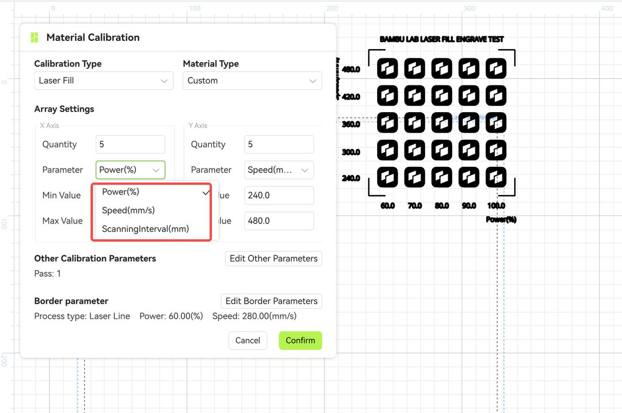
The fabrication process after generating the calibration matrix is largely the same as described earlier. After completion, select the parameters corresponding to a block with moderate grayscale and no noticeable gaps between scan lines.
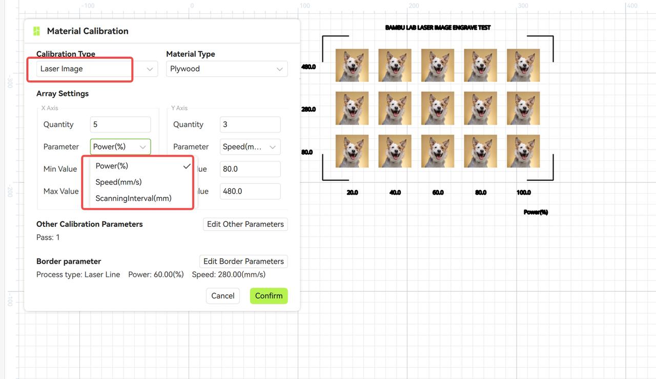
¶ Calibrating Laser Image Engraving Parameters
When using a laser for image engraving, the machining results are primarily determined by power, speed, and scanning interval. The laser image calibration feature allows you to test engraving effects at different power levels. After completion, select the image with the best visual quality and use its corresponding parameters for formal image engraving.
¶ Calibrating Blade Cutting Parameters
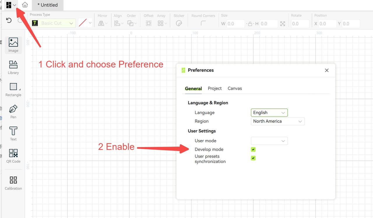
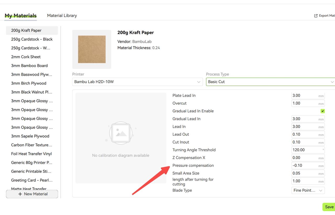
In blade cutting, blade pressure is a key parameter affecting cutting quality. If the cutting results are unsatisfactory or the material is not fully cut, blade pressure calibration is recommended. Blade pressure calibration involves two parameters: blade pressure and pressure compensation (the latter requires unlocking advanced parameters in developer mode).
¶ Calibration Steps:
-
Select Calibration Type and Material:
-
Choose Basic Cut as the calibration type.
-
Select a material type similar to the one being processed; if no suitable option exists, choose Custom.
-
Note: If unsure about the material type, estimate the blade pressure range based on material thickness and gradually increase from low to high pressure.
-
-
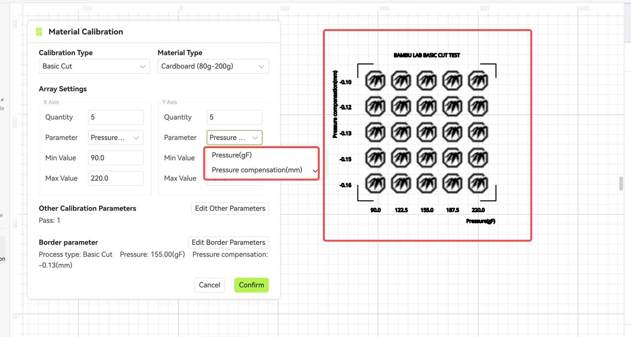
Set Calibration Parameters:
-
Select Pressure and Pressure Compensation as the parameters.
-
Click "Confirm" to generate the blade pressure calibration matrix.
-
-
Prepare and Fabricate:
-
Enter the preparation interface and select a similar material type or custom type.
-
Start fabrication to complete the calibration matrix cutting.
-
¶ Result Analysis and Selection:
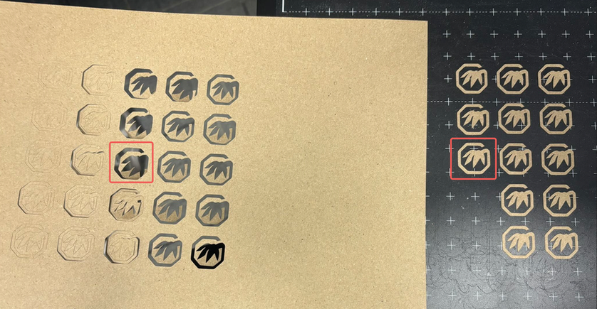
After cutting, select the appropriate parameters based on the cut-through results. For example:
-
Columns 1-2: Not cut through, indicating low blade pressure.
-
Column 3: Partially cut through, indicating optimal blade pressure.
-
Columns 4-5: Fully cut through, but the blade pressure may be too high, potentially damaging the cutting platform.
Optimal Parameter Selection:
Choose the parameters from the third block in Column 3 (from the bottom). These parameters meet the following conditions:
-
The blade pressure is just enough to cut through the material without being too low (incomplete cuts) or too high (platform damage).
-
The cut edges are clean, the platform shows no significant scratches, and the internal and external shapes are intact (corner adhesion is normal).
In the calibration matrix, blade pressure increases from left to right. If all patterns in a column are fully cut through, the blade pressure may be slightly higher than needed. In this case, move back to the previous column, which typically shows a mix of cut and uncut areas. Select the pattern that just cuts through the material and use its corresponding blade pressure and compensation values as the optimal parameters. This method ensures cutting quality while avoiding excessive wear on the blade or cutting platform.
Complex Pattern Cutting Recommendation:
For cutting complex patterns, consider blade wear by multiplying the calibrated blade pressure by a 1.2 aging factor as the actual cutting pressure, while keeping the compensation value unchanged.
¶ Common Issues and Solutions:
-
All calibration blocks are not cut through:
-
Cause: Blade pressure range is too low.
-
Solution: Increase the blade pressure range and recalibrate.
-
-
All calibration blocks are fully cut through:
-
Cause: Blade pressure range is too high.
-
Solution: Decrease the blade pressure range and recalibrate.
-
-
One column is not cut through, while the next is fully cut through:
-
Cause: Blade pressure range is too broad.
-
Solution: Refine the blade pressure range and recalibrate to find the critical value where partial and full cuts occur.
-
Through this calibration process, users can precisely determine the optimal blade pressure parameters, ensuring cutting quality while extending the lifespan of the blade and cutting platform.
¶ End Notes
We hope the detailed guide provided has been helpful and informative.
If this guide does not solve your problem, please submit a technical ticket, we will answer your questions and provide assistance.
If you have any suggestions or feedback on this Wiki, please leave a message in the comment area. Thank you for your support and attention!