¶ Background
Processing parameters are key configuration options in Bambu Suite for generating toolpaths. By using appropriate parameters, you can significantly improve processing quality and achieve desired results. Different materials and processes (e.g., laser line engraving, laser line cutting) require unique parameter configurations. Bambu Suite pre-optimizes parameters for supported materials, ensuring users can start quickly and achieve ideal outcomes.
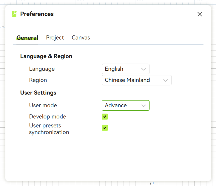
This guide explains how processing parameters affect results and helps you choose the right settings to optimize quality or adjust effects. For ease of use, parameters are categorized into three levels: Basic, Advanced, and Developer. Adjust these levels via Menu > Preferences > User Settings. We’ll also cover parameter applications and setup for Laser Processing, Basic Cutting, and Drawing Processes.
¶ Laser Processing Parameters
¶ [(Max) Power]
The maximum laser output power, set as a percentage. For example, a 10W laser at 50% power outputs 5W.
¶ [Speed]
The toolhead’s movement speed during laser line engraving, in mm/s. Laser power and speed jointly determine processing results. Different combinations produce effects as shown below.
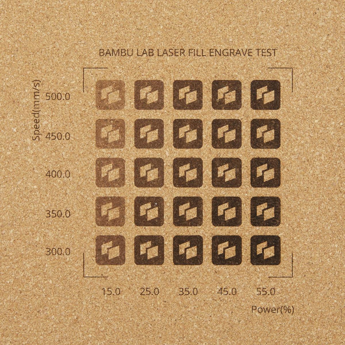 |
 |
¶ [Acceleration]
Controls the toolhead’s acceleration. Lower acceleration reduces noise and vibration but increases processing time.
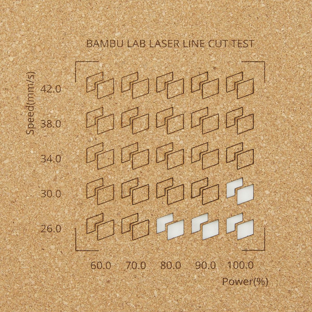
¶ [Pass]
Sets how many times a path is repeated. Use multiple passes for thicker materials to achieve full cuts.
¶ [Air Assistant & Air Speed]
Toggles air assist and sets its speed (100% = max speed). Air assist clears dust during cutting, improving surface clarity and engraving precision.
¶ [Perforation Mode, Perforation Cut, Perforation Skip]
Used for creating dashed-line effects. Perforation Cut sets the length of dashes, while Perforation Skip sets the gap between them.
¶ [Z Offset]
Adjusts the vertical offset of the processing object. Defaults to 0 and usually requires no changes.
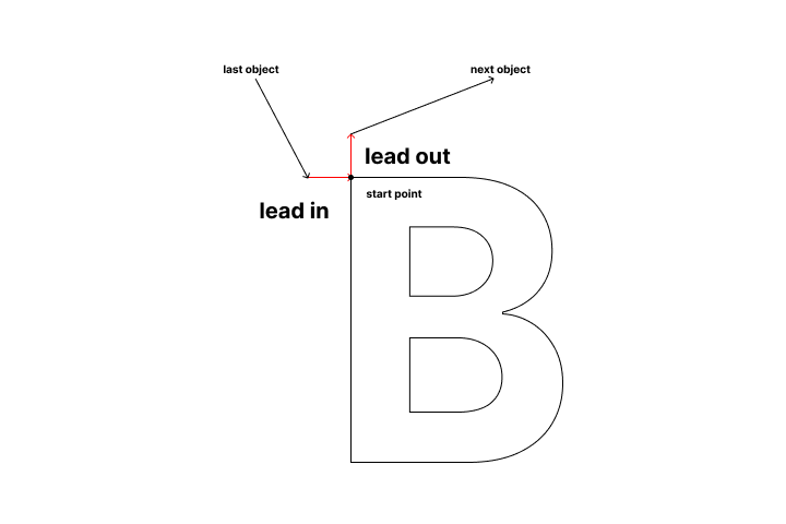
¶ [Lead In & Lead Out]
Adds extended lines at the start and end of a path along its tangent direction. Properly setting these lengths minimizes processing issues caused by abrupt speed changes.
¶ Laser Scanning Parameters
¶ [Dual Scanning]
Controls the laser emission direction during scanning.
-
Off: Laser emits only during forward scanning (no emission during return to start).
-
On: Laser emits in both forward and reverse directions, significantly reducing processing time.
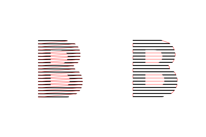
¶ [Cross Scanning]
Scans along both X and Y axes to improve engraving uniformity. Ideal for tasks requiring high consistency. See example results below.

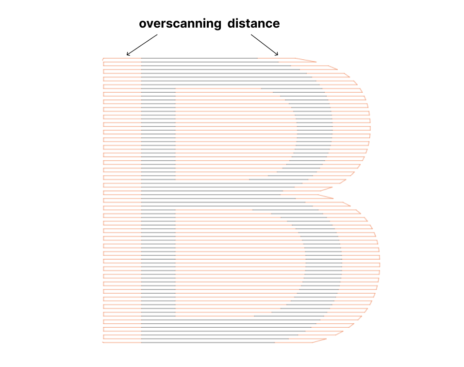
¶ [Overscanning Distance]
Adds non-emitting extension lines at the start/end of each scan row. Reduces uneven engraving caused by abrupt speed direction changes.
¶ [Scanning Interval]
Sets the distance between adjacent scan lines, typically matching the laser spot size.
-
Note:
-
Too small: Overlapping lines darken engraved areas.
-
Too large: Separated lines over-brighten areas.
-
Ideal: Lines touch but do not overlap.
-
¶ [Scanning Angle]
Sets the angle between scan lines and the X-axis (clockwise). Adjust based on material properties and desired effects.

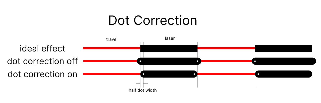
¶ [Dot Correction]
Compensates for laser spot size impact on engraving precision. Enable for high-accuracy tasks.
¶ [Min Power]
Applies only to laser image engraving. Sets the minimum power required for visible engraving. Near-white pixels are mapped to this value.
¶ [Image Mode]
-
Grayscale: Converts images to grayscale, mapping pixel values to power levels between min/max.
-
Threshold: Binarizes images, using only min/max power.
-
Stucki/Jarvis/Bayer/Halftone/Atkinson/Floyd/Sierra: Simulates continuous grayscale with limited levels, preserving details.
¶ [Negative Image]
Inverts image light/dark areas when enabled.
¶ [Grayscale Power Mapping]
Auto-optimizes grayscale engraving using calibration data. Enable for high-precision grayscale tasks.
¶ [Image Gamma]
Adjusts pixel-to-power mapping curves. Affects brightness/contrast in grayscale mode only.
¶ [Clahe Enable, Clahe Limit, Clahe Size]
Enhances contrast via histogram equalization (grayscale mode only).
-
Clahe Limit: Higher values increase contrast.
-
Clahe Size: Larger values apply adjustments more globally.
¶ [Lower Focus Enable, Lower Focus]
Shifts the laser focus slightly below the material surface to improve cutting capability for thicker materials.
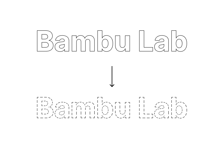
¶ [Spot Correction]
Offsets cutting paths by half the spot size to compensate for precision errors. See diagram below.
.png%3E)
¶ [Cut Offset]
Sets path offset (usually half spot size), similar to Spot Correction.
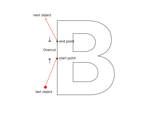
¶ [Overcut]
Extends cutting beyond closed paths to ensure full material penetration.

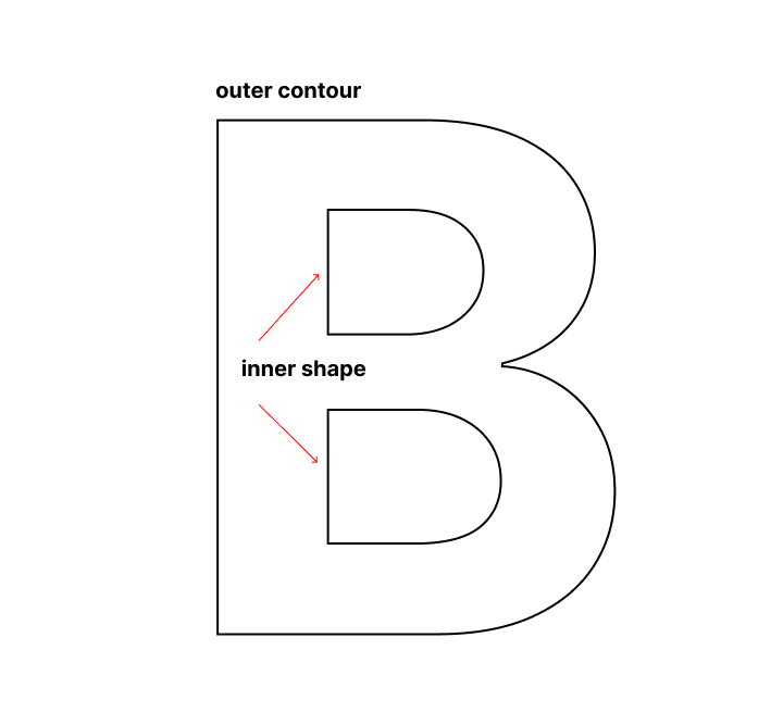
¶ [Inner Shape First]
Prioritizes inner shapes by default. Prevents cut-out outer parts from interfering with inner engraving.
¶ [Start/End Pause Time & Power]
Pauses at path start/end points with specified power to ensure complete cuts, preventing partial cuts from abrupt laser movement.
¶ Basic Cutting Parameters
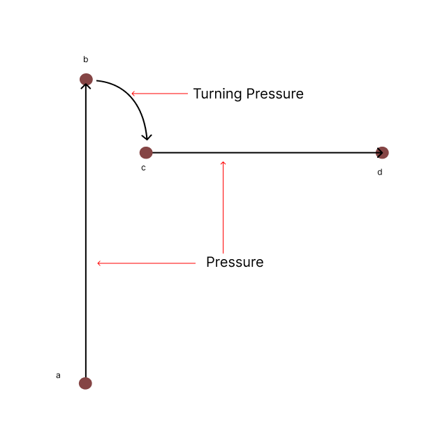
¶ [Pressure]
Sets the downward pressure during cutting, measured in gF (1gF = force exerted by a 1g object under standard gravity).
¶ [Pass]
Sets the number of times the cutting path is repeated. For thicker or harder materials, multiple passes may be needed to achieve full cuts.
¶ [Inner Shape First]
Prioritizes cutting inner shapes by default. If outer shapes are cut first, detached material may shift during inner shape cutting, causing defects or failures. Enabling this avoids such issues.

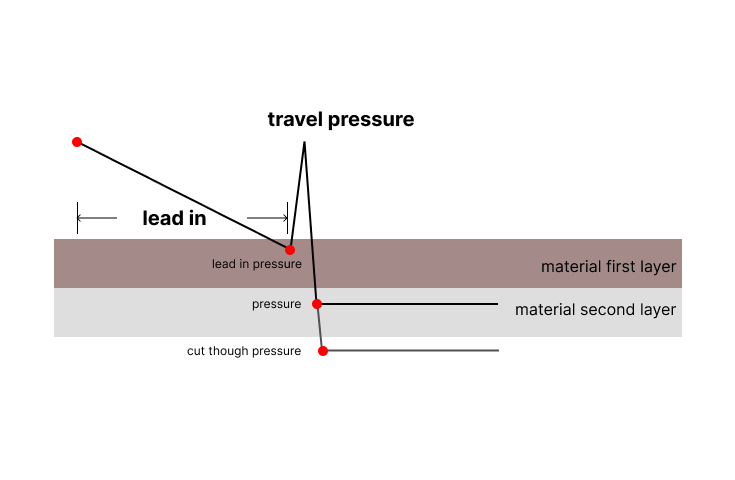
¶ [Cut Through Pressure]
Sets the pressure required to fully cut through materials. Commonly used for multi-layer materials, such as sticker sheets.
¶ [Turning Radius]
Sets the radius for blade turns, typically matching the blade tip offset. Usually, no adjustment is needed.
¶ [Turning Pressure]
Sets the pressure during blade turns, usually lower than normal cutting pressure.
¶ [Lead In Pressure]
Sets the pressure when the blade reaches the cutting path start point. The lead-in process gradually increases pressure:
-
Start: No pressure during traveling.
-
Lead-In: Pressure increases along the lead-in path (pre-entry path before cutting). At the start point, pressure reaches the set Lead In Pressure, and the blade aligns with the cutting direction.
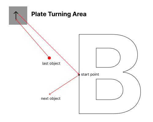
¶ [Plate Turning, Plate Turning Pressure, Plate Leadin]
Plate Turning: Adjusts the blade direction on the cutting plate instead of the material surface to avoid leaving marks. This improves cutting quality but increases processing time.
-
Plate Turning Pressure: Pressure applied during toolhead direction adjustment on the cutting plate.
-
Plate Leadin: Distance the toolhead travels on the plate during direction adjustment.
¶ [Overcut]
Extends cutting beyond closed paths to ensure full material penetration.
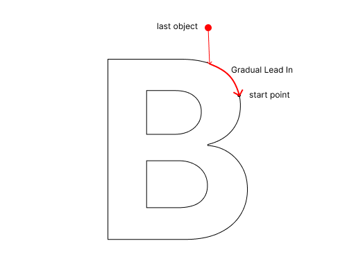
¶ [Gradual Lead In Enable, Gradual Lead In]
Add a pre-path segment before the starting point. The blade gradually increases pressure and adjusts direction while moving along this path. This reduces cutting flaws caused by abrupt direction changes and improves processing quality.
¶ [Lead In, Lead Out, Cut Inout]
¶ Lead In
-
Purpose: The blade "backs up a short distance" before cutting to align its direction with the processing path.
-
Process:
-
Starts cutting from the reverse side of the path’s starting point.
-
If the current path direction matches the previous one, use the shorter Cut Inout distance.
-
If directions differ significantly, use the longer Lead In distance for smoother adjustment.
-
¶ Lead Out
-
Purpose: The blade "travels an extra distance" after cutting to prevent material tearing or burrs from abrupt stops.
-
Process: After completing the path, the blade continues moving along the original direction for the Lead Out distance before lifting off.
¶ Cut Inout
-
Purpose: Smoothly connects paths with similar directions, minimizing repeated toolhead adjustments.
-
Use Case: When adjacent paths share the same or similar directions, Cut Inout ensures seamless transitions without major adjustments.
.png%3E)
¶ [Z Compensation X, Z Compensation Y]
Adjusts Z compensation for X and Y axes to achieve consistent cutting results under the same pressure.
¶ [Small Area Size]
Sets a size threshold; objects smaller than this in both length and width are ignored. Improves efficiency by avoiding poor cuts on tiny objects due to precision limits.
¶ Drawing Parameters
¶ [Draw Direction]
Sets the drawing path direction:
-
No Limit Drawing Direction: Automatically selects the nearest path.
-
Handwriting Drawing Direction: Draws paths from top to bottom and left to right.
¶ [Drawing Endtype]
Supports two end types:
-
Normal Drawing Endtype: Lifts the pen after completing closed shapes.
-
Sharp Drawing Endtype: Lifts the pen early at the end of closed shapes, creating a sharp angle to reduce ink smudging at the start point (ideal for watercolor pens).