¶ When to use ?
When a deviation occurs during the filament change and cutting process of the printer, it may be caused by tooth jumping in the gear within the filament cutter stopper assembly. In this case, it is necessary to open the cutter stopper assembly for adjustment.
If tooth jumping occurs on the filament cutter stopper during initial use, it may be caused by accidental impact during unboxing. Please refer to the quick repair guide below for resolution.
¶ Quick Repair Guide
 |
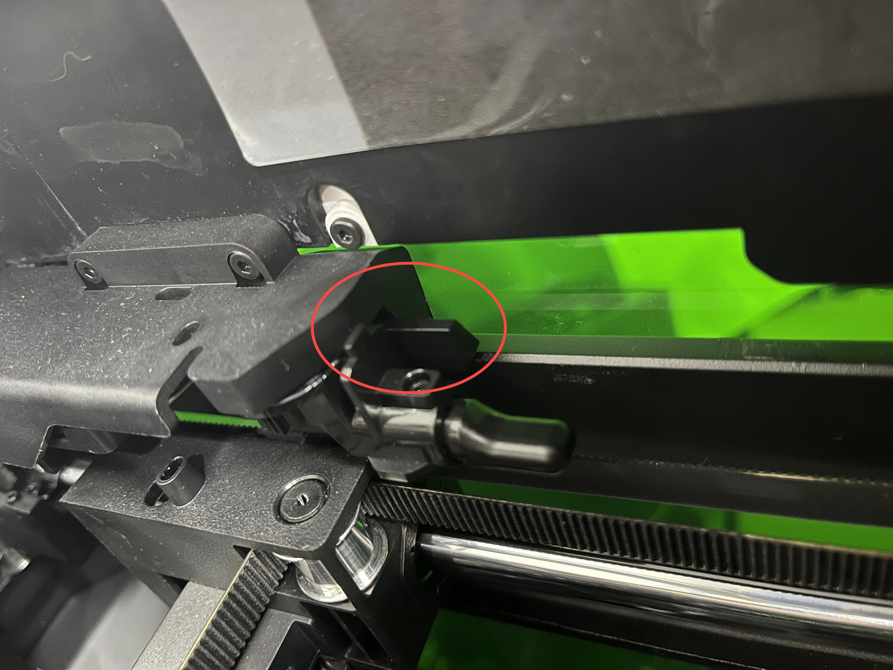 |
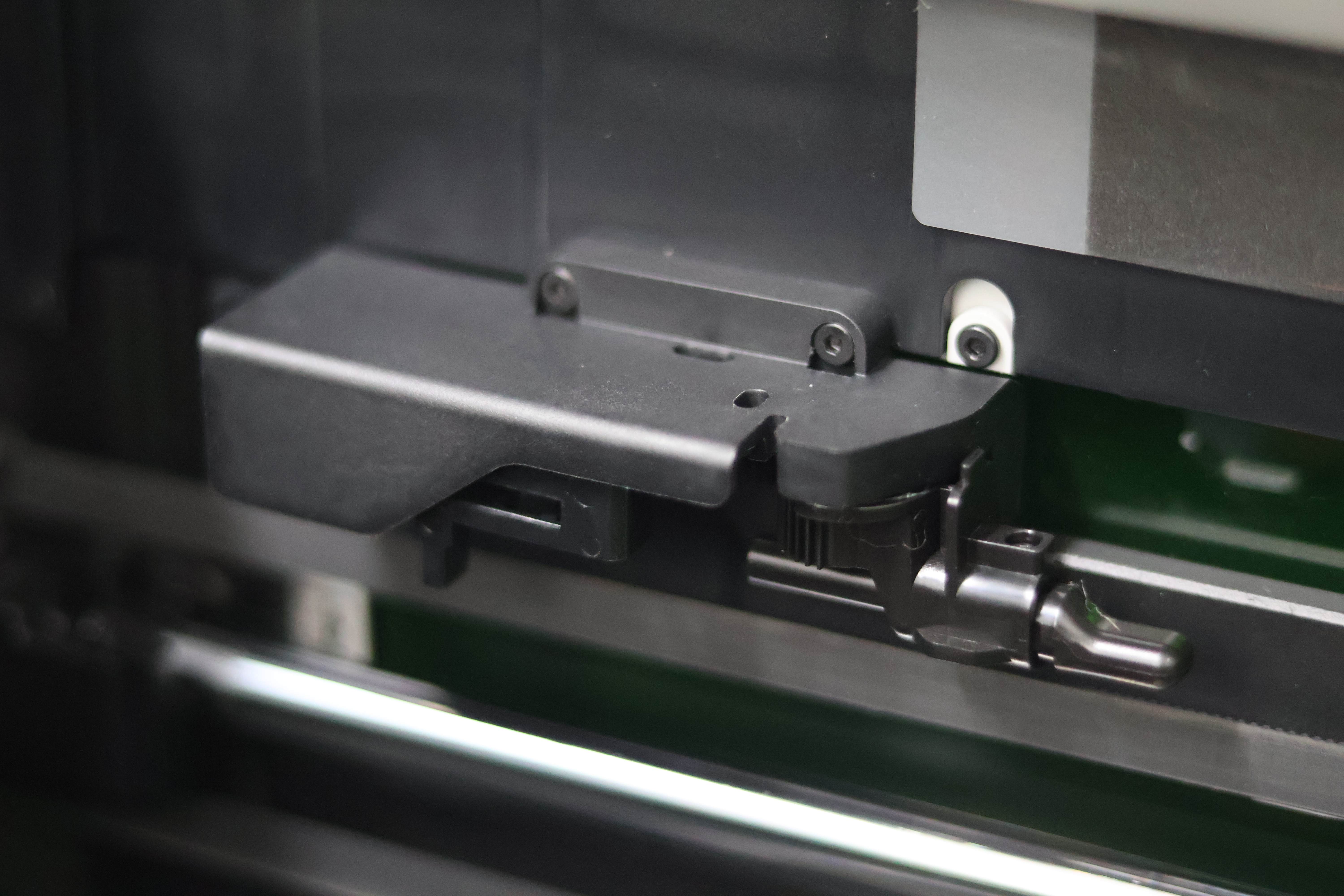
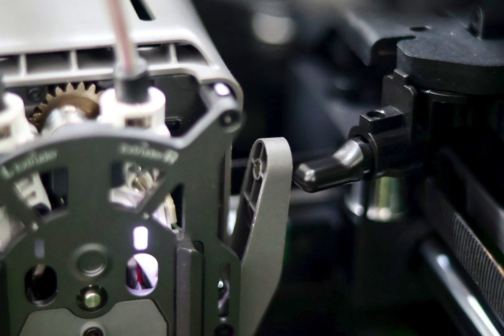
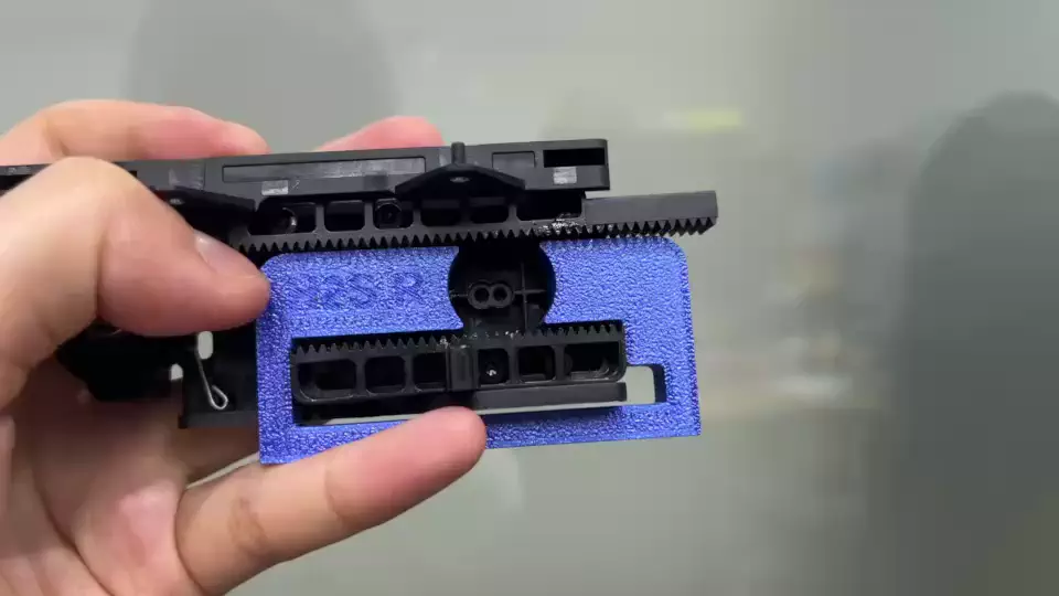
| Normal State: When the cutter rod is horizontal, the rack and the end of the stopper block are flush. | Abnormal State: When the cutter rod is horizontal, the rack protrudes beyond the end of the stopper block by a certain length. |
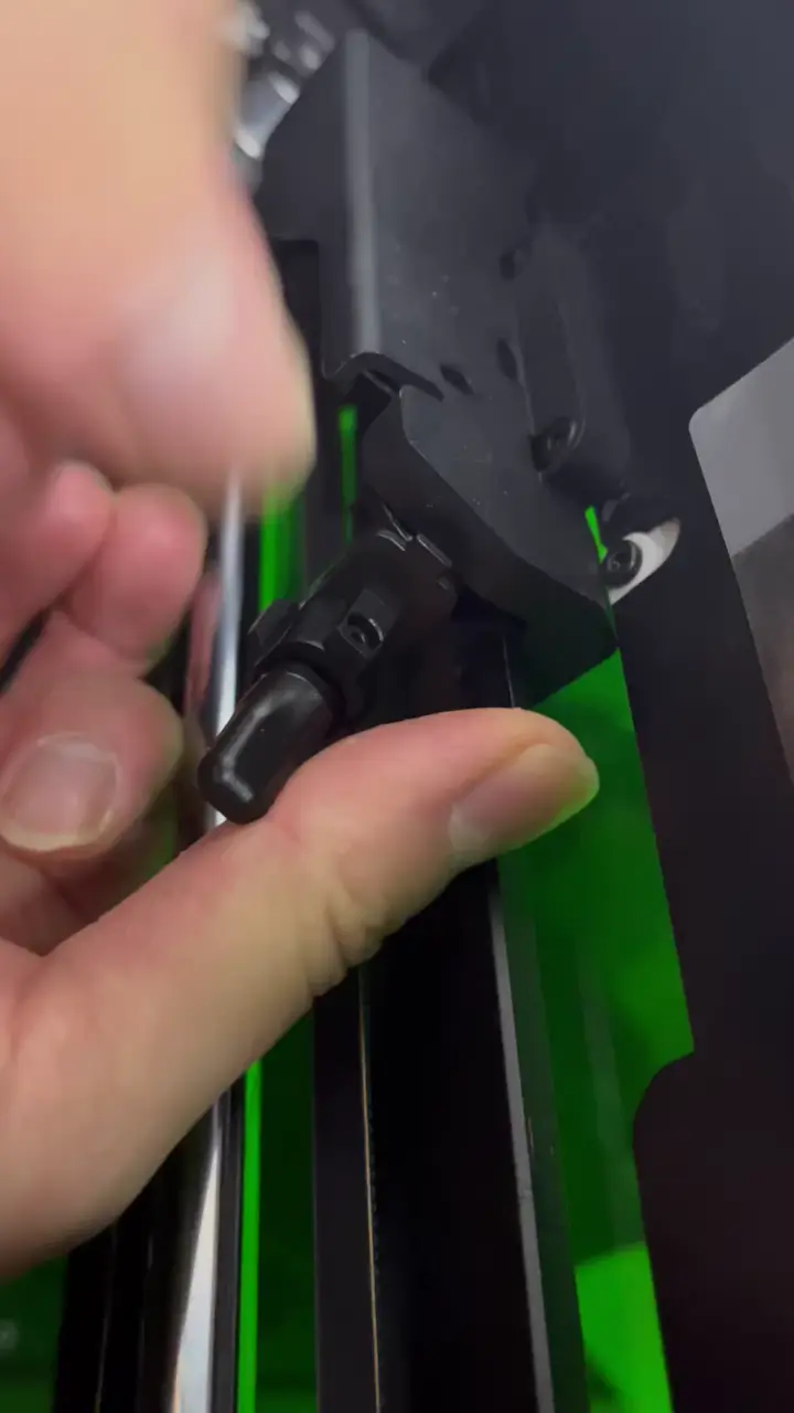
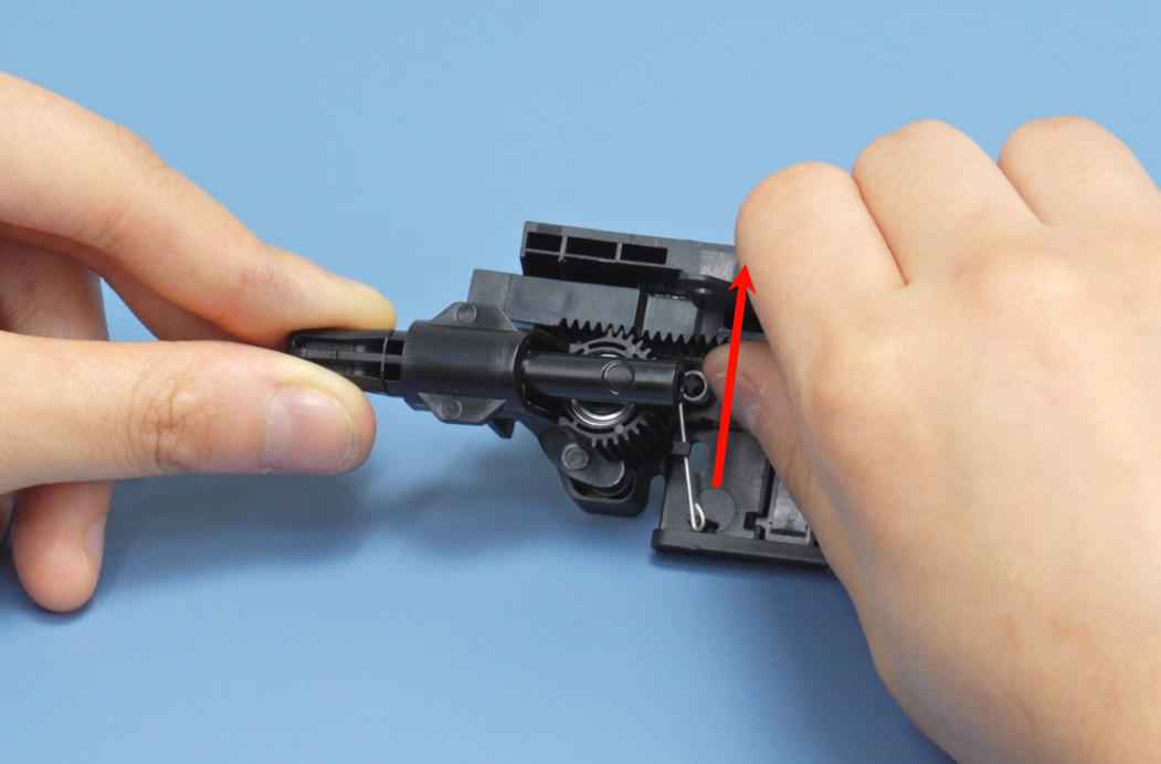
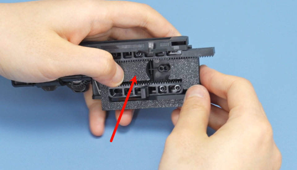
While pressing the rack backwards, maneuver the cutter rod towards the rear of the machine casing.
If the filament cutter stopper block cannot be repaired using this method, it is recommended that you follow the steps below to remove the filament cutter stopper block for repair.
¶ Tools and materials needed
H2.0 hex wrench
Installation Aid for H2D Filament Cutter Stopper(Optional, for H2D printer only)
The H2S cutter stpper repair model will be uploaded to the Makerworld website soon—please stay tuned.
10 minutes
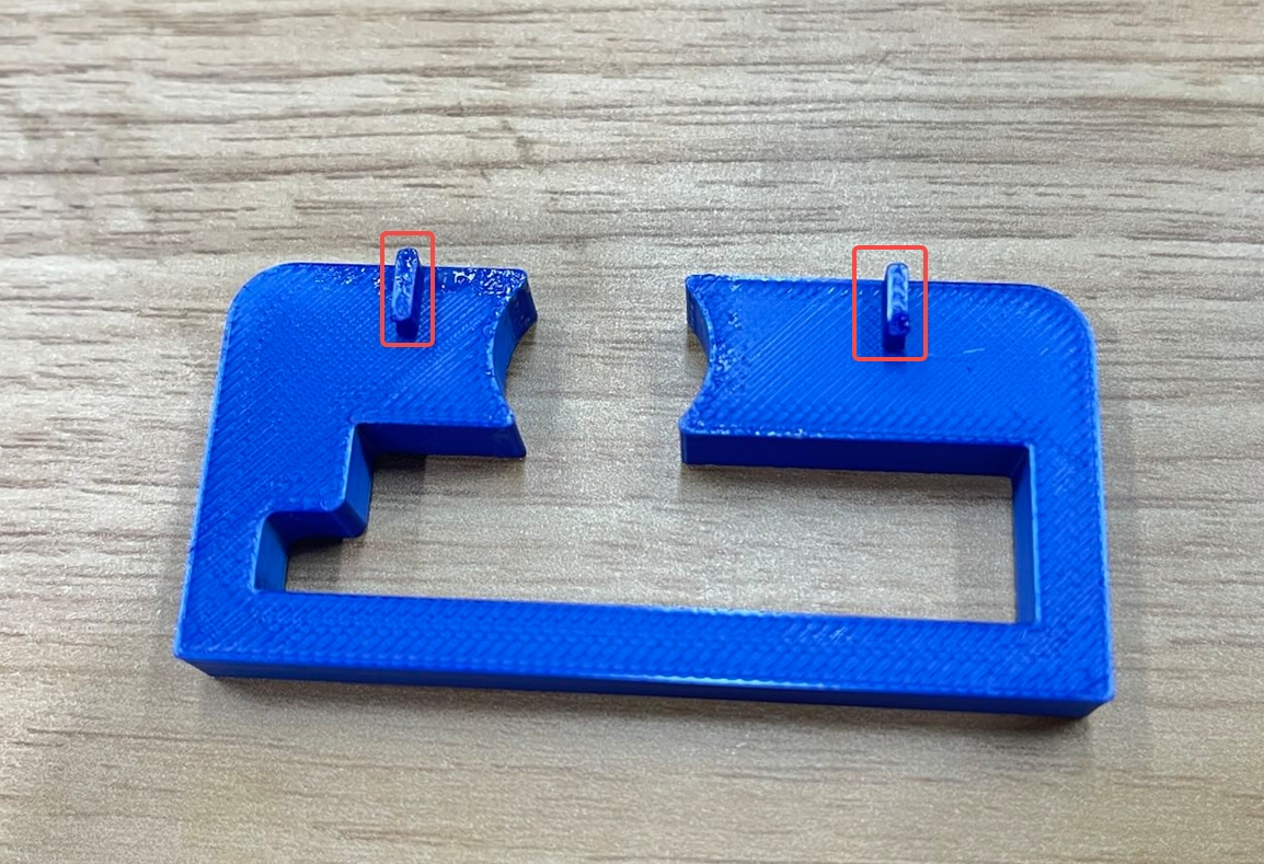
If you need to print an auxiliary tool beforehand, be sure to distinguish between the left and right versions.
¶ Safety Warning
It's crucial to power off the printer before conducting any maintenance work, including work on the printer's electronics and tool head wires. Performing tasks with the printer on can result in a short circuit, leading to electronic damage and safety hazards.
During maintenance or troubleshooting, you may need to disassemble parts, including the hotend. This exposes wires and electrical components that could short circuit if they contact each other, other metal, or electronic components while the printer is still on. This can result in damage to the printer's electronics and additional issues.
Therefore, it's crucial to turn off the printer and disconnect it from the power source before conducting any maintenance. This prevents short circuits or damage to the printer's electronics, ensuring safe and effective maintenance. For any concerns or questions about following this guide, open a new ticket in our Support Page and we will do our best to respond promptly and provide the assistance you need.
¶ Video Guide
The circular gear screw installation shown in the video applies only to H2D. For H2S, please follow the instructions in the upcoming step-by-step guide.
¶ Operation Guide
¶ Remove the Filament Cutter Stopper
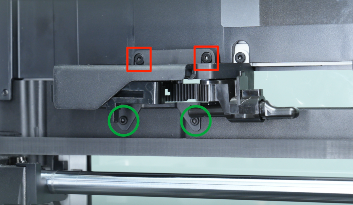
Use an H2.0 hex wrench to remove the four fixing screws. The red screws are BT2.6*8, and the green screws are M2.5*5.
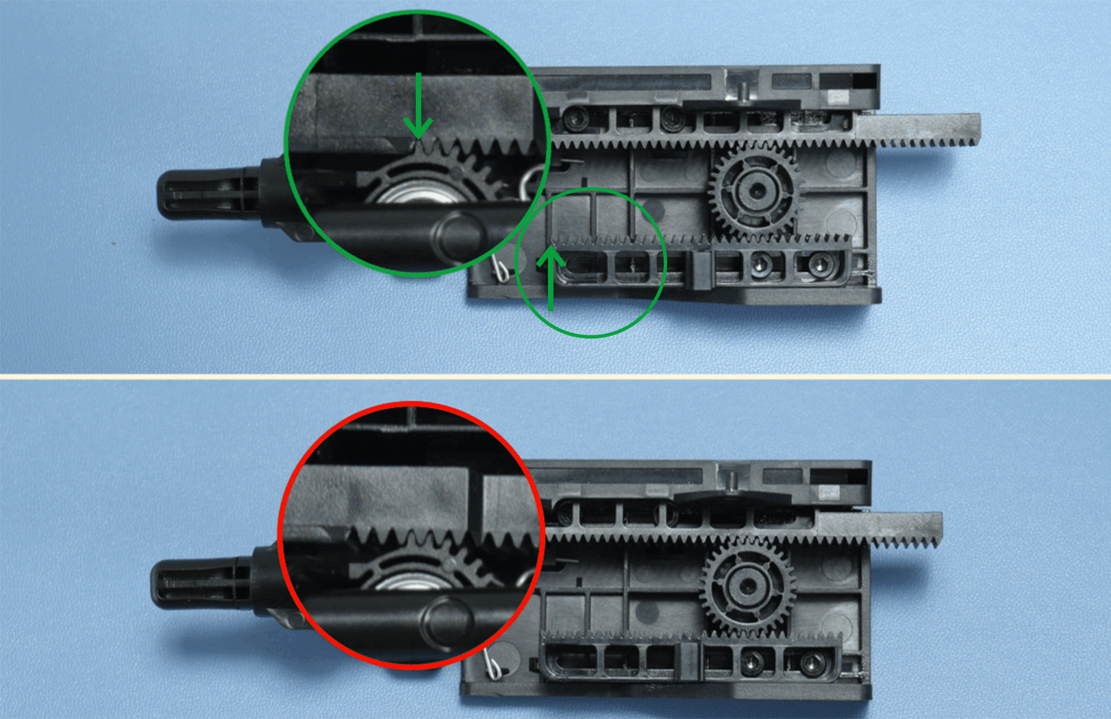
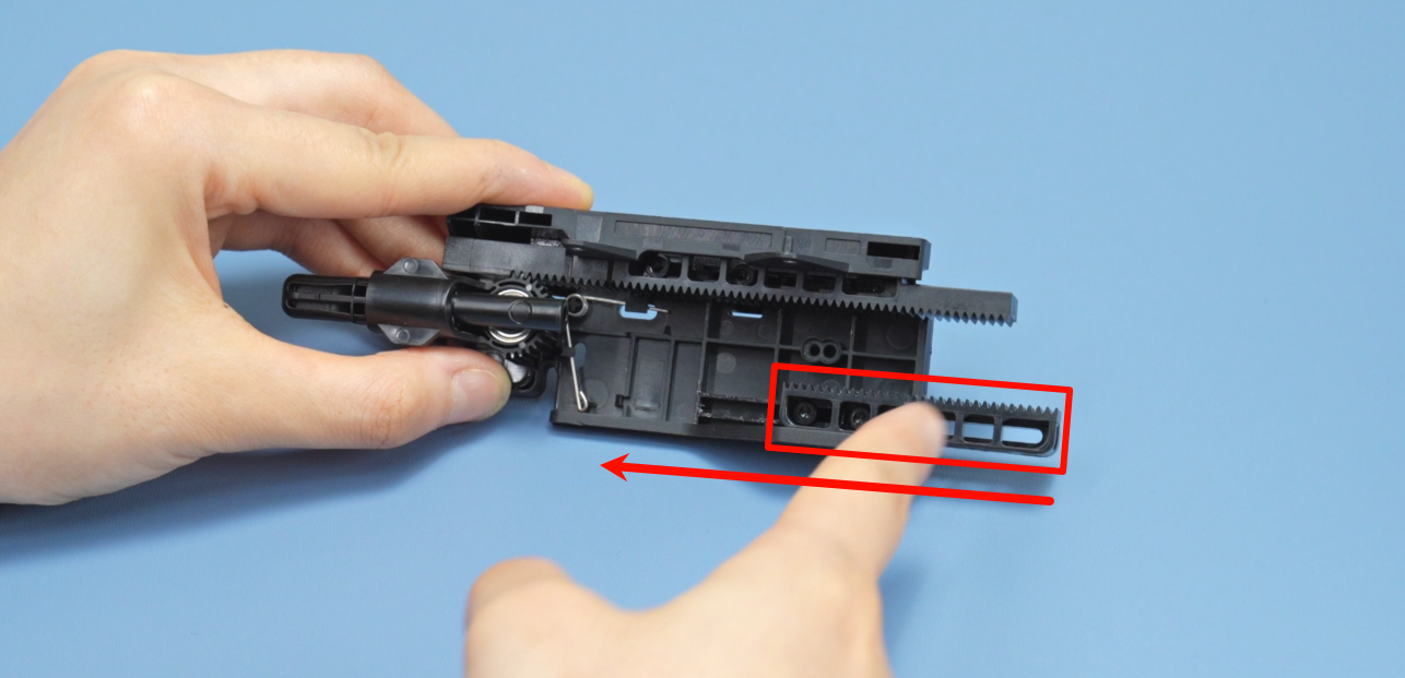
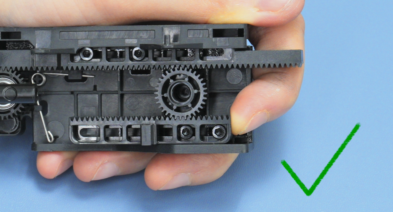
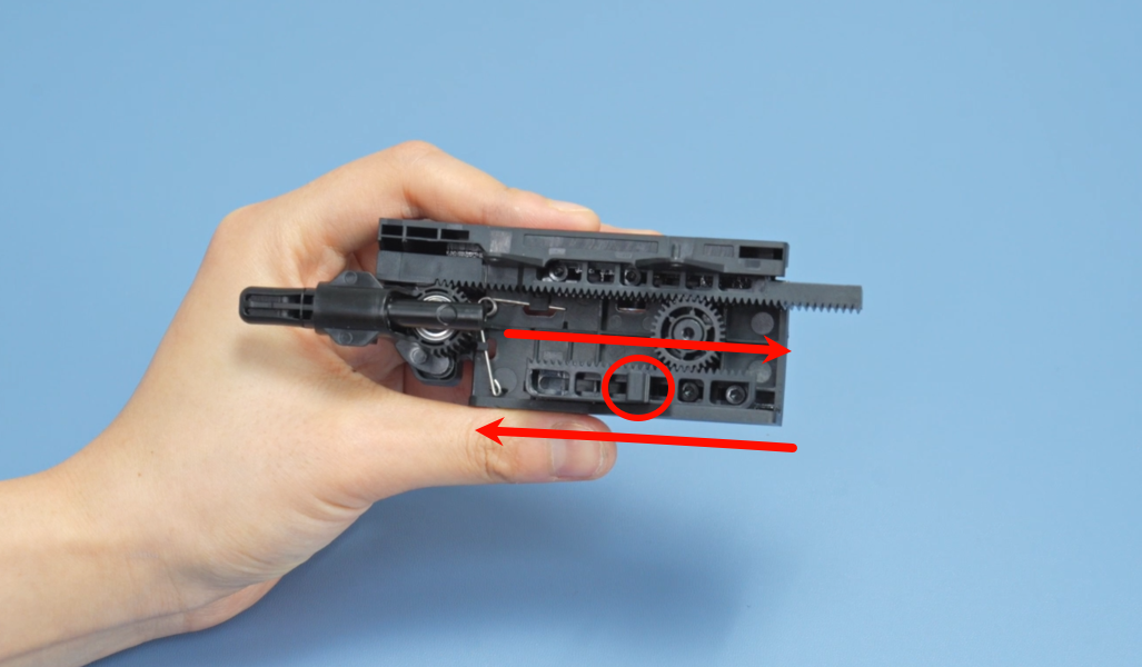
The green area shows the correct position of the upper and lower racks, while the red area indicates that the gear position needs to be readjusted.
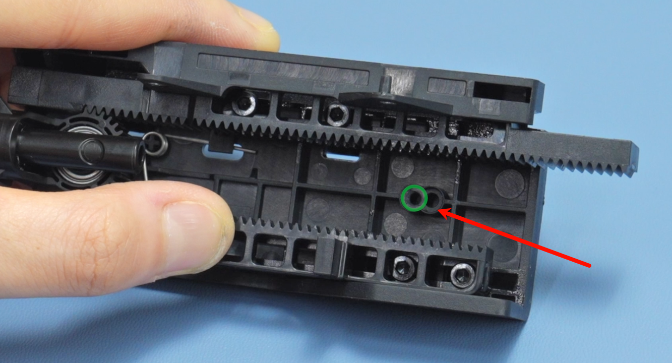
¶ Adjust the Gear Position(Gear Installation Hole Alignment: H2D Left vs H2S Right):
H2D: align the gear with the left-side hole.
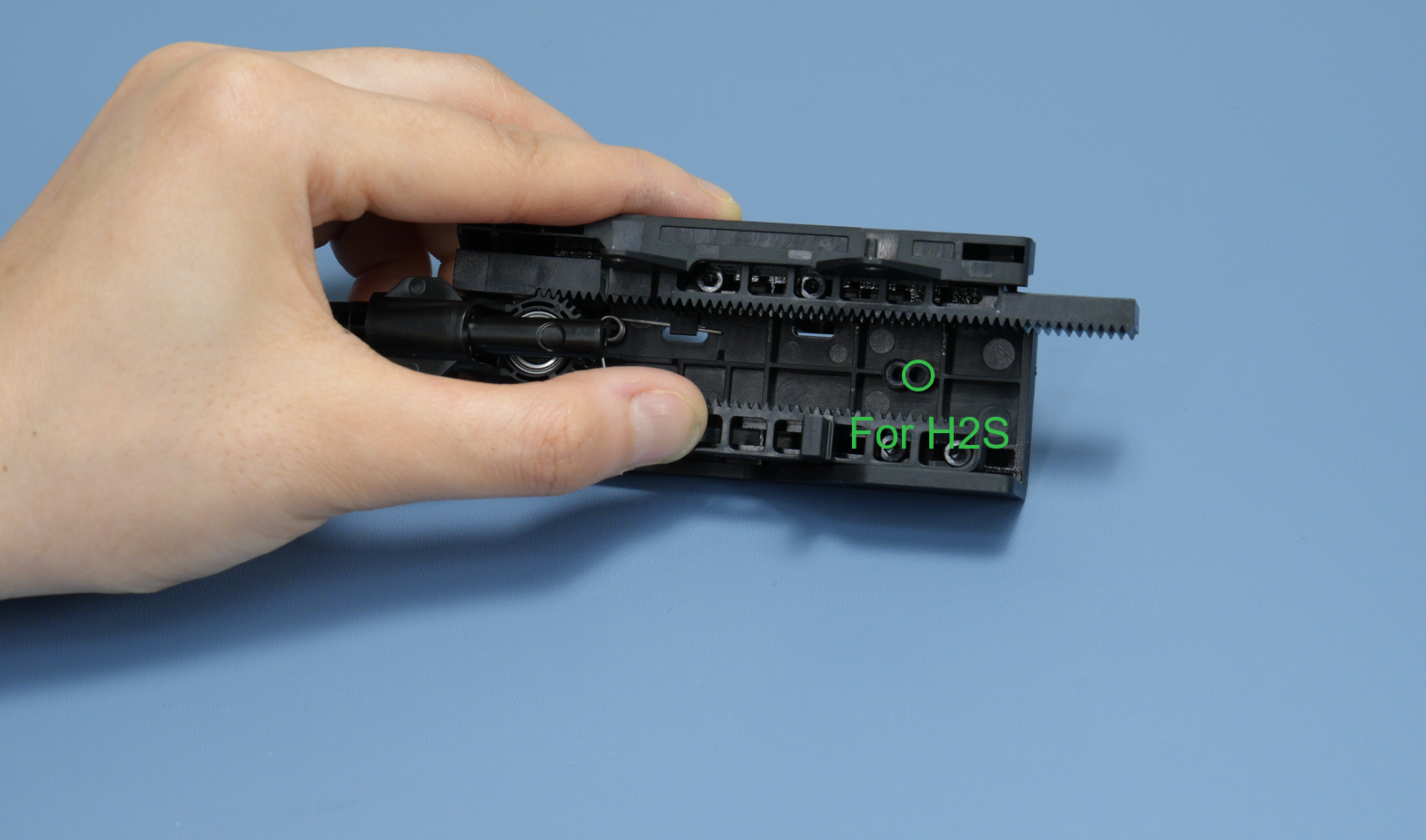
H2S: align the gear with the right-side hole.
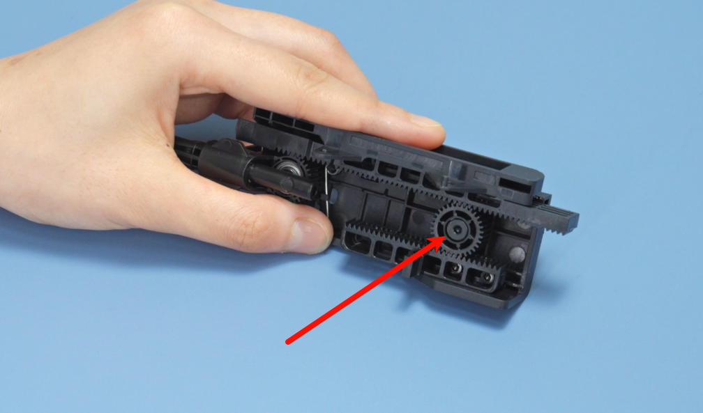
Use an H2.0 hex wrench to remove the fixing screw of the gear on the right side, and then take out the gear.
 |
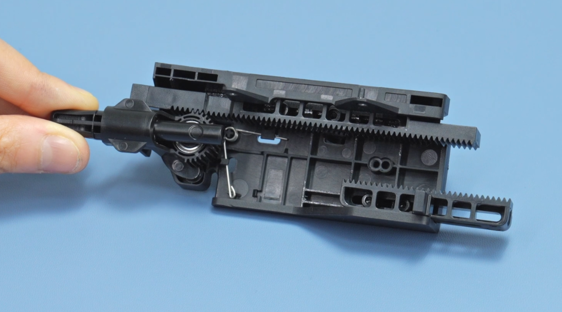 |
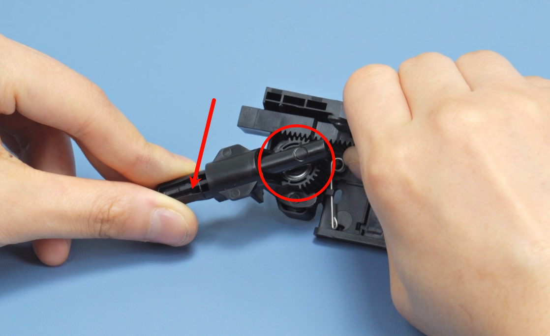
Next, press the rack downward while rotating the filament cutter stopper assembly downward.
 |
 |
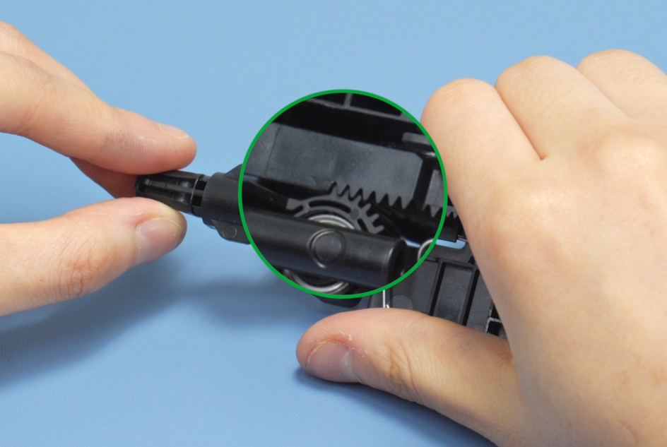
The diagram below shows the correct alignment state of the gears.
After adjusting the gears, push the bottom rack all the way to the left and keep it fixed. Then, install the gears and tighten the screws to secure them.
¶ H2D circular gear screw installation requirement: align the gear with the left-side hole.
¶ H2S circular gear screw installation requirement: align the gear with the right-side hole.
If you have a printing installation aid, you can insert the fixture into the filament cutter stopper to assist with the installation of the gears and screws. Make sure that once the assistive model is correctly inserted, the left and right positioning bumps lock it in place, with no movement on either side.
H2D Installation Aid for Filament Cutter Stopper(For H2D Only)
H2S Installation Aid for Filament Cutter Stopper(For H2S Only)
After installation, move the bottom rack to check if the swing rod returns to its original position and moves smoothly.
If the rack movement is stuck or sluggish, use an H2.0 hex wrench to slightly loosen the two screws corresponding to the rack—specifically, the two fixing screws for the top rack and the two for the bottom rack.
Before installing the filament cutter stopper, move the X-axis to the front (close to the front glass door).
¶ End Notes
We hope the detailed guide provided has been helpful and informative.
If this guide does not solve your problem, please submit a technical ticket, we will answer your questions and provide assistance.
If you have any suggestions or feedback on this Wiki, please leave a message in the comment area. Thank you for your support and attention!