¶ Issue Description
The filter switch flap hall sensor detects whether the filter switch flap has moved to its target position. This HMS error occurs when:
-
The Hall sensor is damaged/defective
-
Its wiring harness is loose or detached
¶ Troubleshooting
¶ Tools, Equipment and Materials
-
H2.0 Allen key
-
H1.5 Allen key
-
Multimeter (optional)
¶ Fault Isolation Process
-
Check if the filter switch flap hall sensor cable is loose/disconnected.
-
If cable is intact, the Hall sensor itself may be damaged or experiencing power supply issues.
¶ Solutions
Users may adjust the order of these solutions as needed.
-
Check if the filter switch flap Hall sensor cable is loose or detached
-
Check if the connector on the Hall sensor end of the cable is loose or detached
-
Check if the connector on the MC module end of the cable is loose or detached
-
-
Check if the Hall sensor power supply is normal
Measure the Hall sensor voltage and check if the power supply voltage is normal 3.3v
-
Check if the Hall sensor itself is damaged
Observe whether the Hall sensor has structural damage, mildew, rust, or component detachment
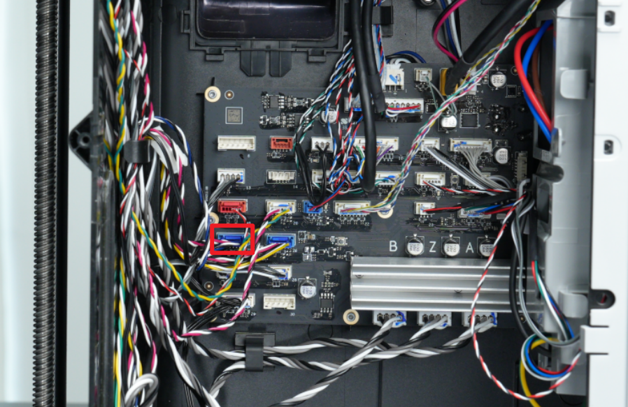
Step 1: Check if the filter switch flap Hall sensor connector is loose
You can first refer to this Wiki to remove the printer rear panel and purge chute:
Then you can refer to the following figure to check if the Hall connector is normal. If the connector is loose, it is recommended to plug it in and try again to check if it can be restored to normal:
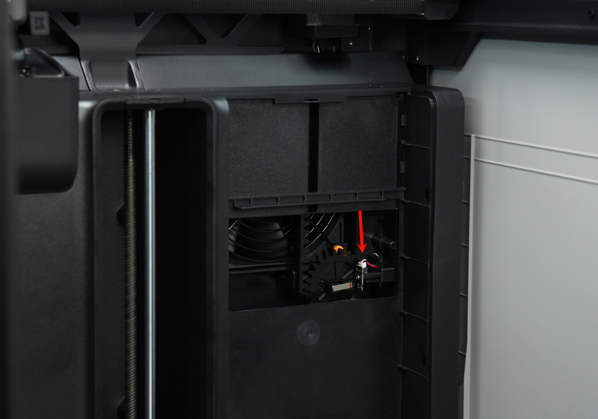
Step 2: Check if the Hall sensor is damaged
Check if the Hall sensor has structural damage, mildew, rust, or component detachment.
If the Hall sensor is abnormal, you need to replace the right inner lining cover. You can refer to this Wiki to replace the right inner lining cover.
Repalce Right Inner Lining/Chamber Heater Unit/Chamber Heat Circulation Fan
Step 3: Check if the voltage of the Hall sensor is normal
Pull out the Hall sensor cable, which has three colors:
-
Black;
-
Color;
-
White
It is recommended to use a multimeter to detect the voltage of the Hall effect sensor. Make a judgment based on the measurement results and refer to the following instructions:
Disconnect the cable from one side of the Hall effect sensor and measure the voltage between the red and black wires. Under normal circumstances, the voltage between the red and black wires is 3.3v.
-
If the voltage is not 3.3v, it may be that the cable is abnormal or the MC board is abnormal. At this time, you can disconnect the Hall connector from the MC board, measure the interface voltage on the MC board, and check whether the voltage is normal. If the voltage is abnormal, it is the MC board that is abnormal;
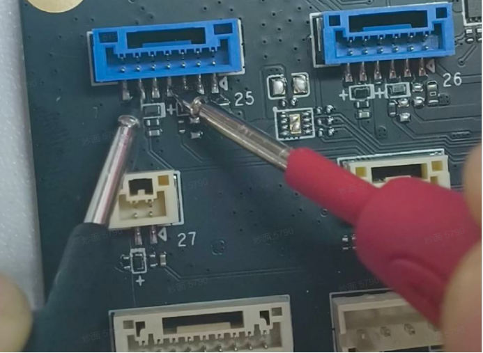
-
If the voltage is normal. Connect the Hall connector to the Hall effect board and measure the voltage between white and black. While measuring, use magnets with different magnetic poles close to the Hall effect board to check whether the voltage changes. If there is no change, the Hall effect board may be damaged.
-
If the above voltages are normal, we recommend that you power off and restart. If the error still occurs after restarting, you can submit a ticket and upload the log.
¶ Equivalent Codes
The following HMS codes represent the same type of issue.
| HMS Code | Description |
|---|---|
| 0300-C200-0001-0002 | Hall sensor of Filter Switch Flap malfunction: please check if the wiring is loose. |
¶ End Notes
We hope the detailed guide provided has been helpful and informative.
If this guide does not solve your problem, please submit a technical ticket, will answer your questions and provide assistance.
If you have any suggestions or feedback on this Wiki, please leave a message in the comment area. Thank you for your support and attention!