¶ Fault Description:
The air vent is controlled by an electromagnet, which opens or closes the vent by reversing the current direction. A built-in Hall sensor continuously monitors the vent’s position. When AMS HT or AMS 2 Pro sends an open/close command but the sensor fails to detect that the vent has reached its expected position, the system will trigger a fault notification.
- Impact:
-
The air vent cannot open or close properly
-
Airflow circulation within AMS may be compromised
-
Heating and moisture removal during drying may be affected
-
The sealing effect may be reduced when the system is not in drying mode
¶ Safety Warning
It's crucial to power off the printer before conducting any maintenance work, including work on the printer's electronics and tool head wires. Performing tasks with the printer on can result in a short circuit, leading to electronic damage and safety hazards.
During maintenance or troubleshooting, you may need to disassemble parts, including the hotend. This exposes wires and electrical components that could short circuit if they contact each other, other metal, or electronic components while the printer is still on. This can result in damage to the printer's electronics and additional issues.
Therefore, it's crucial to turn off the printer and disconnect it from the power source before conducting any maintenance. This prevents short circuits or damage to the printer's electronics, ensuring safe and effective maintenance. For any concerns or questions about following this guide, open a new ticket in our Support Page and we will do our best to respond promptly and provide the assistance you need.
¶ AMS 2 Pro
¶ Replug the Vent Cable
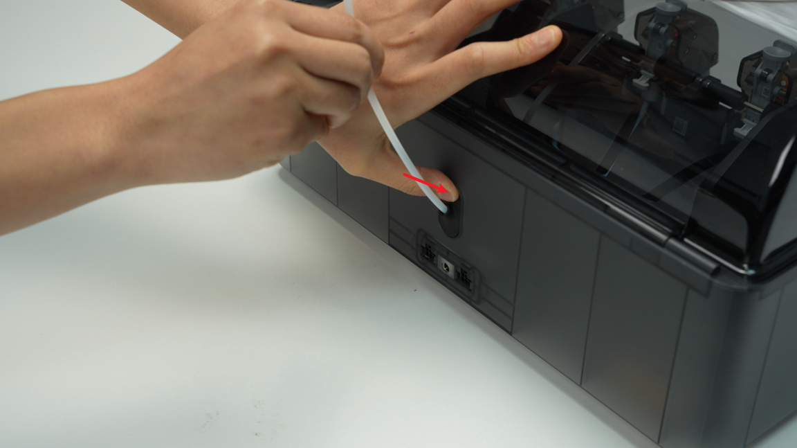
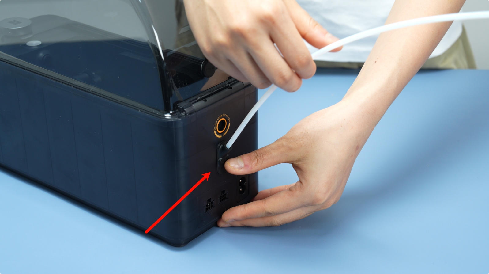
¶ Step 1 – Remove the PTFE Tube on the Back of the AMS 2 Pro
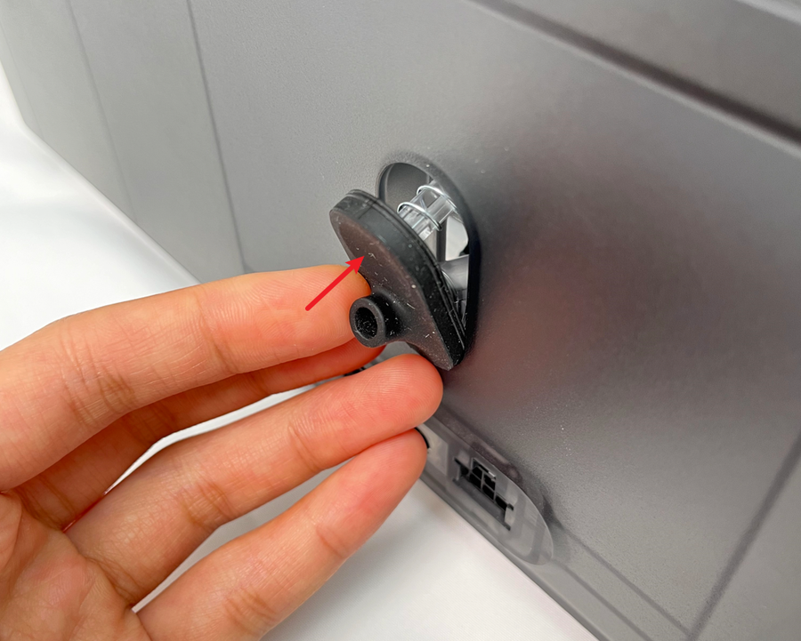
Press the PTFE tube release button on the back of the AMS to unlock the fitting, then pull out the PTFE tube.
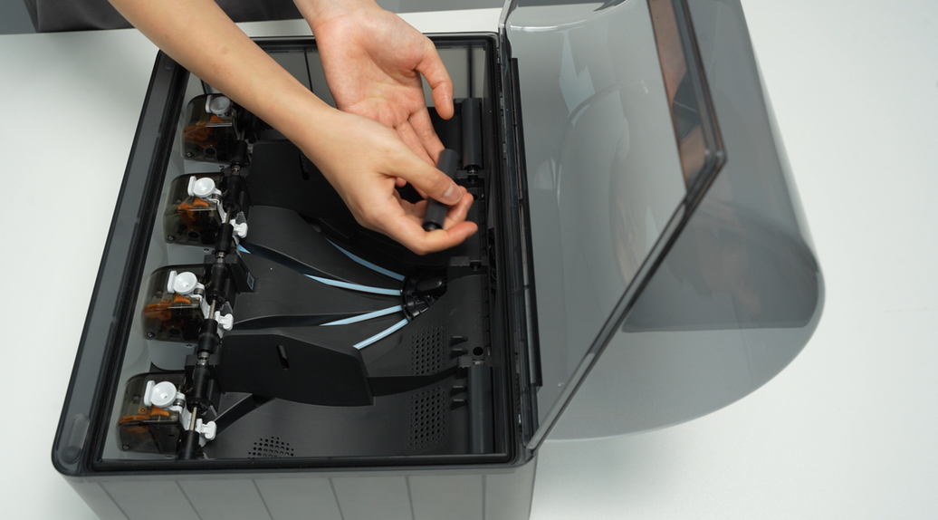
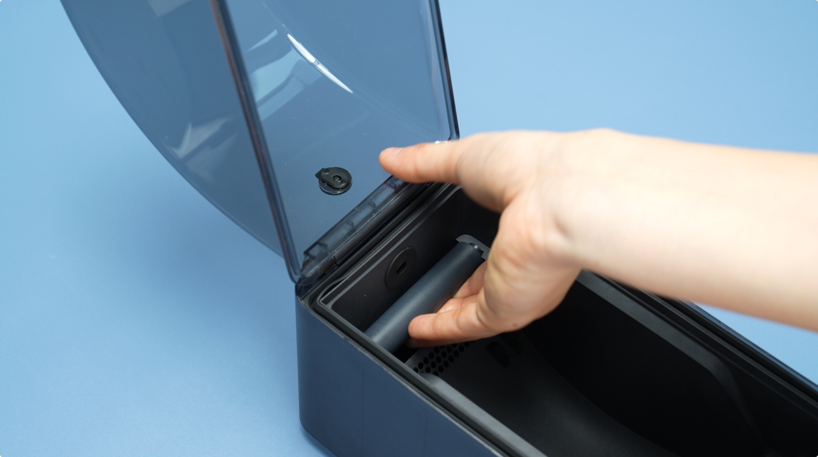
¶ Step 2 - Pull out the PTFE Tube Release Button
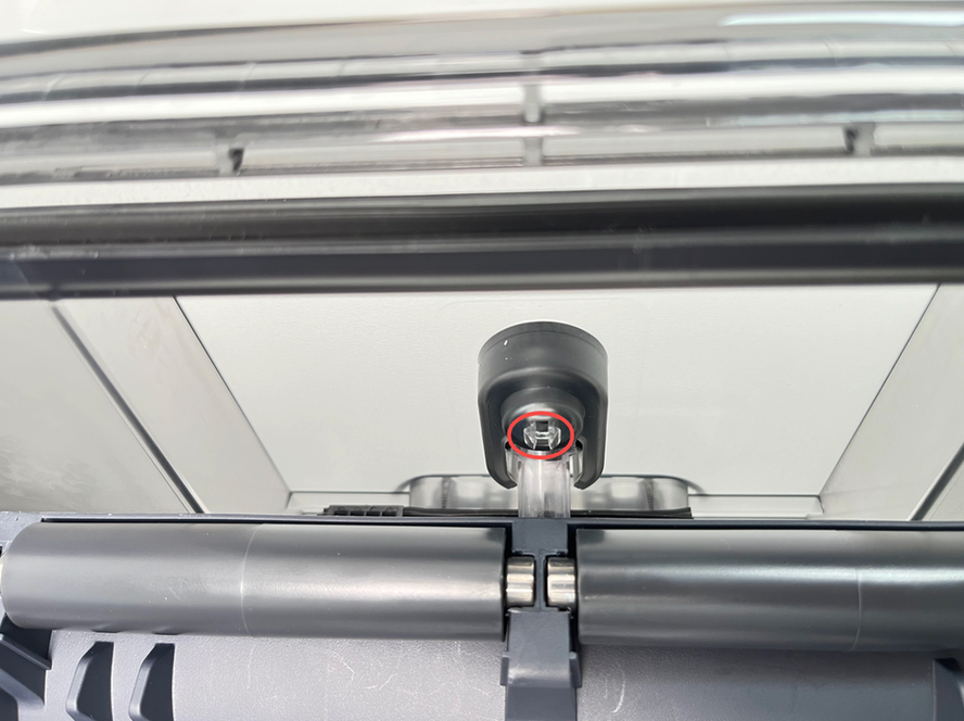
Pinch the clip from the inside of the lower cover to automatically pop open the PTFE tube release button, and then pull out the PTFE tube release button from the back of the AMS 2 Pro.
When squeezing the buckle, use your other hand to support the PTFE tube release button from the back of the AMS 2 Pro to prevent the spring from popping out and getting lost.
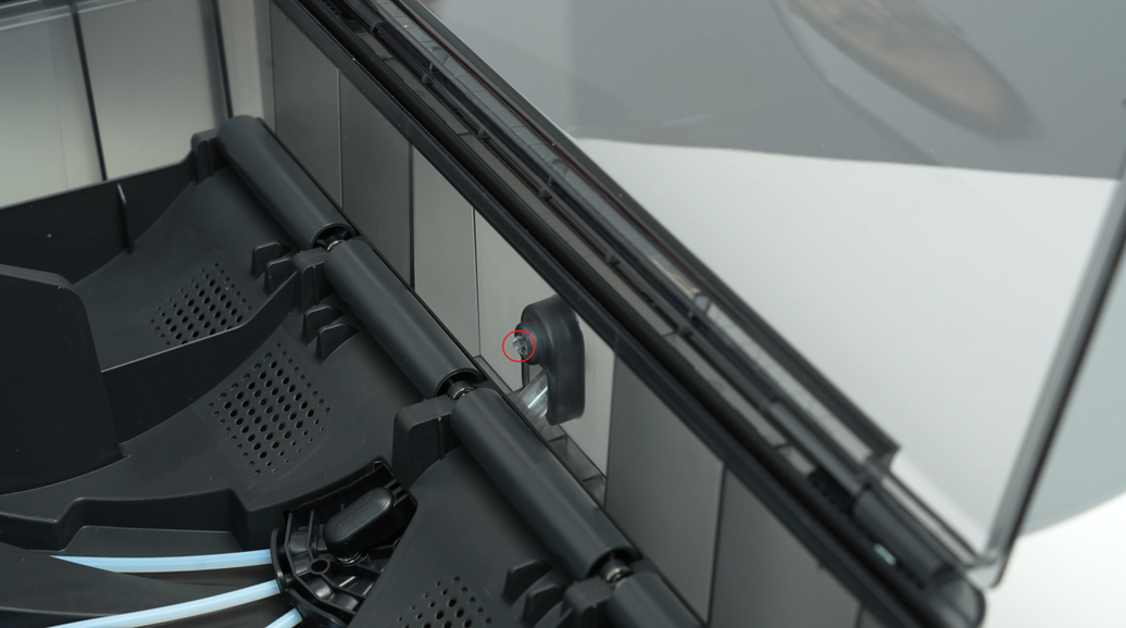
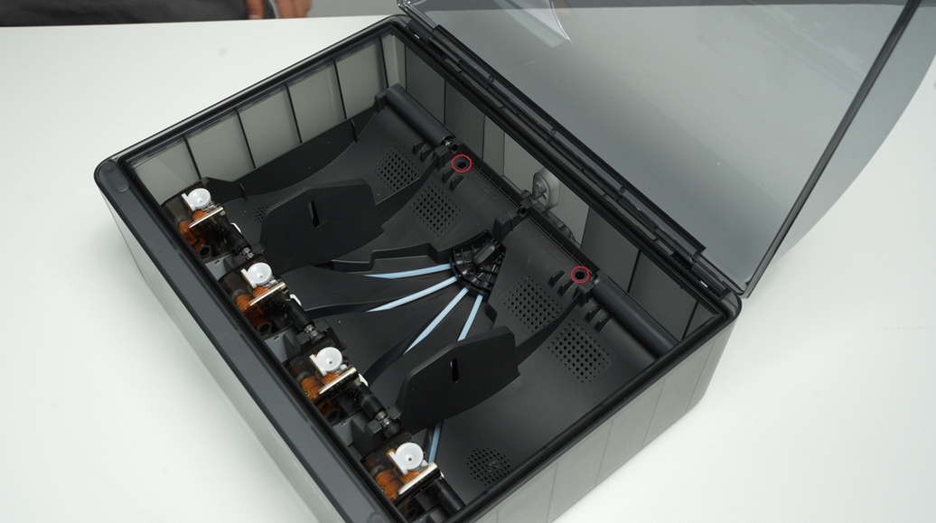
¶ Step 3 – Remove the AMS 2 Pro Main Frame Assembly
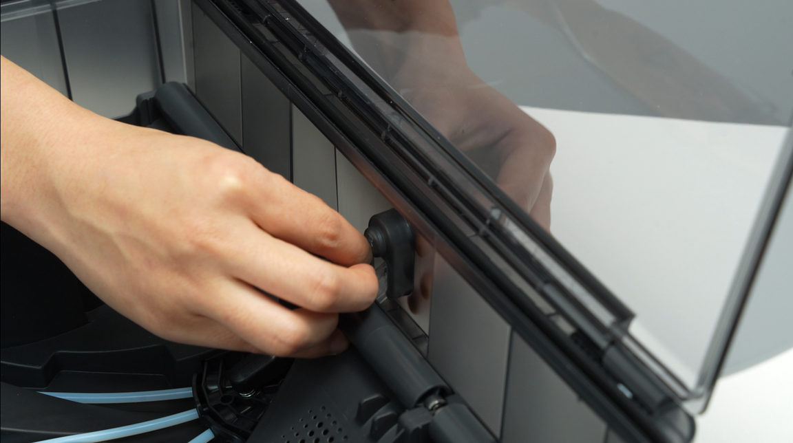
Remove the driven support sleeve assembly of the two middle slots to expose the two screw holes. When removing the bearing sleeve, be careful with the bearings at both ends to avoid losing them.
Remove the two screws A that secure the AMS 2 Pro main frame.
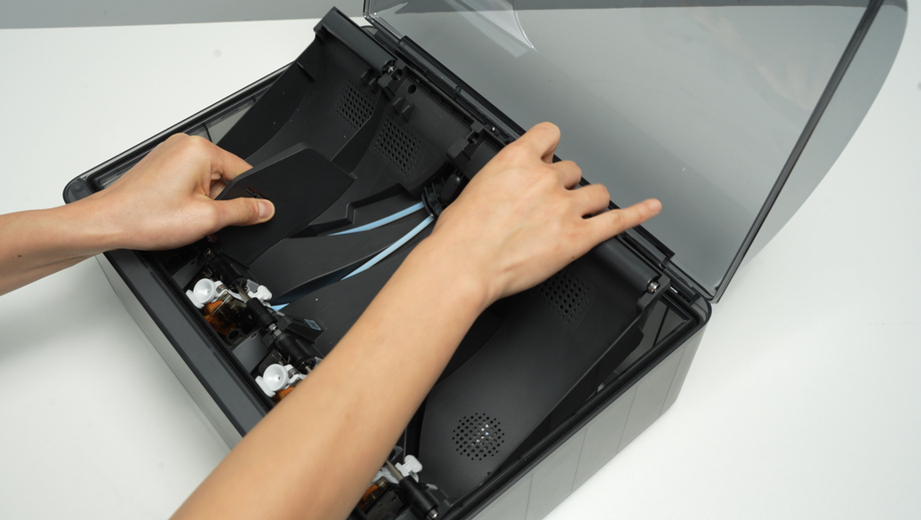
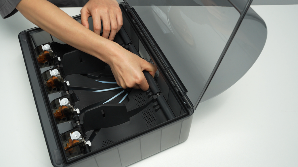
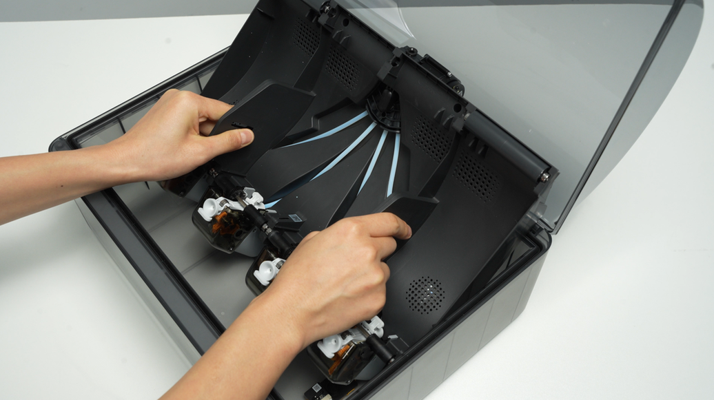
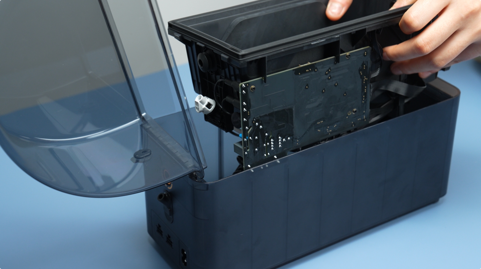
Lift the rear part of the main frame completely and place it vertically on the lower cover of the AMS 2 Pro. Note that there are cables connected, so avoid operating violently. When lifting, it is recommended to lift the front part of the main frame first, and then push it forward to make room for the rear part of the frame.
When placing the AMS 2 Pro main frame vertically, avoid the electronic components of the vent to prevent them from being crushed.
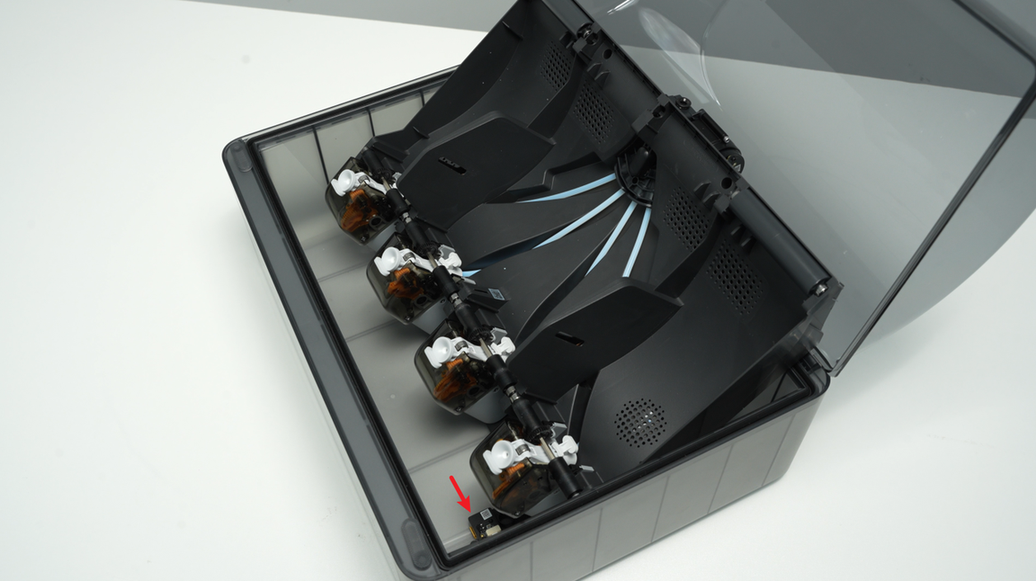
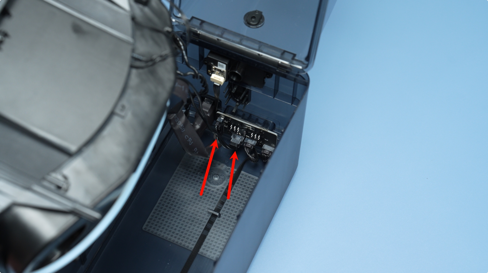
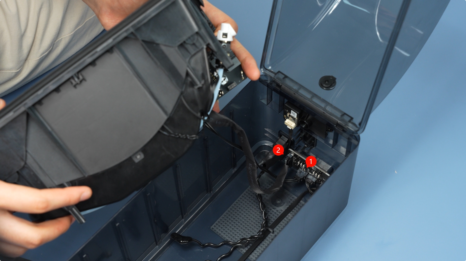
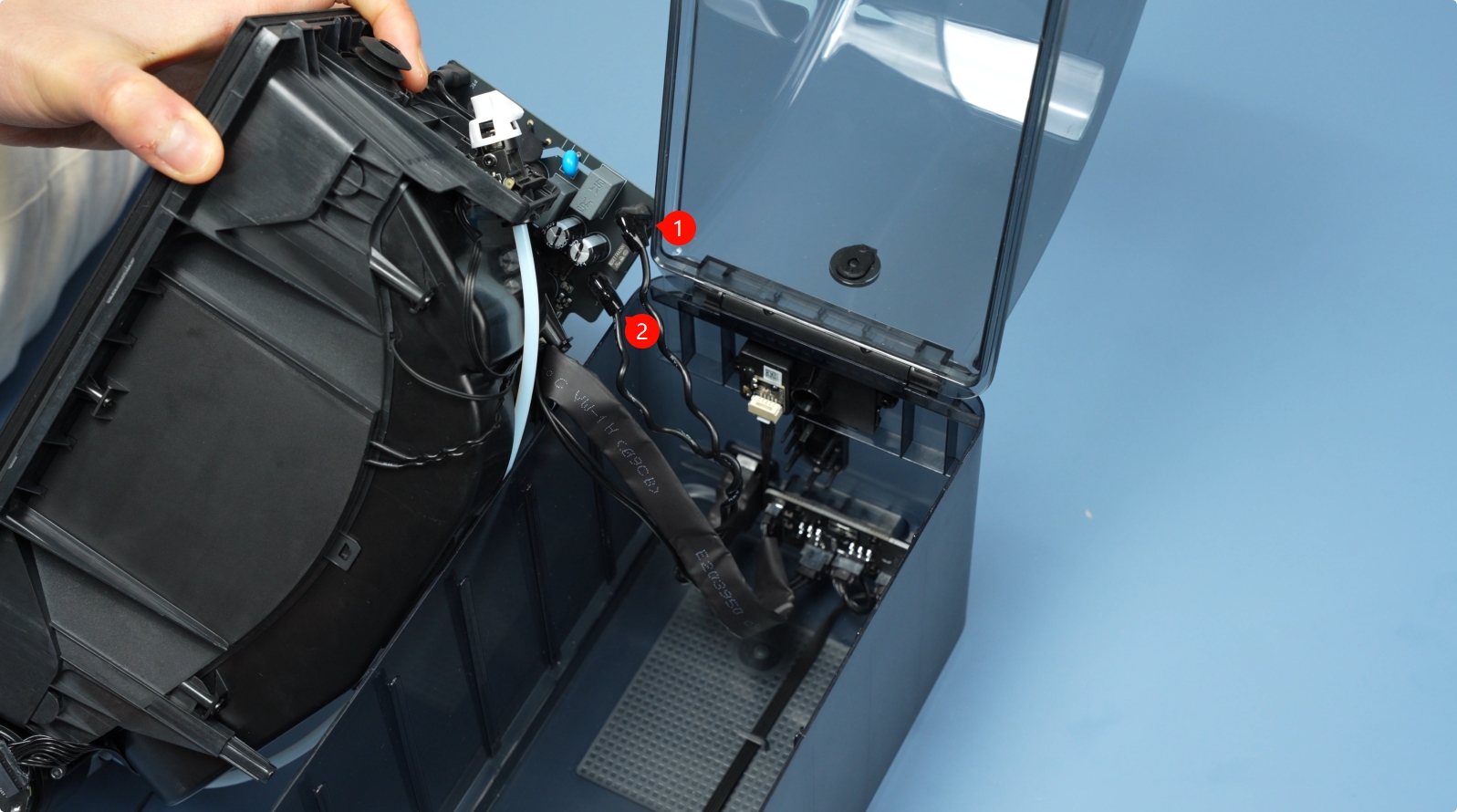
Unlock the plug buckle, unplug the signal cable and power cable on the AMS 2 Pro power board, and lift out the AMS 2 Pro main frame assembly as a whole.

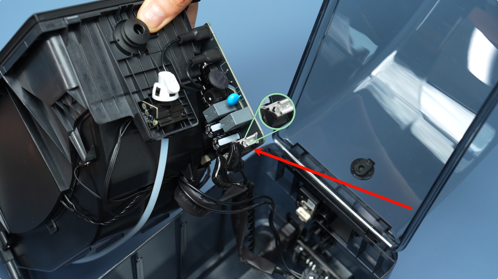
¶ Step 4 – Reseat the Vent Cable
The intake vent is located on the side wall; the exhaust vent is on the bottom. Reseat the connector on the applicable vent based on your issue.

If the issue persists after reseating the cable, proceed to replace the vent assembly.
Considering that cables rarely fail, start by replacing the vent itself when replacing the vent assembly. Only replace the cable if the problem persists.
¶ Replace the Vent Assembly
¶ Step 1 - Install the AMS 2 Pro air intake or air vent
After aligning the screw holes, push in the direction of the screw holes to press the vent to the corresponding hole, tighten the 2 screws B or C of the vent, and plug the vent back in.
When installing, pay attention to the direction of the vent. If the installation direction is wrong, the vent cannot be stuck in place. Do not press it down violently. The opening direction of the socket of the air intake faces upward, and the opening direction of the socket of the air vent faces right.

¶ Step 2 - Install the main frame assembly and driven support sleeve assembly
Install the AMS 2 Pro main frame assembly into the lower cover and connect the signal cable and power cable to the AMS 2 Pro power board.
Align the tabs of the bottom cover unit with the slots of the middle frame, and then insert and install.

After the AMS 2 Pro main frame is installed in place, tighten the two screws to secure it.
Install the two middle driven support sleeve assemblies, making sure that the bearings on both ends of all support shafts are pressed into place.
¶ Step 3 - Install the PTFE tube release button
Press the PTFE tube release button back into the housing in the following direction, insert the buckle into the corresponding slot smoothly, and keep the black silicone housing embedded flat.
¶ Step 4 - Connect the PTFE tube
Check to make sure that the PTFE tube silicone bracket is aligned with the filament hole of the filament hub unit, and push the PTFE tube from the rear of the AMS 2 Pro. After installation, pull the PTFE tube to confirm that the PTFE tube is fixed.
¶ AMS HT
¶ Replug the Vent Cable
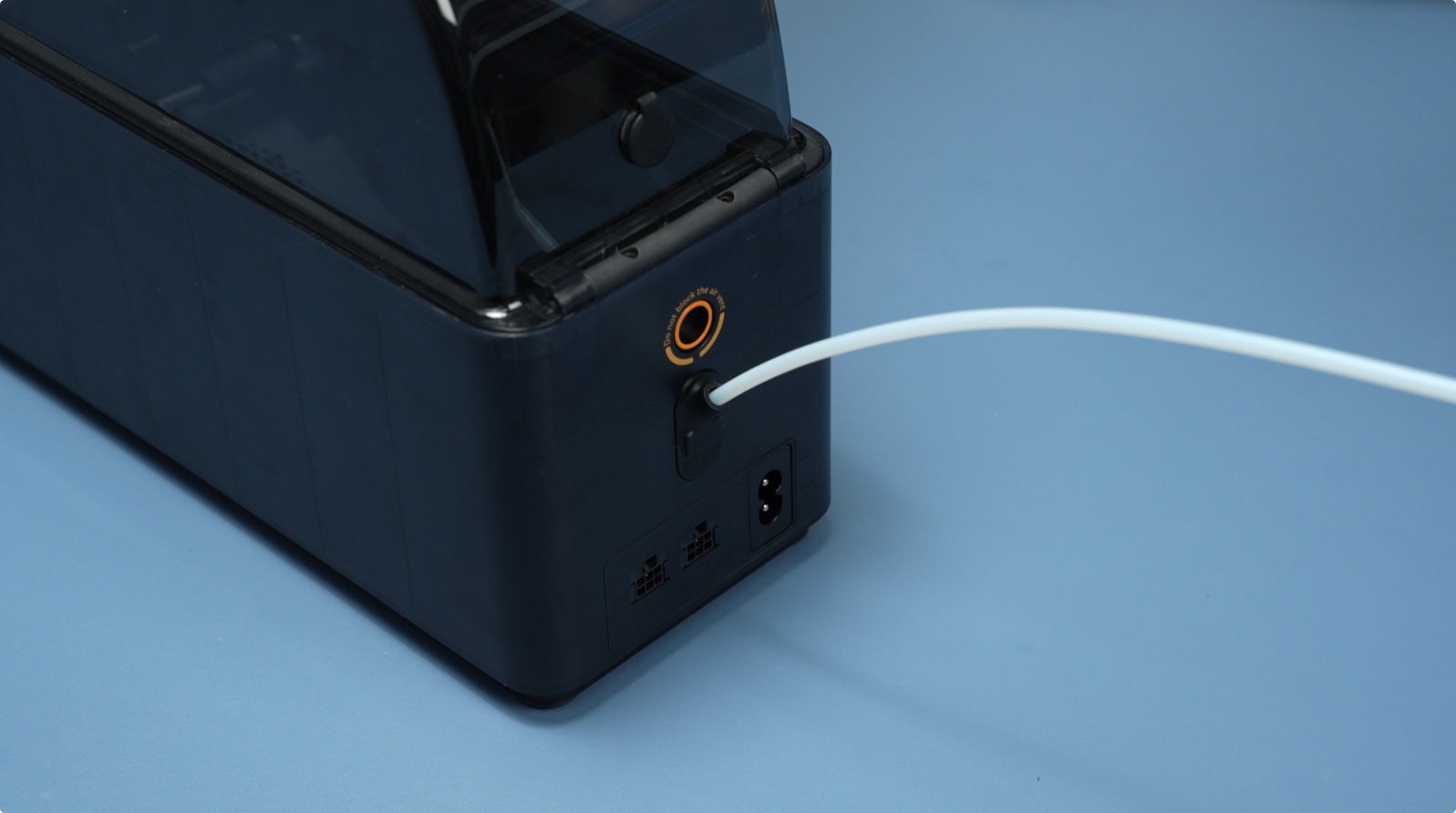
¶ Step 1 - Remove the PTFE Tube from AMS HT Back
Press the PTFE tube release button on the back of the AMS HT to unlock the connector, then pull out the PTFE tube.
¶ Step 2 - Remove the AMS HT Main Frame
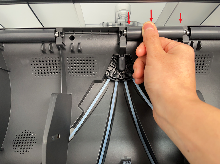
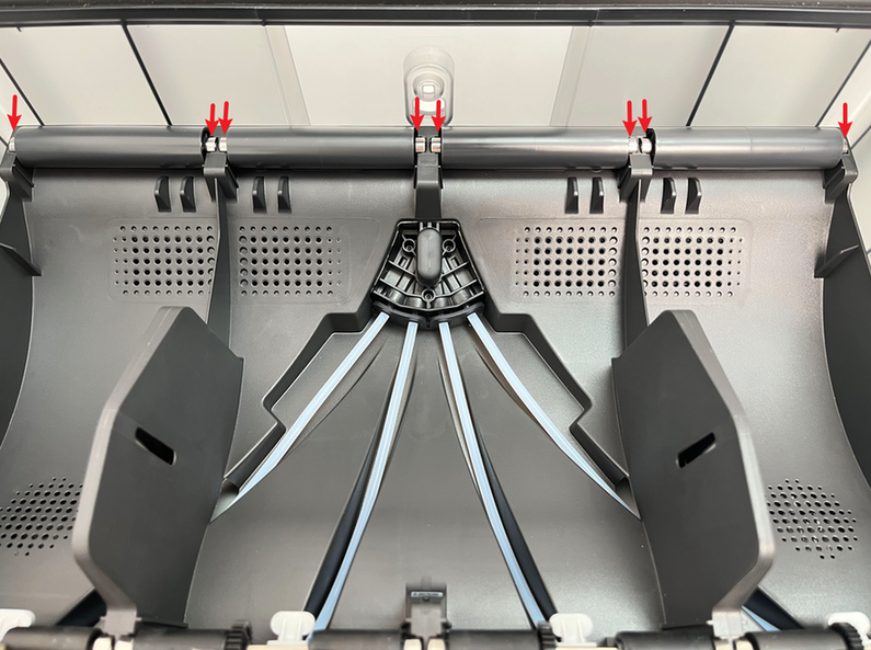
First, remove the Driven Support Shaft and Active Support Shaft from the material slot. Be careful with the bearings at both ends when removing the bearing sleeves.
 |
 |
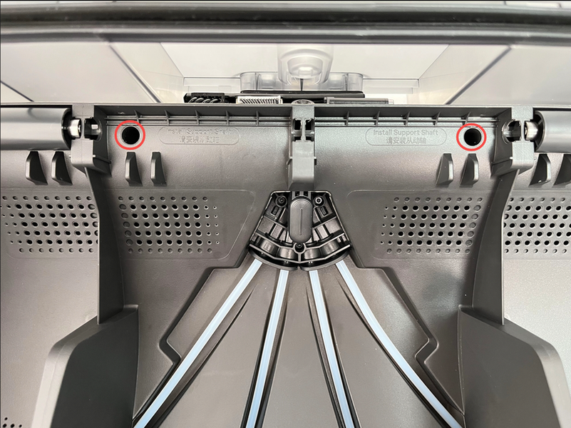
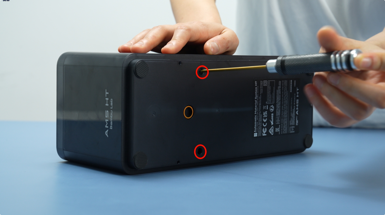
Remove the two bottom screws (BT3×8).
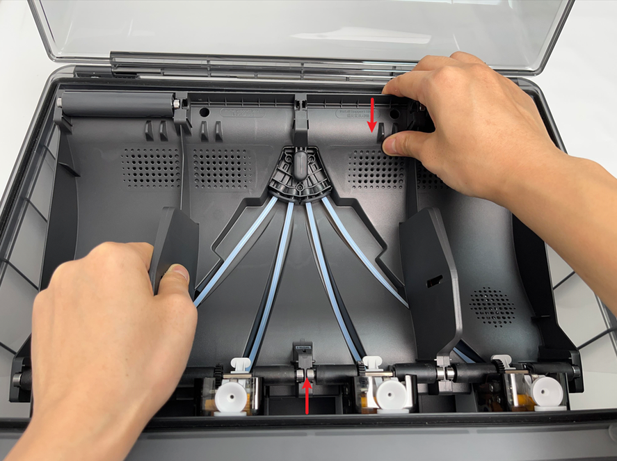
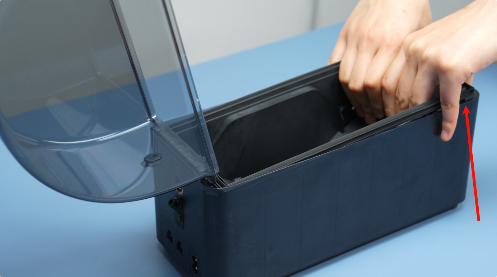
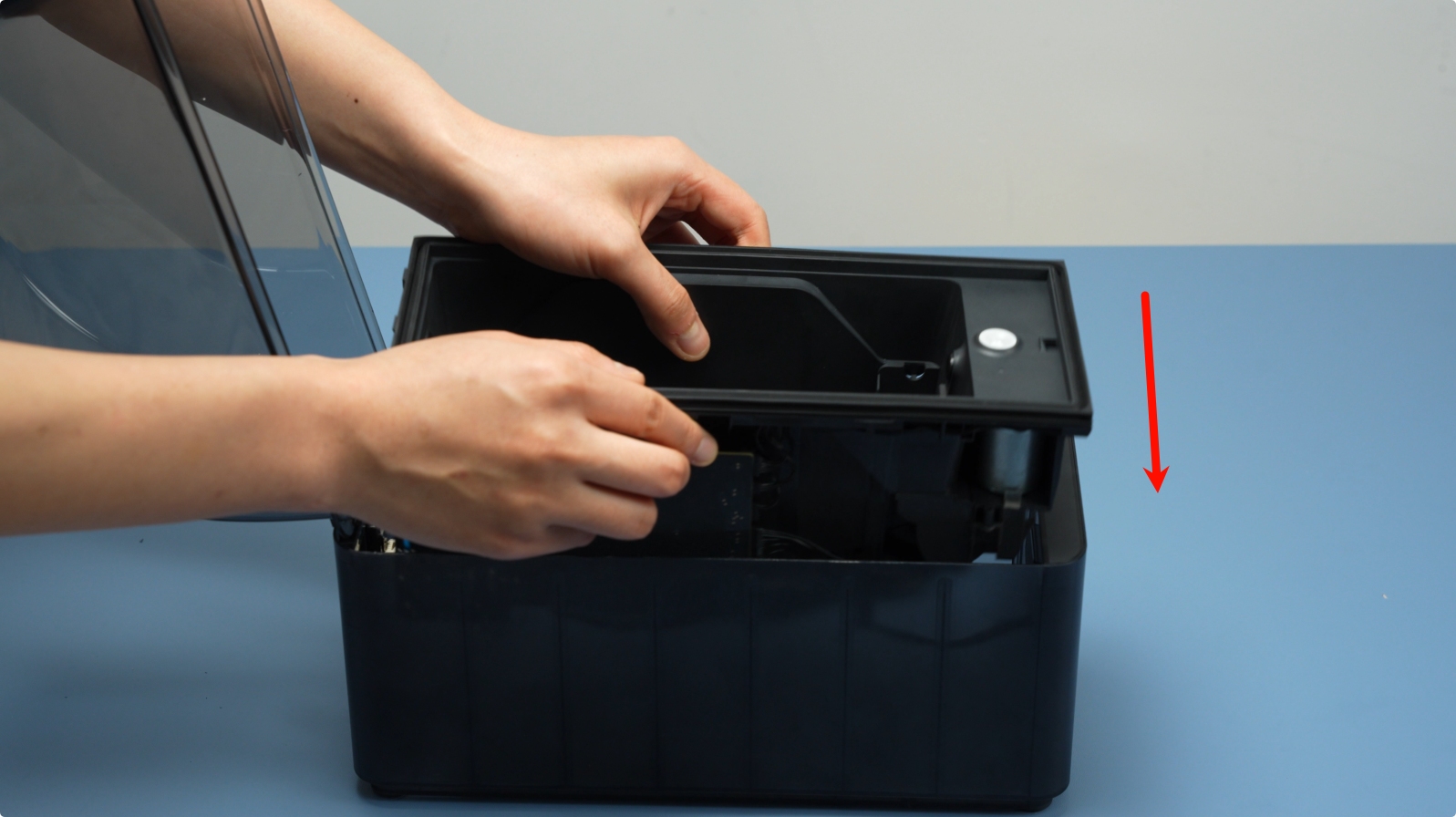
Lift the main frame assembly slowly upward.
 |
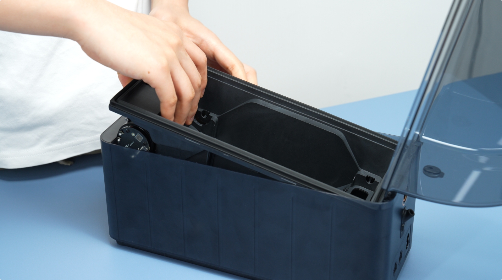 |
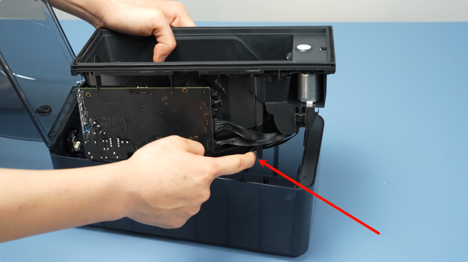
After opening the gap, lift the main frame assembly. Note: Cables are connected—avoid forceful operation.
Unlock the connector latch and disconnect the front screen cable.

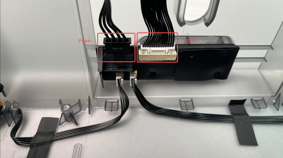
Next, disconnect the signal and power cables from the AMS HT Power Board.
 |
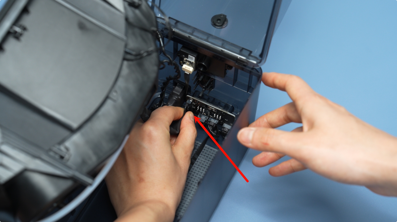 |
Remove the power socket-to-mainboard cable. Press the unlock latch and pull out the connector, and lift out the AMS HT main frame assembly as a whole.
 |
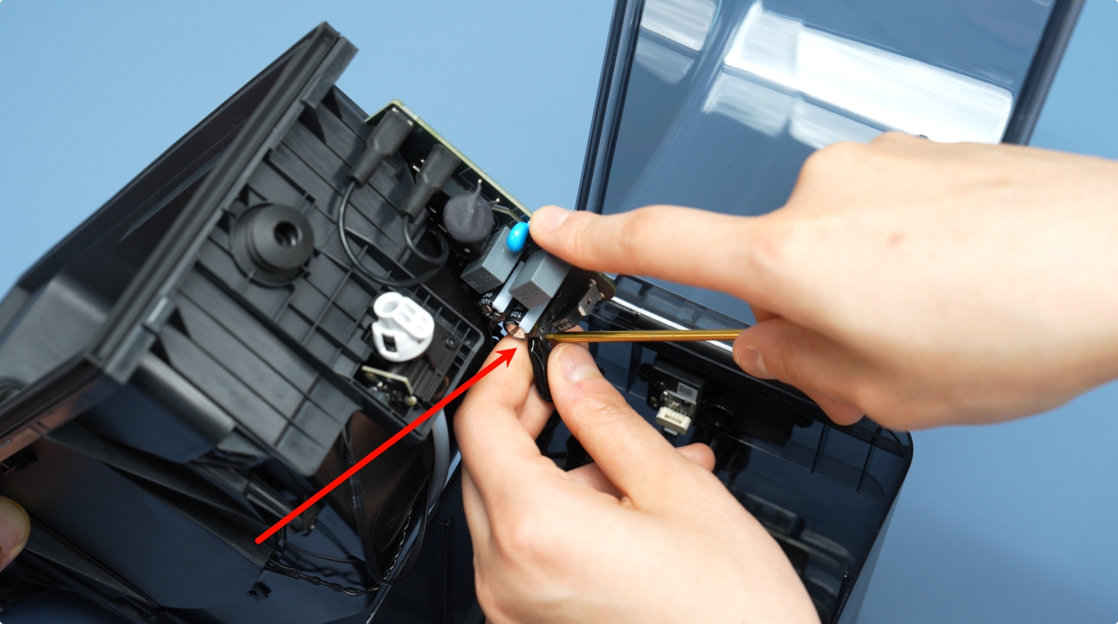 |
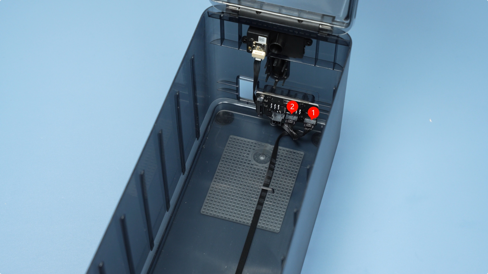
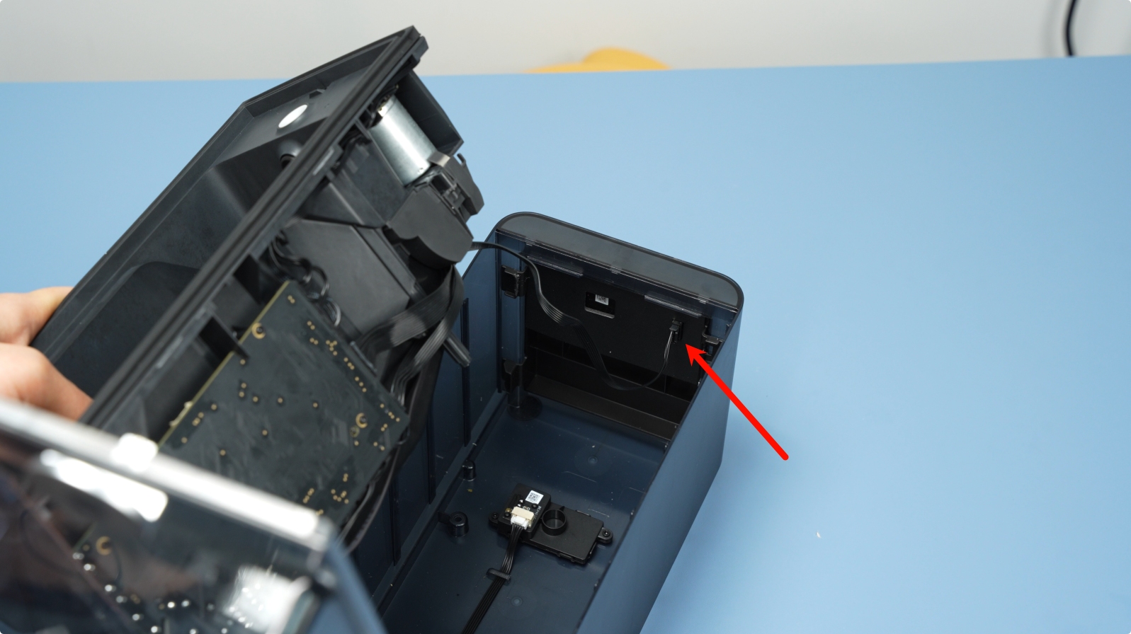
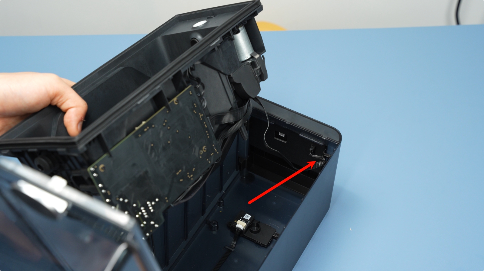
¶ Step 3 – Reseat the Air Vent Cables
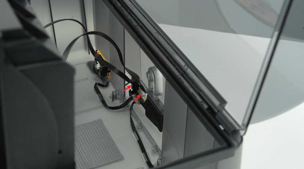
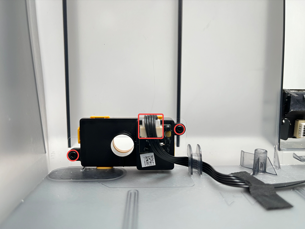
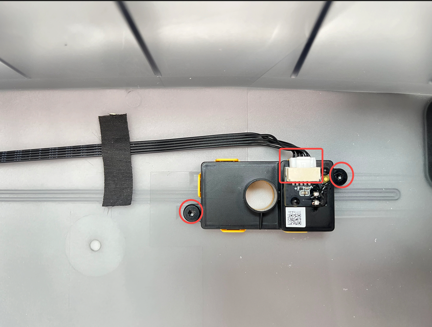
Reseat the two cables connected to the air intake and exhaust vent assembly (see image below).
If reseating the vent cables does not resolve the issue, replace the vent assembly. Since cable failures are rare, you may replace only the vent assembly first without replacing the cables. If the issue persists after replacing the vent assembly, proceed to replace the cables as well.
¶ Replace the Vent Assembly
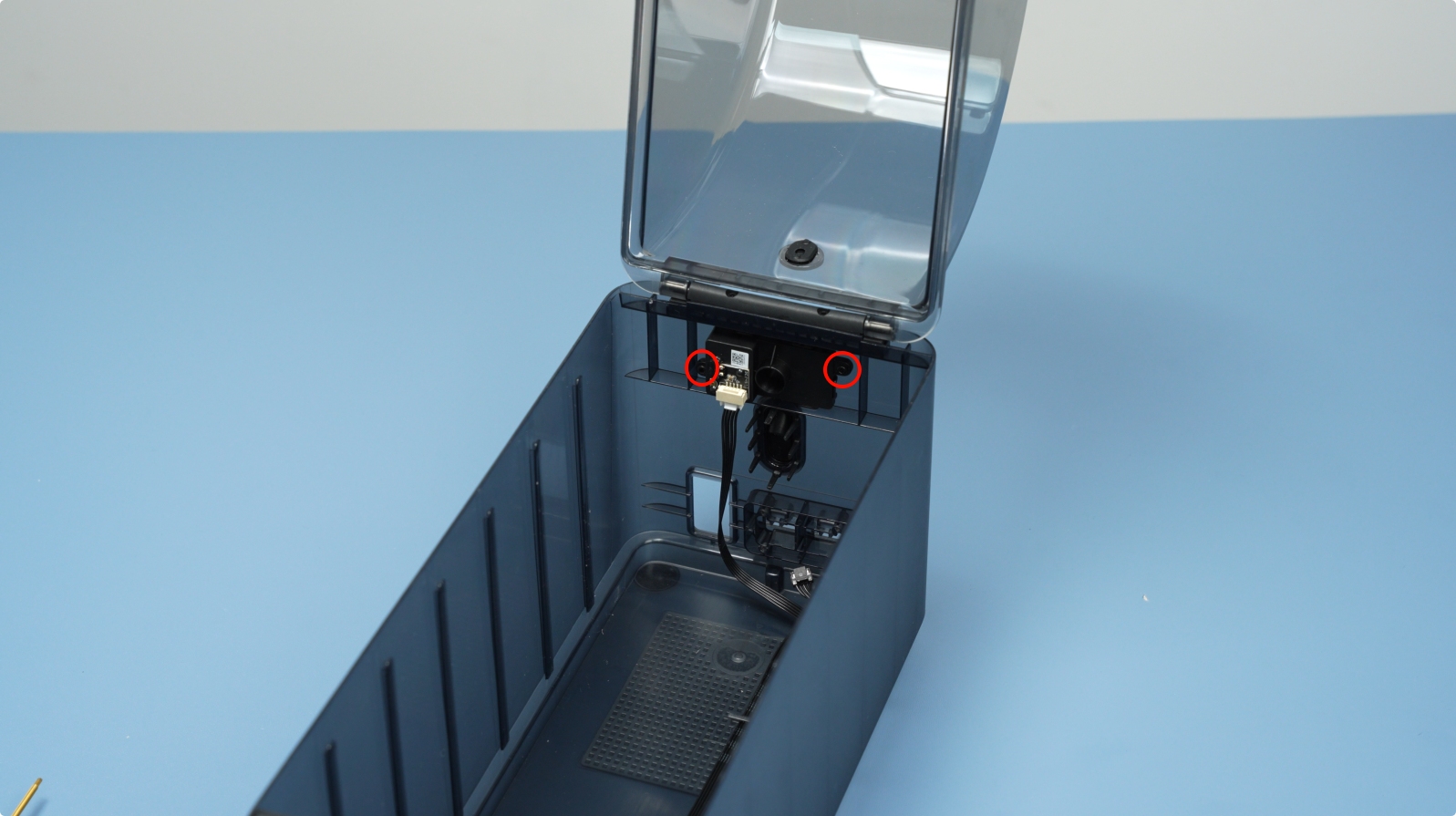
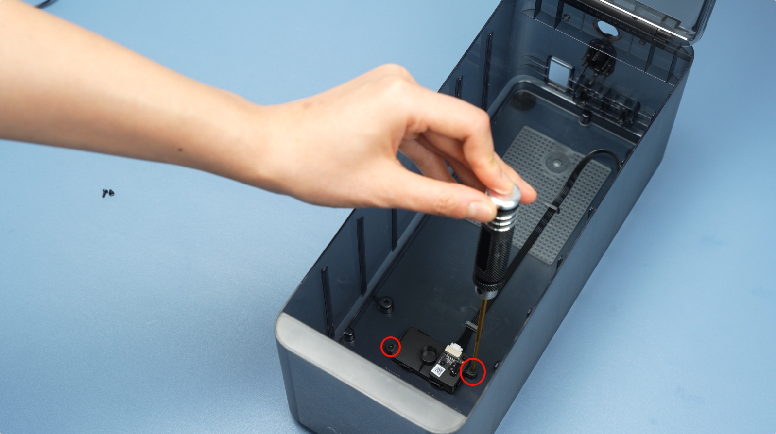
¶ Step 1 - Install the Air Inlet Unit
Note: Distinguish between short and long cables. Short cables connect to the rear, and long cables connect to the bottom. Secure each unit with two screws (BT2×4).
 |
 |
¶ Step 2 - Install the AMS HT Main Frame
Connect the two cables:
- Mainboard communication cable (14-pin).
- Mainboard power cable (2-pin).
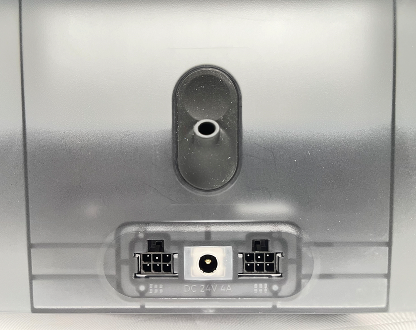
Connect the power socket cable to the mainboard and reinstall the insulation sleeve.
Note: Polarity does not matter here.
Connect the front screen cable and secure it in the channel.
 |
 |
Hook the protruding cables with your fingers and install the main frame into the bottom cover.
 |
 |
Ensure the main frame is fully seated and secure it with two bottom screws (BT3×8).
 |
 |
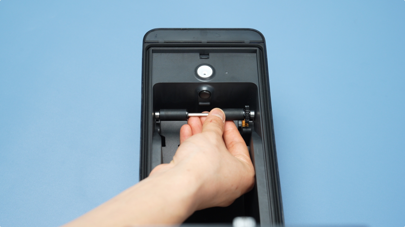
¶ Step 3 - Install the Active and Driven Support Shafts
Press the Active Support Shaft into the front slot until it clicks. Align the black gear with the yellow gear inside the main frame.

Press the Driven Support Shaft into the main frame until it clicks.

Note: After installation, manually rotate the shafts to ensure smooth movement.
¶ Step 4 - Insert the PTFE Tube into the AMS HT Back
Push the PTFE tube into the rear of the AMS HT. Pull it gently to confirm it is secure.
¶ End Notes
We hope the detailed guide provided has been helpful and informative.
If this guide does not solve your problem, please submit a technical ticket, we will answer your questions and provide assistance.
If you have any suggestions or feedback on this Wiki, please leave a message in the comment area. Thank you for your support and attention!