¶ Rubber Screws
¶ Applicable models of printers
H2D
¶ When to use?
During transportation or maintenance, accidental impacts may cause the rubber screws to become dislodged; you can refer to this guide for handling such situations.
¶ Tools and materials needed
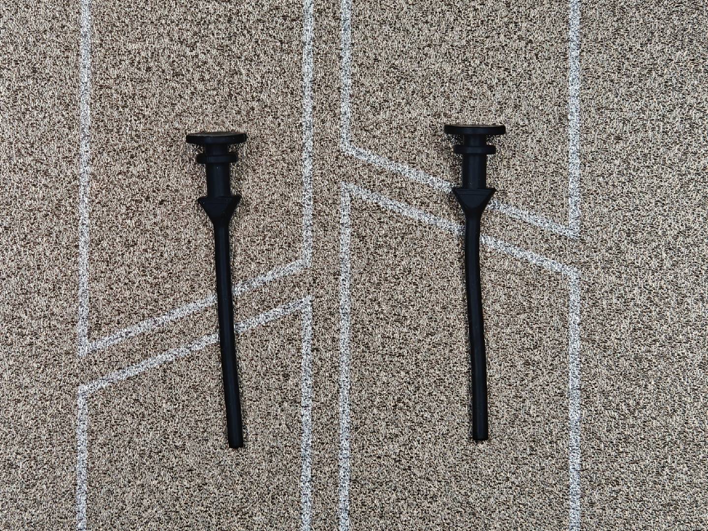
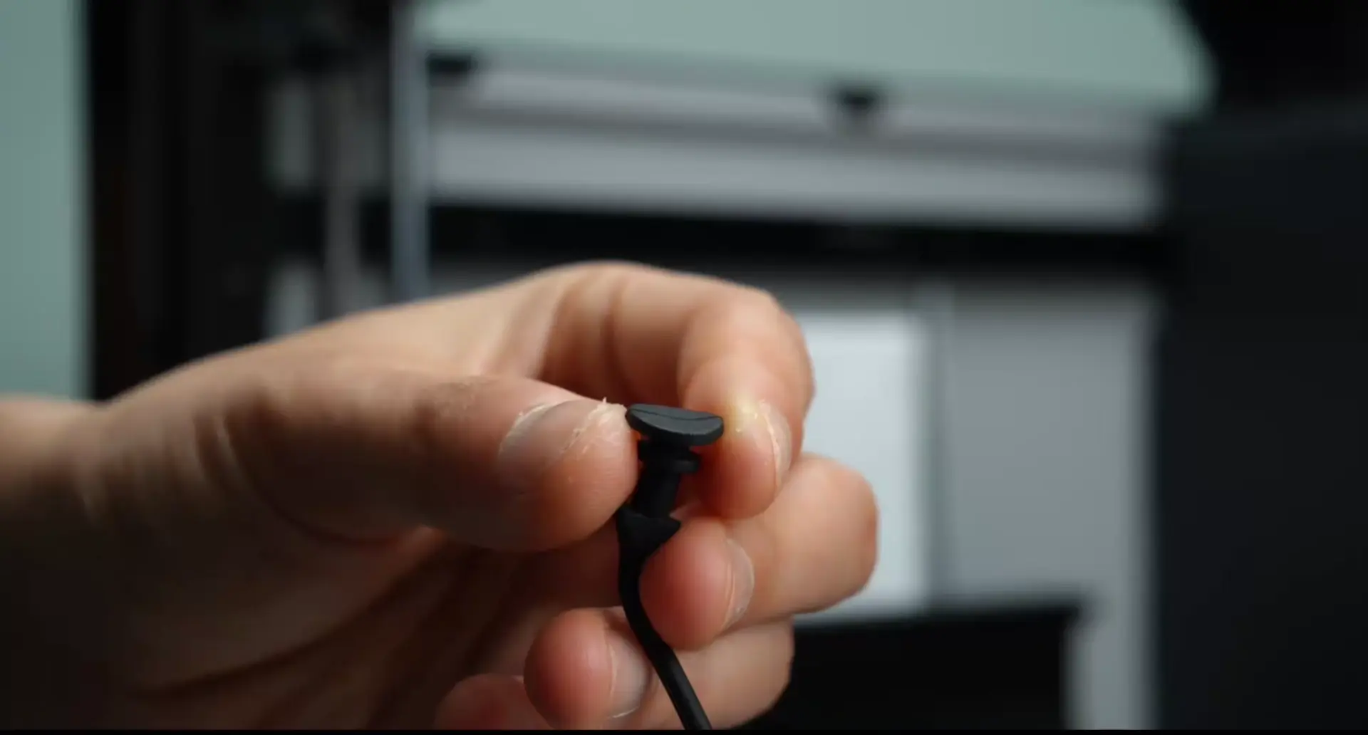
- Rubber screws
- H2.0 Allen key
- tweezers (optional)
- 10 minutes
¶ Safety Warning
IMPORTANT!
It's crucial to power off the printer before conducting any maintenance work, including work on the printer's electronics and tool head wires. Performing tasks with the printer on can result in a short circuit, leading to electronic damage and safety hazards.
During maintenance or troubleshooting, you may need to disassemble parts, including the hotend. This exposes wires and electrical components that could short circuit if they contact each other, other metal, or electronic components while the printer is still on. This can result in damage to the printer's electronics and additional issues.
Therefore, it's crucial to turn off the printer and disconnect it from the power source before conducting any maintenance. This prevents short circuits or damage to the printer's electronics, ensuring safe and effective maintenance. For any concerns or questions about following this guide, we recommend submitting a technical ticket regarding your issue and we will do our best to respond promptly and provide the assistance you need.
¶ Operation Steps
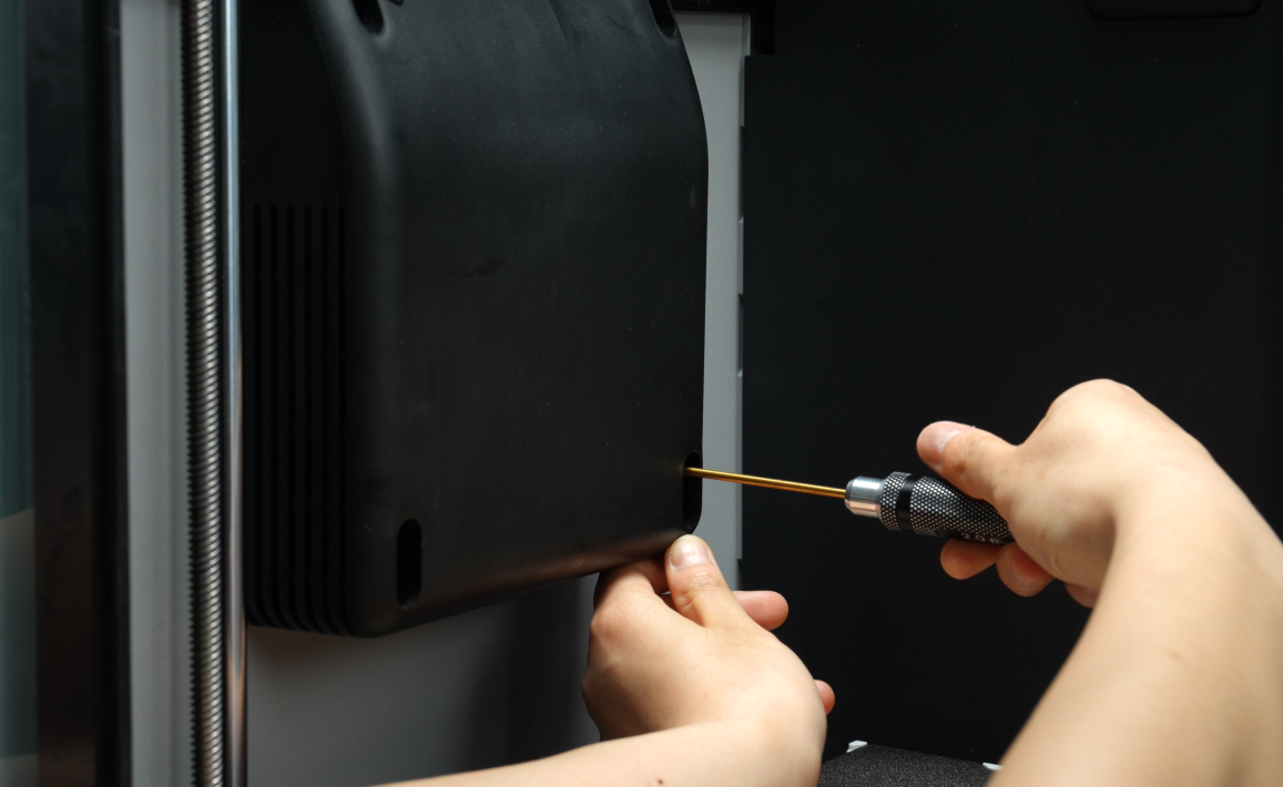
¶ Remove the Auxiliary Part Cooling Fan
Use an H2.0 Allen key to remove the two fixing screws (BT3x16) at the bottom of the auxiliary part cooling fan.
 |
 |
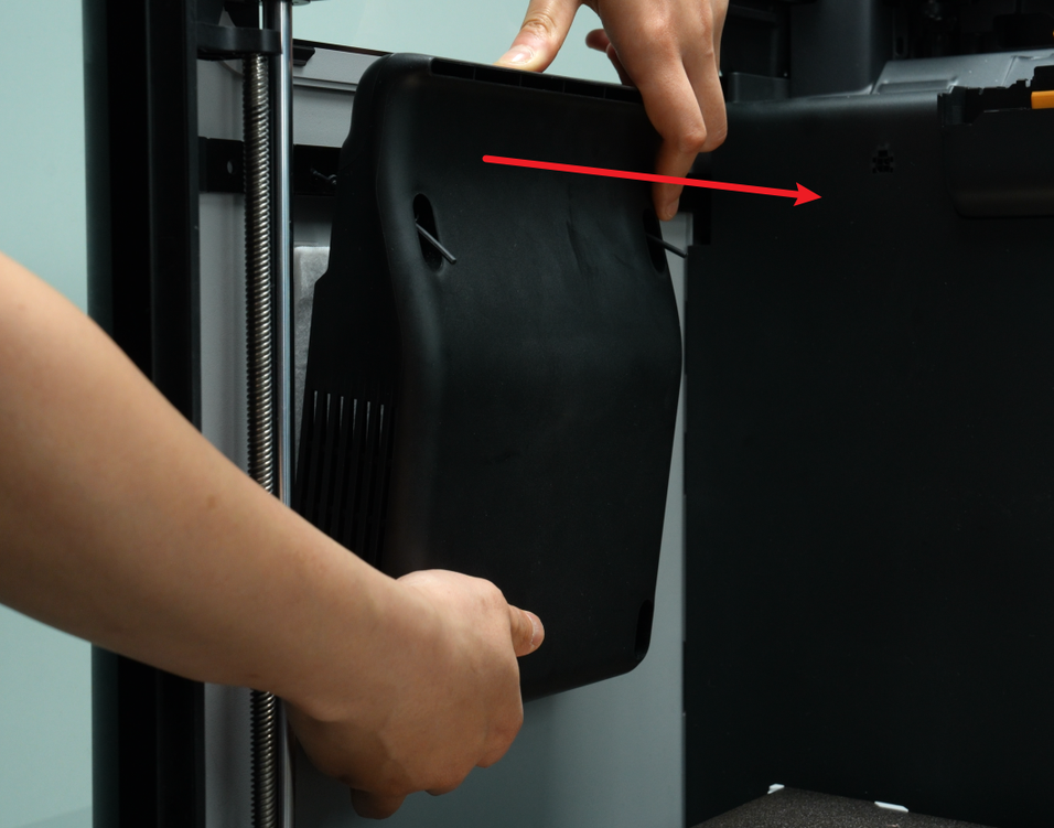
If the rubber screws are not completely removed, you can hold the auxiliary part cooling fan and slowly pull the fan out.
¶ Install the Rubber Screws
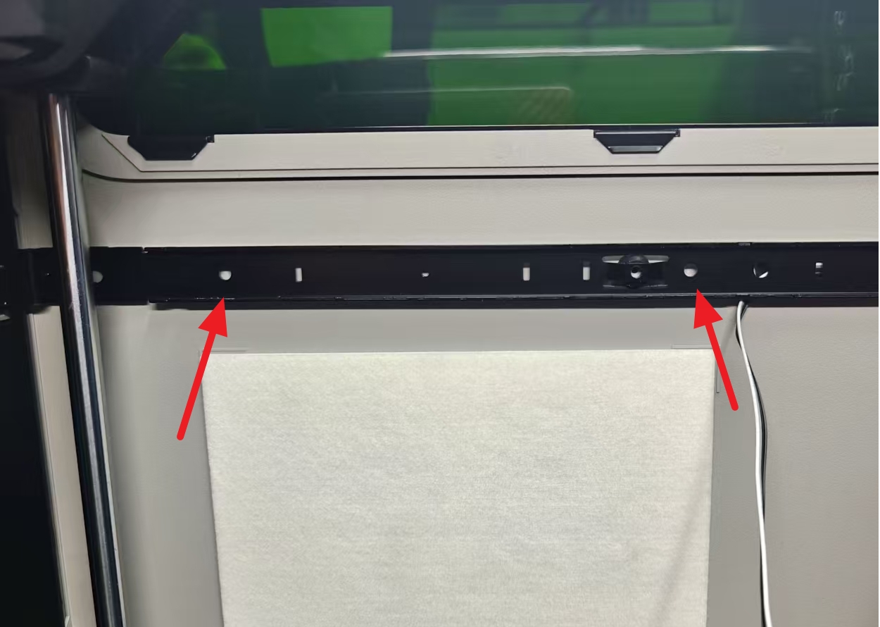
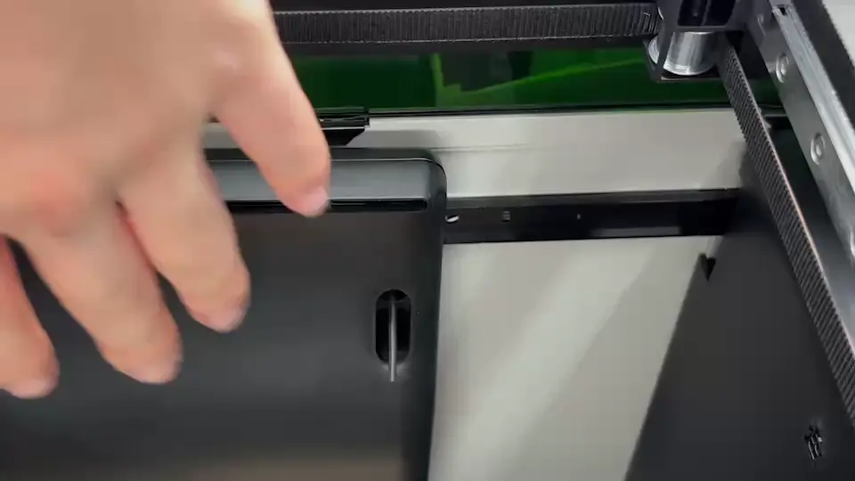
In order to ensure that there is a gap between the side panels and the beam to facilitate the installation of rubber screws, after removing the fan, you need to remove the fixing screws of the middle beam and side panels, and install the rubber screws into the two holes shown in the figure below.
 |
 |
-
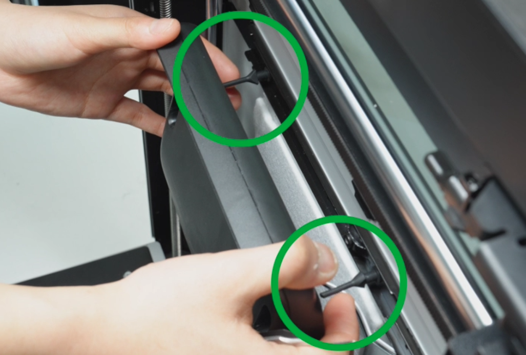
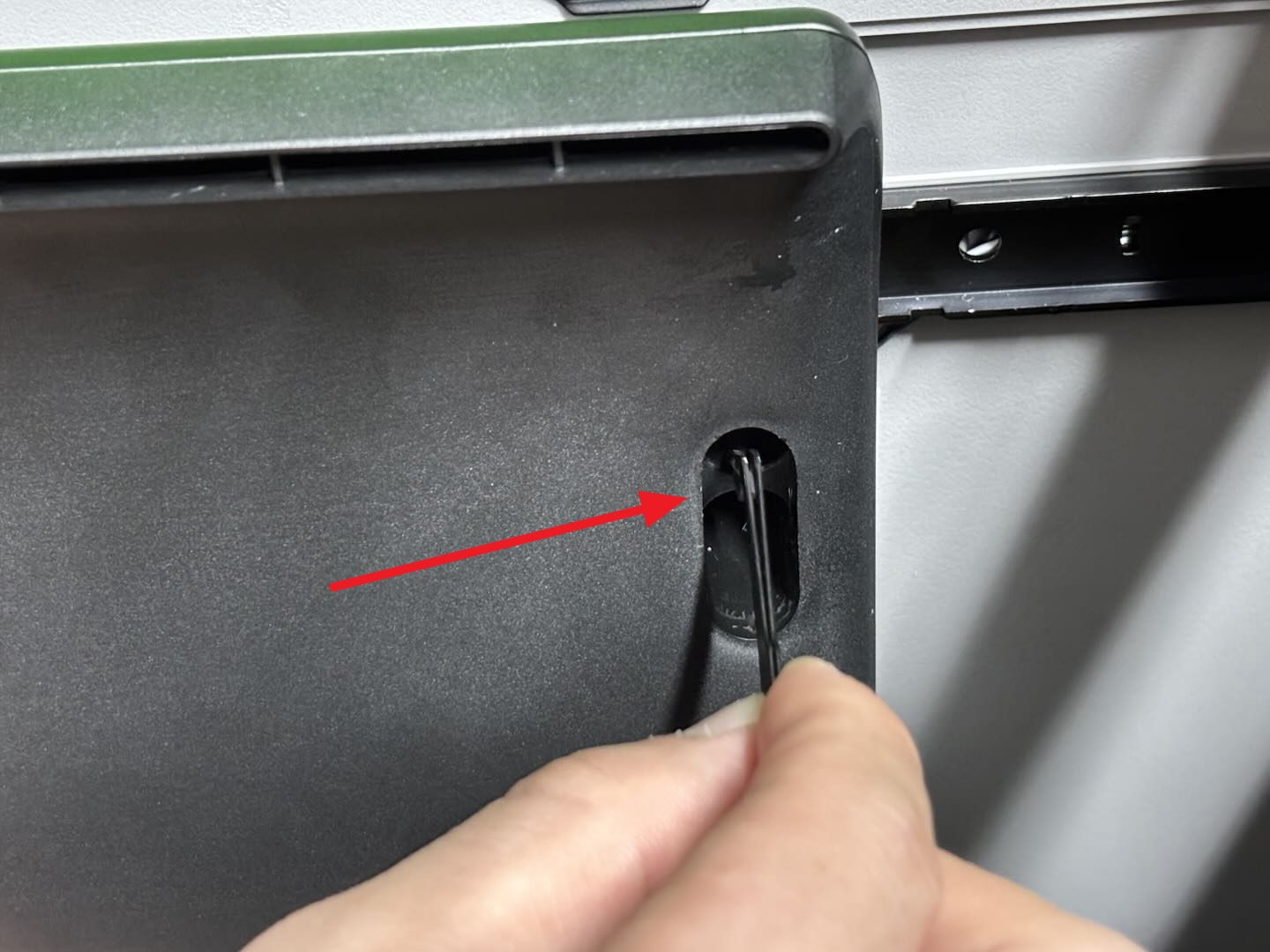
First, fold the rubber screw in half from the middle, gently push the side panel backwards, and insert it into the round hole. At this time, you need to press inwards and rotate slowly.
-
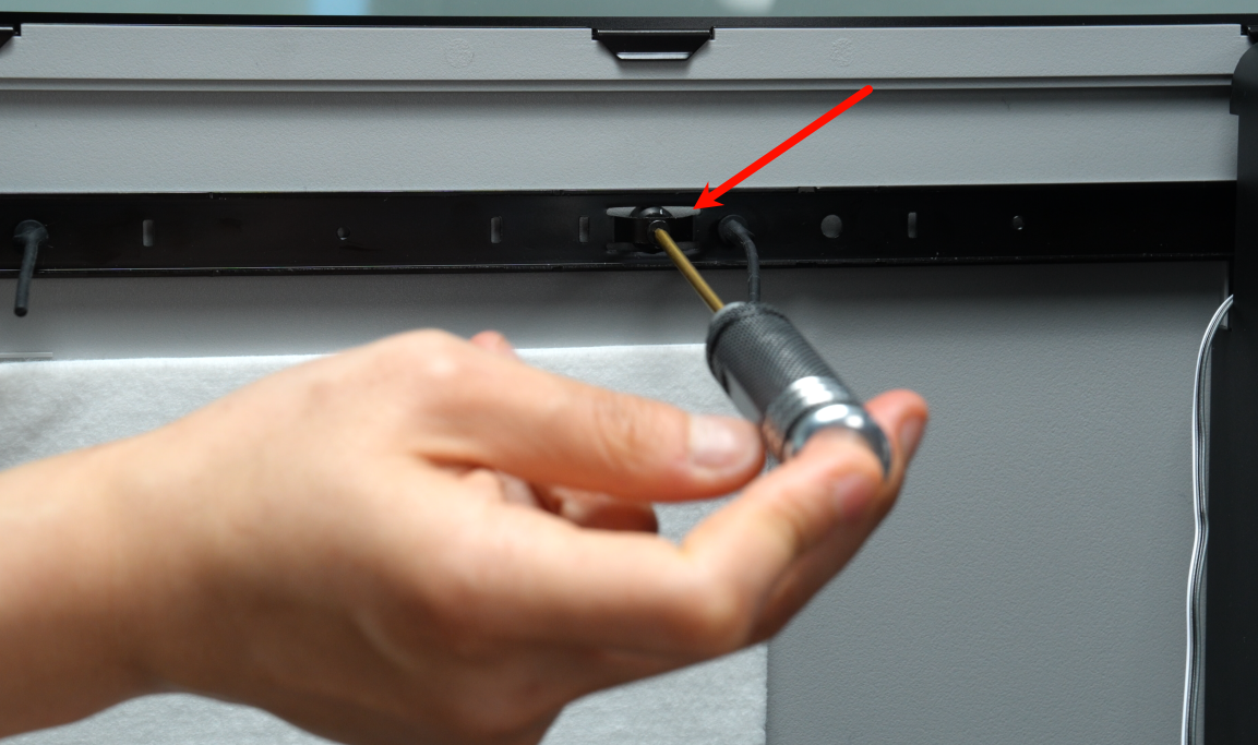
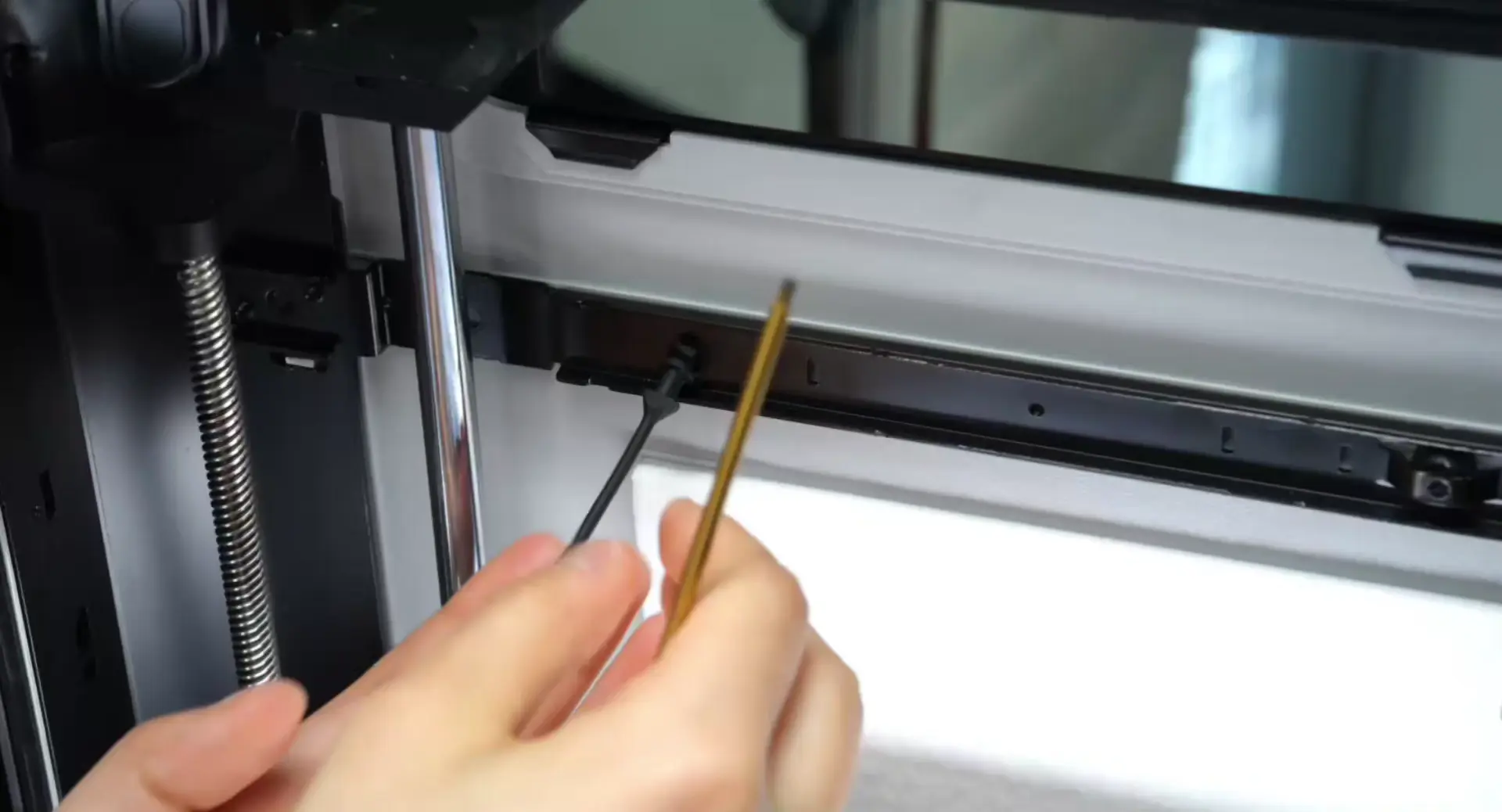
After the rubber screw has entered part of the way, you can use an Allen key to help press it in.
-
Tighten the fixing screws between the beam and side panel.
¶ Install the Auxiliary Part Cooling Fan
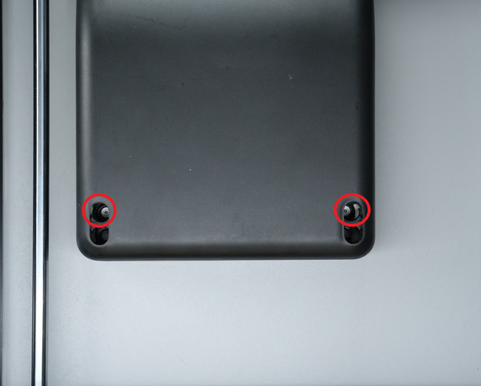
First, align the holes at the bottom of the fan and lock the two screws at the bottom.
|
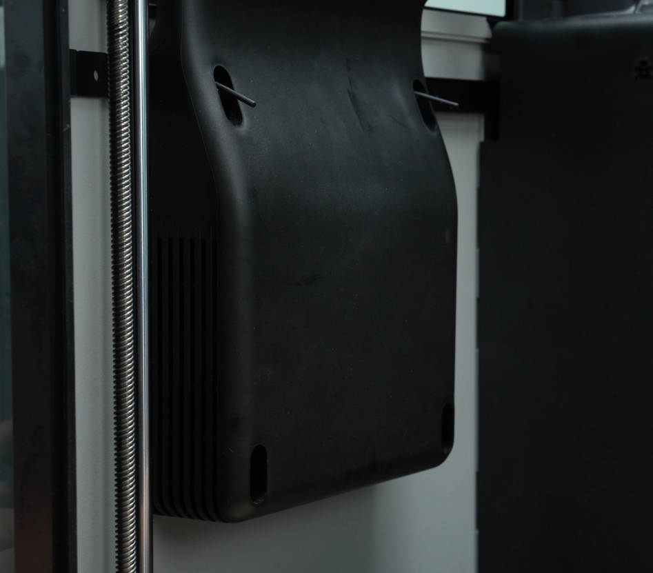
Align the rubber screw with the hole on the top of the fan and insert it, then pull the rubber screw back to fix the fan.
 |
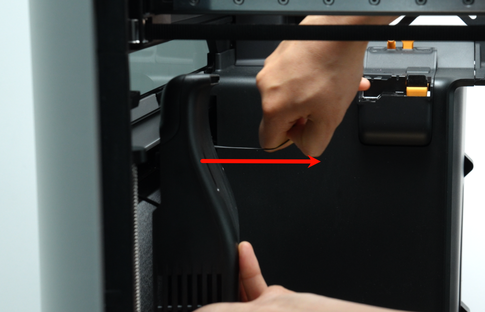 |
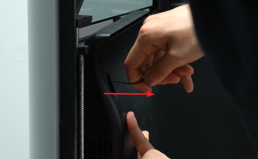 |
Note: When installing the fan, there may be two situations that might occur.
- If it is difficult to pull out, it might be necessary to use tweezers to assist in pulling out the rubber screws.
2. If the rubber screws are too short to be passed through directly, or if there are no tweezers or other tools available, then the rubber screws need to be replaced.
The picture below shows the state where the auxiliary part cooling fan is correctly installed.
¶ End Notes
We hope the detailed guide provided has been helpful and informative.
If this guide does not solve your problem, please submit a technical ticket, we will answer your questions and provide assistance.
If you have any suggestions or feedback on this Wiki, please leave a message in the comment area. Thank you for your support and attention!