¶ Precautions:
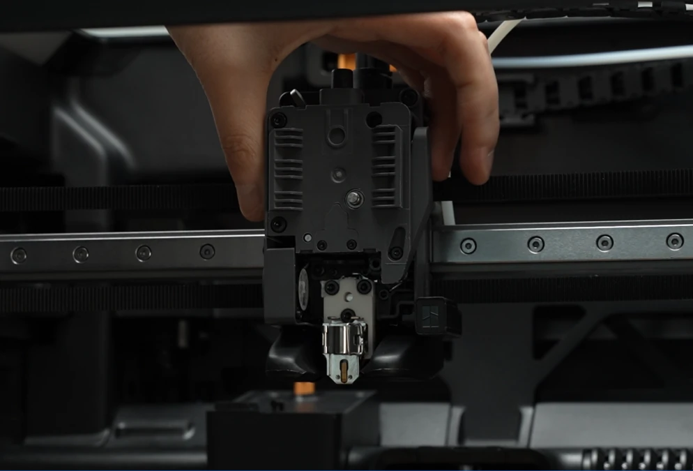
Please be sure to follow the disassembly sequence outlined in this article strictly. Especially before removing the cover of the extruder, make sure to first remove the extruder filament sensor (handle with care to avoid pulling too hard), as failure to do so may result in the wiring of the sensor broken.
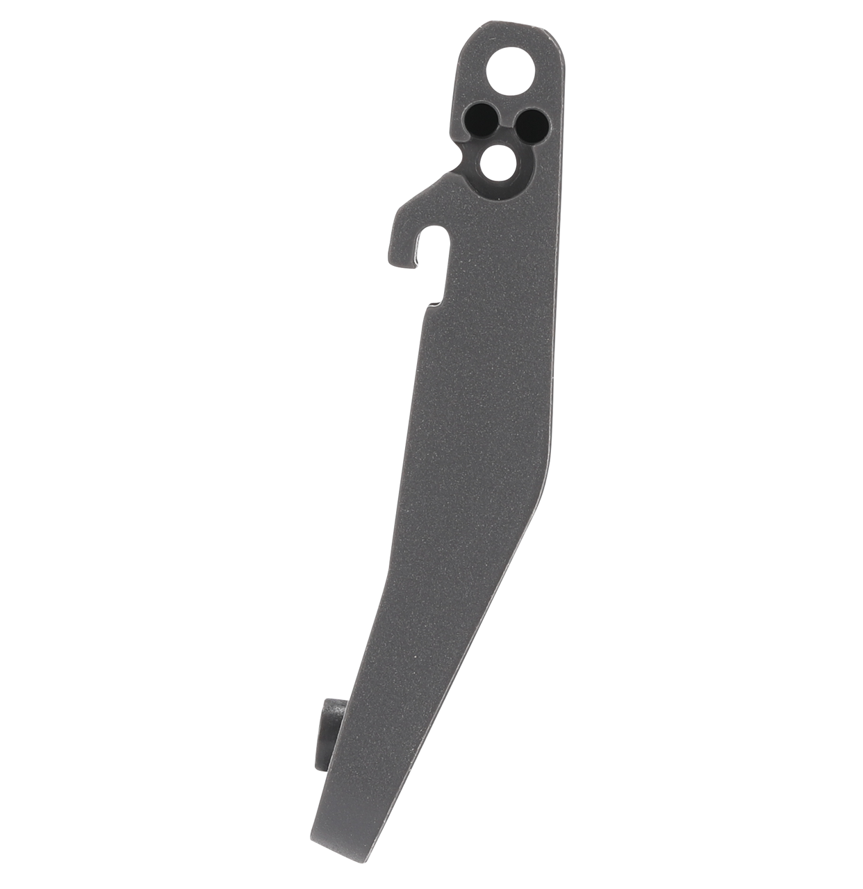
¶ Filament Cutter Lever
¶ When to Use
Replace this part if the filament cutter lever is irreversibly damaged or shows abnormal rebound during use.
¶ Tools & Materials Needed
-
H1.5 hex screwdriver
-
H2.0 hex screwdriver
-
New filament cutter lever, washer, and snap ring
¶ Remove the Old Filament Cutter Lever
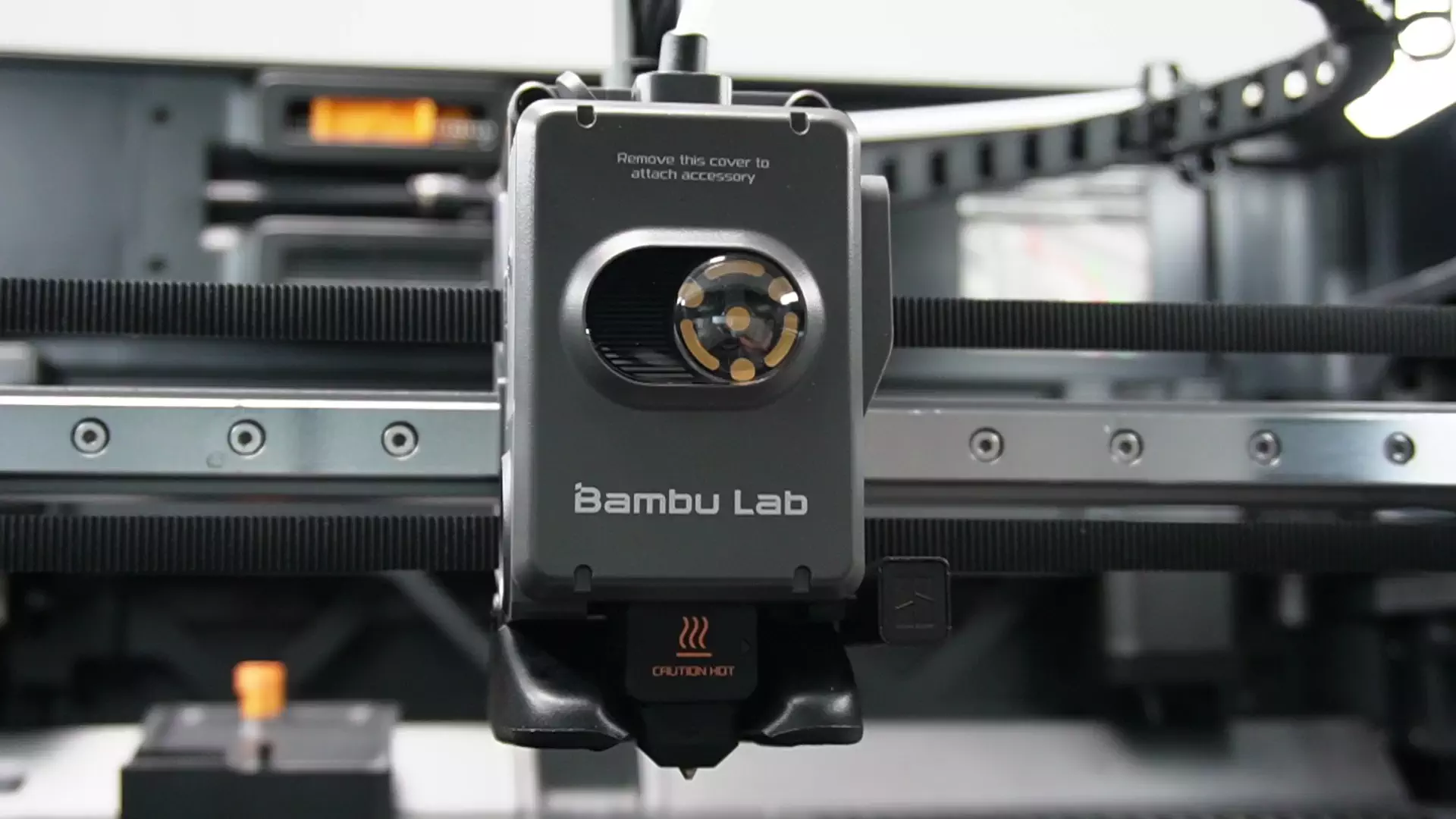
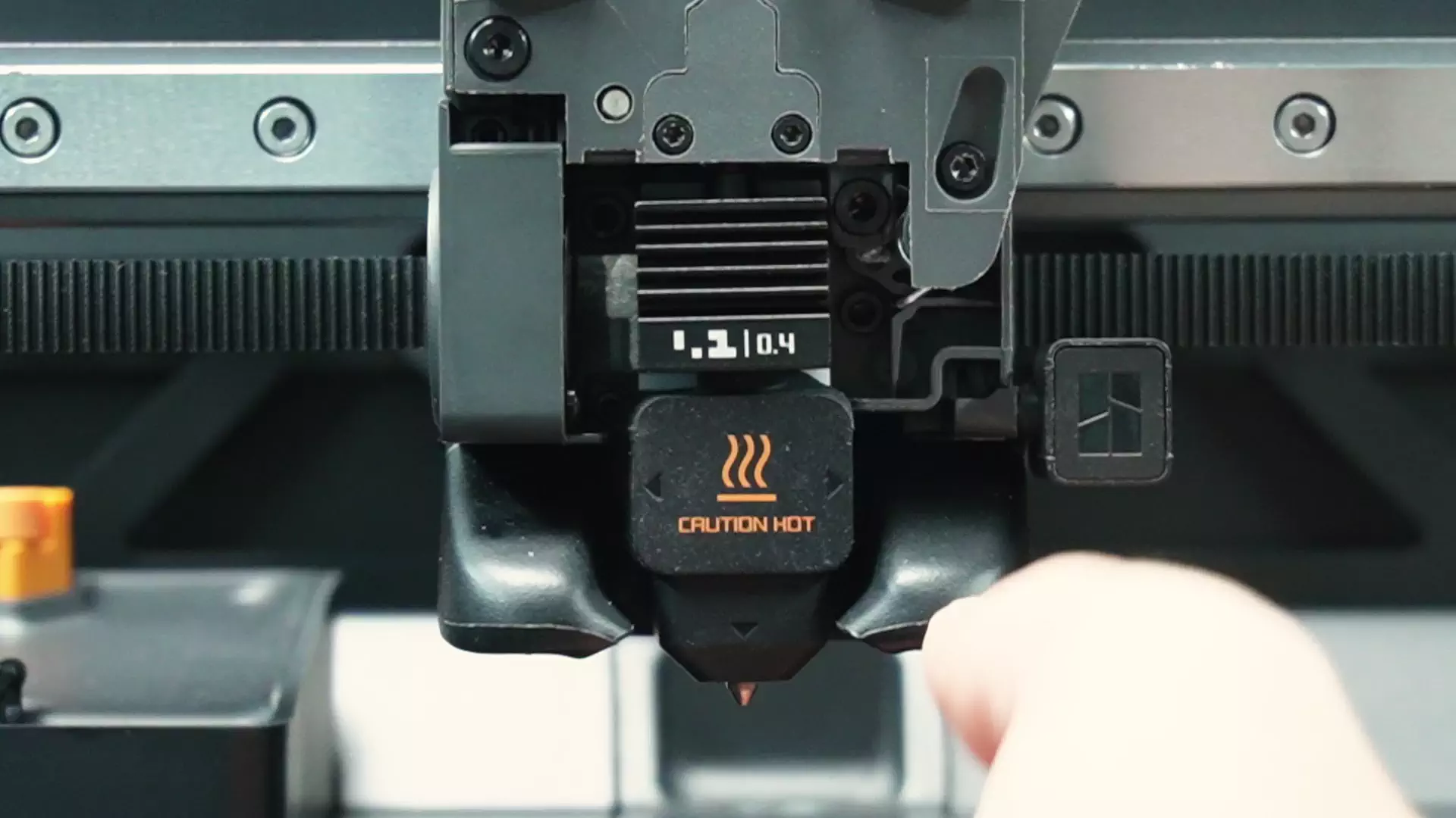
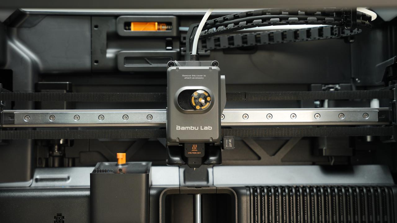
¶ Step 1. Remove the Toolhead Front Cover
Pinch the bottom of the toolhead front cover, pull it forward to remove it, and take out the rotation indicator wheel inside.
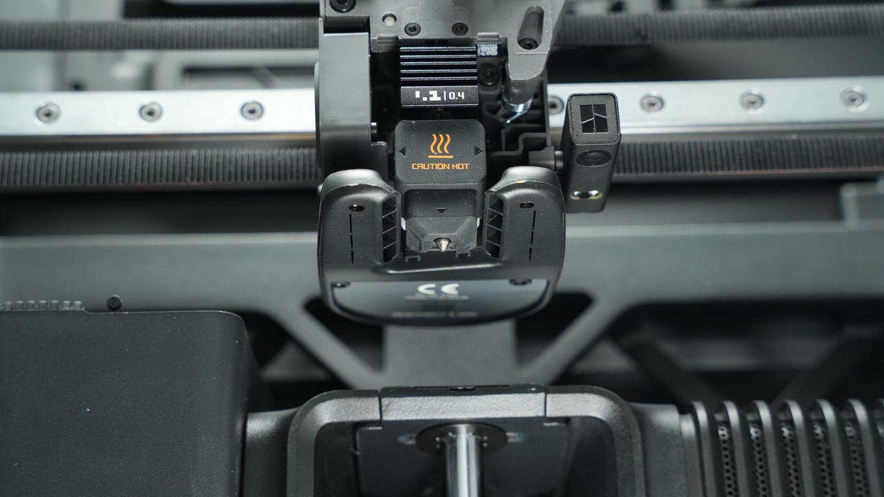
¶ Step 2. Remove the Nozzle
Remove the silicone sleeve from the nozzle. Then, open the latch on the heating assembly and take out the entire nozzle.
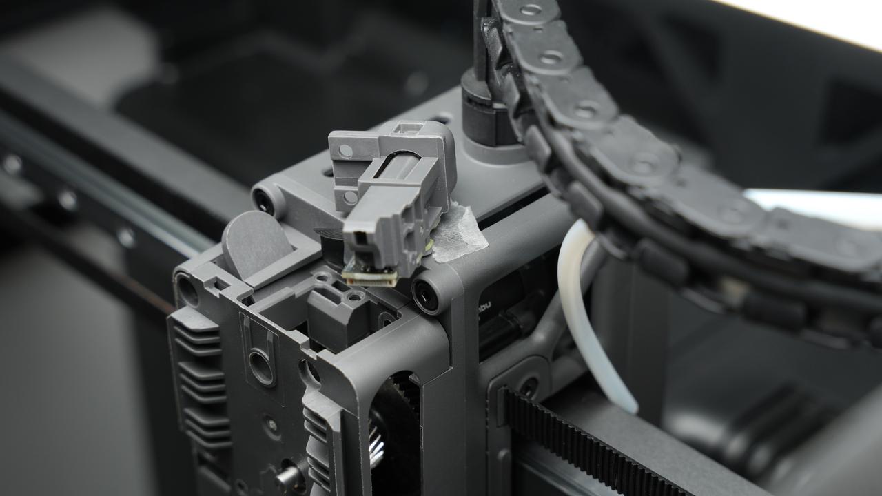
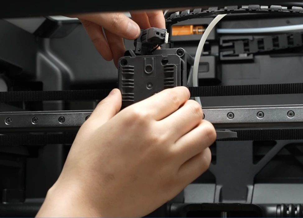
¶ Step 3. Remove the Filament Sensor Base
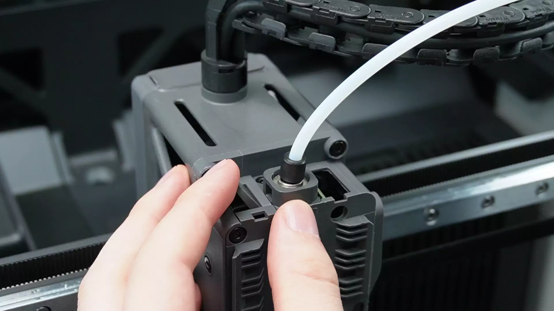
To make access easier, first detach the top PTFE tube by pressing the black connector and pulling the tube out.
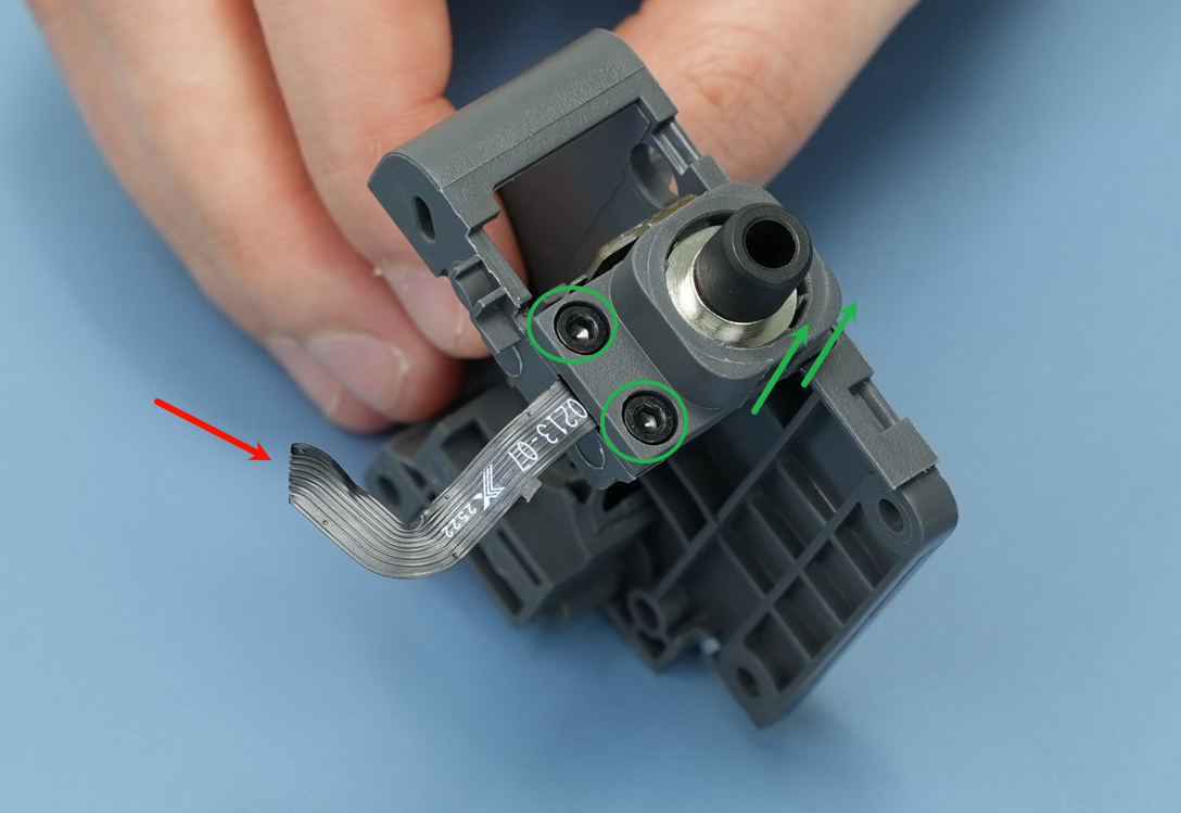
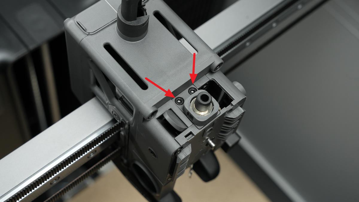
The H2.0 screwdriver is utilized to remove the two screws (BT2×6) on the top of the filament sensor base.
IMPORTANT!
A ribbon cable is still connected underneath the filament sensor base. Please handle gently to avoid pulling or breaking it.
 |
 |
|---|
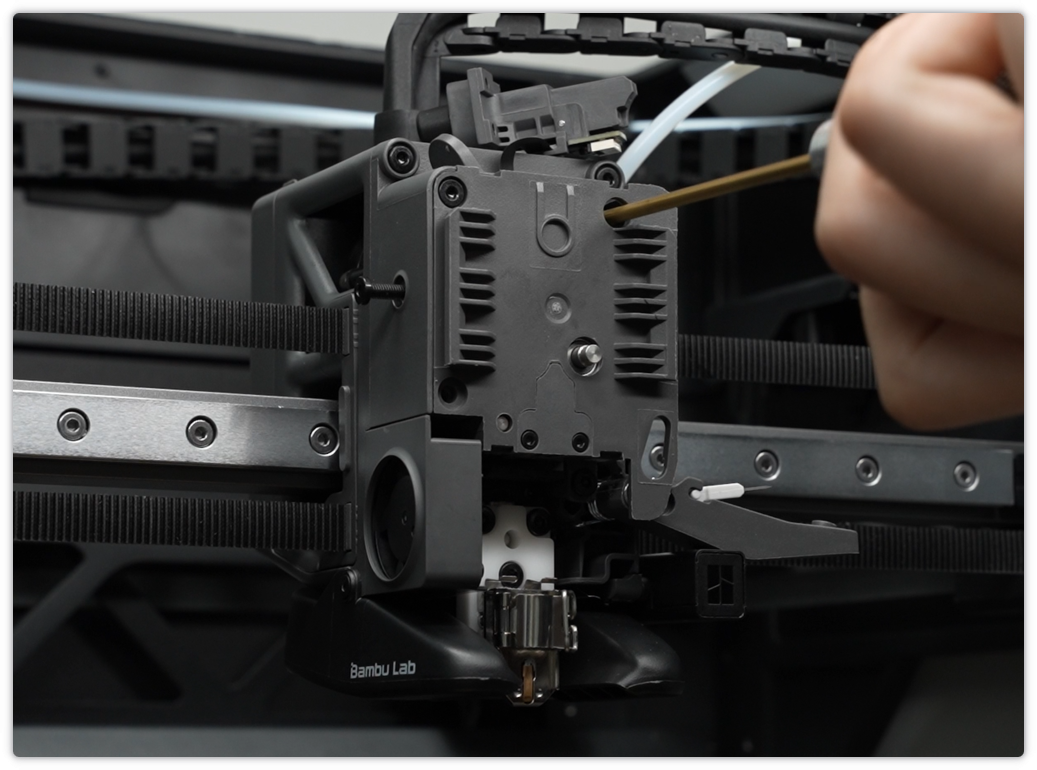
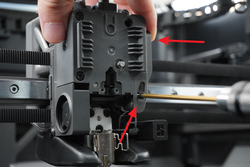
¶ Step 4. Remove the Extruder Unit Front Cover
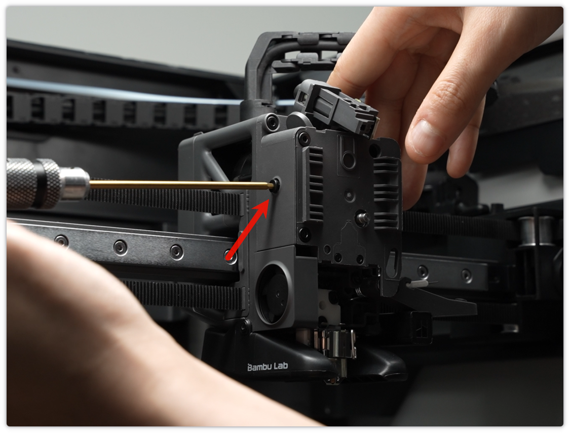
The H2.0 screwdriver is used to remove the cutter fixing screw (BT2.6 × 14.5)
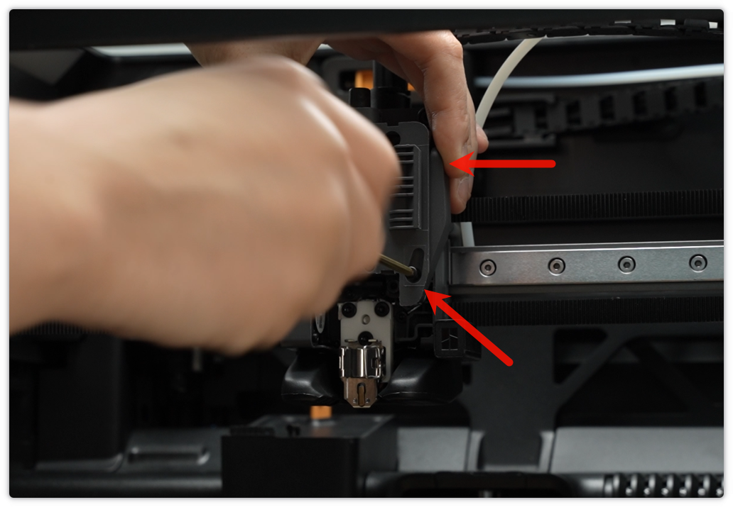
Loosen (do not fully remove) the side idler tension screw (BT3×8) to create space for removing the cover.
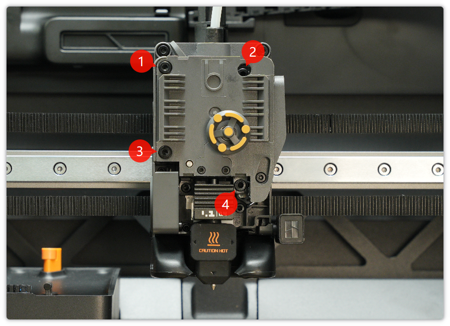
Utilize the H2.0 screwdriver to remove the four screws (BT3x8) fixing the extruder unit front cover.
 |
 |
|---|
After removing those four screws, you can take off the extruder unit front cover easily.
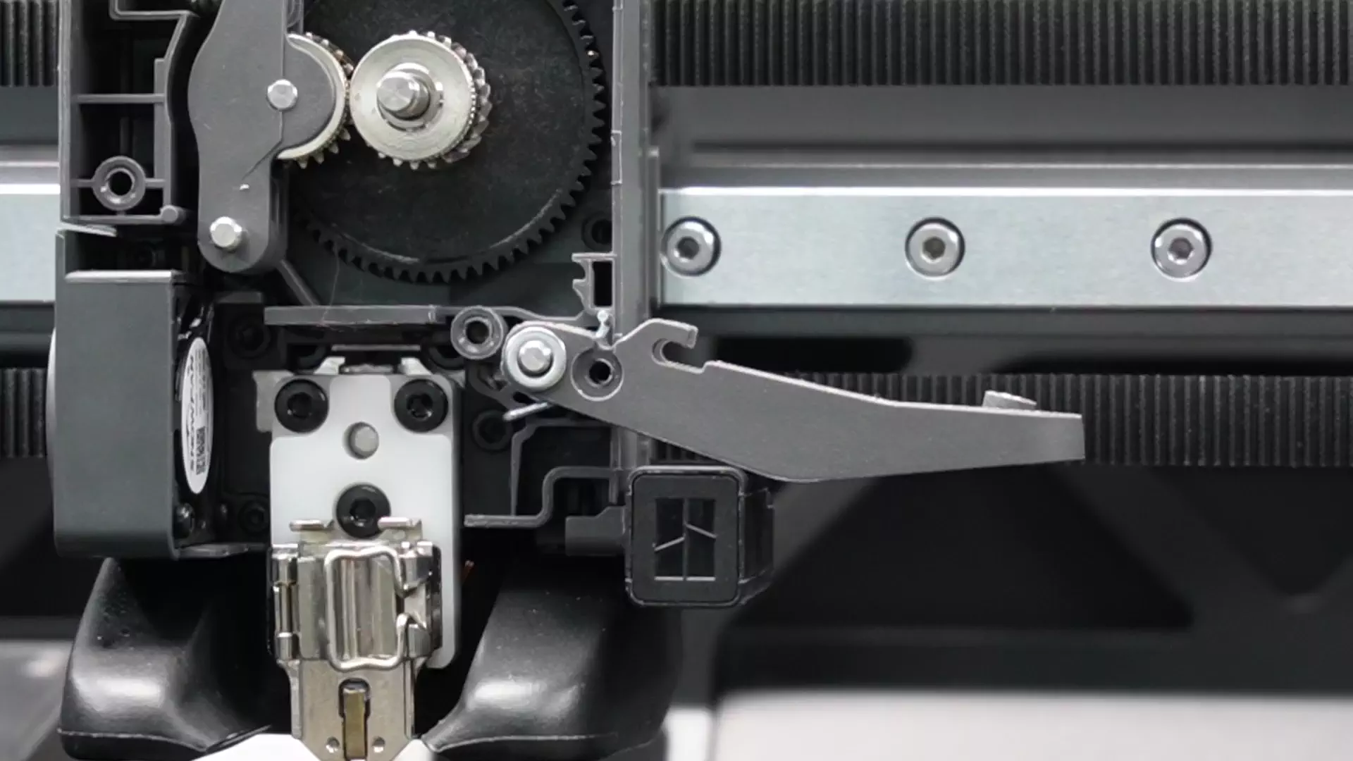
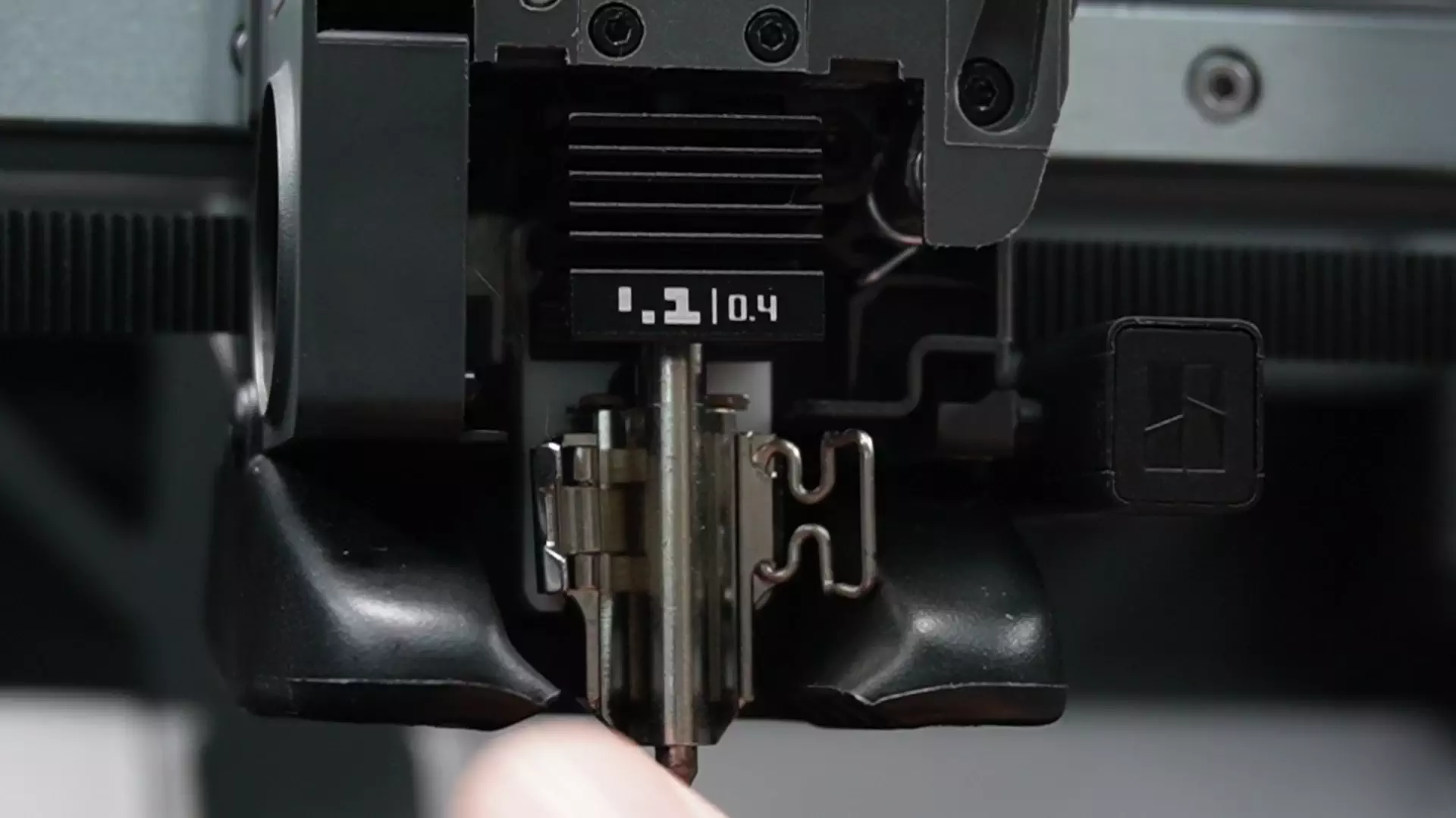
¶ Step 5. Remove the Filament Cutter Lever
We strongly recommend that you remove the blade to avoid injury.
Press the snap ring with a screwdriver or tweezers to loosen it. Then, remove the blade.
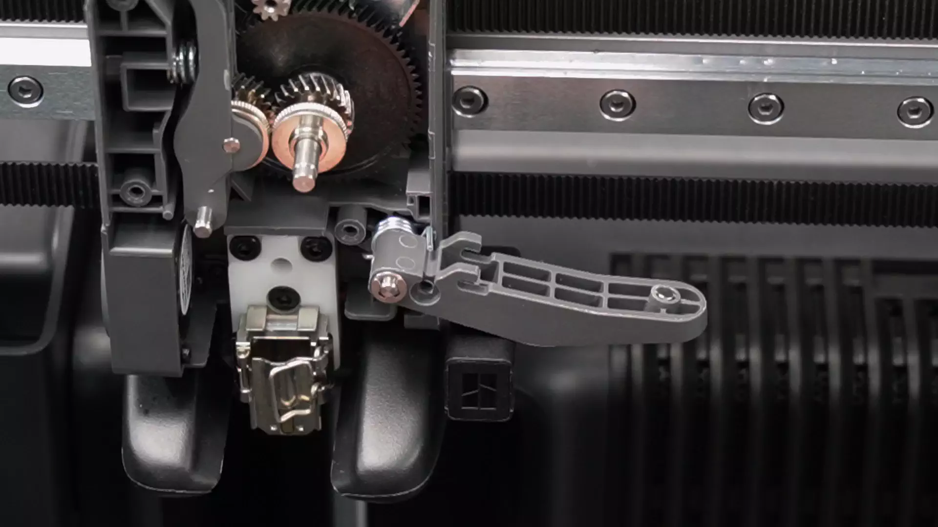
After that, remove the washer and filament cutter lever carefully.
Note: The washer and filament are small. Please keep them in a safe place to avoid loss.。
¶ Install the New Filament Cutter Lever
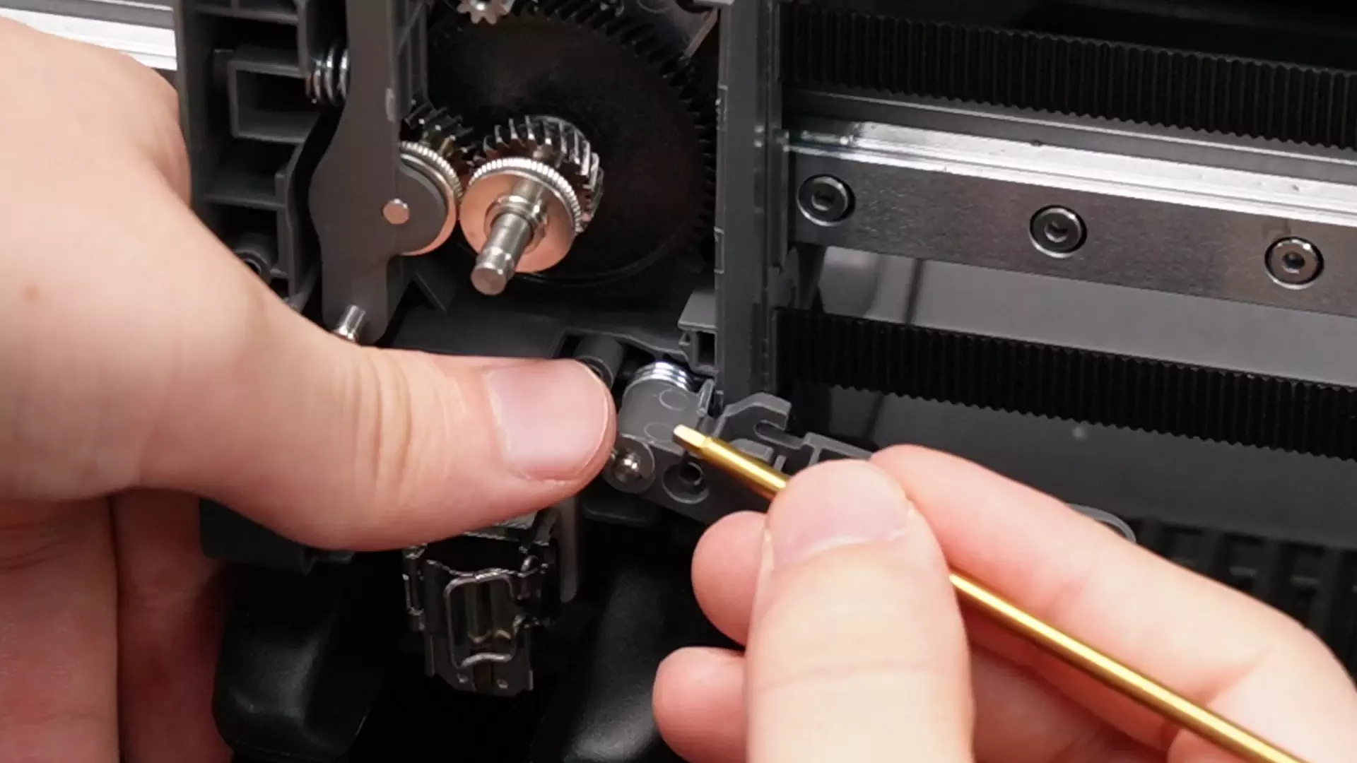
¶ Step 1. Install Filament Cutter Lever
Install in order: lever → washer → snap ring.
Utilize a screwdriver or other similar tool togently press the snap ring in.
¶ Step 2. Install the Extruder Unit Front Cover
Use the H2.0 screwdriver to secure the four screws (BT3×8) of the extruder unit front cover.
 |
 |
|---|
Re-tighten the side idler tension screw.
IMPORTANT!
If this screw cannot be tightened properly, the extruder may fail to feed filament.

Insert the blade into the slot on the lever. Then, hold the filament cutter lever and tighten the cutter fixing screw by using the H2.0 screwdriver.
¶ Step 3. Install the Filament Sensor Base
Put the filament sensor base in the right place, tighten the two screws with the H2.0 screwdriver, and reconnect the PTFE tube.

¶ Step 4. Install Nozzle
Install the nozzle and silicone sleeve as shown.
 |
 |
|---|
¶ Step 5. Install the Toolhead Front Cover
Put the rotary indicator wheel back, attach the front cover, and snap it firmly into place.
¶ Function Check
After installation, press the filament cutter lever several times to ensure it rebounds smoothly without sticking.