¶ Precautions
Special care must be taken when removing the extruder assembly to avoid tearing the ribbon cable.
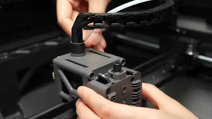
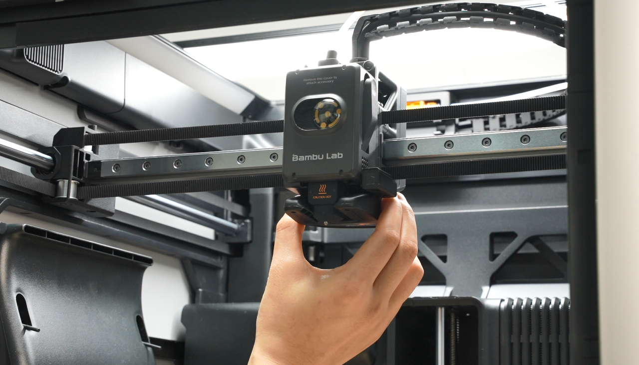
¶ Extruder Assembly
The eddy current coil is installed on the extruder, above the hot end. After proper installation, the gap between the coil and the hot end heat sink is >=0.15mm && <=0.5mm.
Spare parts include the following:
-
Extruder Assembly * 1
-
M2.5x5 * 2
-
BT3x12 * 2
-
BT2x6.5 * 2
¶ When to replace
-
Extruder component damaged;
-
Extruder motor damaged
-
Confirmed by Bambu Lab's official technical support that the extruder assembly needs to be replaced.
¶ Tools and Materials
H2S Extruder unit
-
H1.5 Hexagon Wrench
-
H2.0 Hexagon Wrech
-
30 minutes
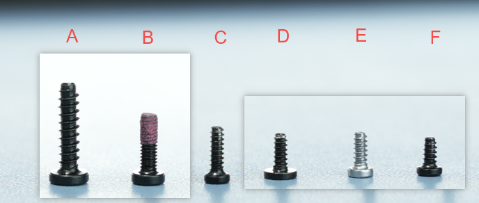
¶ Screw list involved in the disassembly and assembly process
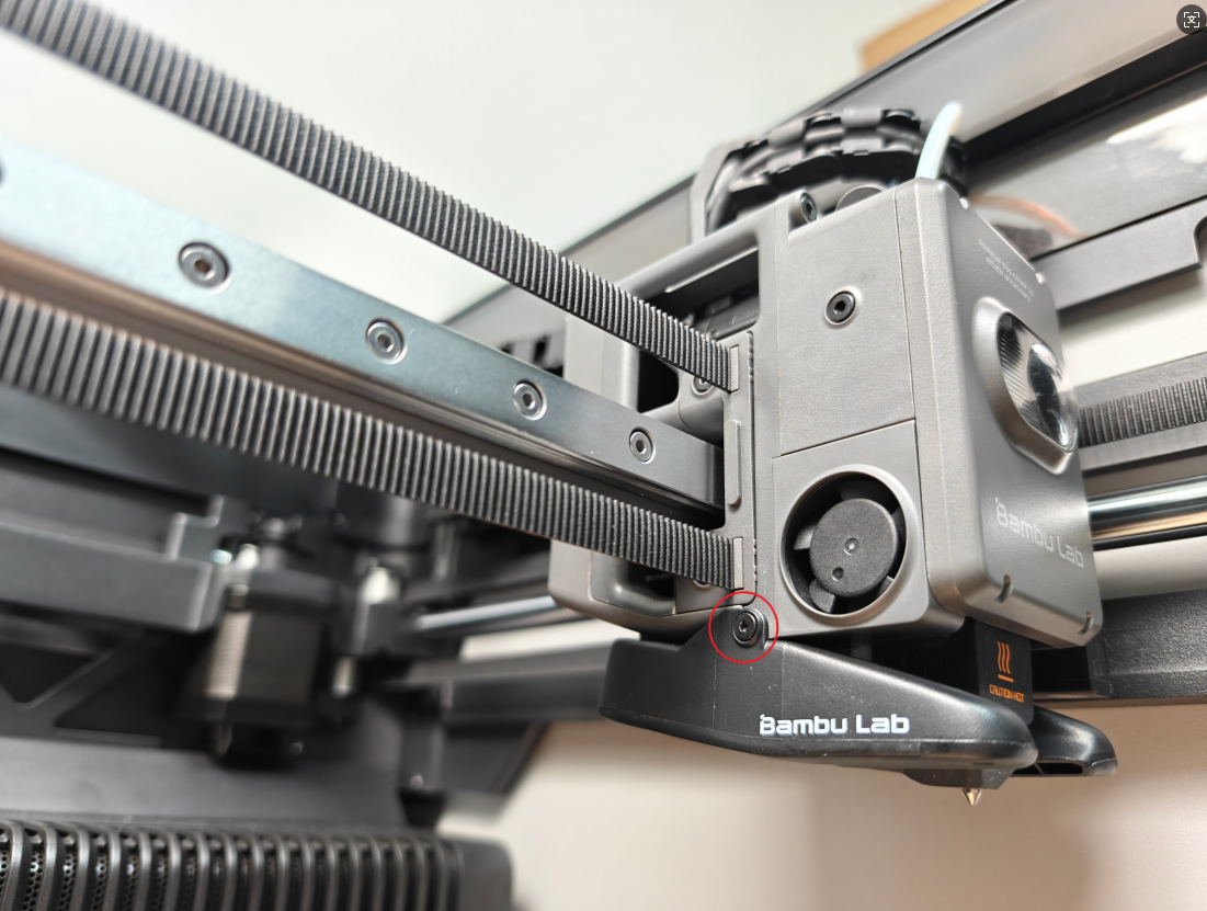
- Screw A: 2 screws above the extruder assembly: BT3x12
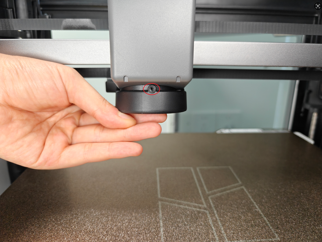
- Screw B: 2 screws below the extruder assembly: M2.5x5
- Screw C: Screws on the back of the component cooling fan (shared with the rear cover) and the rear cover of the tool head, a total of 3: BT2x6.5; Eddy current coil screws are the same size, 2 pieces. A total of 5 pieces
- Screw D: Screws on the left and right sides of the component cooling fan, a total of 2 pieces: BT2x5
- Screw E: TH board screw, total 3 pieces: BT2x5
- Screw F: Hot end fan screw, total 2 pieces: BT2x4
¶ Safety Warning
Important Reminder!
Before performing any maintenance work, be sure to turn off the printer's power supply , including maintenance on the printer's electronic components and tool head wires. Performing such operations while the printer is powered on may cause a short circuit, which can damage electronic devices and pose a safety hazard.
During maintenance or troubleshooting, you may need to disassemble components such as the hot end, thereby exposing wires and electronic components. If they come into contact with each other or with other metals or electronic components while the printer is still powered on, a short circuit may occur. This will damage the printer's electronic components and cause other problems.
Therefore, before performing any maintenance, be sure to turn off the printer and disconnect the power supply to prevent short circuits or damage to the printer's electronic components, thereby ensuring that maintenance work is carried out safely and effectively. If you have any questions about this guide, please click here to submit a ticket , and we will respond promptly and provide assistance.
¶ Remove the extruder assembly
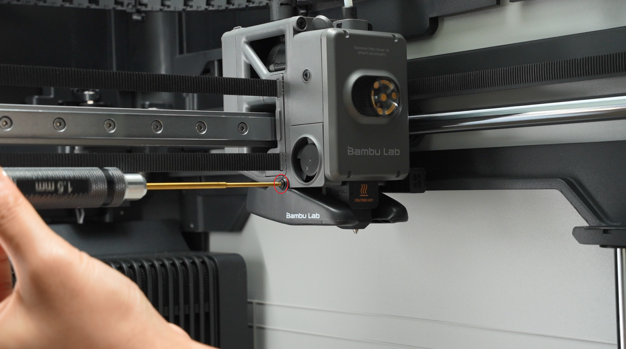
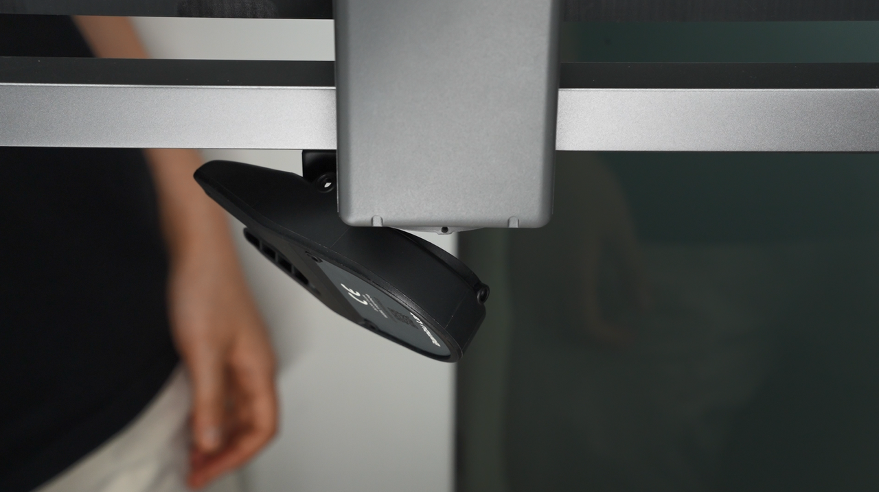
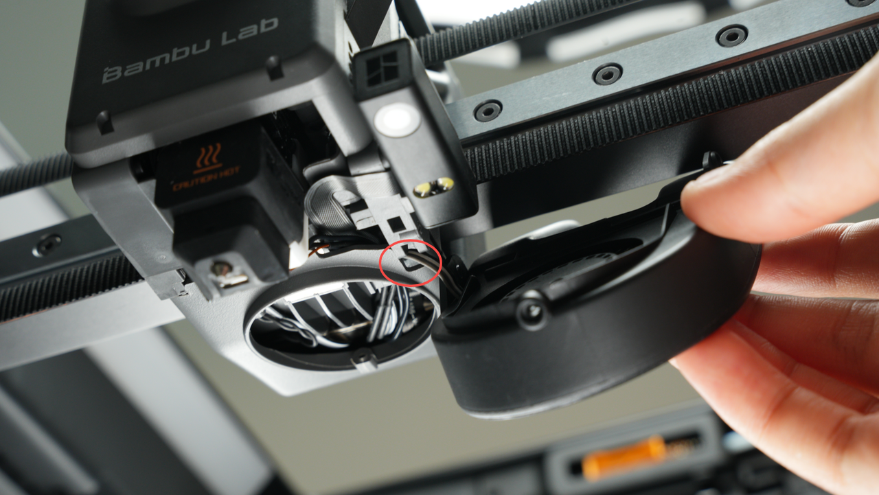
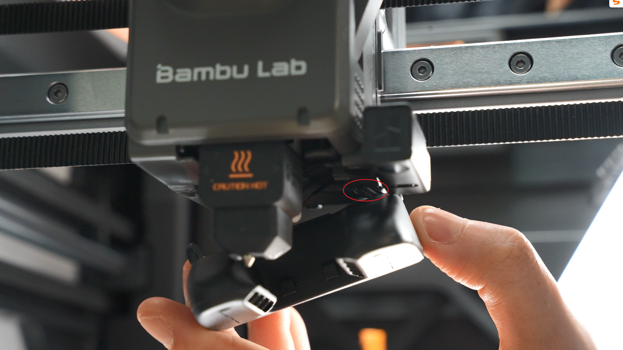
¶ Step 1: Loosen the component cooling fan
Unscrew the 3 screws of the part cooling fan, with 1 screw on the back co-locked with the tool head rear cover.
 |
 |
|---|
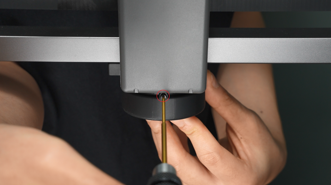
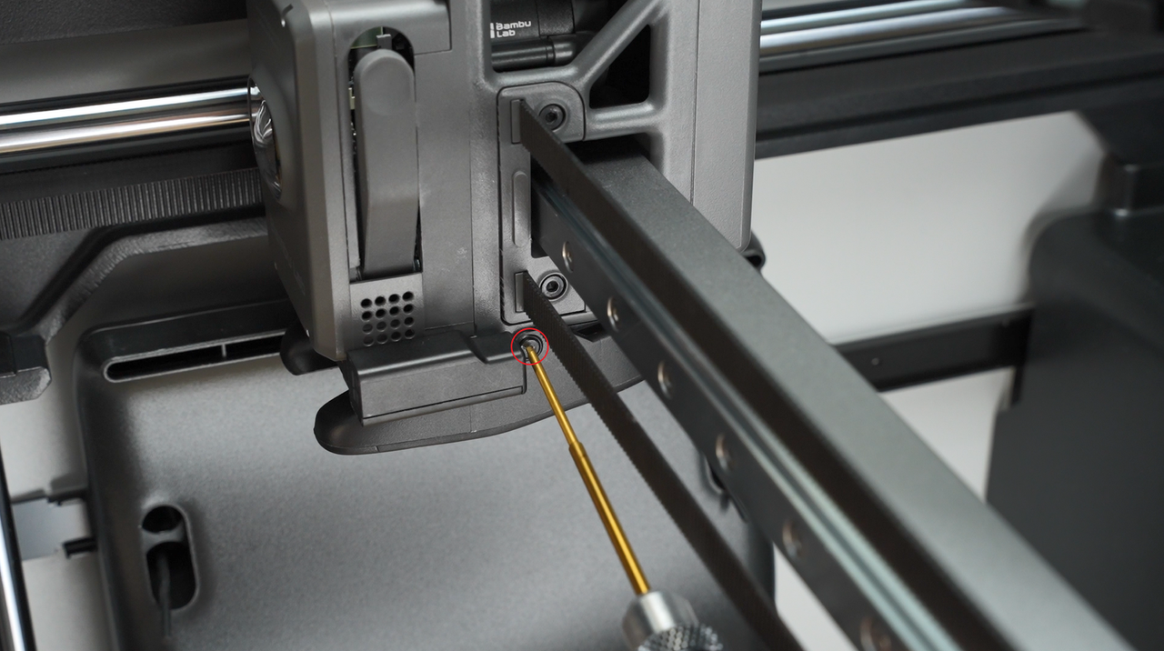
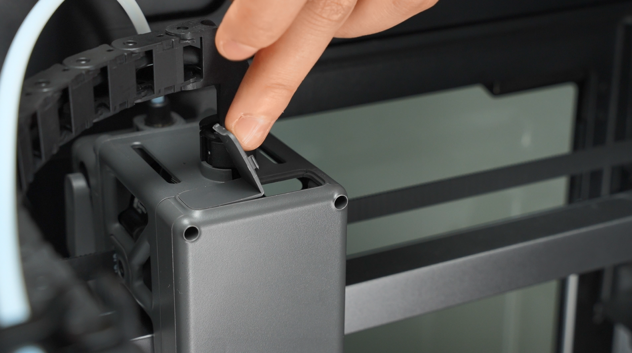
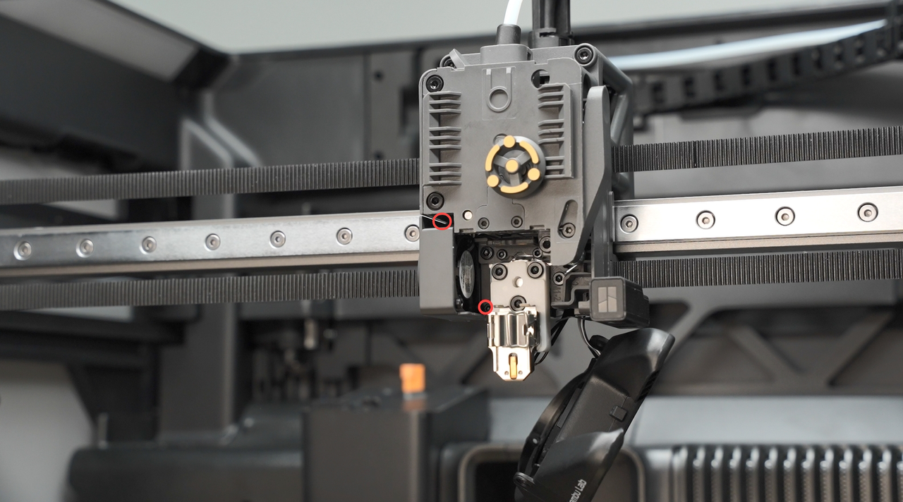
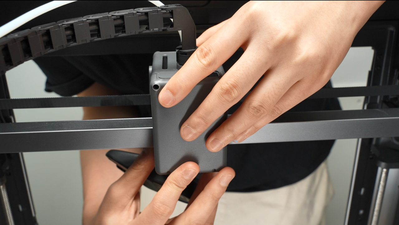
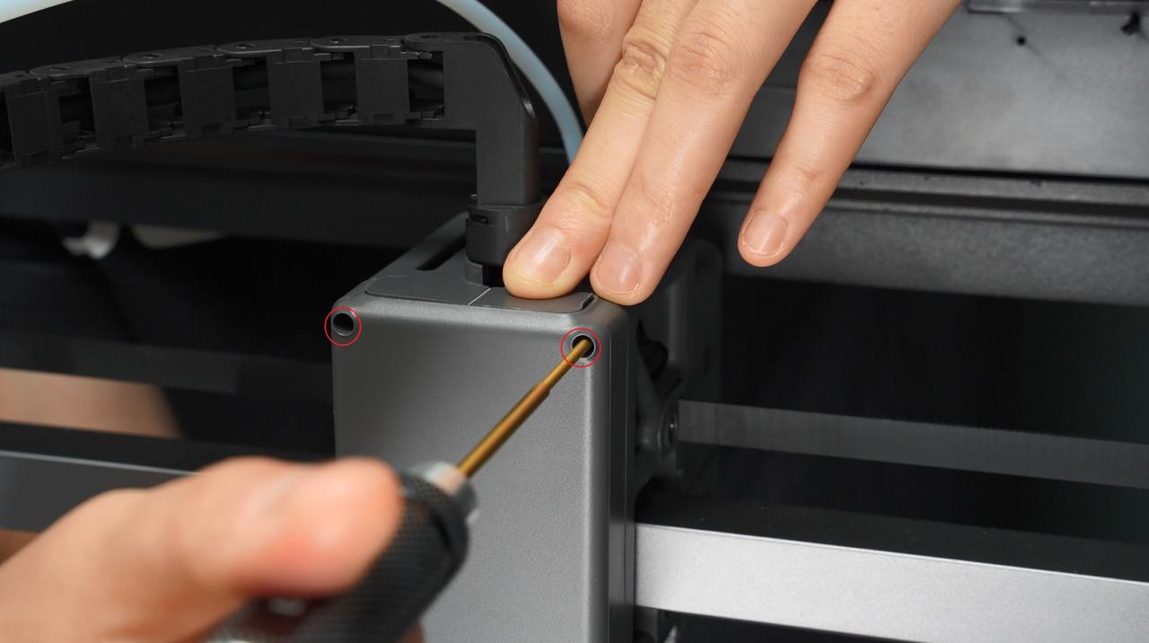
¶ Step 2: Loosen the rear cover of the tool head
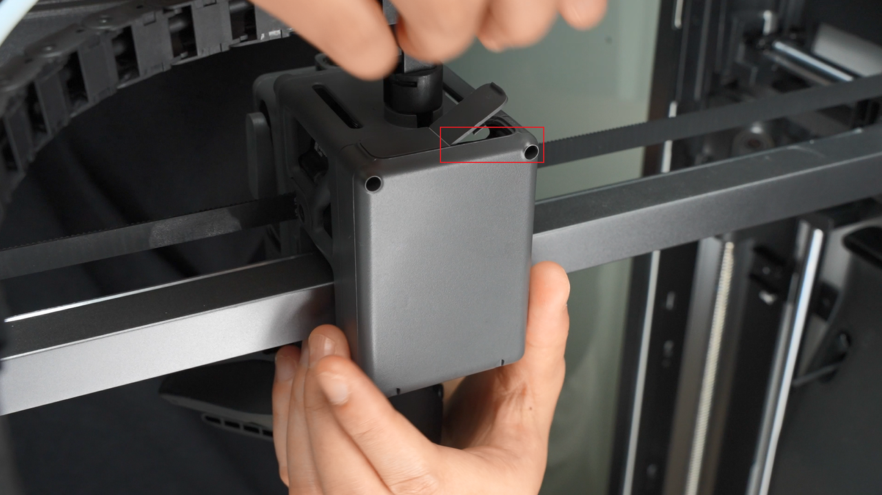
- Remove the 2 screws above the rear cover of the tool head, and open the module interface cover;
 |
 |
|---|
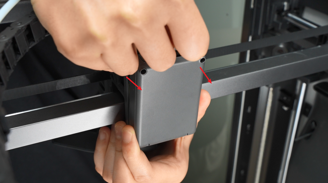
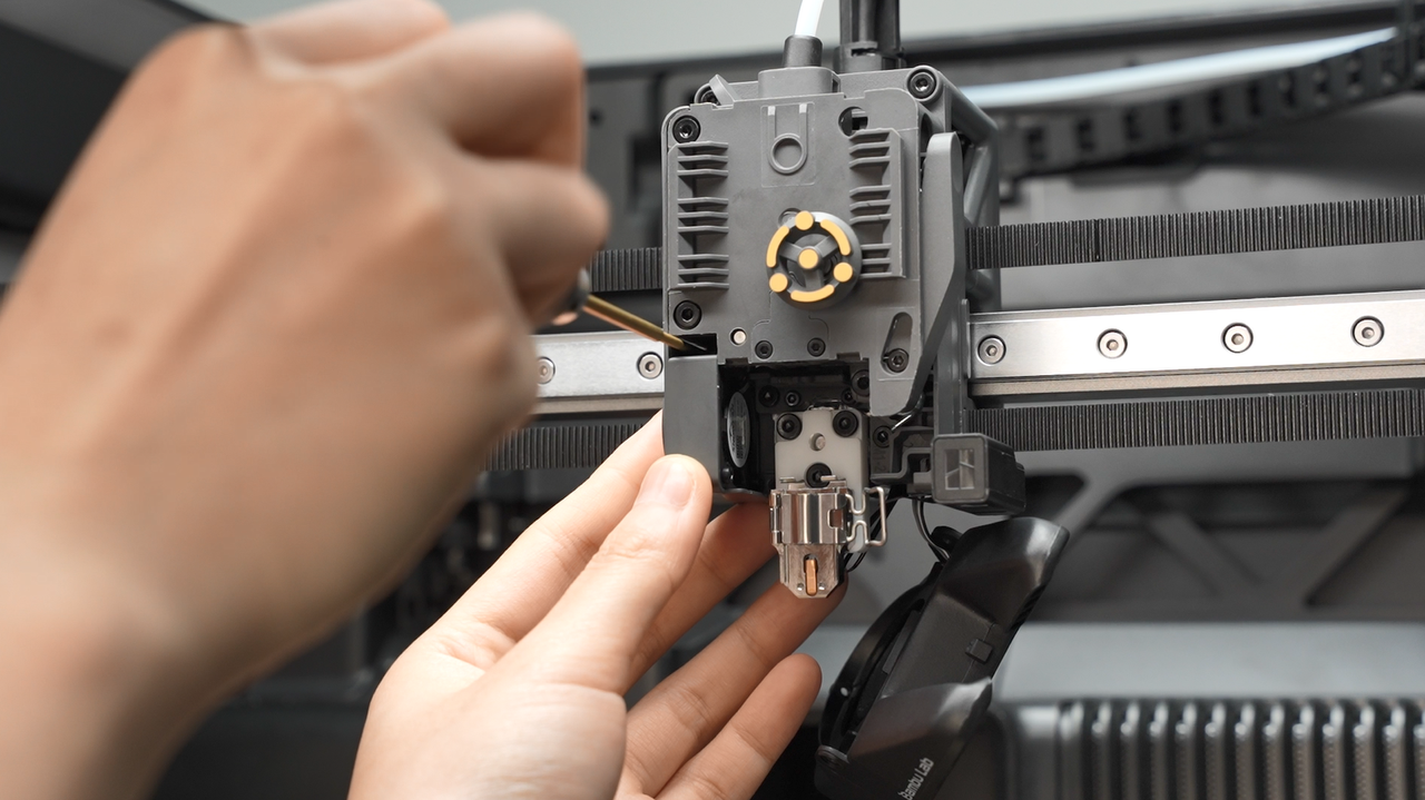
- After opening the interface cover, you can insert your finger, apply gentle force from the inner wall, and push the rear cover of the tool head backward.
 |
 |
|---|
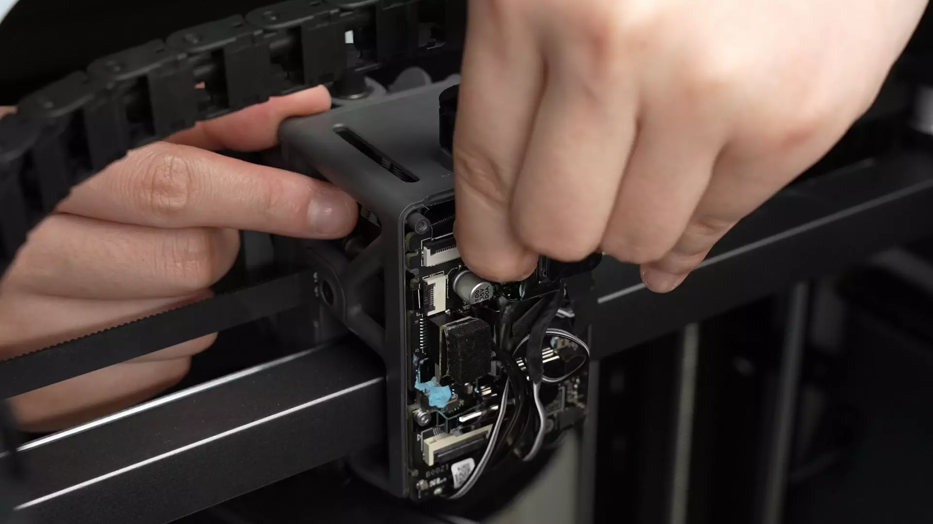
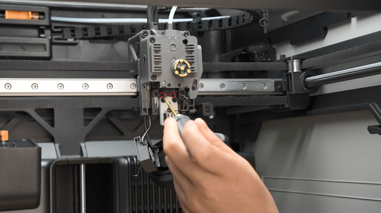
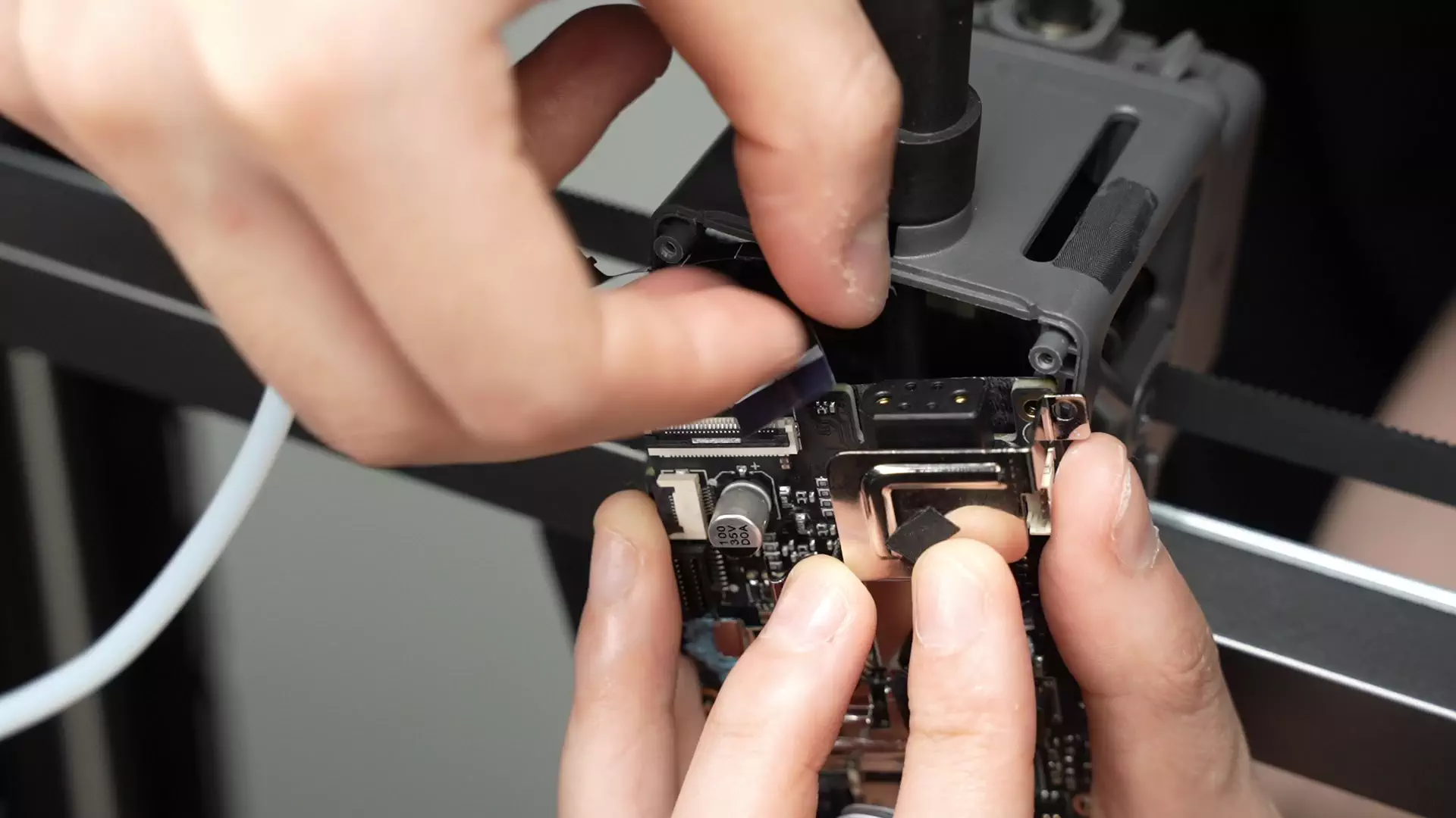
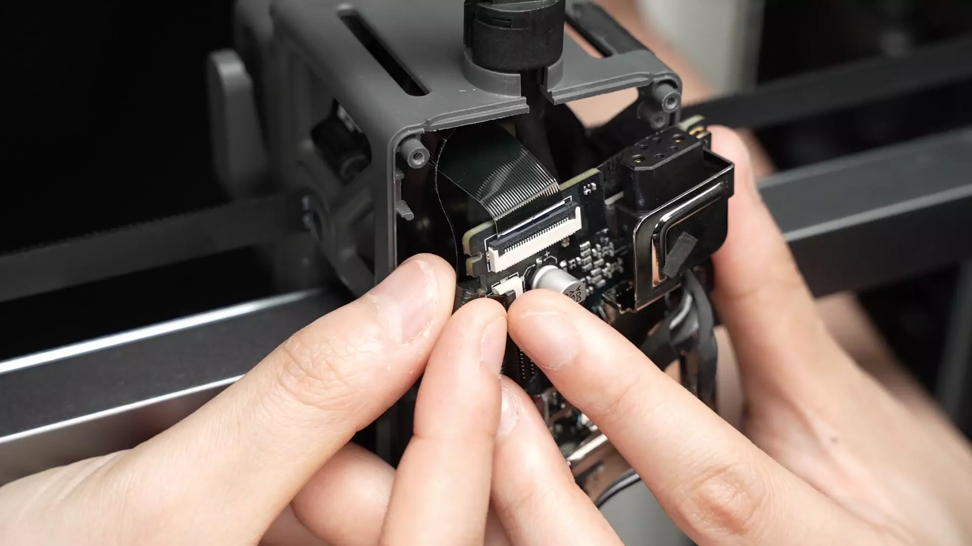
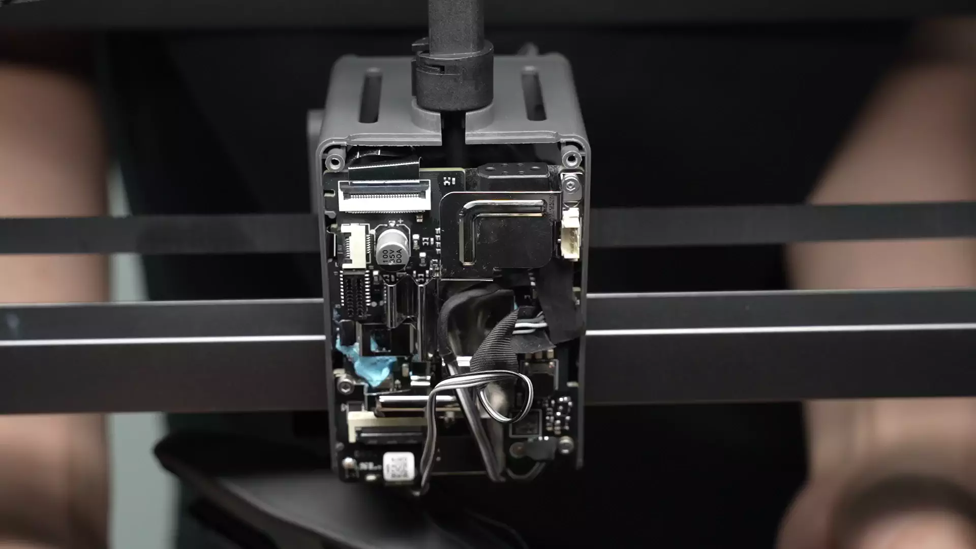
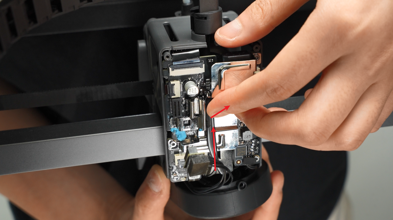
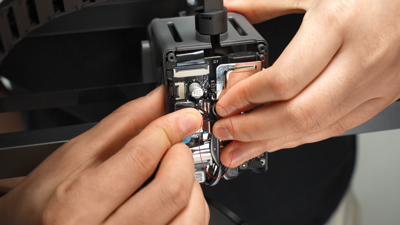
¶ Step 3: Disconnect the connector on the TH board
Disconnect the extruder motor plug, hotend heating assembly cable, and tool head camera plug on the TH board in sequence
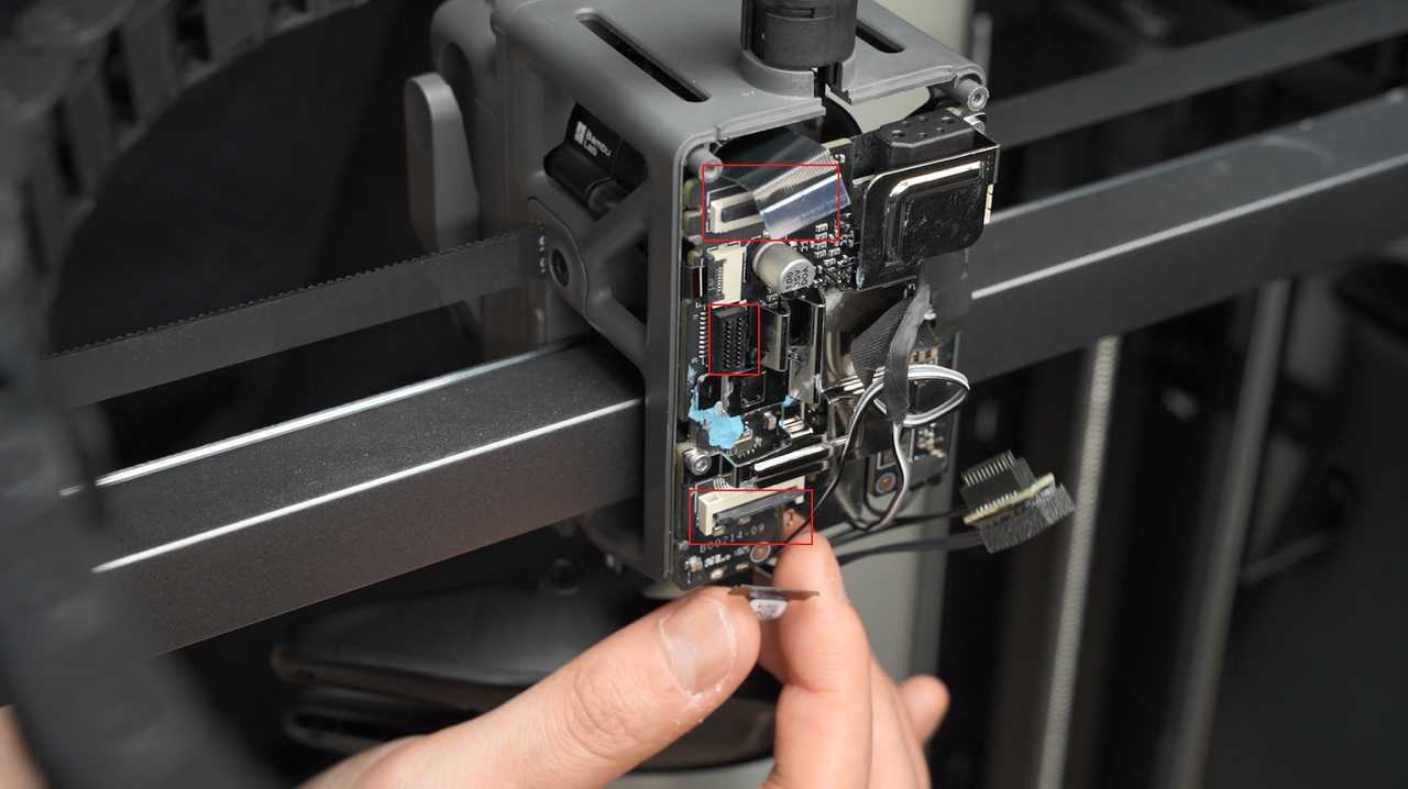
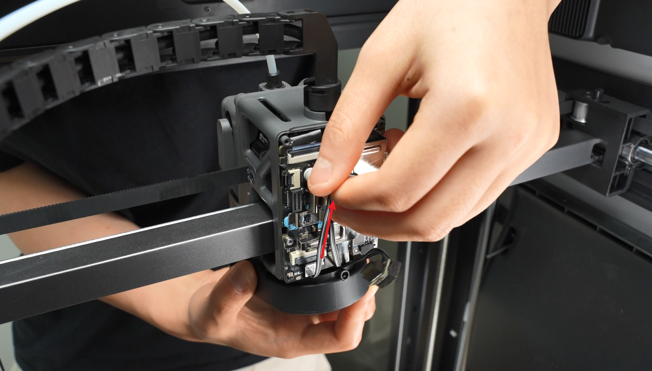
Unscrew the 3 screws on the TH board;
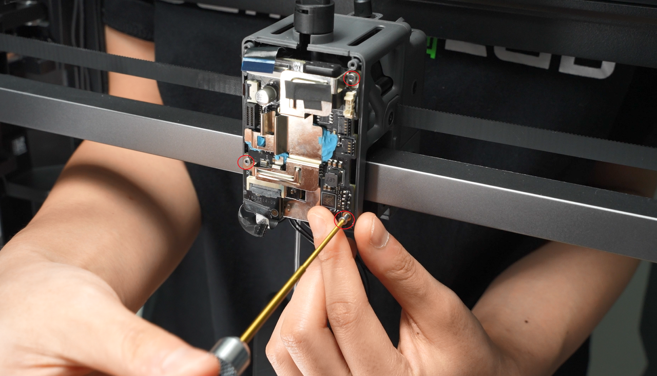
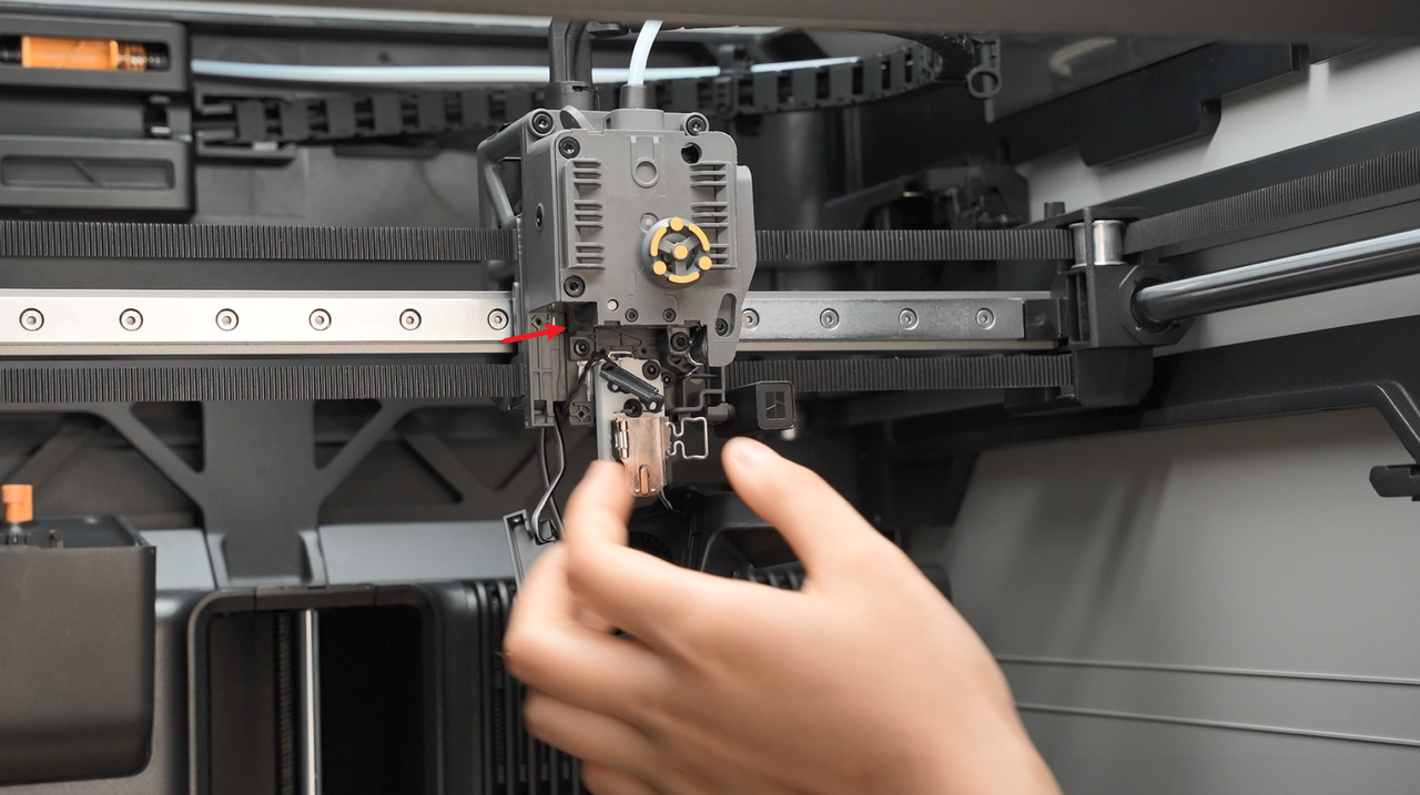
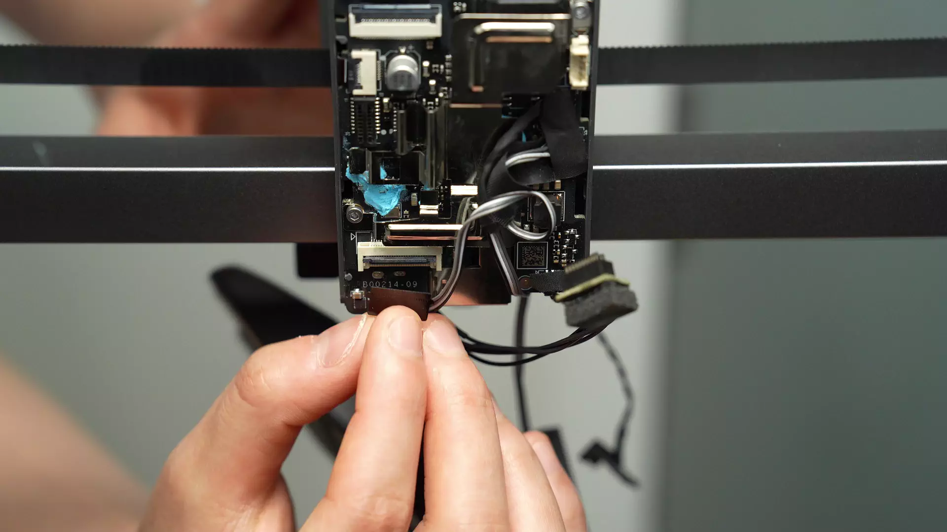
Carefully move the TH board (with fingers against the heatsink to prevent it from falling off), create enough space to disconnect the extruder filament sensor plug, and then disconnect the plug.
¶ Step 4: Remove the hot end
Refer to this tutorial to remove the hot end (click here to jump)
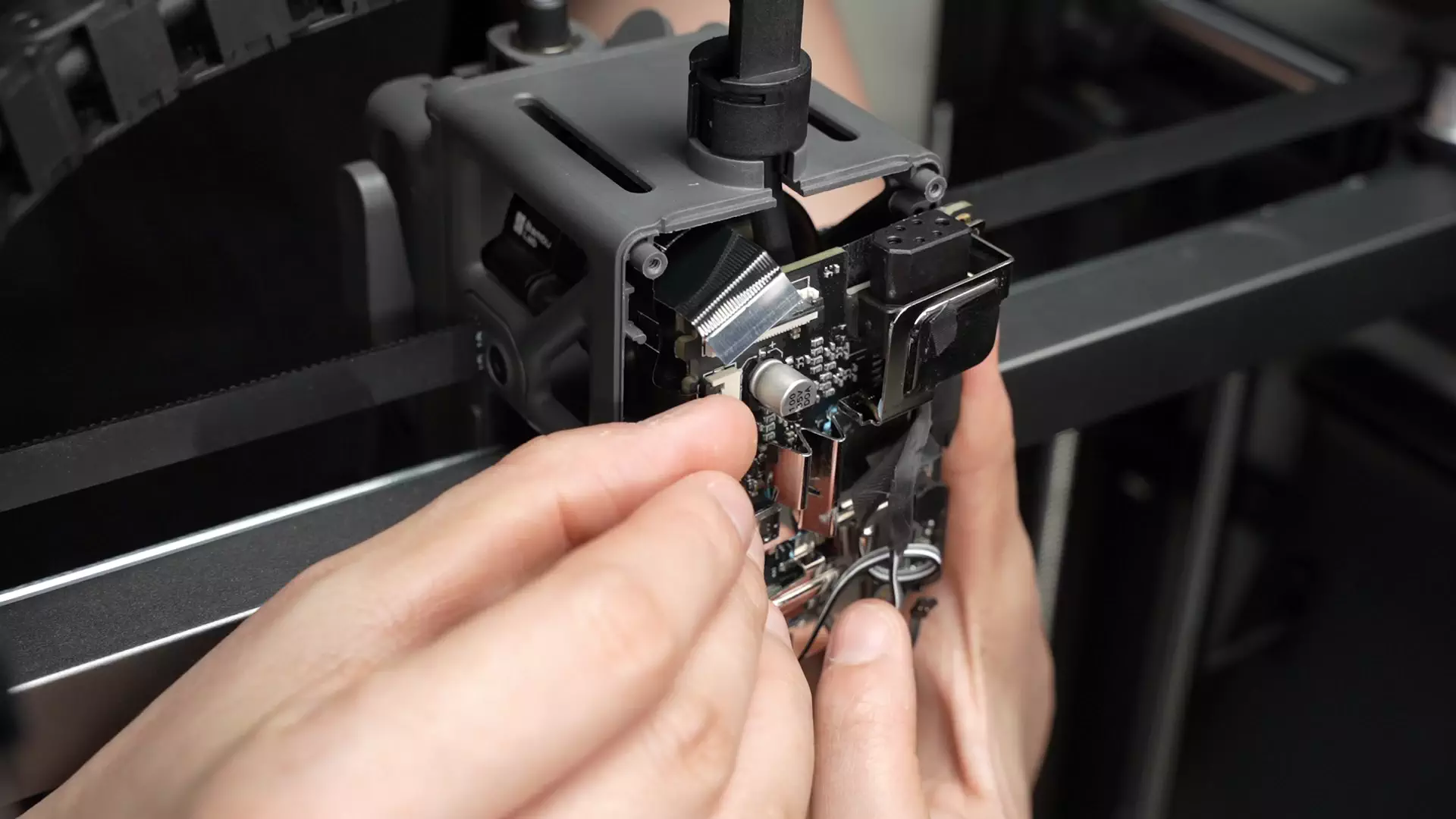
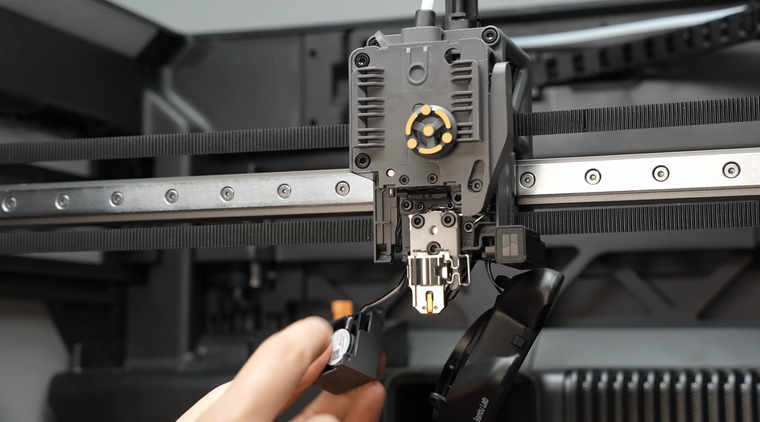
¶ Step 5: Remove the hotend fan and eddy current coil
-
Please note: This step allows you to keep the plugs of the hot end fan and eddy current coil on the TH board connected, and only loosen the screws of the hot end fan and eddy current coil to pull out the cables stuck on the extruder assembly.
-
Remove the two screws of the hotend fan and remove the hotend fan;
 |
 |
|---|
 |
 |
|---|
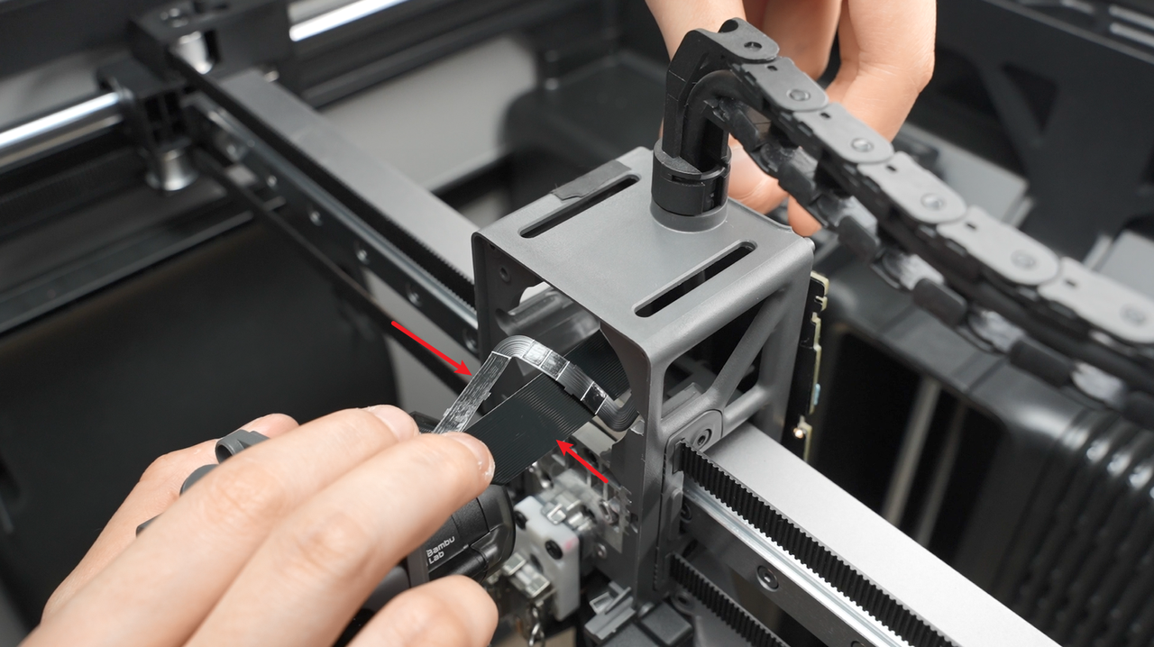
¶ Step 6: Remove the extruder assembly
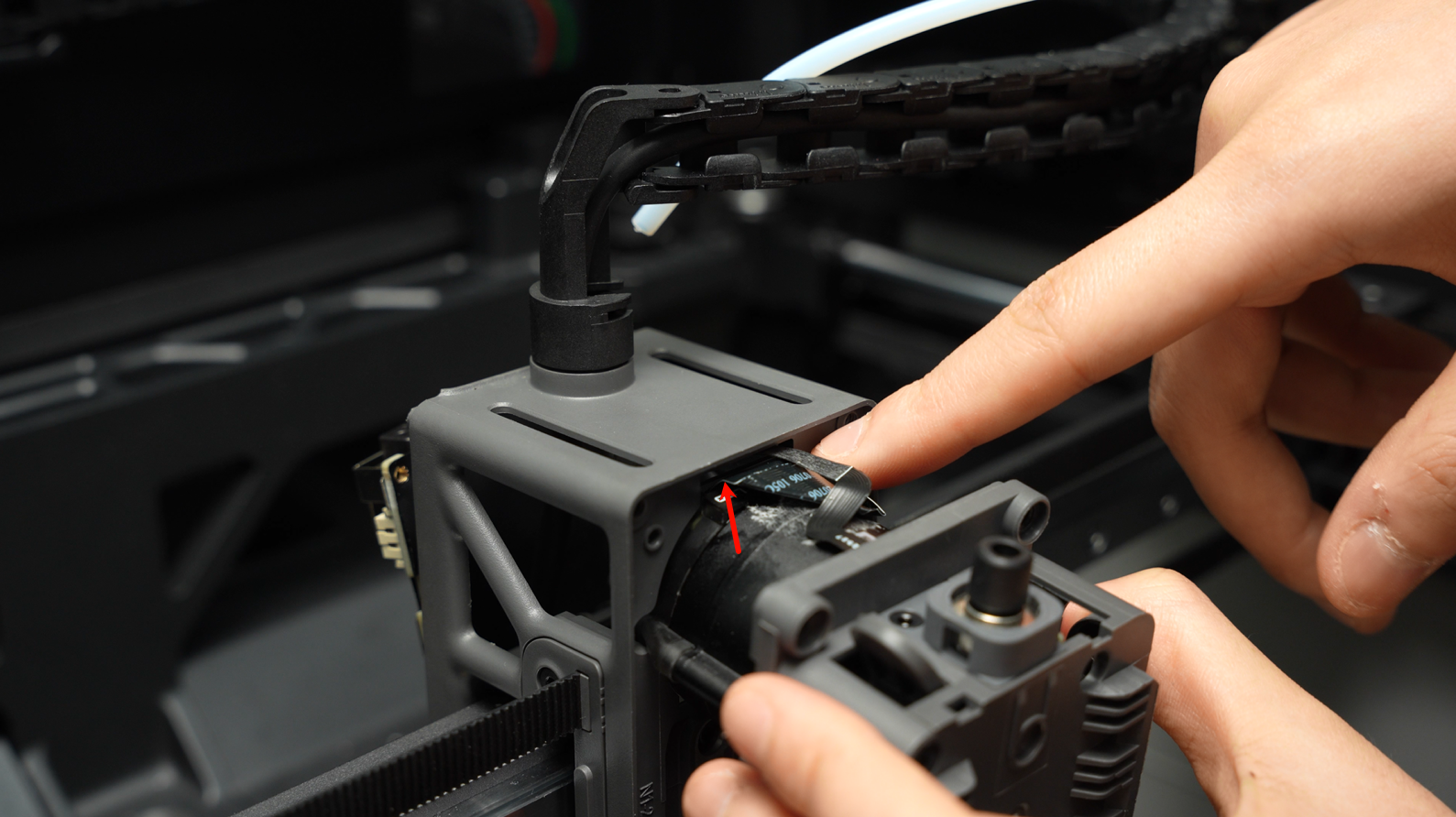
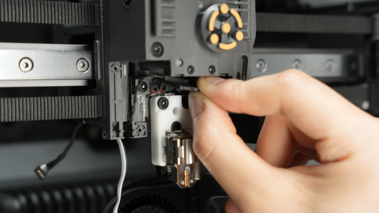
Due to the tape backing on the ribbon cable of the extruder filament sensor and its 90-degree bend, special care must be taken when removing the extruder assembly to avoid tearing the ribbon cable.
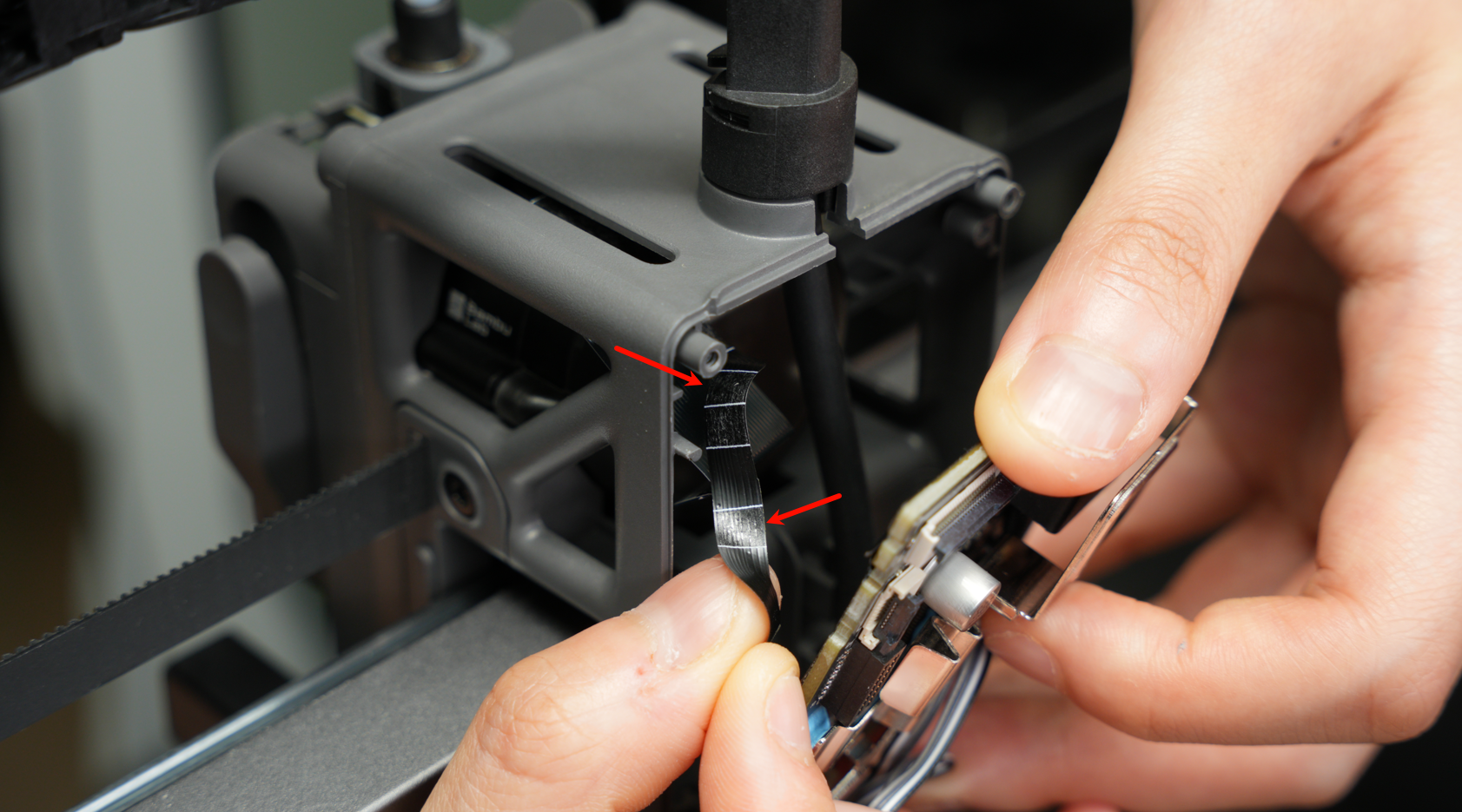
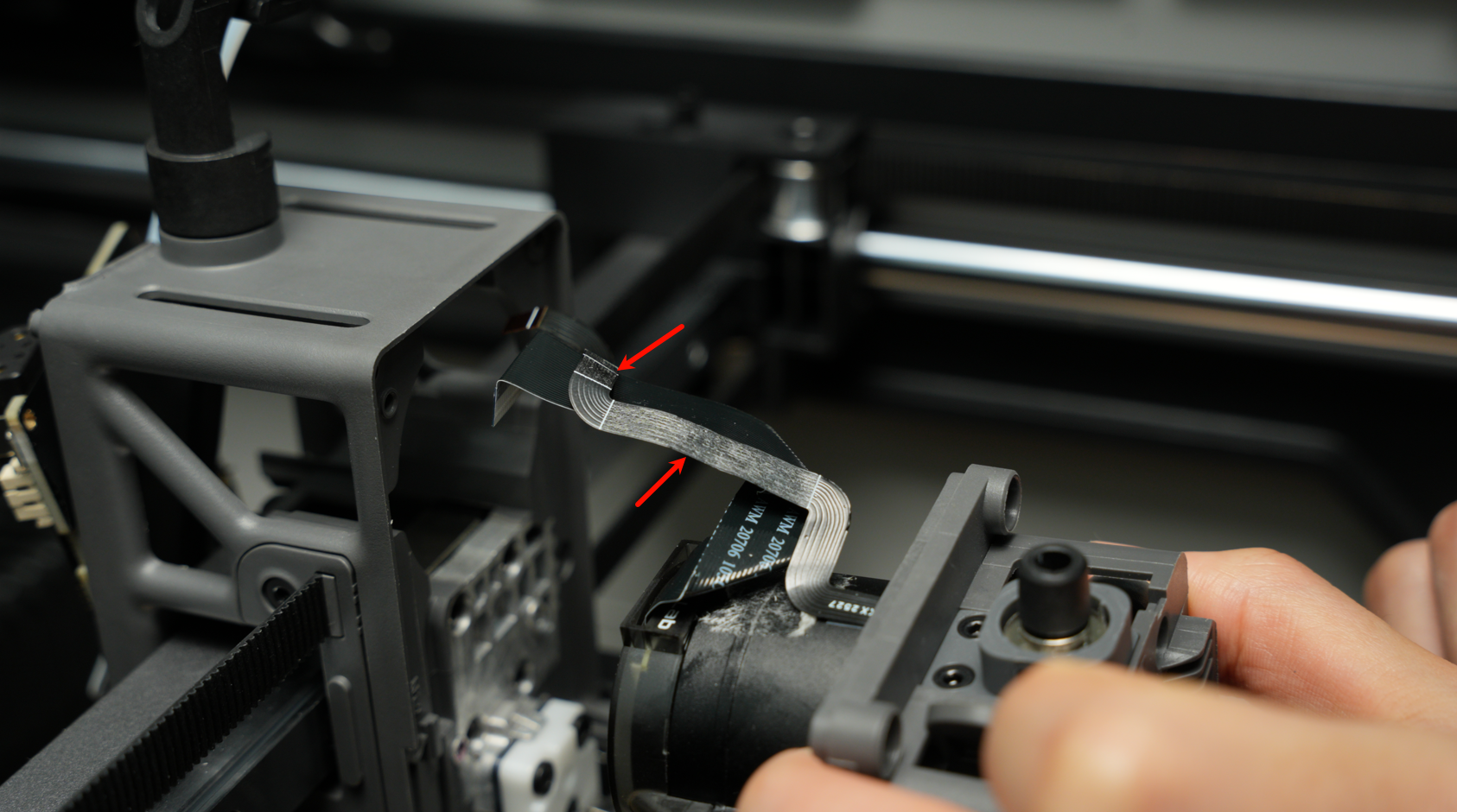
Tear the tape backing of the ribbon cable in the opposite direction of the middle frame.
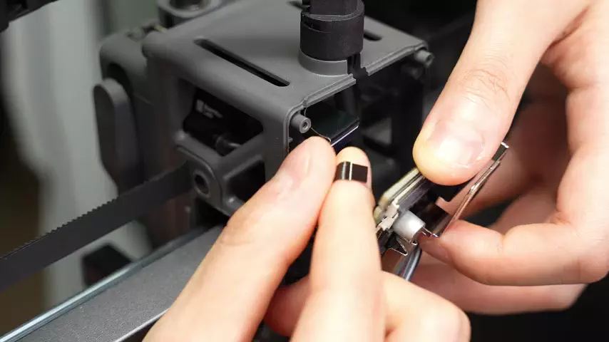
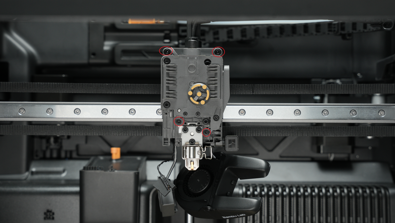
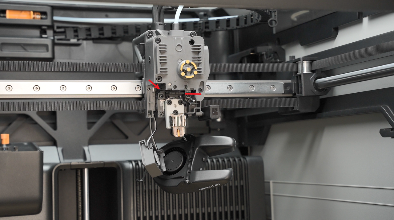
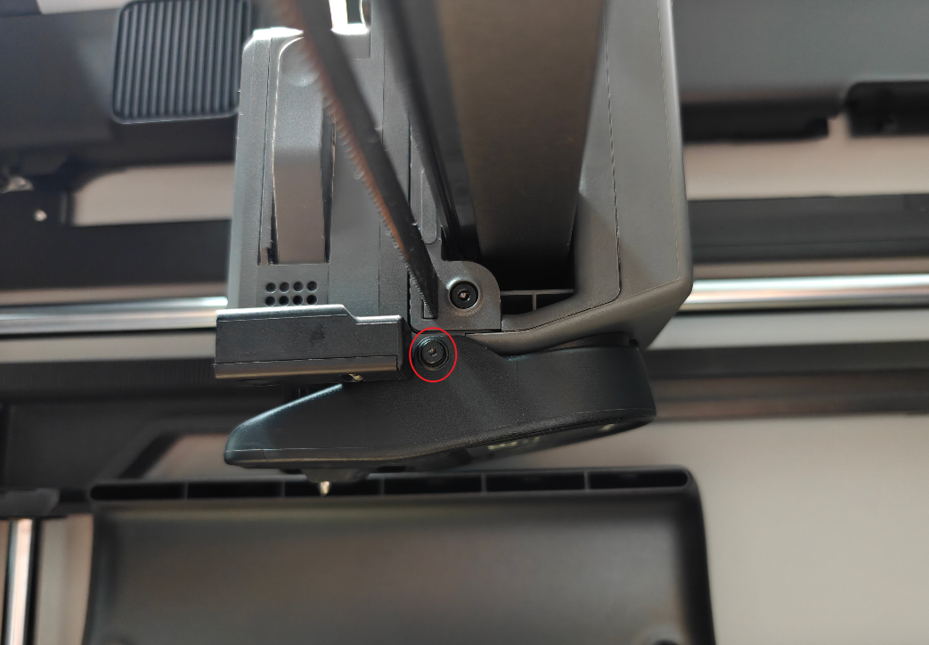
Remove the four extruder screws shown in the illustration

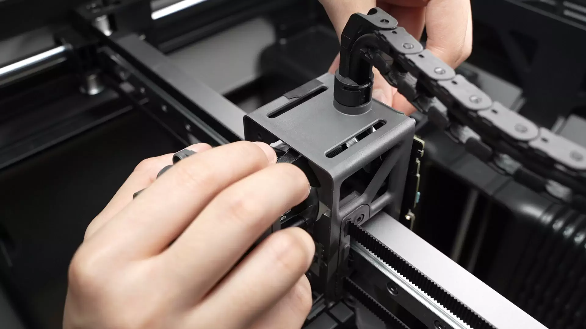
If the backside extruder filament sensor cable is stuck to the plastic middle frame, you can first move the cable to separate it from the middle frame. If the top motor cable interferes, you can use a plastic tool to press it down.
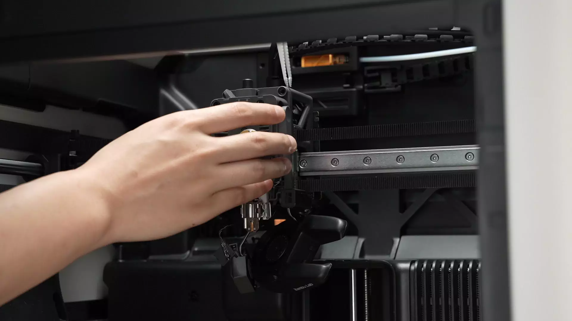
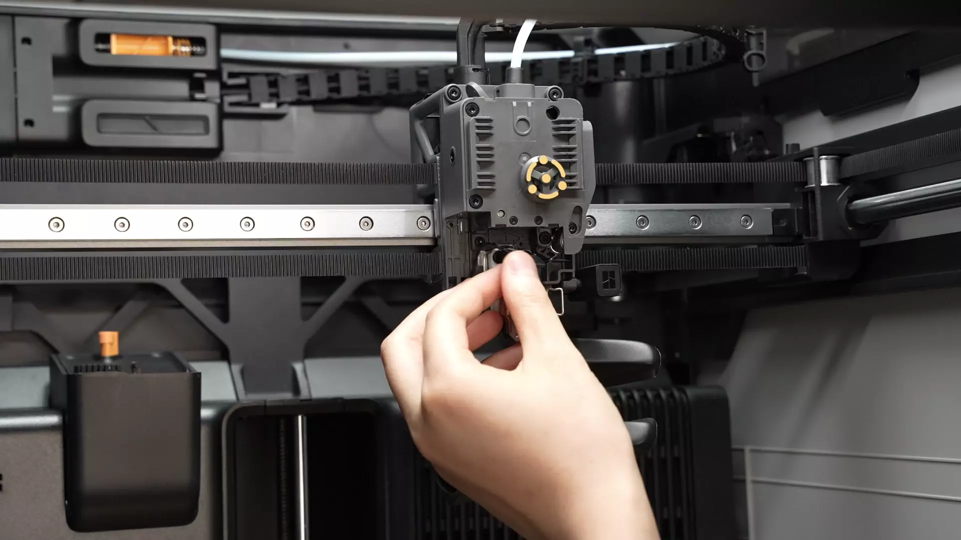
Shake the extruder left and right, and pull out the extruder assembly from the front.
If the ribbon cable of the extruder filament sensor or the motor cable interferes, press down gently with your fingers or a plastic tool; do not pull forcefully.
¶ Install the extruder assembly
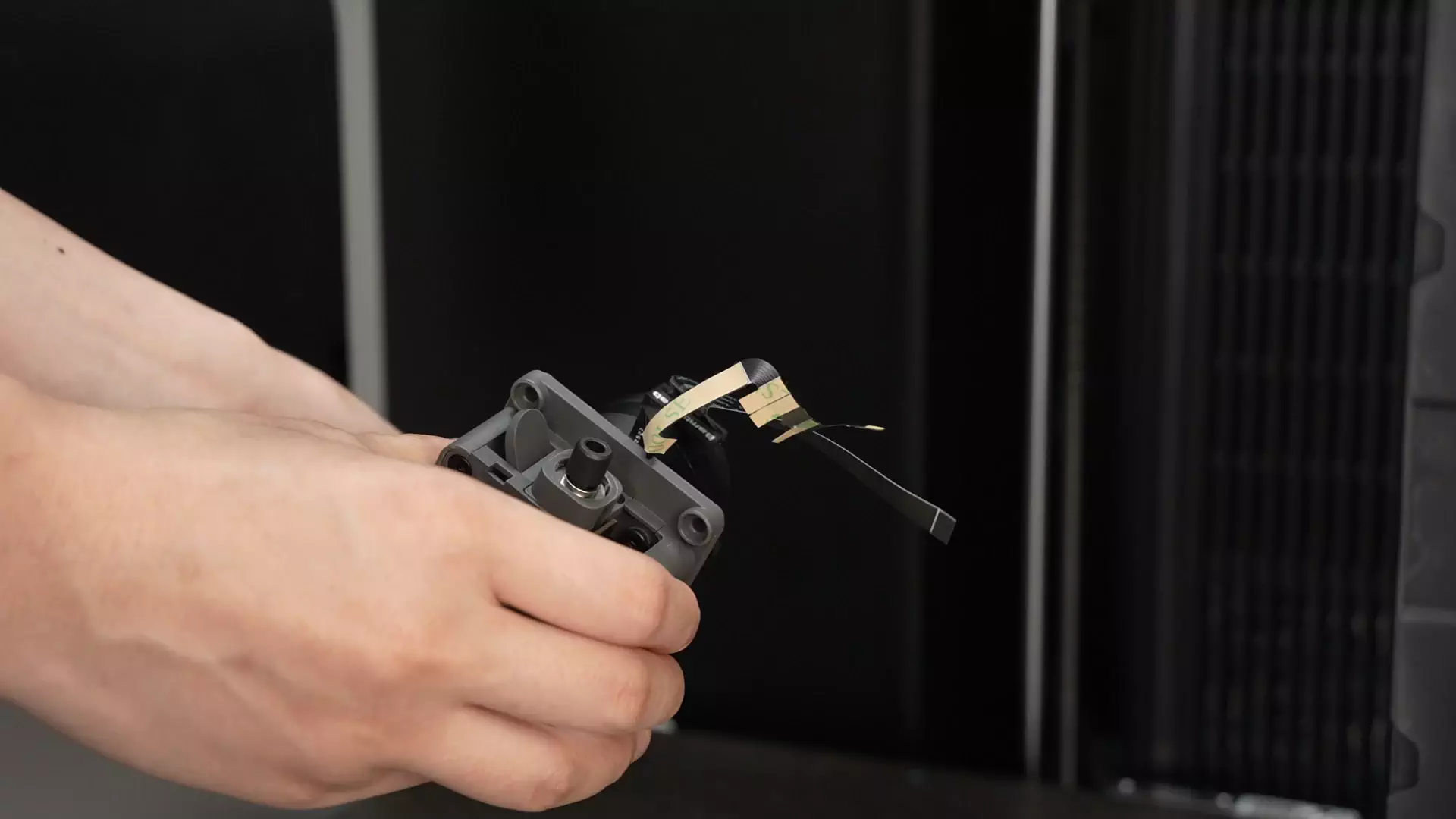
¶ Step 1: Install the new extruder assembly
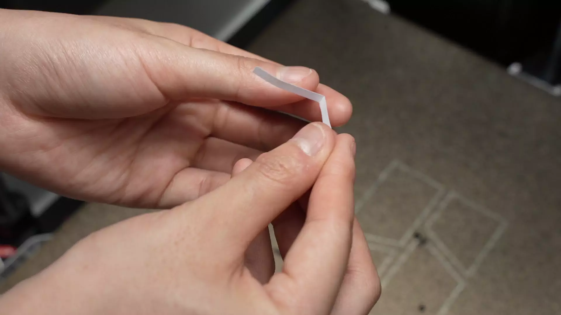
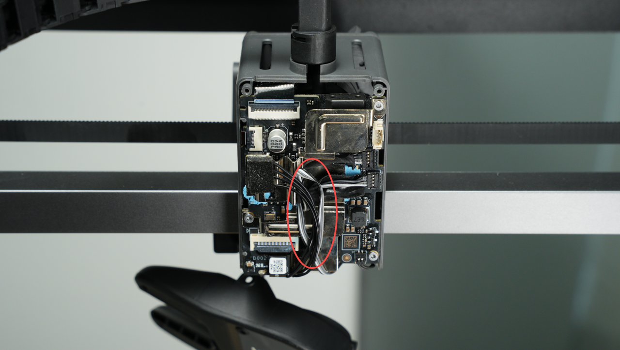
As shown in the animated image, fold the cable harness of the new extruder assembly (you can also refer to the fold marks on the removed old extruder assembly), and tear off the adhesive backing protective film
With the extruder filament sensor cable on top and the extruder motor cable on the bottom, insert the extruder assembly into the middle frame of the tool head.
If the cable is lifted here, use a plastic tool to flatten it before continuing to push it forward to prevent damage to the cable.
4 screws locking the extruder assembly
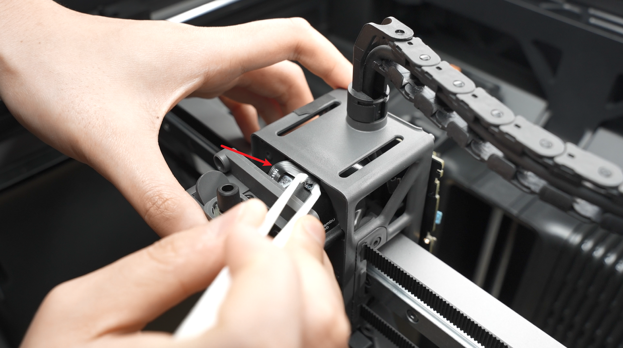
¶ Step 2: Install the eddy current coil and hotend fan
Align the screw holes, ensure the arcs of the two structural components coincide with each other, and lock in the eddy current coil screws. When locking the screws, please pre-lock one first, then tighten the other, and finally tighten the first screw again to ensure that the eddy current coil is in a horizontal state after installation (important).
 |
 |
|---|
Calibrate the installation position of the eddy current coil (important): Reinstall the hot end, fold a properly sized A4 paper in half, insert it into the gap between the hot end and the eddy current coil, and when pulling it back and forth, you can feel a certain frictional resistance, but the paper can still move freely. In this case, the approximate gap between the hot end and the eddy current coil is 0.2-0.3mm.
- Align the labeled side of the fan towards the hot end and align it with the screw holes (refer to the red and yellow circles in the figure below);
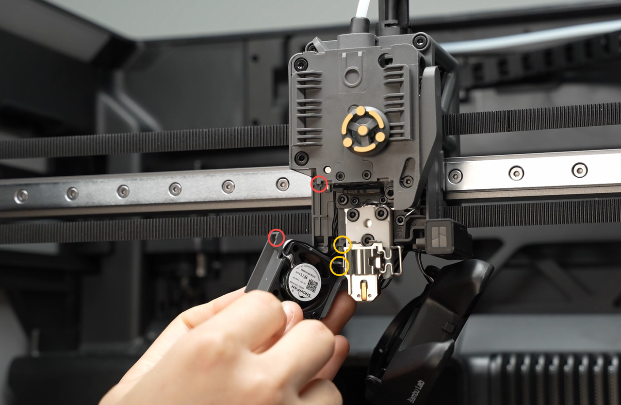
Fold the fan cable into the groove shown in the diagram, then install the fan.
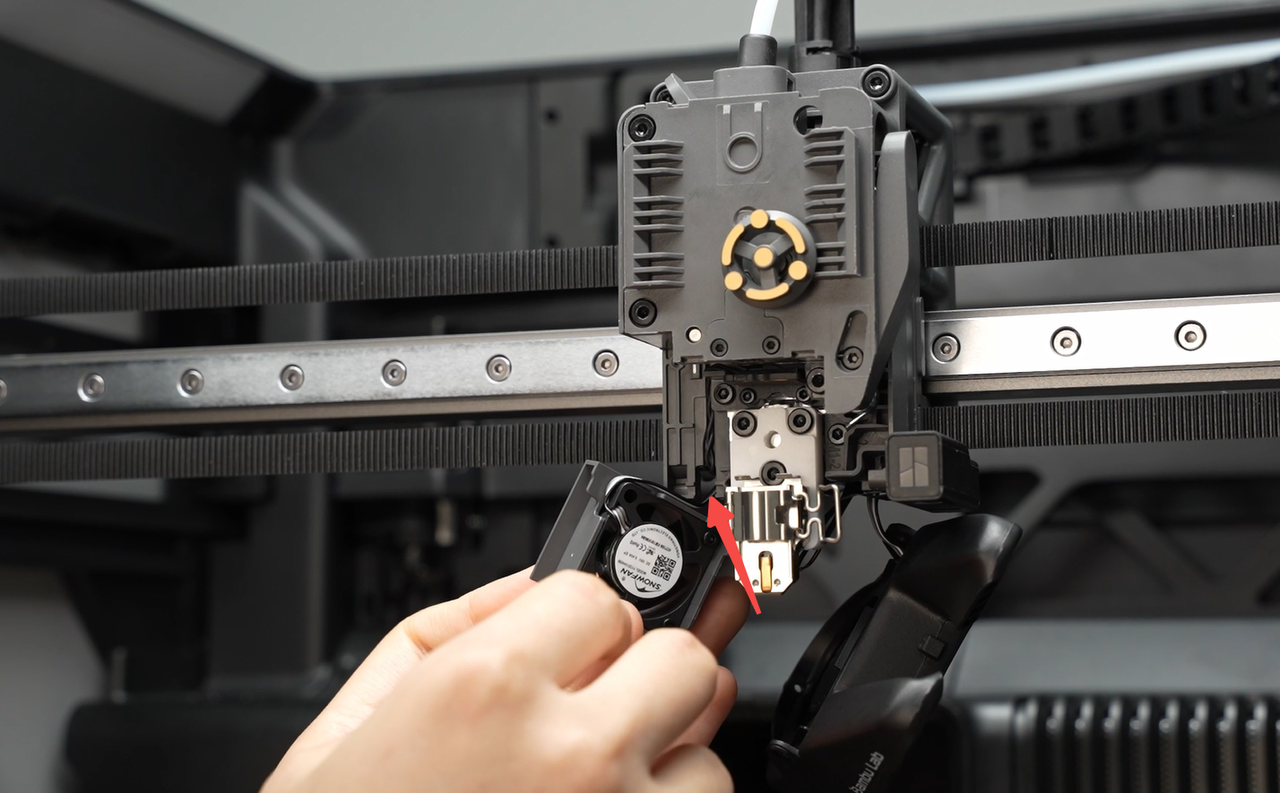
- Tighten the two screws securing the fan.

¶ Step 3: Install the hot end
Refer to this tutorial to install the hot end (click here to jump)
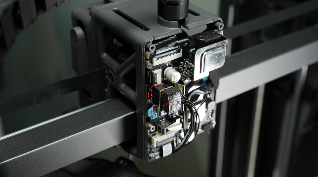
¶ Step 4: Connect the connector on the TH board
- Connect the plug of the extruder motor
- Connect the extruder filament sensor plug, press the cable against the plastic middle frame to make it adhere to the middle frame.
Screw back the 3 screws of the TH board.

Insert the toolhead camera plug
- Pre-align the screw holes of the fan, arrange the fan cable on the TH, pull it upward, and fold the excess cable to prevent it from being crushed by the fan housing or the tool head rear cover, which could cause fan malfunction.
 |
 |
|---|
After tidying up the cables, insert the hot end heating assembly plug, and use the hot end heating assembly plug and cables to hold down the component cooling fan cable.
 |
 |
|---|
When inserting the hot end heating assembly, ensure alignment with the holes and avoid misalignment.
¶ Step 4: Install the rear cover of the tool head
- Install the rear cover of the tool head;
- After installation, pay attention to check whether the cable of the component cooling fan is located in the dedicated notch to avoid being squeezed by the rear cover frame;
 |
 |
|---|
- Lock in 2 rear cover fixing screws.
¶ Step 5: Install the component cooling fan
- Align with the screw holes and install the component cooling fan; when inserting the fan, be careful not to press on the fan cable.
If the cable is too long, you need to return to Step 1 of the installation guide and first fold the excess cable.
- Lock in 3 screws to secure the component cooling fan.
 |
 |
|---|
¶ Function Verification
To ensure everything is functioning correctly, please turn on the printer and perform the filament load and unload operations. If everything works smoothly, it indicates that the replacement was successful.
¶ Calibration steps after operation
We recommend that you perform a comprehensive calibration after replacing the extruder unit to ensure the smooth operation of the printer.
Additionally, it is highly recommended to clean the textured PEI print bed before printing, as the build plate may have been contaminated during the process of replacing the extruder unit.
¶ Conclusion
We hope this guide will provide you with useful information to help you solve problems.
To ensure that you operate safely and effectively, if you have any doubts or questions about any steps in the guide, please contact our Client Server team before starting the operation.
We are always happy to answer your questions and provide support.
Click here to contact online technical support (service hours 9:00-21:00)