¶ H2S TH Board
¶ When to Use?
Common issues that may require replacement of the H2S printer's extruder mainboard (abbreviated as TH board) include:
-
Damage to the filament sensor board connector
-
Damage to the hotend heating assembly and NTC sensor circuit
-
The extruder motor not rotating as expected, possibly due to a stepper motor driver failure
-
Recommendation for replacement by Bambu Lab technical support
¶ Tools and Materials
-
New TH board
-
H1.5 Allen key
-
30 minutes
¶ Screw List
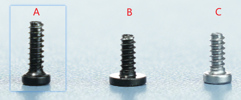
-
Screw A: 3 screws in total (shared with the rear cover) for the back of the part cooling fan and the toolhead rear cover: BT2x6.5
-
Screw B: 2 screws in total for the left and right sides of the part cooling fan: BT2x5
-
Screw C: 3 screws in total for the TH board: BT2x5
¶ Safety Warning
IMPORTANT!
It's crucial to power off the printer before conducting any maintenance work, including work on the printer's electronics and tool head wires. Performing tasks with the printer on can result in a short circuit, leading to electronic damage and safety hazards.
During maintenance or troubleshooting, you may need to disassemble parts, including the hotend. This exposes wires and electrical components that could short circuit if they contact each other, other metal, or electronic components while the printer is still on. This can result in damage to the printer's electronics and additional issues.
Therefore, it's crucial to turn off the printer and disconnect it from the power source before conducting any maintenance. This prevents short circuits or damage to the printer's electronics, ensuring safe and effective maintenance. For any concerns or questions about following this guide, open a new ticket in our Support Page and we will do our best to respond promptly and provide the assistance you need.
¶ Remove the Old TH Board
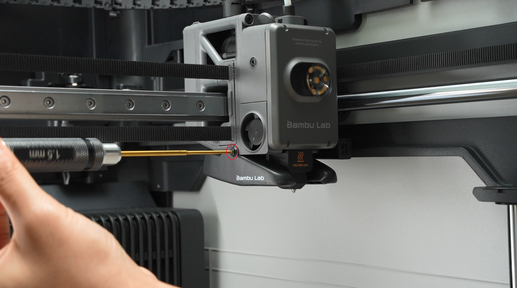
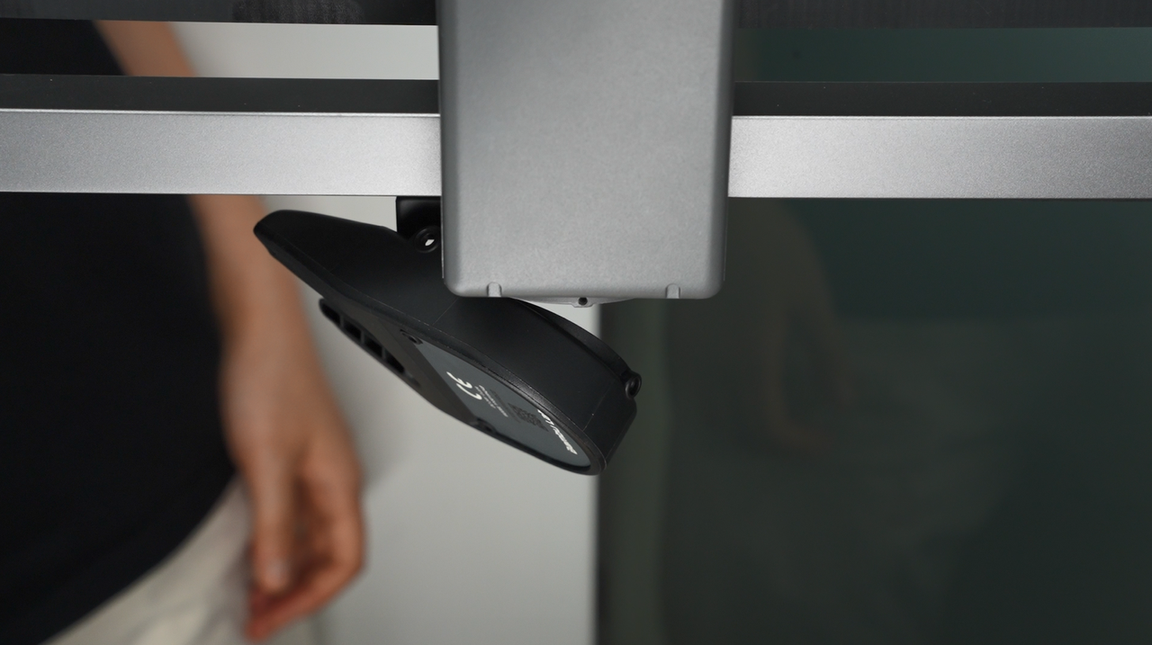
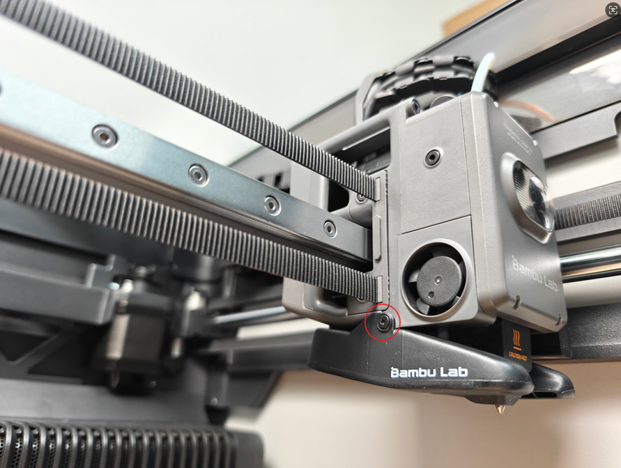
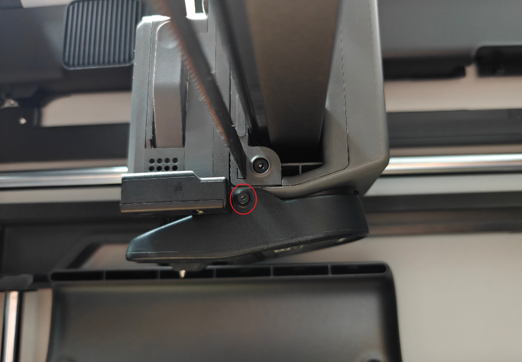
¶ Step 1: Loosen the Part Cooling Fan
Unscrew the 3 screws of the part cooling fan, among which the 1 screw on the back is shared with the toolhead rear cover.
After loosening the screws, do not pull the fan; let it hang naturally to avoid damaging the connector.
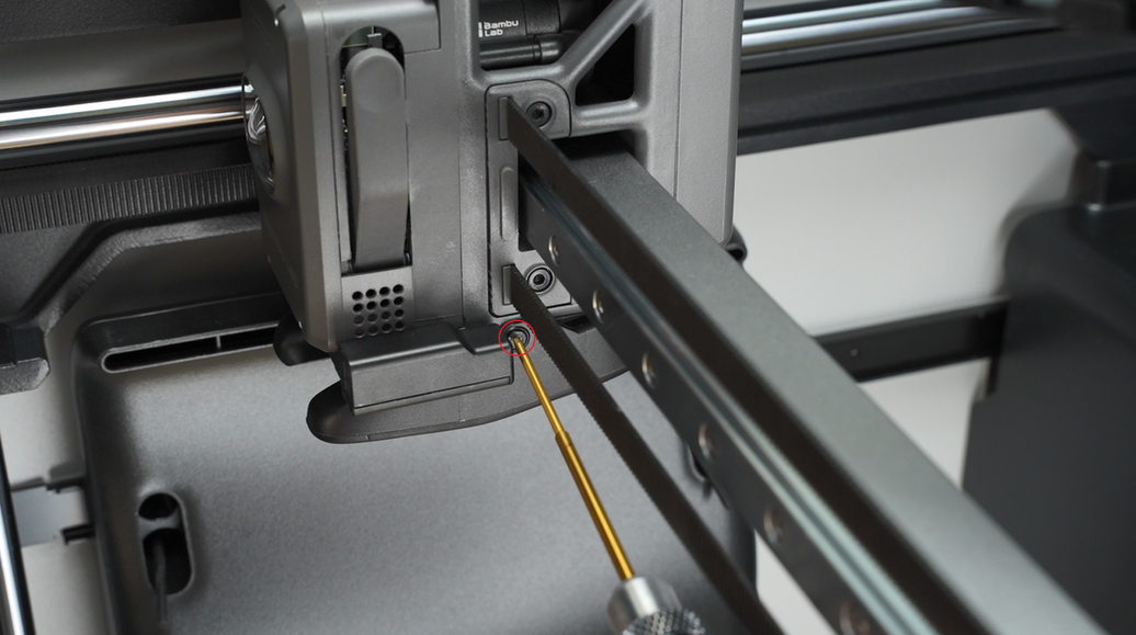
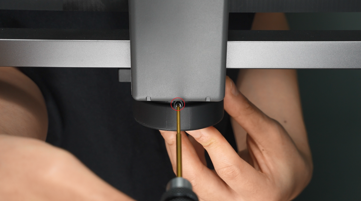
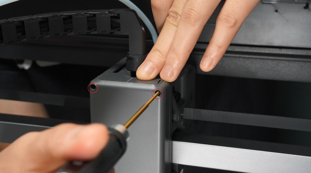
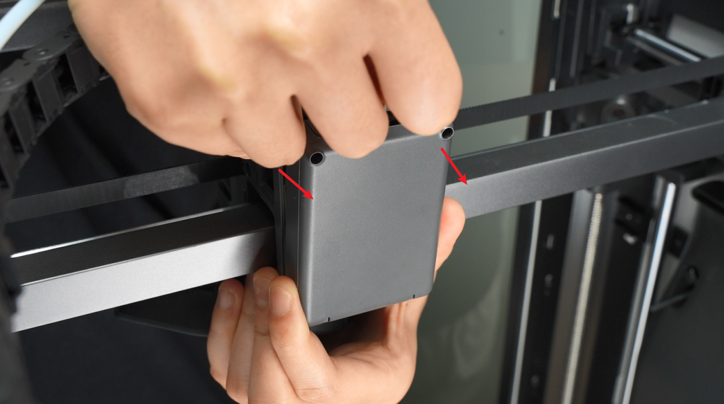
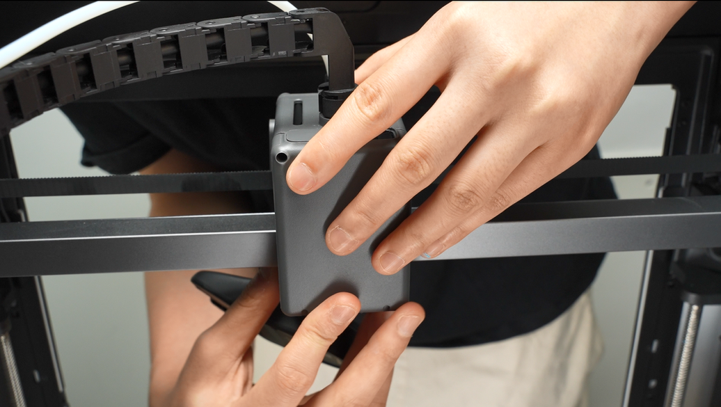
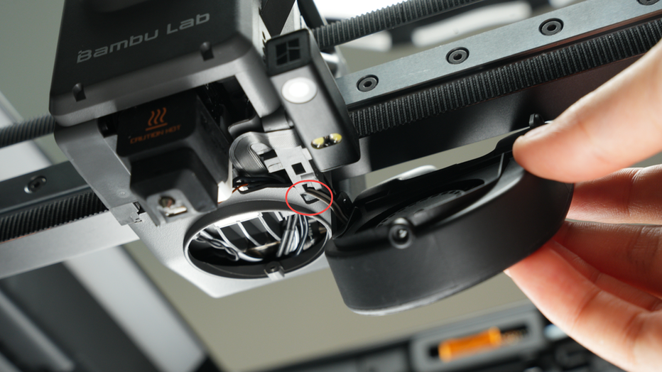
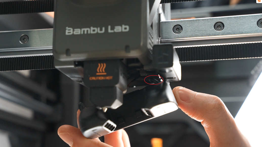
¶ Step 2: Loosen the Toolhead Rear Cover
Remove the 2 screws on the top of the toolhead rear cover and open the module interface cover.
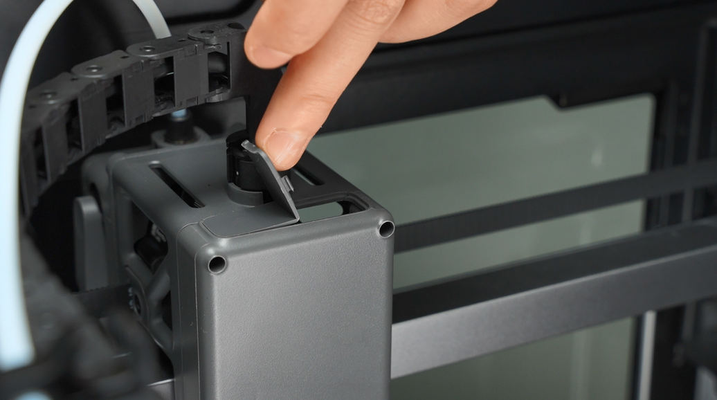
After opening the interface cover, gently push the toolhead rear cover backward with your fingers from the inner wall.
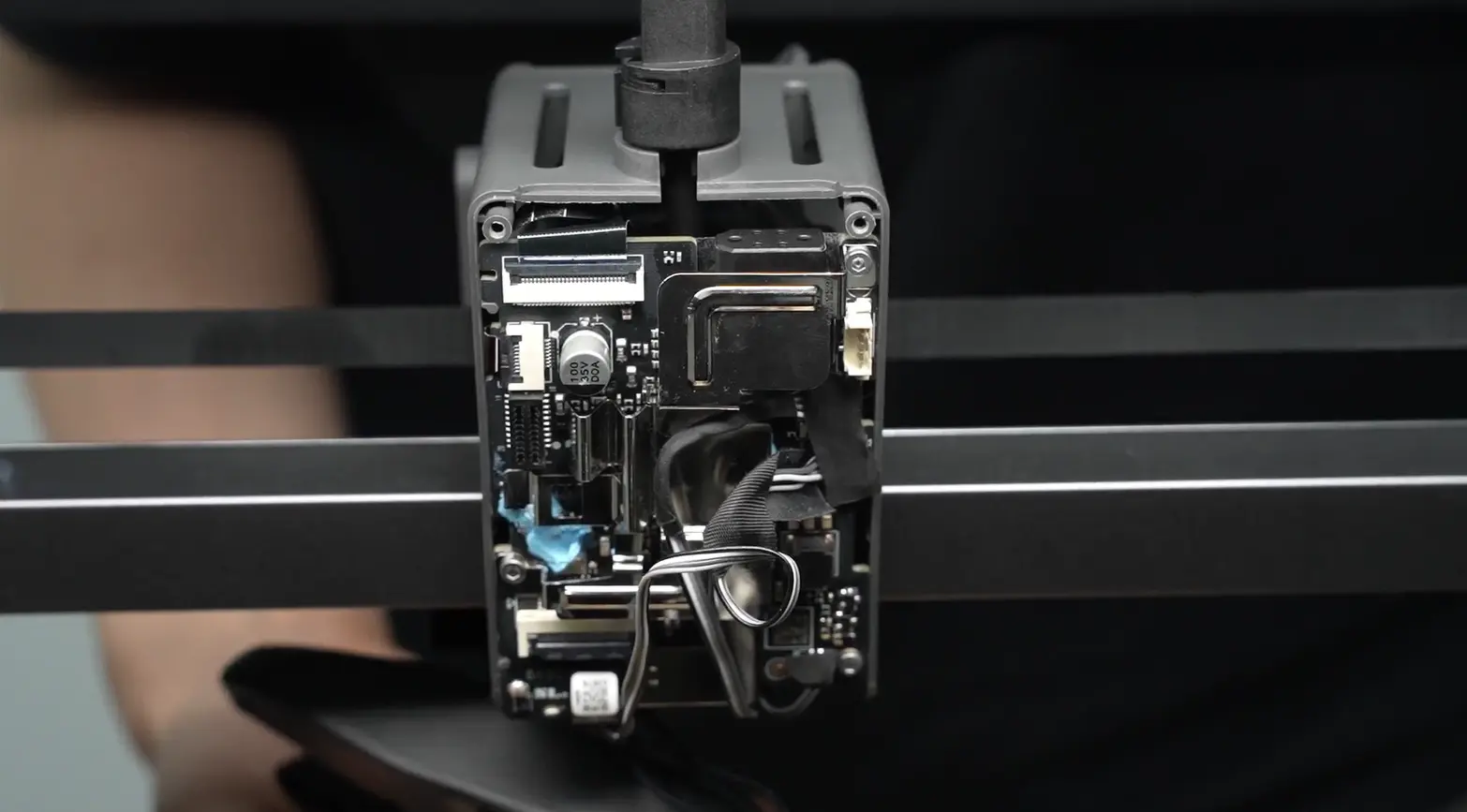
¶ Step 3: Disconnect All Plugs on the TH Board (Except the Filament Hall Plug and USB-C Plug)
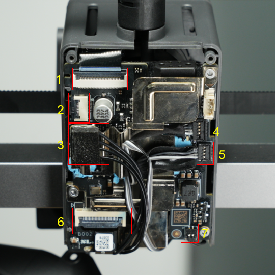
| Serial Number | Component Name | Serial Number | Component Name |
|---|---|---|---|
| 1 | Extruder motor | 2 | Filament sensor assembly |
| 3 | Hotend heating assembly | 4 | Cooling fan for hotend |
| 5 | Part cooling fan | 6 | Toolhead camera |
| 7 | Eddy current coil |
Disconnect the extruder motor plug;
Disconnect the hotend heating assembly plug;
Disconnect the toolhead camera plug;
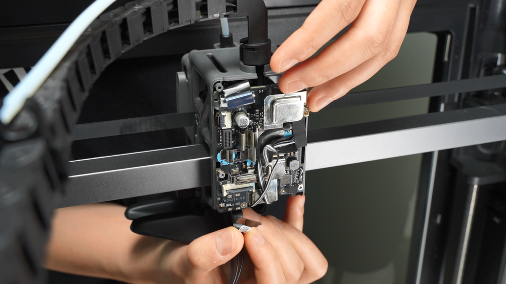
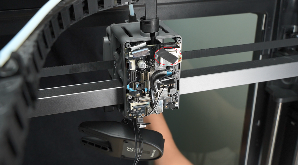
Tear off the acetate tape on the part cooling fan plug and keep it; you will need to reattach it during installation.
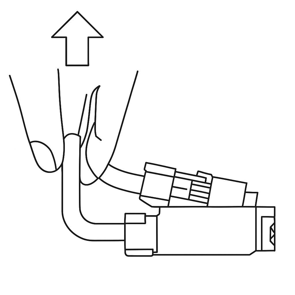
Pinch the base and apply force in the direction perpendicular to the PCB board to disconnect the plugs of part cooling fan and cooling fan for hotend.
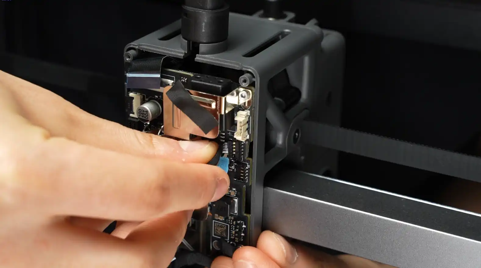
Similarly, tear off the tape of the eddy current sensor, keep it, and disconnect the eddy current sensor plug.
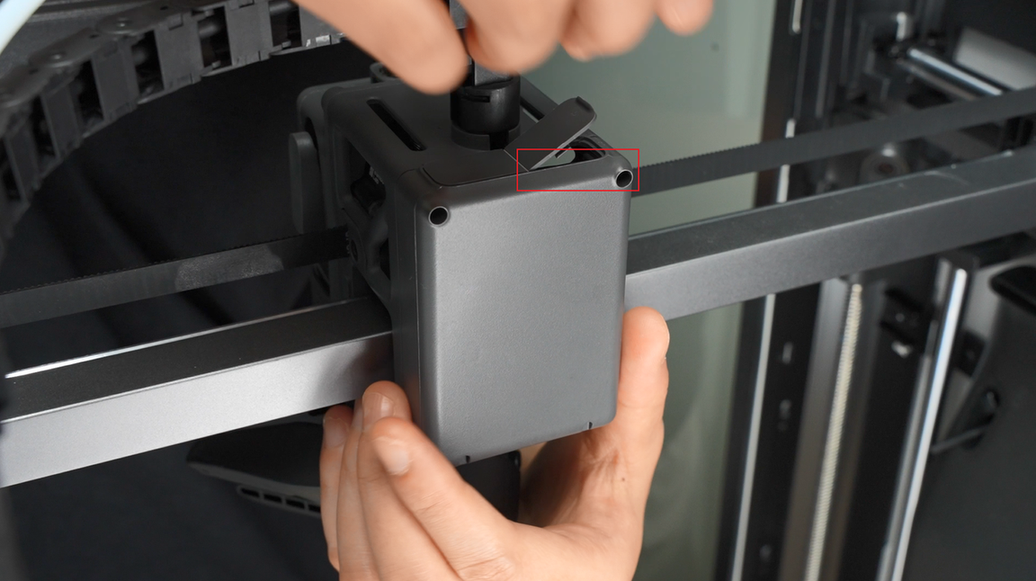
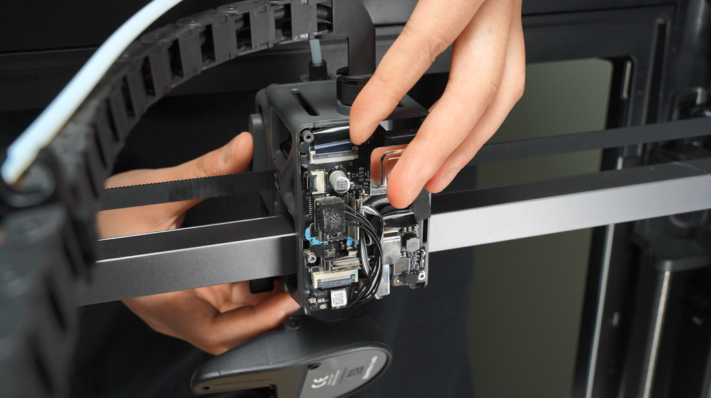
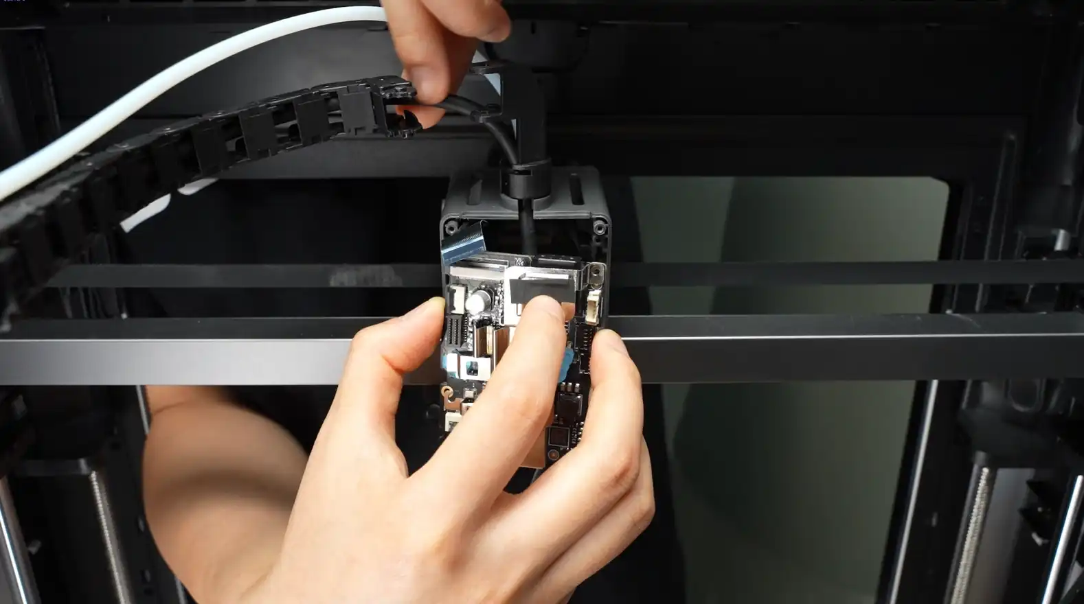
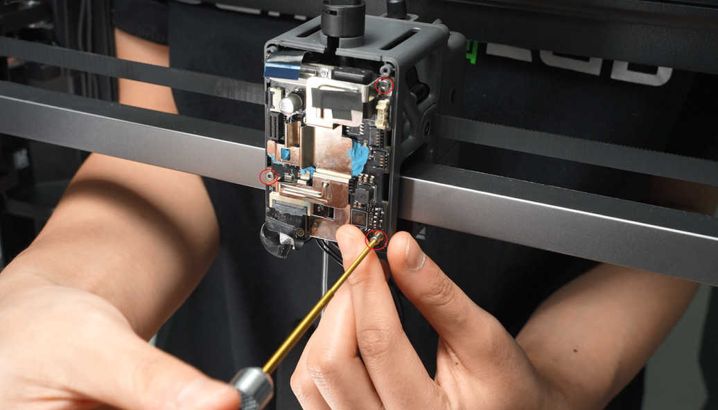
¶ Step 4: Unscrew the 3 Screws on the TH Board
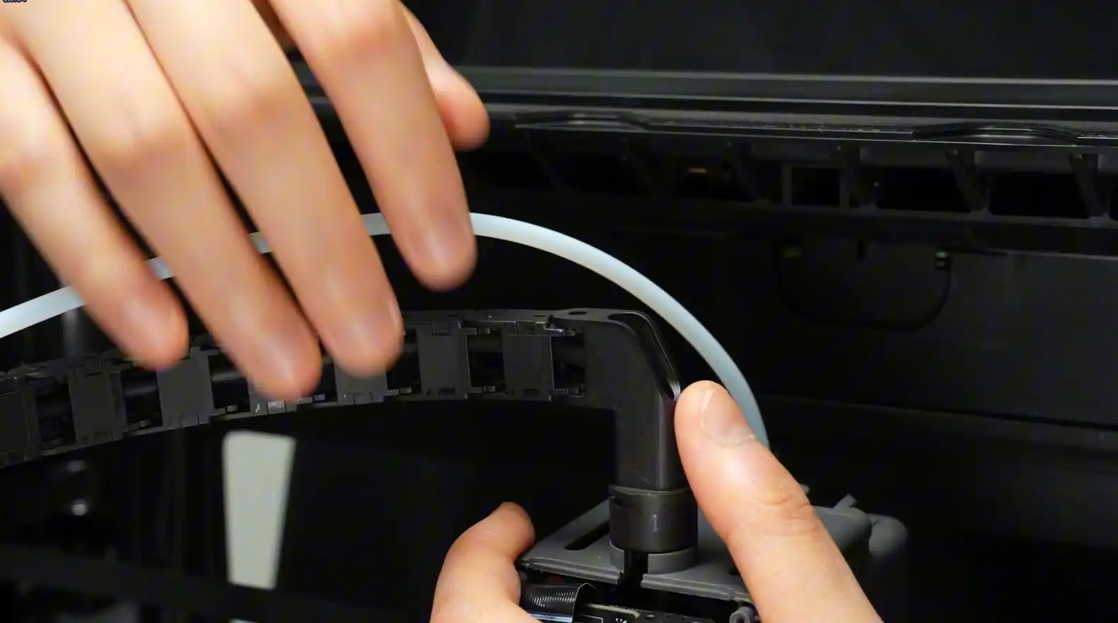
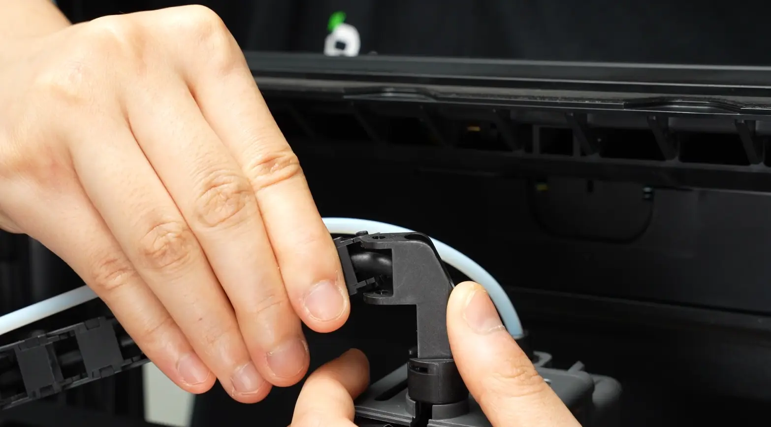
Loosen the section of the cable chain nearest to the bracket on the toolhead.
Unscrew the 3 screws on the TH board;

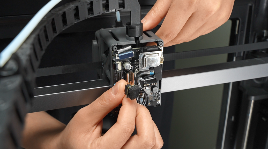
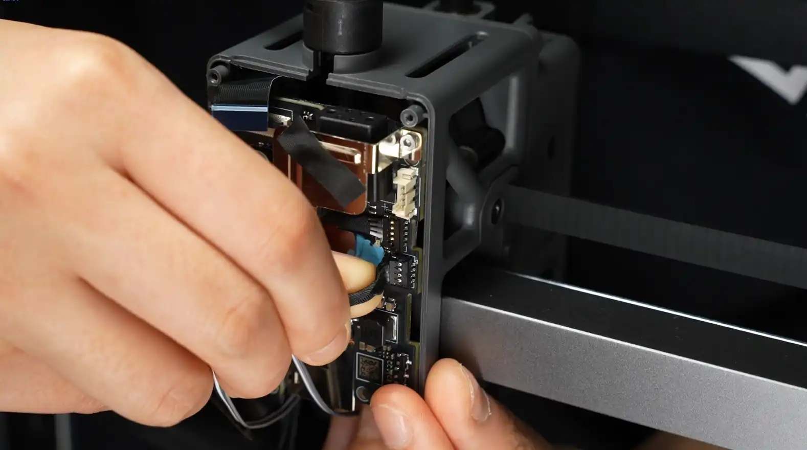
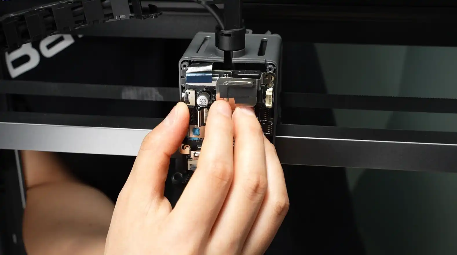
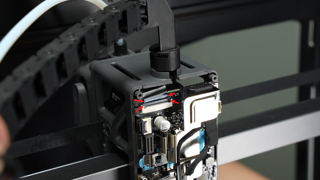
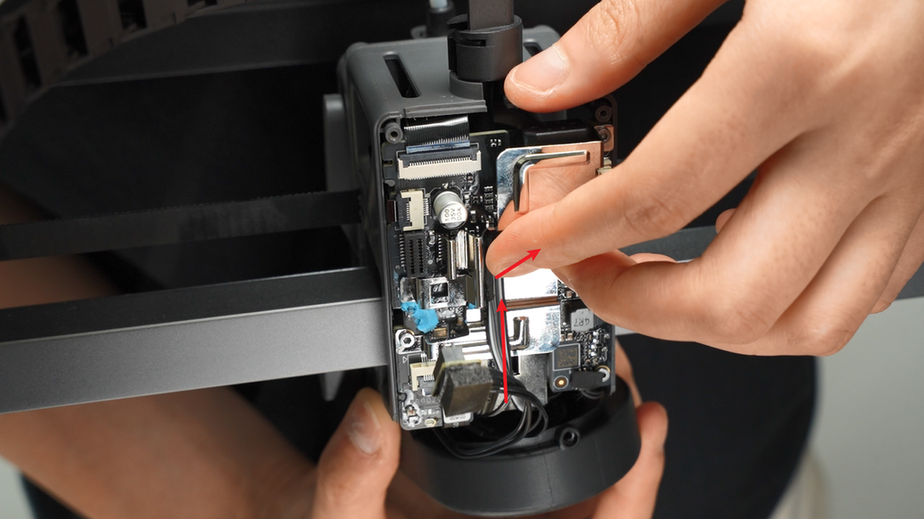
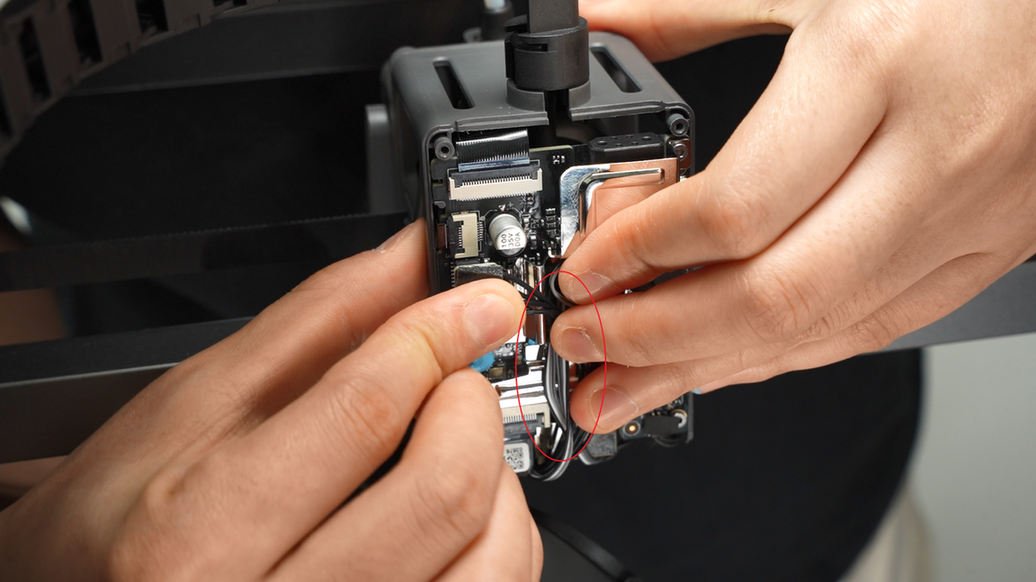
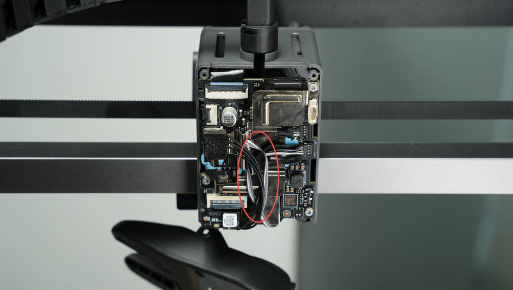
¶ Step 5: Disconnect the Filament Sensor Plug and USB-C Plug
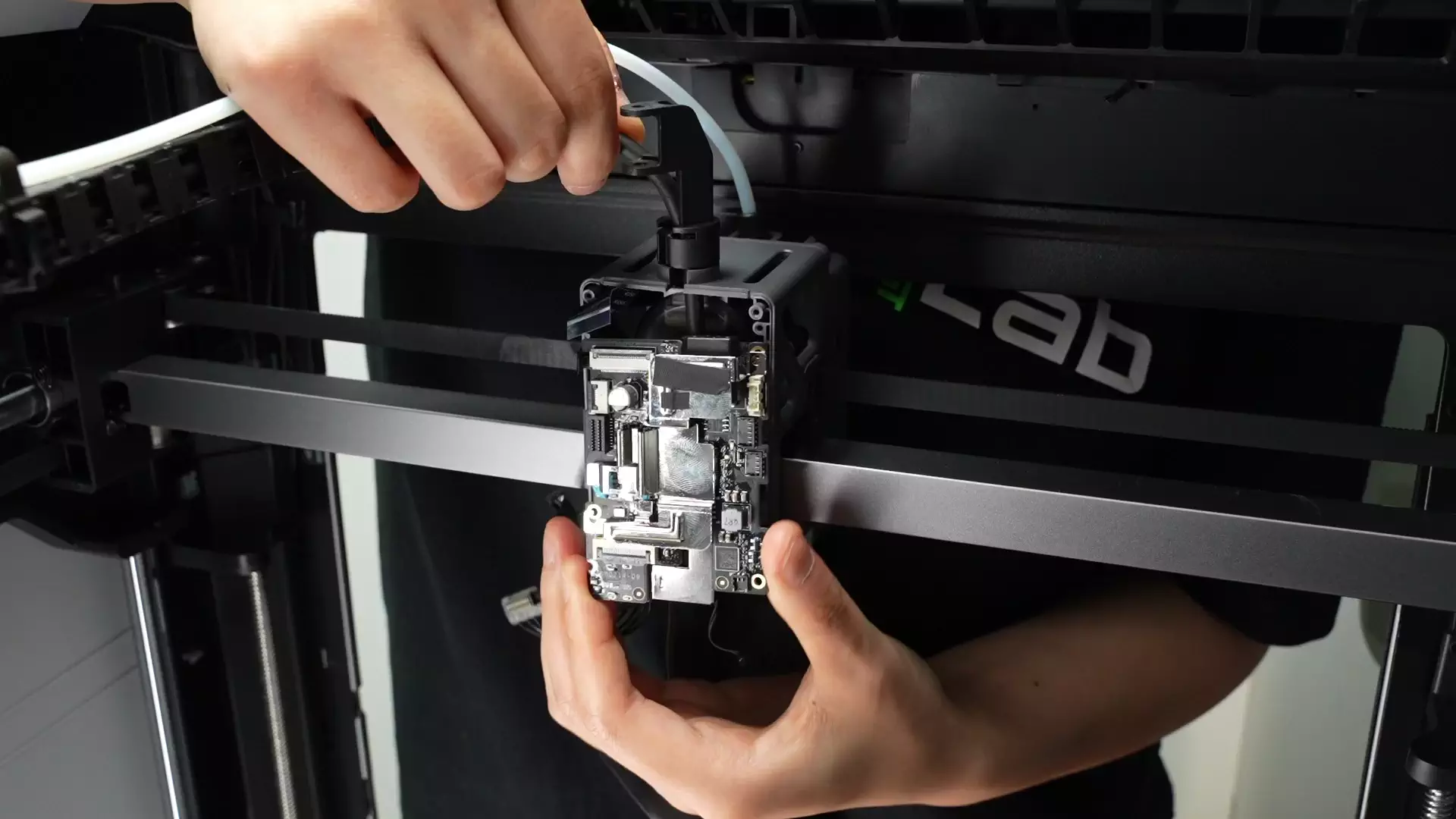
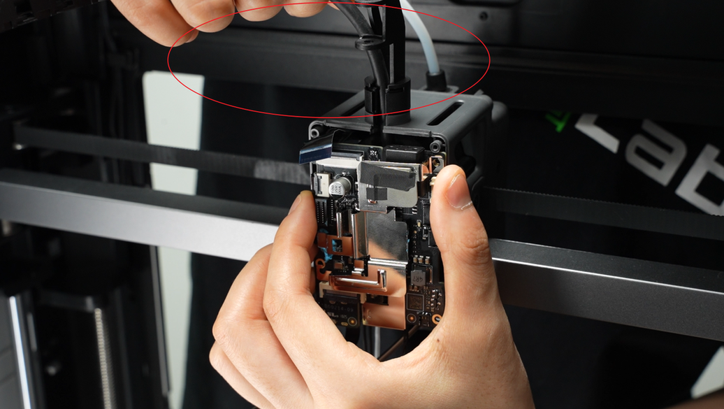
Carefully move the TH board (hold the heat sink with your fingers to prevent it from falling off) to create space to disconnect the filament sensor board plug, then disconnect the plug.
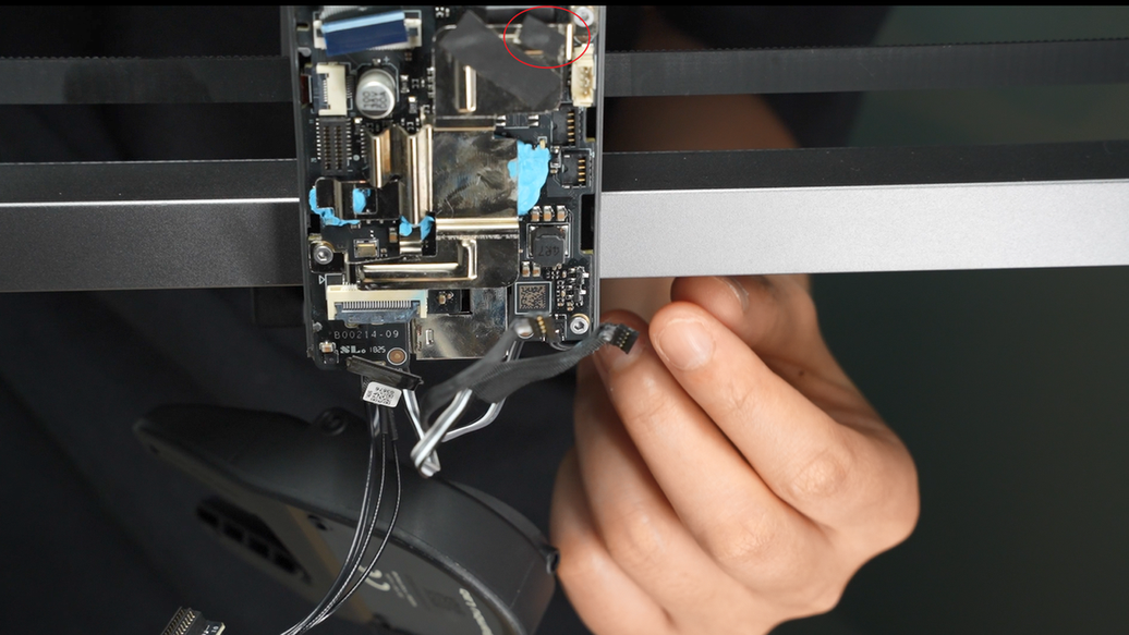
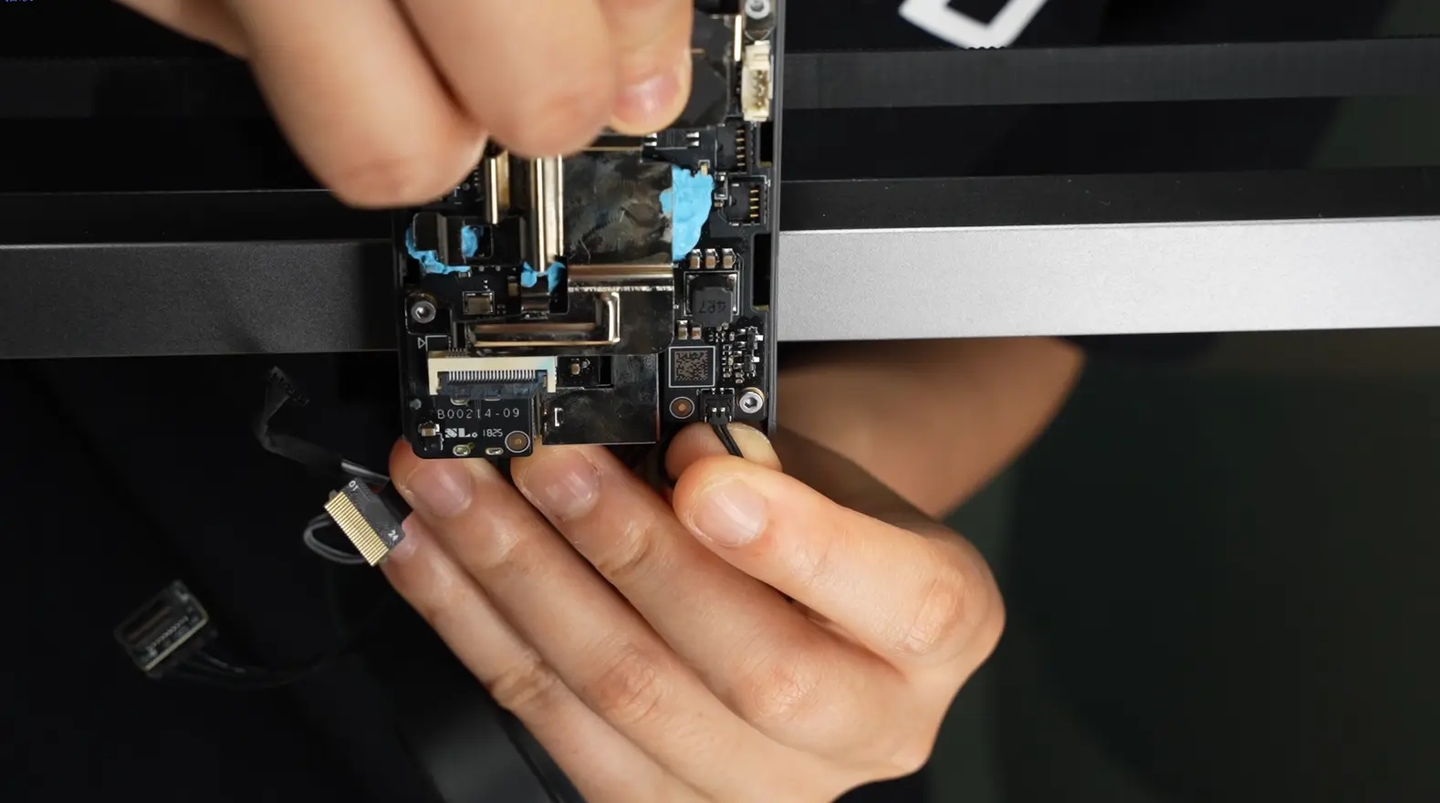
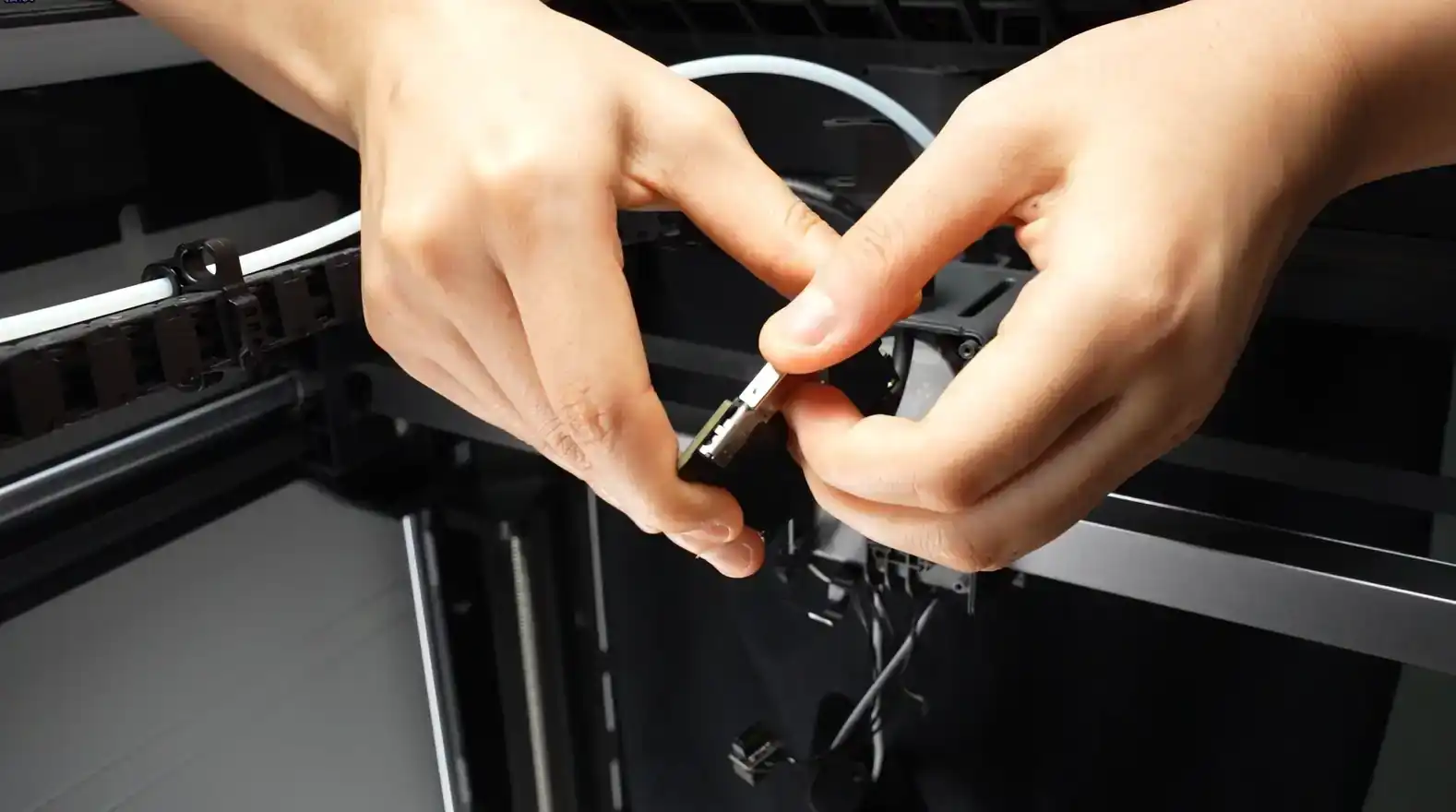
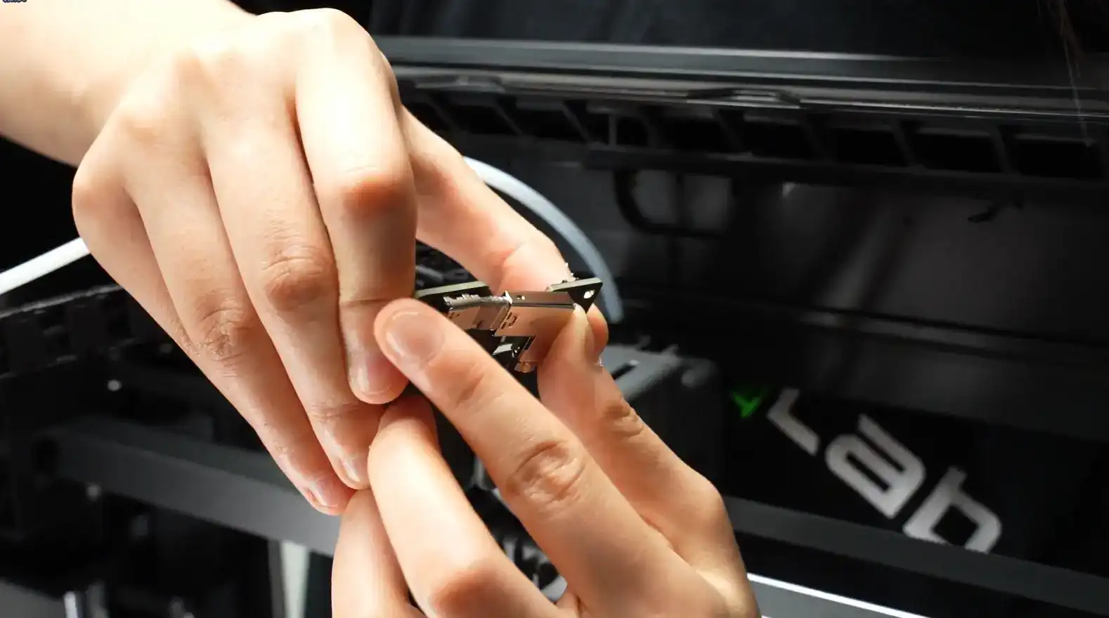
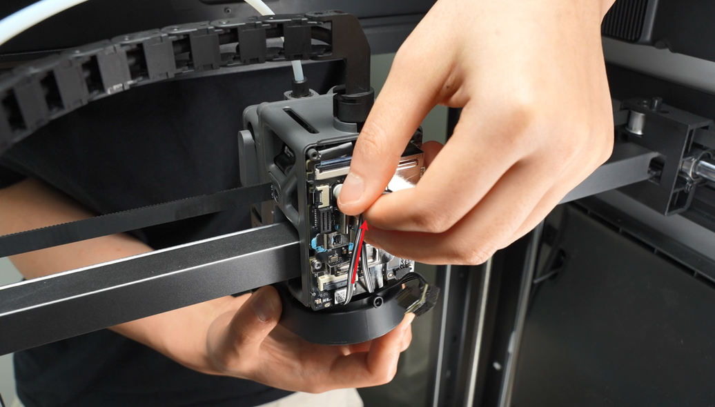
Flip the TH board and slowly wiggle to pull out the USB-C cable;
¶ Install the New TH Board
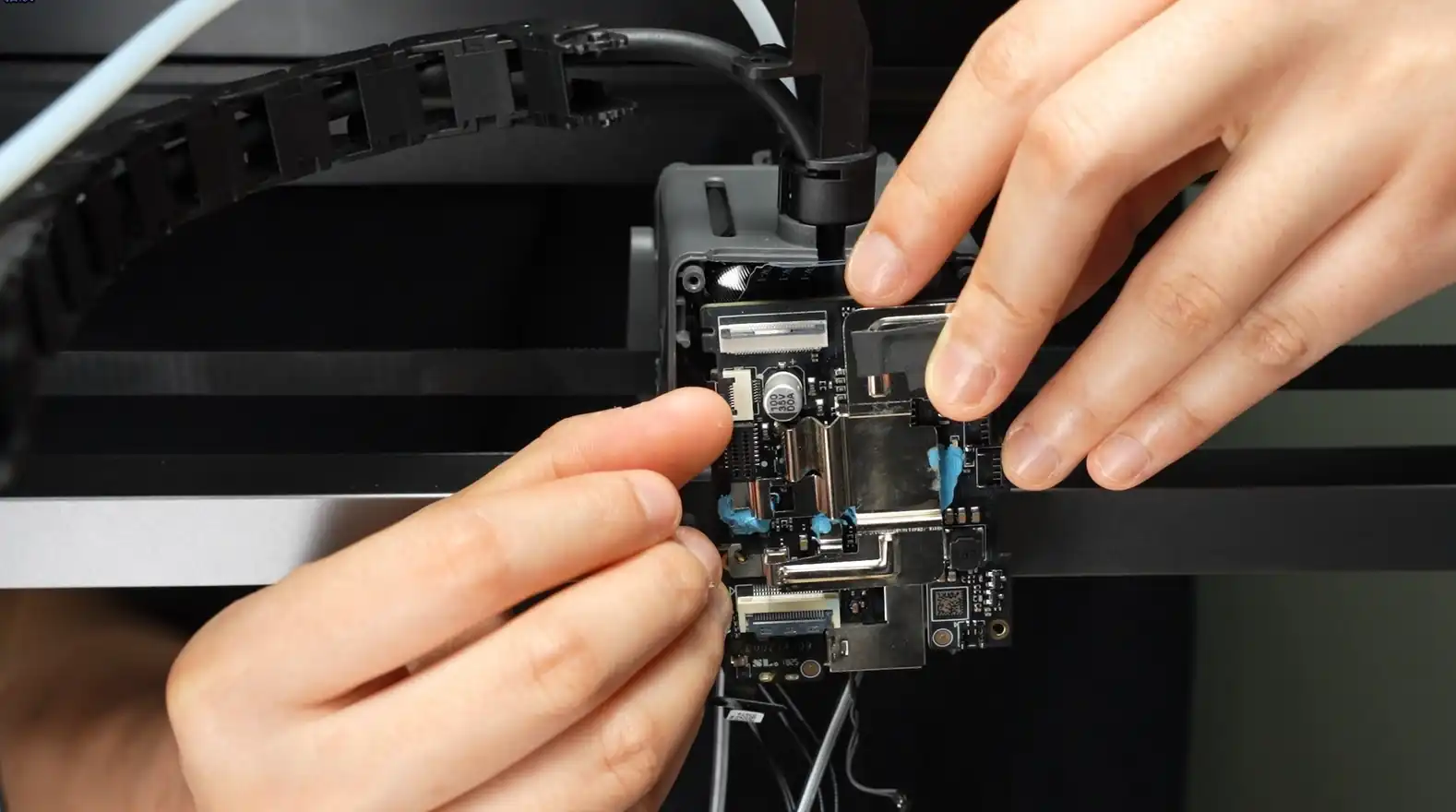
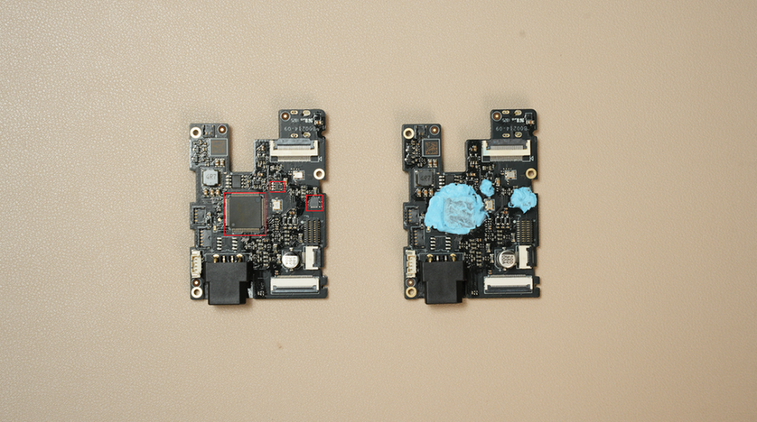
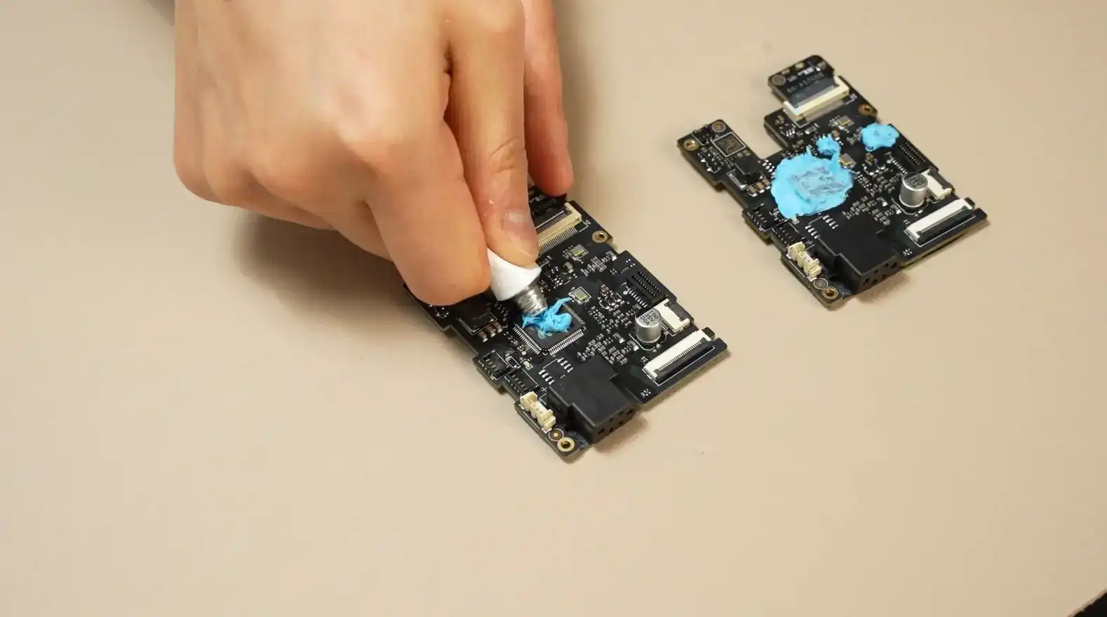
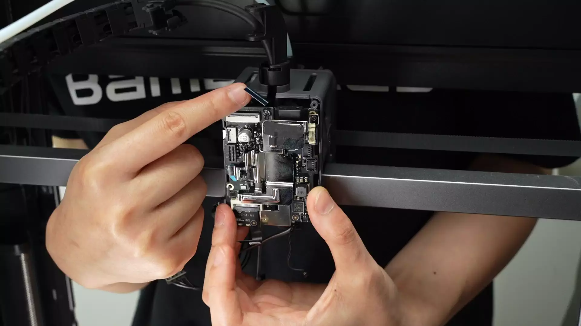
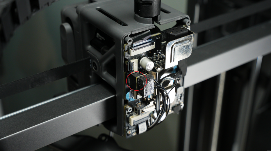
¶ Step 1: Apply Thermal Grease to the New TH Board
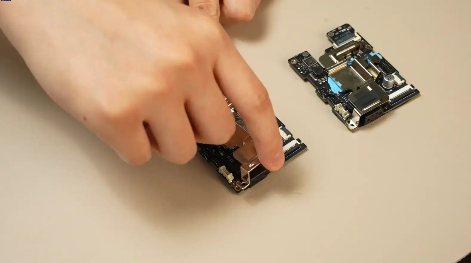
As shown in the picture, apply thermal grease to the electronic components in these 3 areas of the new TH board, and press the thermal grease with the heat sink. Please operate carefully and do not get thermal grease on the plugs or sockets; for a clear view of the application positions, you can also compare with the old TH board.
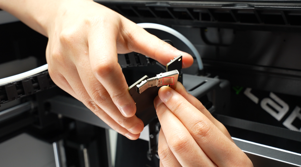
¶ Step 2: Connect the Filament Sensor Plug and USB-C Plug
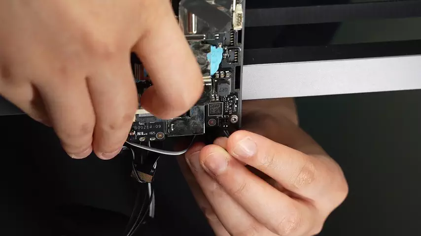
With letter A facing the back of the TH board, slowly wiggle and push the USB-C cable until it is fully inserted (you will feel resistance when it is fully inserted).
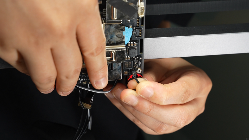
Flip the TH board (hold the heat sink with your fingers to prevent it from falling off), pull the USB-C cable upward to position the filament sensor board plug at a suitable height, and insert the plug.
¶ Step 3: Lock in the 3 Screws of the TH Board
After checking that the other 5 plugs are not pressed, align with the screw holes and lock in the 3 screws.
If it’s hard to align the screw holes, gently pull the USB-C cable upward to avoid excess length interfering with alignment.
Reinstall the cable chain bracket.
¶ Step 4: Insert All Plugs on the TH Board
Note: Connector 4 and Connector 5 are for the hotend fan and the part cooling fan, respectively. To avoid incorrect connections, the design ensures that the hotend fan has 5 pins while the part cooling fan has 4 pins. Please do not connect them incorrectly or force them in, as this may damage the connectors.
Note: When inserting the eddy current coil and 2 fan plugs, the metallic side should face upward.
After the toolhead camera and extruder motor plugs are fully inserted, the clips should be flat and the indicator lines should be horizontal.
Pre-align the screw holes of the fan, arrange the fan cable on the TH board, pull it upward, and fold the excess cable to avoid it being crushed by the fan housing or toolhead rear cover, which may cause fan malfunction.
After arranging the cables, insert the hotend heating assembly plug, and use the hotend heating assembly plug and cable to press the part cooling fan cable.
When inserting the hotend heating assembly, ensure it is aligned with the holes and not misaligned.
¶ Step 5: Install the Toolhead Rear Cover
Install the toolhead rear cover;
After installation, check that the part cooling fan cable is in the dedicated notch to avoid being squeezed by the rear cover frame;
Lock in the 2 rear cover fixing screws.

¶ Step 6: Install the Part Cooling Fan
Align with the screw holes and install the part cooling fan; when clamping the fan, be careful not to press the fan cable.
If the cable is too long, return to step 1 of the installation guide to fold the excess cable first.
Lock in the 3 screws to secure the part cooling fan.
¶ Calibration Steps After Operation
It is recommended to calibrate the printer after completing the replacement.
¶ Potential Issues and Solutions
If you encounter problems when installing the new extruder main board, please check the following potential issues and solutions:
¶ Hotend Temperature is 0℃
Check the hotend heating assembly connector to ensure it is properly inserted, as in step 3, and reconnect all cables.
Ensure all cables are aligned with the TH board.
If the problem persists, the thermistor wire (white wire) may be damaged.
¶ Hotend Cannot Heat
Check the hotend heating assembly connector to ensure it is properly inserted, as in step 3, and reconnect all cables.
Ensure all cables are aligned with the TH board.
If the problem persists, the heater wire (translucent wire) may be damaged.
¶ Printer Cannot Home
Check the eddy current coil plugs to ensure they are properly installed on the back of the TH board, as in step 3, and reconnect all cables.
¶ Filament sensor Board Not Working
Check the filament sensor plug to ensure it is properly installed on the back of the TH board, as in step 3, and reconnect all cables.
¶ End Notes
We hope this guide has provided useful information to help you solve the problem.
If you have any questions about this document, please contact our customer service team, and we will be happy to answer your questions and provide assistance!
Click here to access Bambu AI, and click here to submit a service ticket.