¶ Applicable Product Model
H2S
¶ When to Use
- Abnormal operation of the linear guideway assembly
- After-sales technical support recommends replacing the X-axis linear guideway assembly
¶ Required Tools and Materials
- H2.0 Hex Key Wrench (magnetic)
- H1.5 Hex Key Wrench (magnetic)
- Tweezers
- 60 minutes
It is strongly recommended that you purchase two high-quality hex key wrenches. Good hex key wrenches will significantly improve your maintenance experience. If the screwdriver loses its magnetism, you can remagnetize it using the magnet on the hotend.
¶ Screw List
¶ Screw List Involved in Disassembly and Assembly Steps of This Document
- Screw A: 2 screws on the top of the Extruder Unit: BT3x12
- Screw B: 2 screws on the bottom of the Extruder Unit: M2.5x5
- Screw C: 3 screws for the Hotend Heating Assembly: M3×10
- Screw D: 3 screws (for the back of the Part Cooling Fan (co-locked with the rear cover) and the Toolhead Rear Cover) + 2 screws for the Eddy Current Coil (same size as Screw D), total 5 screws: BT2x6.5
- Screw E: 2 screws for the Toolhead Camera: BT2×8
- Screw F: 2 screws on the left and right sides of the Part Cooling Fan: BT2x5
- Screw G: 3 screws for the TH Board: BT2x5
- Screw H: 2 screws for the Hotend Fan: BT2x4
- Screw I: 1 screw for the AP Board Cover: BT2.6x8 (not shown in the figure below)
- Screw J: 4 fixing screws for the Filament Buffer: BT3×8 (not shown in the figure below)

¶ Disassembly Guide
Some steps in this document are only for demonstrating operation actions, and some images may have continuity errors. Please focus only on the specific operations and ignore the continuity errors.
¶ Step 1: Lower the Heatbed
Lower the heatbed via the screen, ensure the hotend is at room temperature, then turn off the printer.


¶ Step 2: Remove the PTFE Tube
Press the pneumatic connector on the top of the toolhead to disconnect the PTFE tube above the toolhead. Push out the pneumatic connector of the filament buffer and press to unlock it.
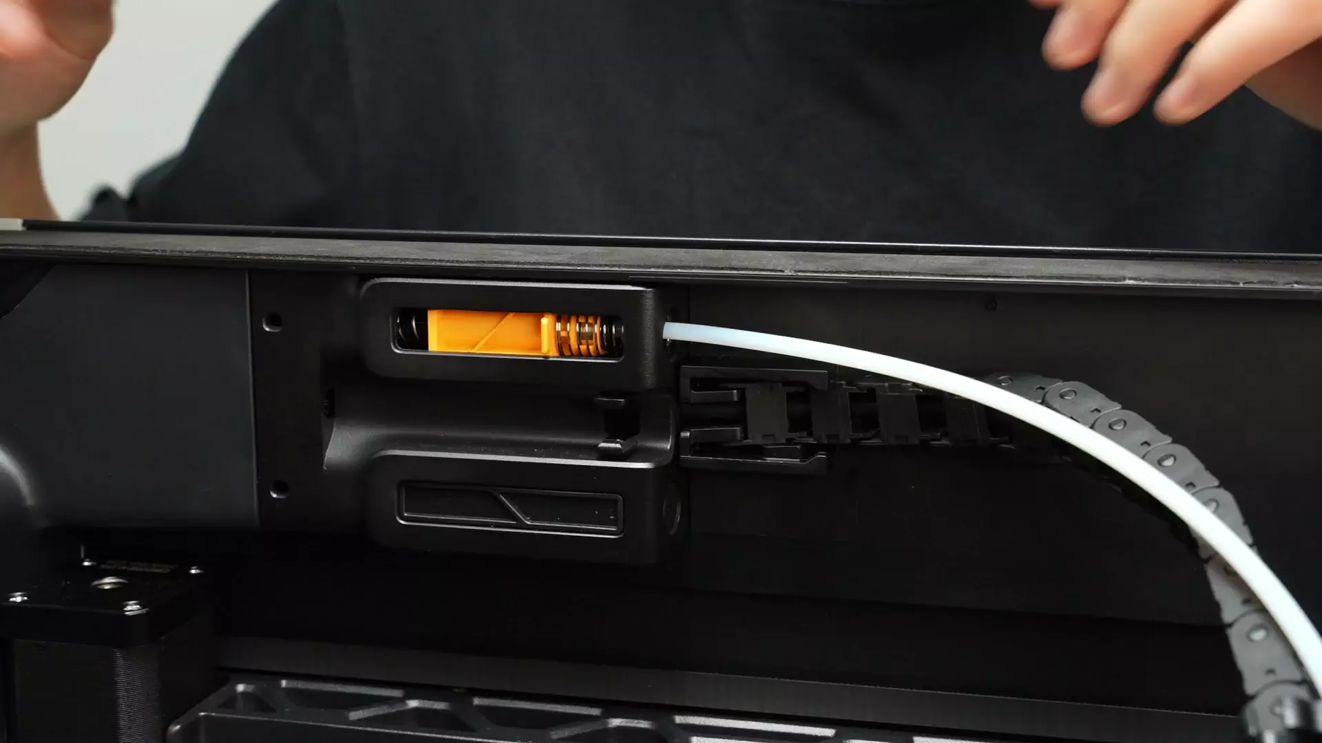
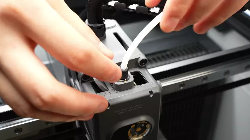
Pull the PTFE tube out of the cable chain.

Then unlock the pneumatic connector at the filament inlet on the back of the printer and remove the PTFE tube.

¶ Step 3: Remove the Hotend
Refer to this tutorial to remove the hotend (Click here to jump)
¶ Step 4: Remove the TH Board
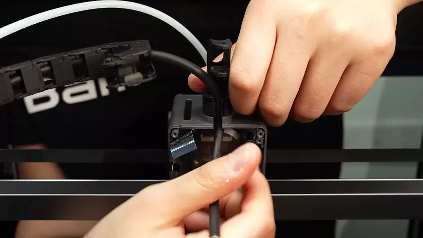
You can refer to this Wiki to remove the TH Board. You only need to follow the steps up to disconnecting the Feeder Hall Sensor connector—there is no need to disconnect the TH Board from the USB-C cable.
Pull the cable out of the cable chain bracket.
¶ Step 5: Remove the Part Cooling Fan
Refer to Step 3 of the Part Cooling Fan disassembly and assembly guide: pull the cable out of the cable organizer clip and remove the Part Cooling Fan.

¶ Step 6: Remove the Hotend Heating Assembly
Refer to Step 4 of the Hotend Heating Assembly disassembly and assembly guide:
- Take out the Part Cooling Fan cable and Hotend Heating cable from the cable management slot;


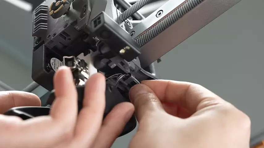
- Remove the 3 screws of the Hotend Heating Assembly, then take off the Hotend Heating Assembly and the gray heat shield;


¶ Step 7: Remove the Toolhead Camera
Refer to Step 5 of the Toolhead Camera disassembly and assembly guide:
Pry open the Toolhead Camera cover and unscrew the 2 exposed screws (one screw requires inserting the screwdriver under the flat cable). It is recommended to loosen Screw 1 by a few turns first, then fully remove Screw 2, and finally fully remove Screw 1.
 |
 |
|---|
Remove the flat cable from the toolhead frame. Note that the flat cable at the clip may have adhesive backing in some batches—you need to wiggle it left and right to loosen it.
¶ Step 8: Remove the Hotend Fan and Eddy Current Coil
Refer to Step 5 of the Eddy Current Coil disassembly and assembly guide to remove the Hotend Fan and Eddy Current Coil.


- Remove the 2 screws of the Hotend Fan and take off the Hotend Fan; (This is only for demonstrating the operation—there may be continuity errors, please ignore)


- Remove the 2 screws of the Eddy Current Coil and route the cable around the area indicated by the arrow; (This is only for demonstrating the operation—there may be continuity errors, please ignore)


- Take out the Hotend Fan cable and Eddy Current Coil cable from the cable management slot in sequence, then remove the old Eddy Current Coil; (This is only for demonstrating the operation—there may be continuity errors, please ignore)
¶ Step 9: Remove the Extruder Unit
Refer to Step 6 of the Extruder Unit disassembly and assembly guide to remove the Extruder Unit.


Subsequent steps are only for demonstrating operation actions and may have continuity errors—please ignore them.
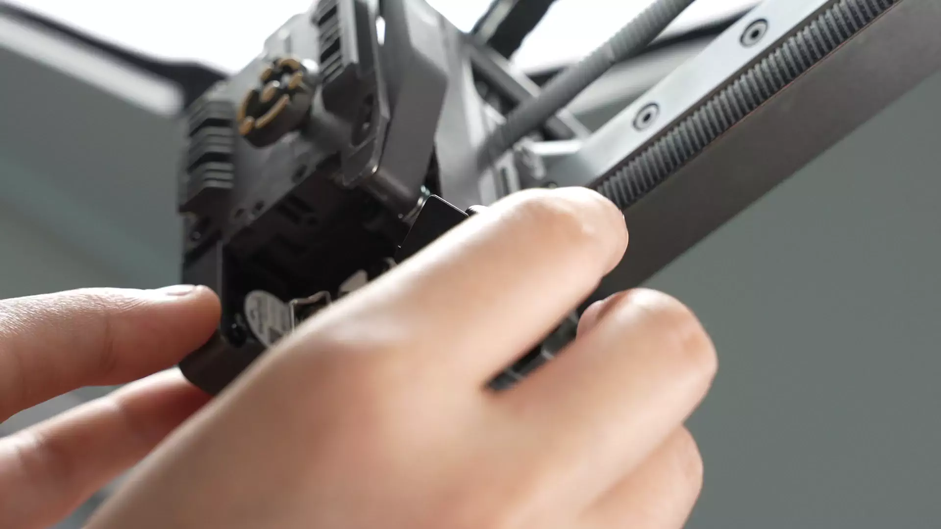
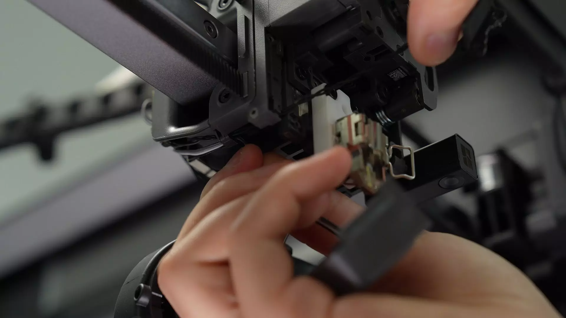
Since the FPC cable of the Extruder Unit has adhesive backing and a 90-degree bend (especially the thin Feeder Hall Sensor cable), extra care must be taken when removing the Extruder Unit to avoid tearing the cable.
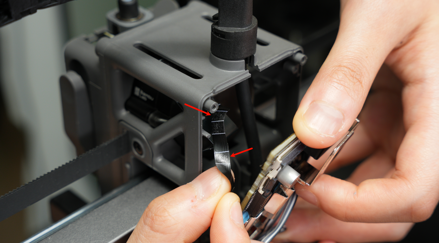
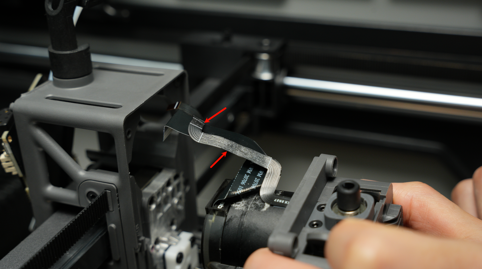
Peel off the adhesive backing of the cable from the middle frame in the direction opposite to the middle frame.
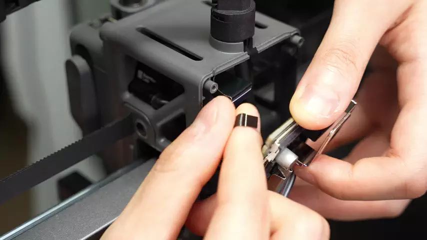
If the Extruder Feeder Hall Sensor cable is stuck to the plastic middle frame, move the cable first to separate it from the middle frame. If the top motor cable is in the way, use a plastic tool to press it down.
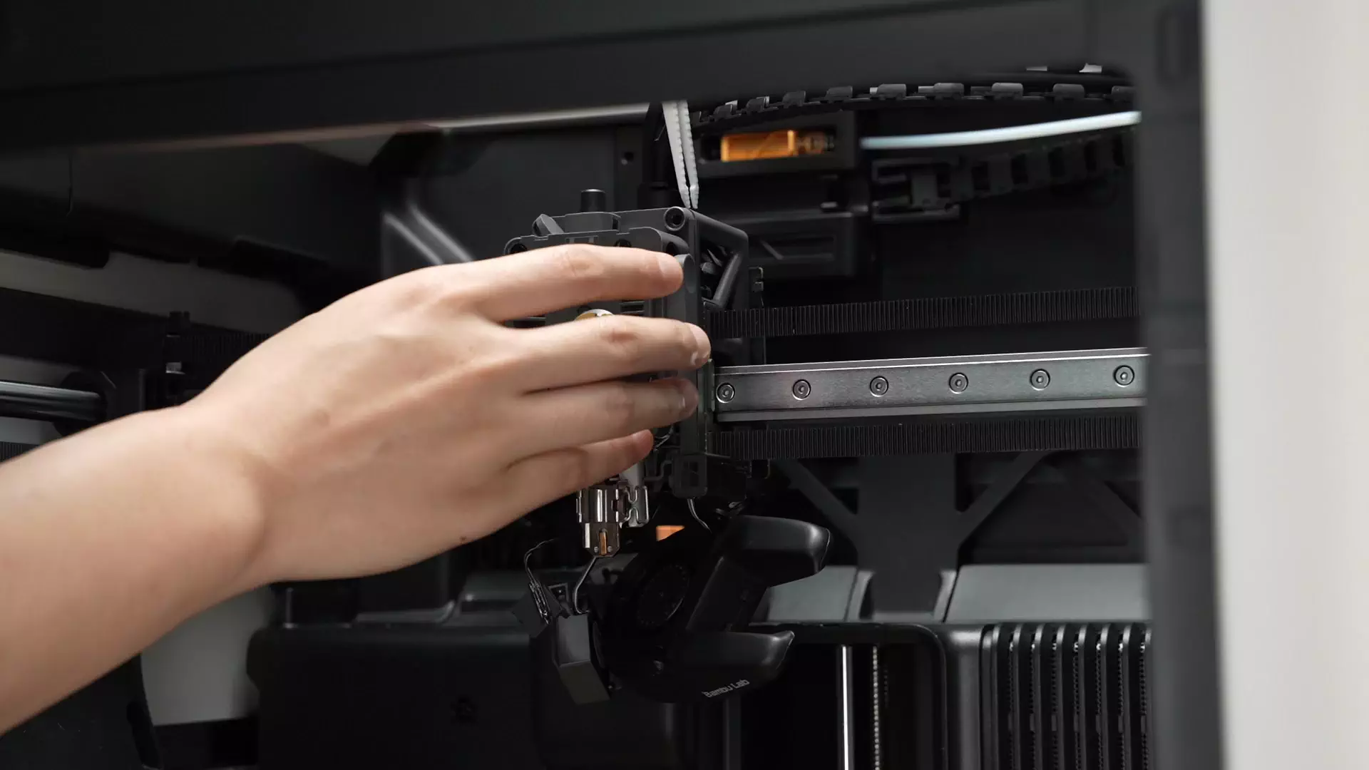
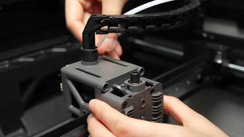
Wiggle the Extruder Unit left and right, then pull it out from the front.
If the sensor cable or motor cable interferes with the middle frame, gently press it down with your finger or a plastic tool; do not pull hard.
¶ Step 10: Remove the Belt
Unscrew the 2 screws on the Belt Holder and remove the Belt Holder.


Remove the Belt Holder on the other side using the same method.


¶ Step 11: Remove the AP Cable Organizer Cover
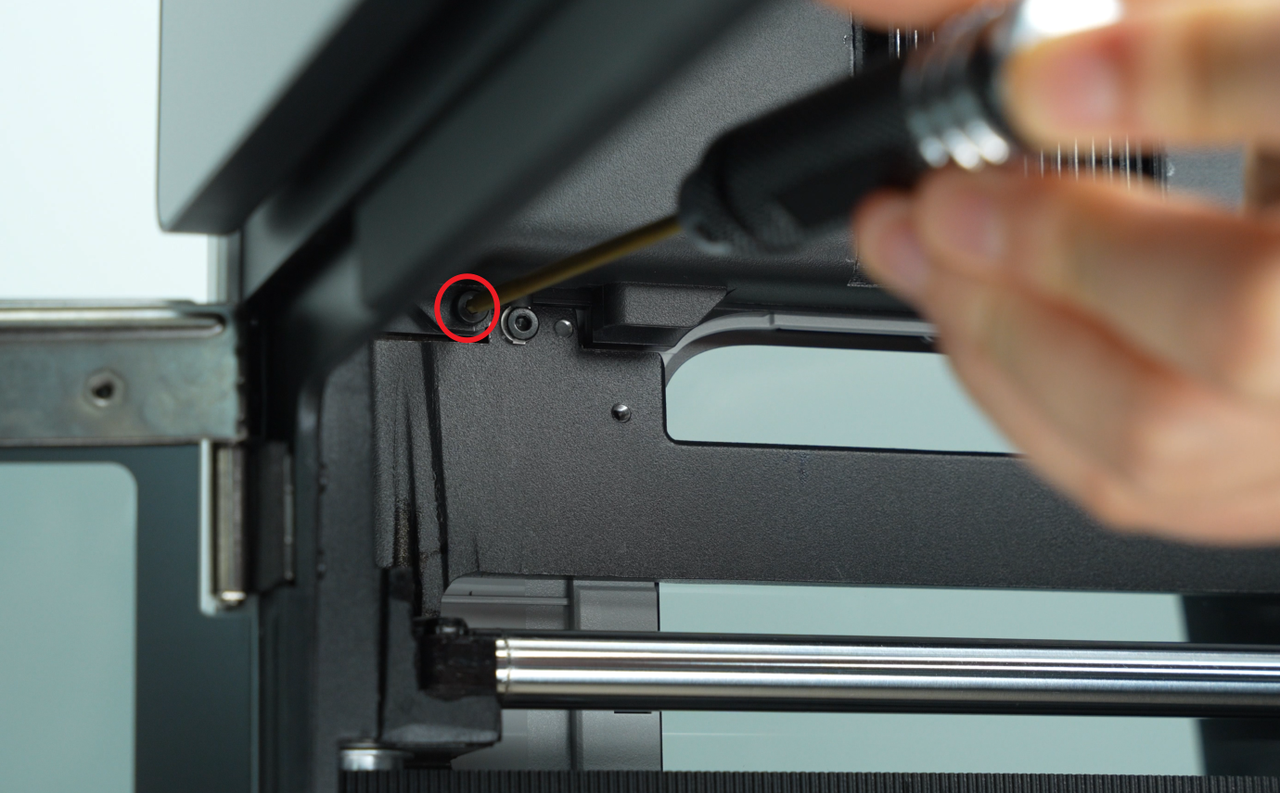
Use an H2.0 hex key wrench to remove 1 fixing screw (BT2.6x8), then take off the AP Board Cover from the side near the front door.
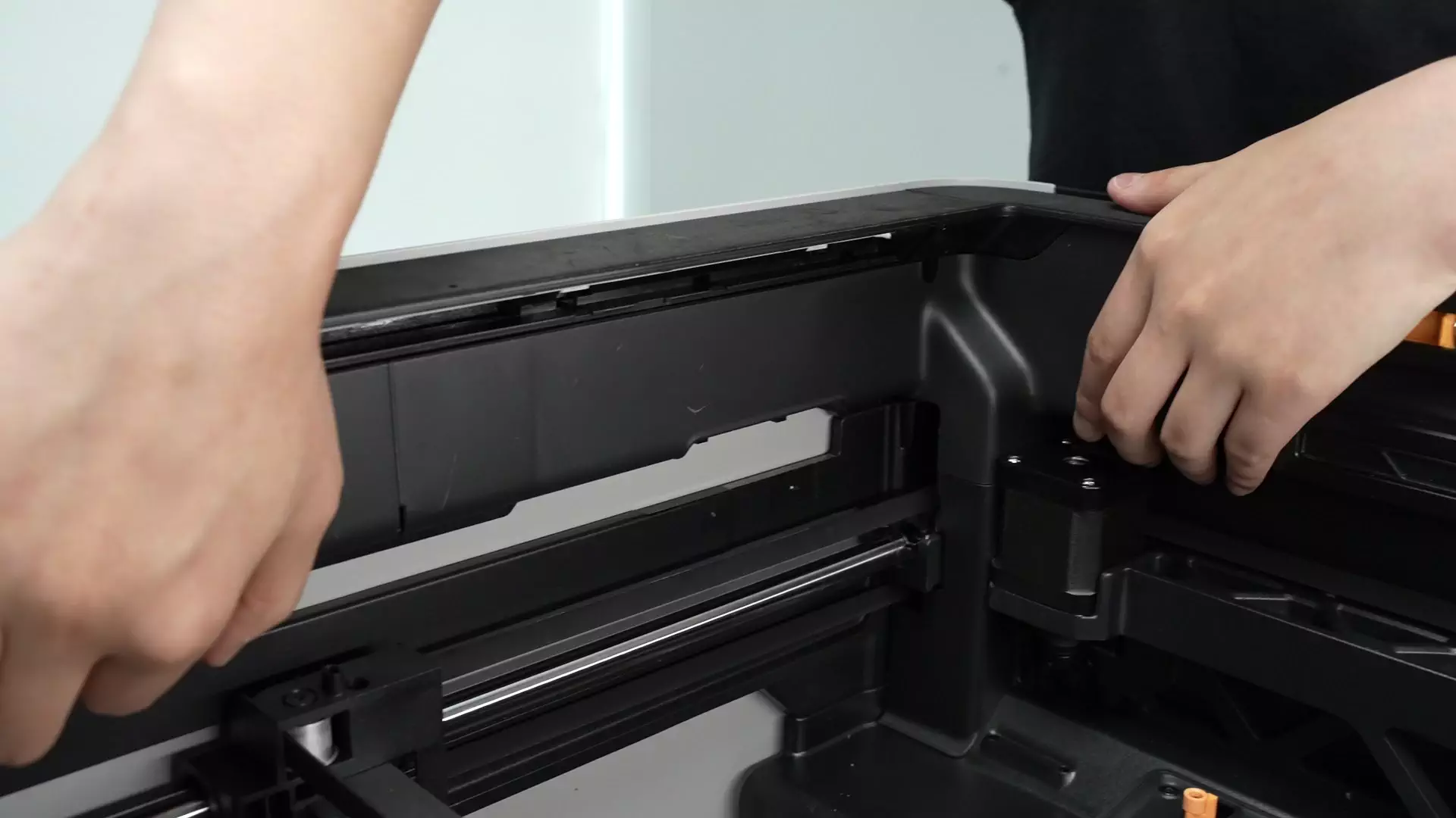
¶ Step 12: Attach Non-Marking Tape to Both Sides of the Linear Guideway to Prevent Slider Balls from Falling Out
Attach non-marking tape to both sides of the toolhead. If no non-marking tape is available, attach paper to the linear guideway and secure it with transparent tape. The purpose of this step is to restrict the movement of the toolhead and prevent it from sliding off the linear guideway when the guideway is removed.

¶ Step 13: Remove the Linear Guideway Assembly
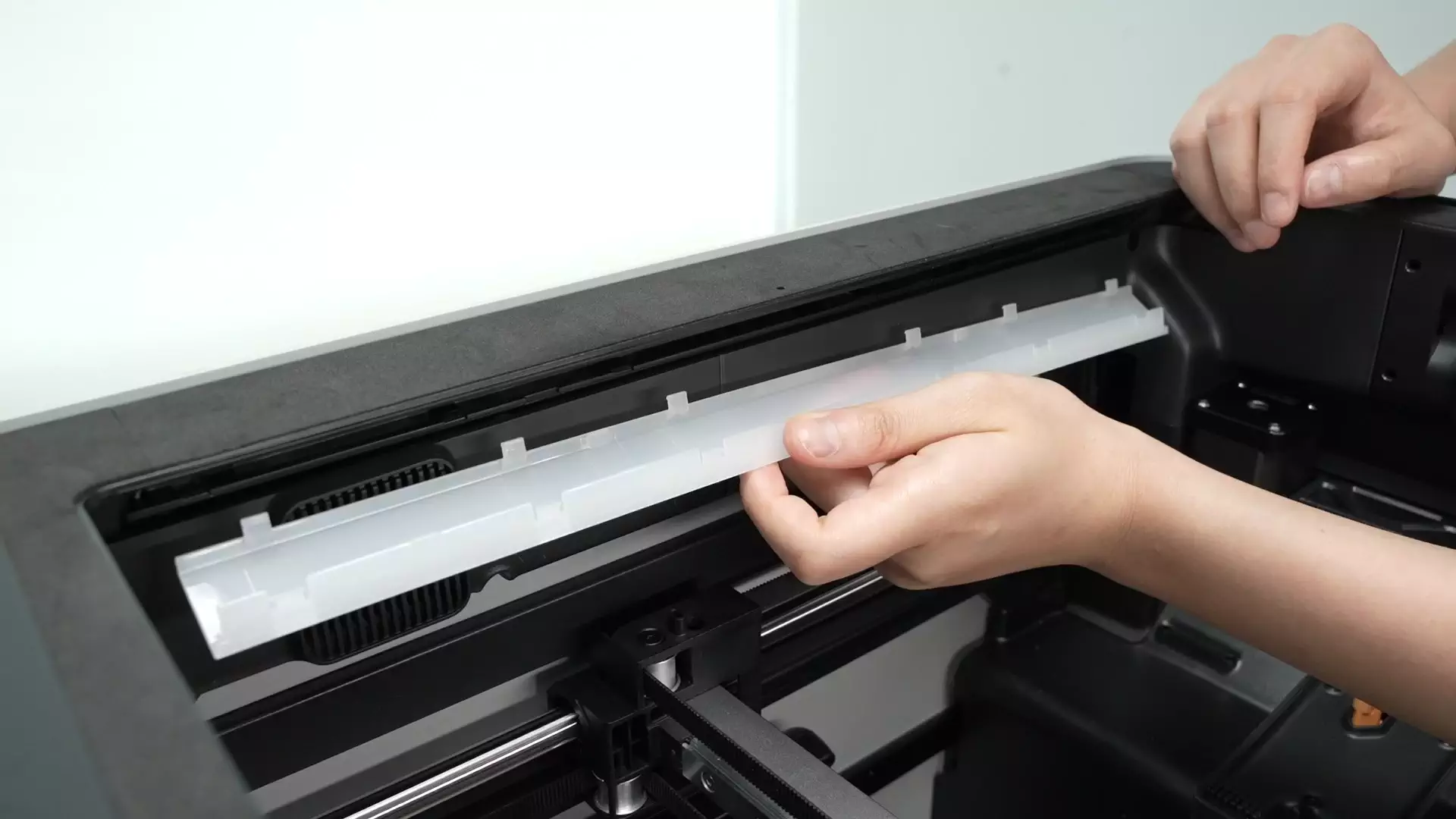
Use tweezers to assist in removing the LED light covers on the left and right sides.


There is a reserved hole in the middle of the frame. Insert an L-shaped hex key wrench through this hole to easily remove the linear guideway screw on the top of the carriage.
Remove the linear guideway screw on the other carriage using the same method.


Then remove the 4 screws on the side of the linear guideway and the 2 screws at the bottom of the carriage.


After removing all screws, move the carriage back and forth to remove the linear guideway. When removing the guideway, first disengage the right-side guideway from the carriage, then disengage the left-side guideway from the carriage, and finally take out the guideway at an angle.

¶ Assembly Guide
¶ Step 1: Install the Linear Guideway Assembly
When installing the new linear guideway assembly, first insert the right-side guideway into the carriage, then insert the left-side guideway into the carriage. Push the guideway forward until it can no longer move—this step uses the front door pillar for positioning to ensure the guideway is parallel.


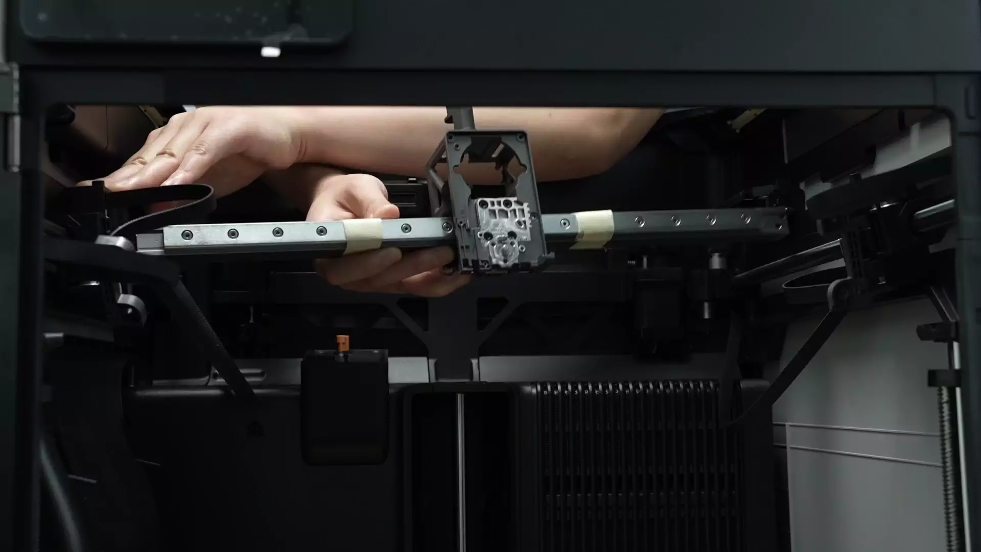
To ensure the linear guideway is parallel, the guideway must be pushed to the foremost position before installing the guideway screws. Unlike the disassembly step, the guideway cannot be pushed to the middle position to install screws with an L-shaped hex key wrench. Therefore, it is recommended to use a short hex key wrench to directly install the 2 screws on the carriage, the 4 screws on the side of the guideway, and the 2 screws at the bottom of the carriage.
Note: The screws on the top and bottom of the carriage are fine-thread screws, while the screws on the side of the linear guideway are coarse-thread screws—do not mix them up.
 |
 |
 |
 |
 |
 |
Align the clips and reinstall the left and right LED light covers.


¶ Step 2: Remove the Cable Ties
After installing the linear guideway assembly, use needle-nose pliers to cut the cable ties on both sides of the toolhead. (This is only for demonstrating the operation—there may be continuity errors, please ignore)

In actual scenarios, the cable ties are located on both sides near the empty toolhead middle frame.

¶ Step 3: Install the AP Cable Organizer Cover
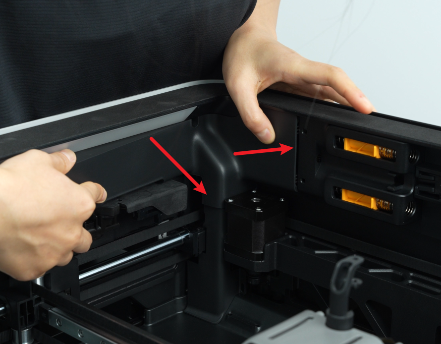
First, fasten the AP Board Cover back from the side near the printer’s rear panel. Press both positions indicated by the arrows into place: the right side should be flush with the filament buffer, and the bottom should be flush with the cable protection cover. Then use an H2.0 hex key wrench to tighten 1 fixing screw (BT2.6x8).

Note: Before installing the AP Board Cover, check whether the cables block the PTFE tube to avoid affecting the subsequent installation of the PTFE tube.
¶ Step 4: Install the Extruder Unit
With the Feeder Hall Sensor cable on top and the Extruder Motor cable on the bottom, insert the Extruder Unit into the toolhead middle frame.

If any cable is raised, use a plastic tool or your finger to flatten it before pushing further to avoid damaging the cable.

Stick the adhesive backing of the cable back to the plastic middle frame.

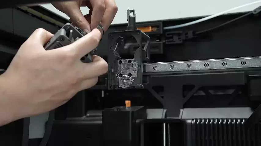
Install the 4 screws for the Extruder Unit.

¶ Step 5: Install the Toolhead Camera
Subsequent steps are only for demonstrating operation actions and may have continuity errors—please ignore (the Hotend Fan, Eddy Current Coil, and Hotend Heating Assembly are not actually installed yet).
Pre-align the screw holes, route the flat cable through the cable slot, and stick the remaining adhesive backing of the flat cable to the corresponding position on the middle frame.
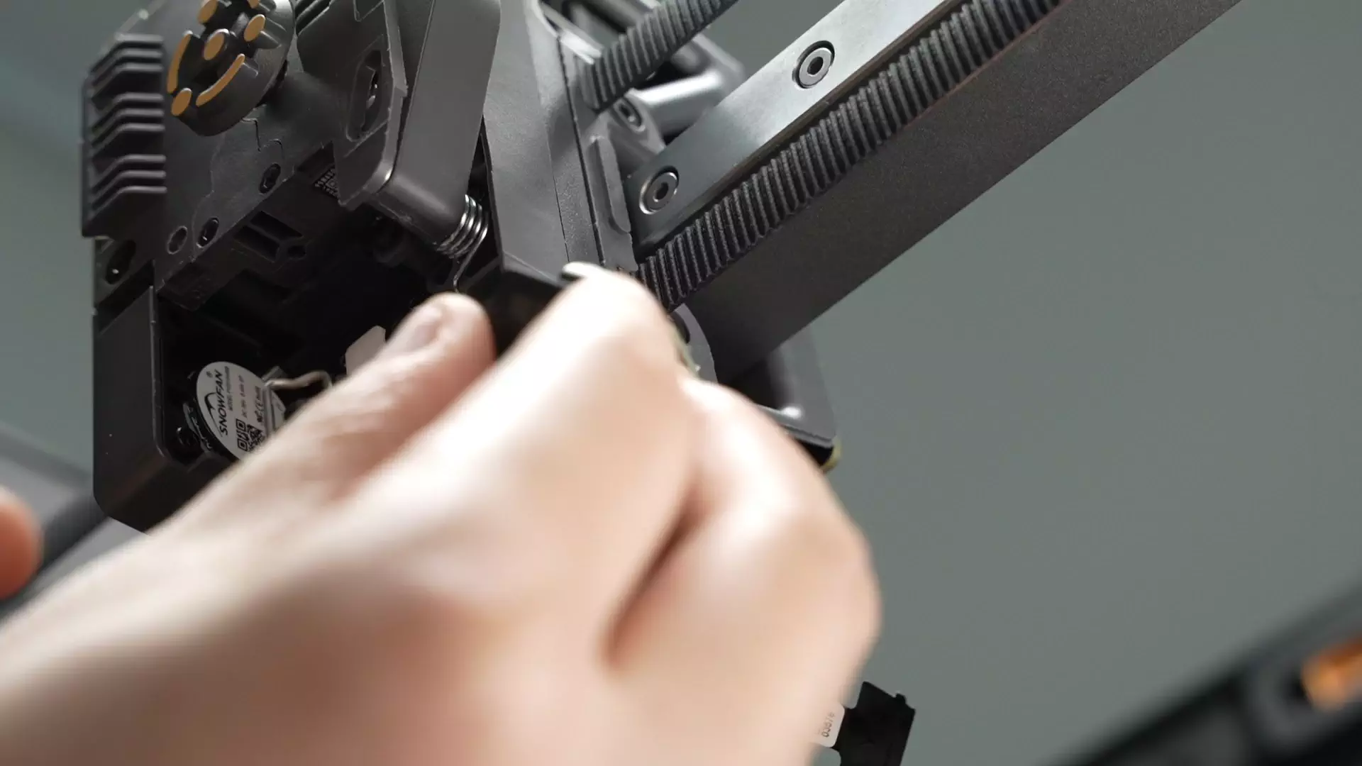
Align the screw holes, reinstall the Toolhead Camera, and tighten the 2 fixing screws. When installing the screws: first pre-tighten Screw 1 by a few turns, then fully tighten Screw 2, and finally continue tightening Screw 1.
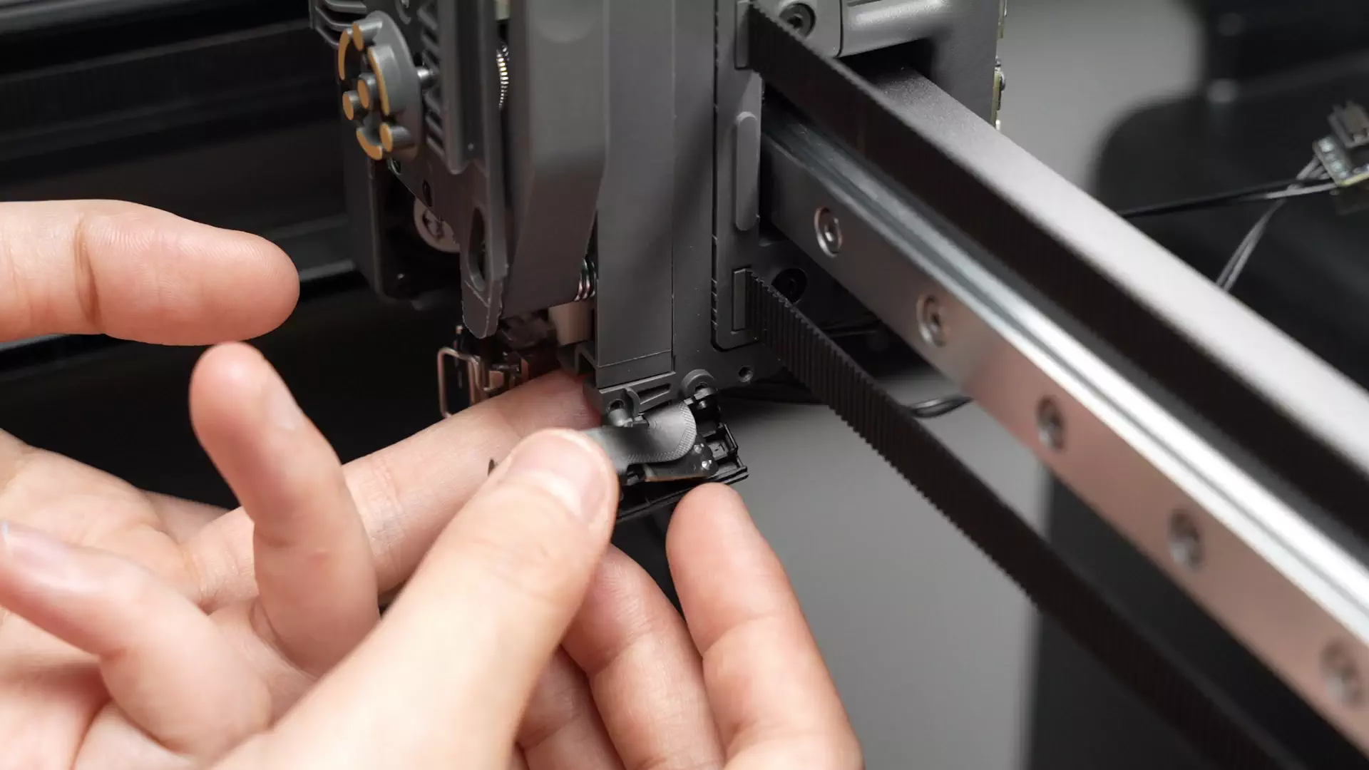

Snap the Toolhead Camera cover back into place.

¶ Step 6: Install the Hotend Heating Assembly
Subsequent steps are only for demonstrating operation actions and may have continuity errors—please ignore (the Hotend Fan and Eddy Current Coil are not actually installed yet).
Install the heat shield (extremely important—do not omit it), align with the screw holes and the middle positioning point, then reinstall the Hotend Heating Assembly;
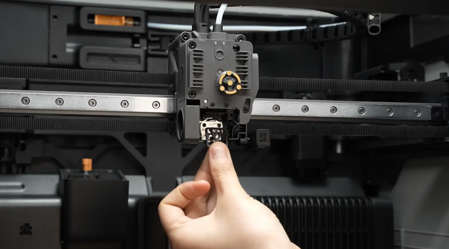
Tighten the 3 fixing screws;

- Clip the new Hotend Heating Assembly cable into the cable management slot. After clipping the cable, press the area indicated by the arrow as shown in the video.

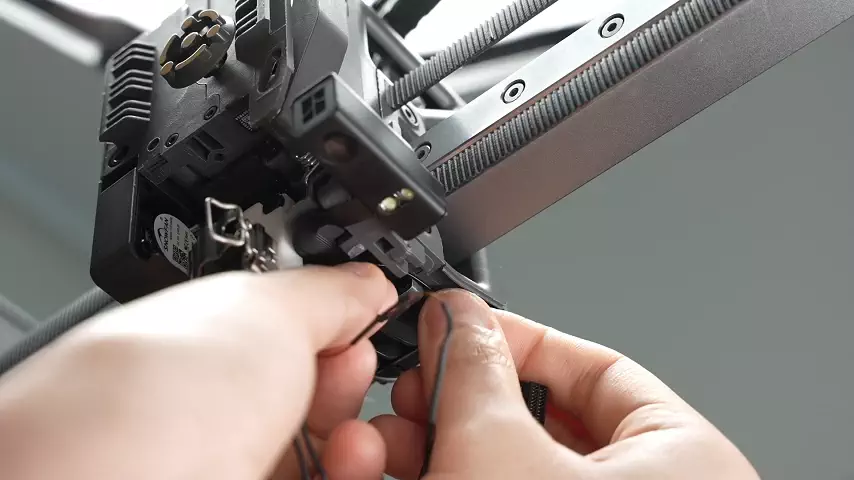
¶ Step 7: Install the Hotend Fan and Eddy Current Coil
Subsequent steps are only for demonstrating operation actions and may have continuity errors—please ignore.
Clip the Eddy Current Coil cable and Hotend Fan cable into the cable management slot in sequence.
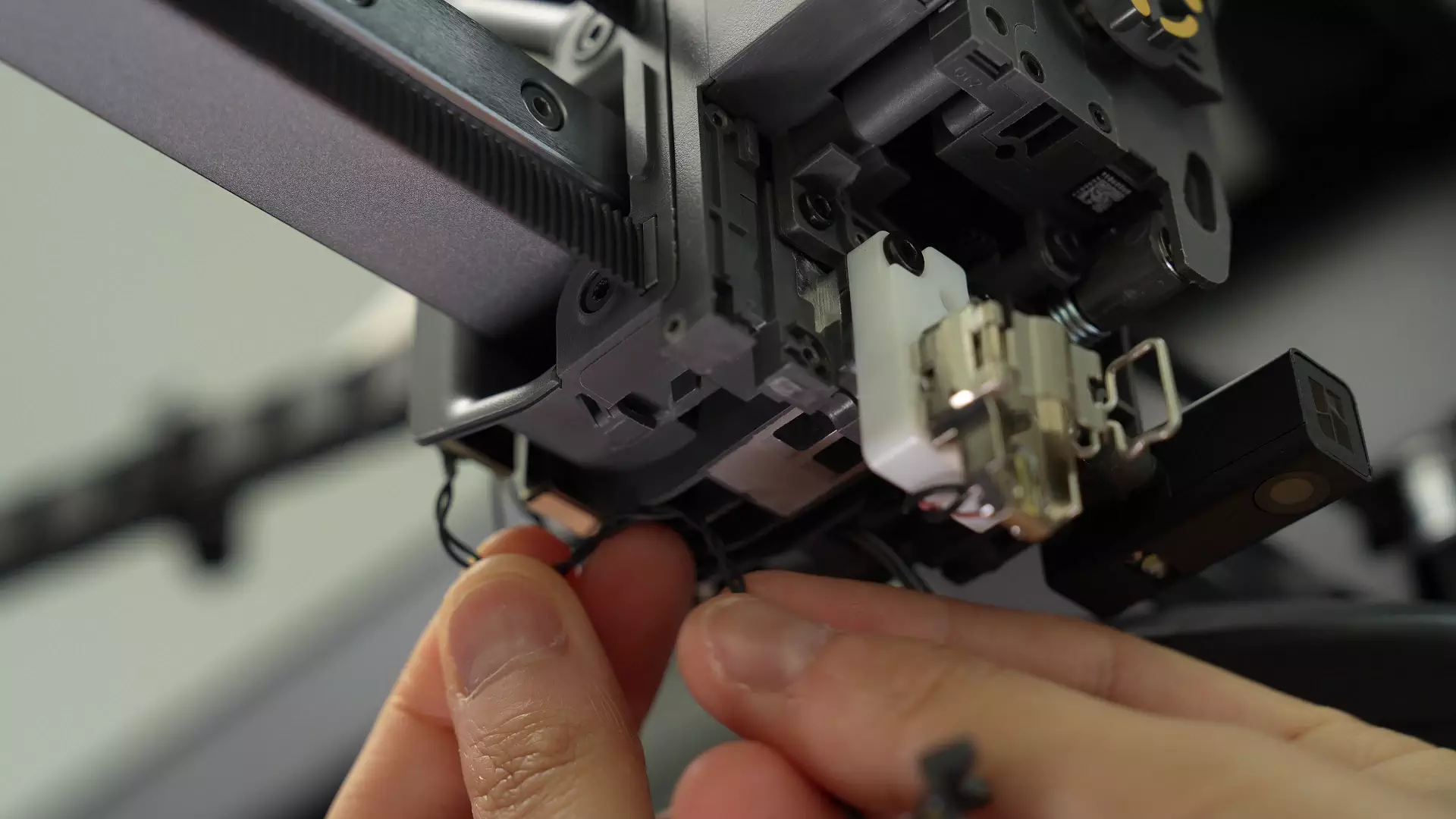
Note: When viewed from the front, the cable must pass through the left side of the cable management post indicated by the arrow (viewed from the front).


Align the screw holes so that the arcs of the two structural parts overlap. Install the Eddy Current Coil screws. When installing the screws: first pre-tighten one screw, then fully tighten the other screw, and finally re-tighten the first screw to ensure the Eddy Current Coil is level after installation (important).


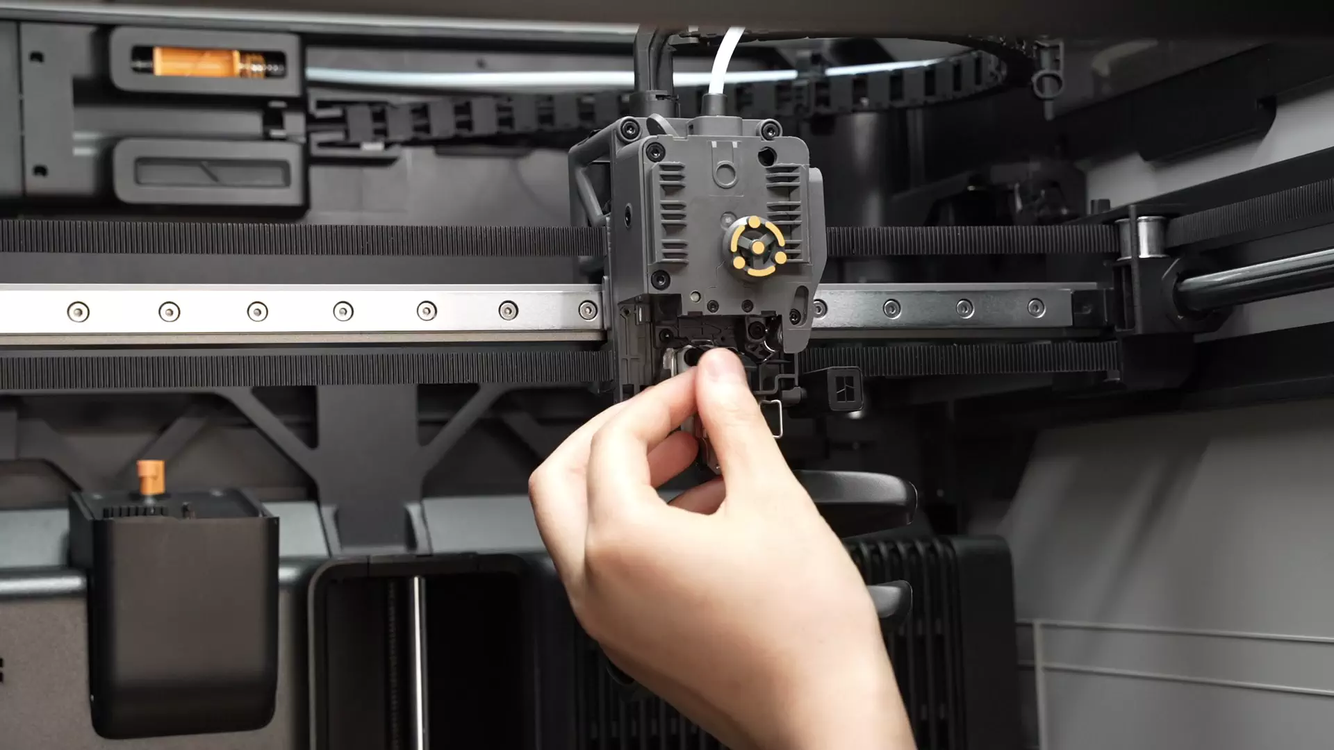
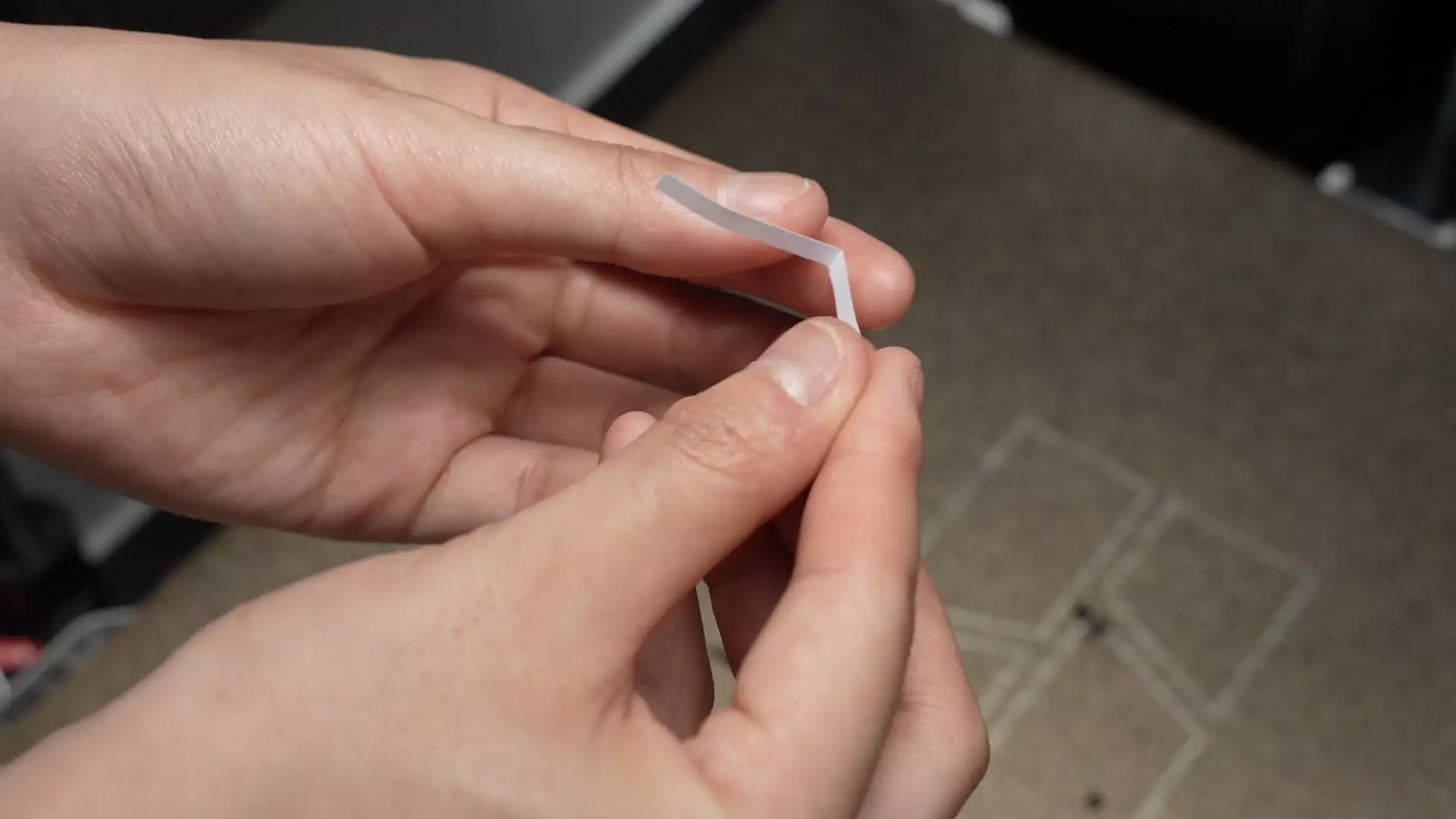
Calibrate the Eddy Current Coil installation position (important): Reinstall the hotend, fold a piece of appropriately sized A4 paper in half, and insert it into the gap between the hotend and the Eddy Current Coil. When pulling the paper back and forth, you should feel a slight frictional resistance, but the paper should still move freely. This indicates the gap between the hotend and the Eddy Current Coil is approximately 0.2-0.3mm.
- Face the labeled side of the fan toward the hotend and align with the screw holes (refer to the red and yellow circles in the figure below);

Fold the fan cable into the groove shown in the figure, then install the fan.

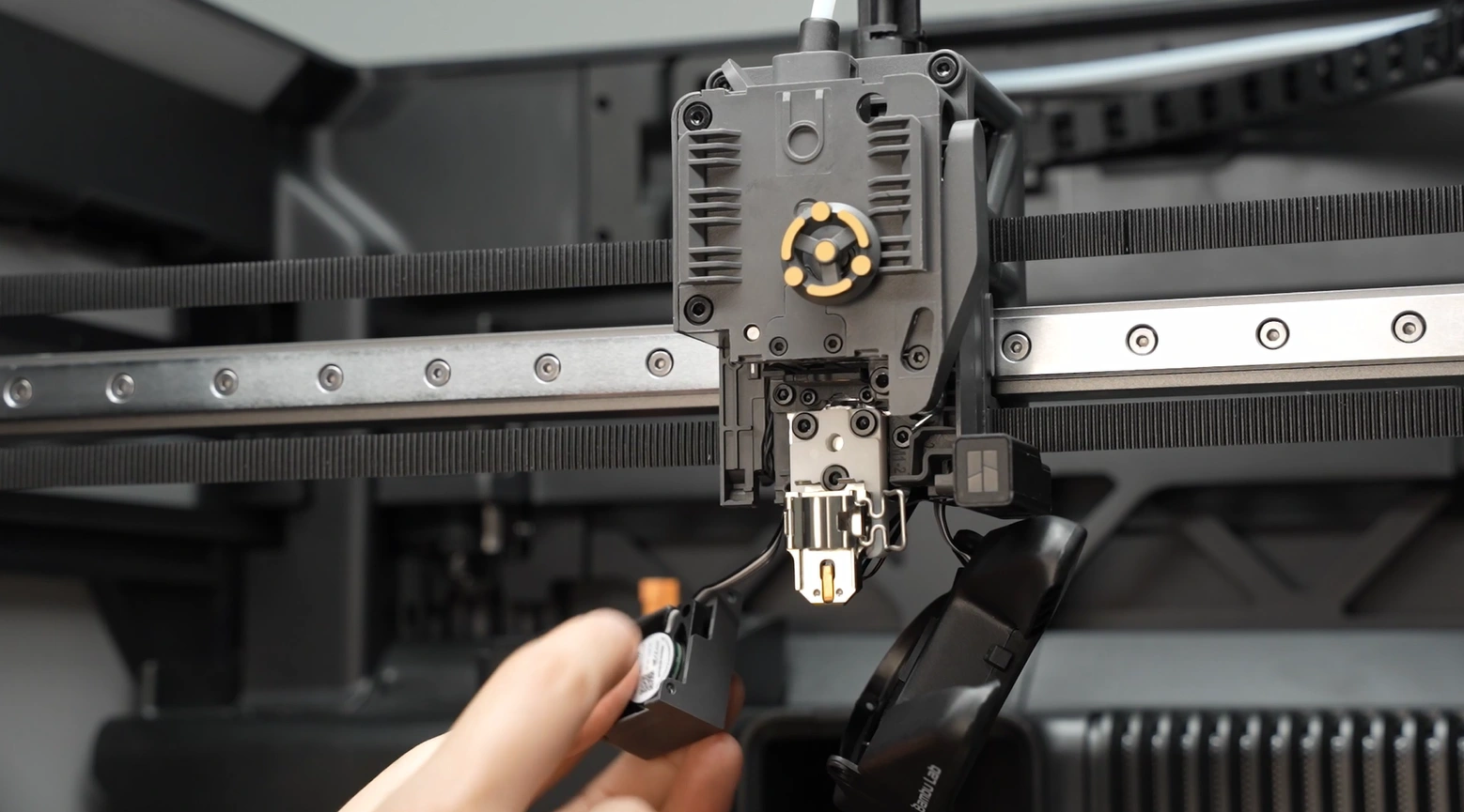
- Tighten the two fixing screws of the fan.

¶ Step 8: Install the Part Cooling Fan
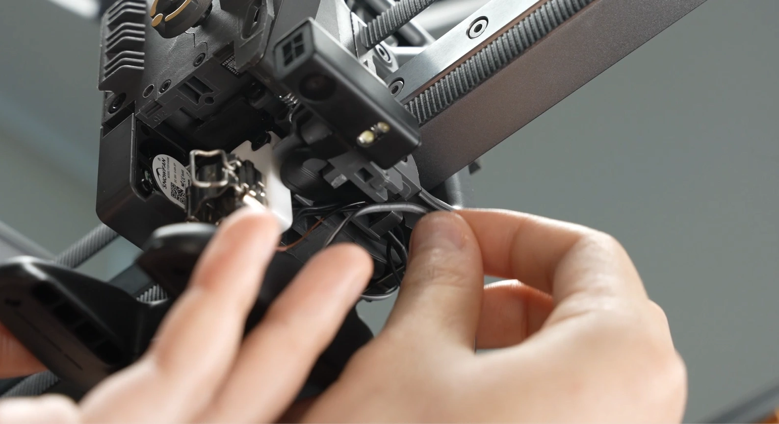
Clip the Part Cooling Fan cable into the cable clip;

¶ Step 9: Install the TH Board
Clip the USB-C cable into the cable chain bracket.
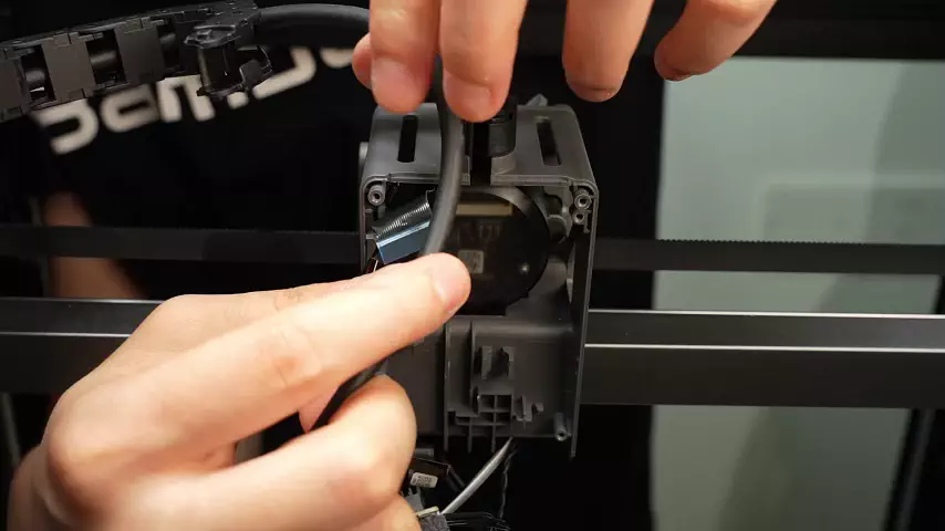
You can refer to this Wiki to install the TH Board.
¶ Step 10: Install the Belt
Reinstall the Belt Holder into the slot of the toolhead, then screw in the 3 Belt Holder screws.


Then push the toolhead to the other side and install the other Belt Holder. Since the first Belt Holder is already installed, the resulting tension may make it difficult to install the second one. First, pre-tighten the middle screw (do not fully tighten it). After fully tightening the upper and lower screws, re-tighten the middle screw.

¶ Step 11: Install the Hotend
Refer to this tutorial to install the hotend (Click here to jump)
¶ Step 12: Install the PTFE Tube
Thread the PTFE tube through and connect the pneumatic connector.


¶ How to Verify Completion/Success
Restart the printer and perform calibration to check for error warnings. If the printer prompts that the belt needs tensioning, tension the belt.
¶ End Notes
We hope the detailed guide provided has been helpful and informative.
If this guide does not solve your problem, please submit a technical ticket, we will answer your questions and provide assistance.
If you have any suggestions or feedback on this Wiki, please leave a message in the comment area. Thank you for your support and attention!