This page is an introduction to the main components of the Bambu Lab H2S 3D printer, which allows you to gain a general understanding of the printer.
¶ How does the H2S work?
The H2S 3D printer used plastic filament to create three-dimensional objects layer by layer.
Most of the time, the printer works with 3D models in STL format. Before printing, these files must be prepared using slicing software. For example, in Bambu Studio, the slicing software takes the STL file and divides it into hundreds or thousands of thin layers. Each layer’s information is then translated into machine instructions that tell the printer exactly how to move, at what speed, and along which path.
The slicing process also embeds key settings into the instructions, such as the filament’s printing temperature, the extrusion speed, and the addition of supports for overhanging parts of the model. These supports ensure that complex shapes print successfully.
¶ CoreXY Motion System
The Bambu Lab H2S uses a Core-XY motion system. This design relies on two stepper motors working together, along with multiple idler pulleys, to move the tool head precisely.
Each motor is connected to the tool head through its own timing belt. By coordinating the movement of both belts, the printer can control the tool head’s position and direction with high accuracy. This setup allows for fast, precise, and efficient printing while keeping the moving mass low, which helps improve print quality.
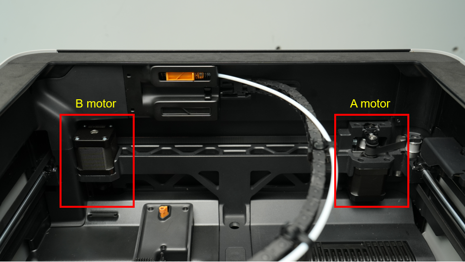
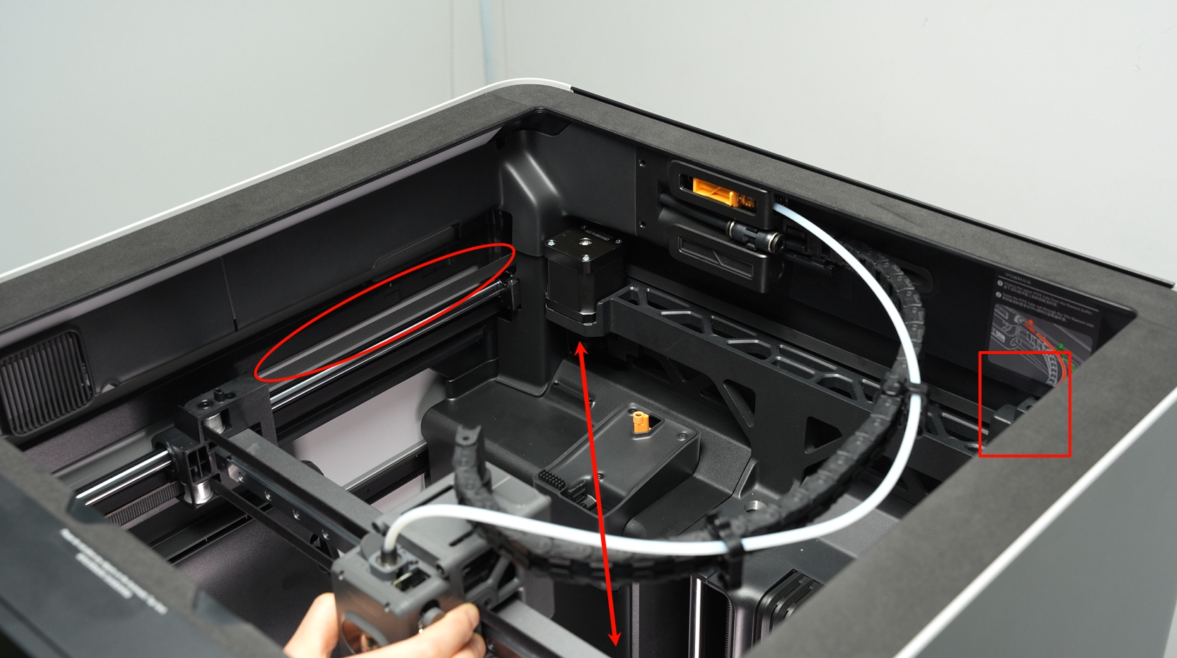
Motor A and Motor B independently control two sets of belts in the CoreXY system. As shown in the animated image below, when the left-side Motor B operates alone, it drives only the lower belt to move, causing the tool head to move diagonally at a 45° angle.
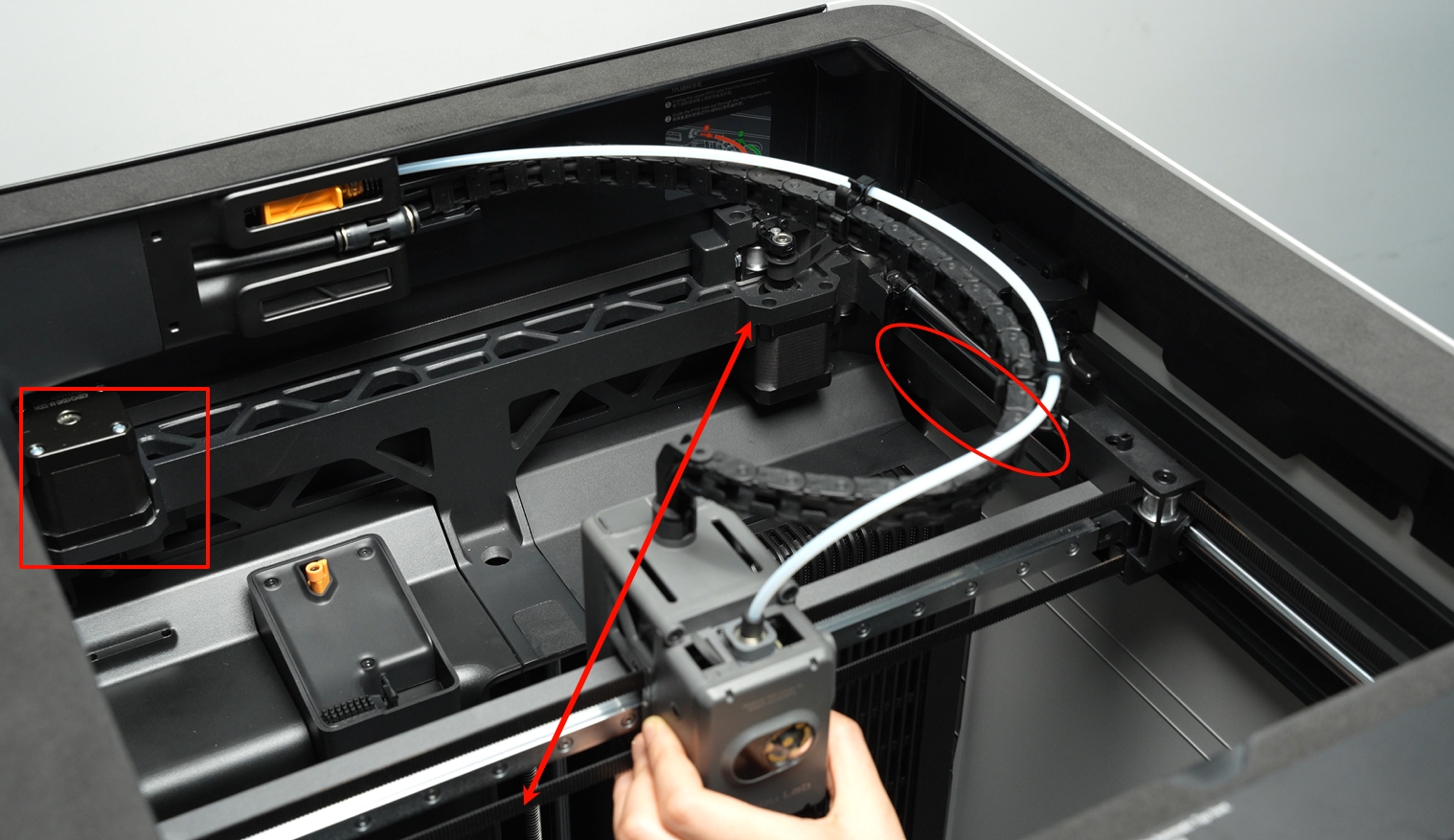
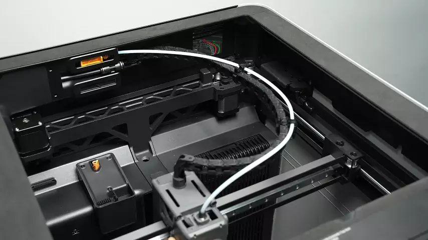
Similarly, when the right-side Motor A operates alone, it drives the upper belt to move, causing the tool head to move diagonally in the opposite 45° direction.
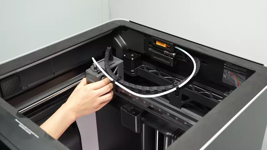
Compared to traditional Cartesian 3D printers, the H2S’s CoreXY motion system offers faster printing speeds. This is because the moving parts in a CoreXY setup are lighter, which reduces inertia and allows the tool head to accelerate and change direction more quickly. That reduced weight is a key factor in achieving high-speed, high-quality prints.
For a deeper dive into how the CoreXY motion system works, you can explore this link.
¶ Z Axis
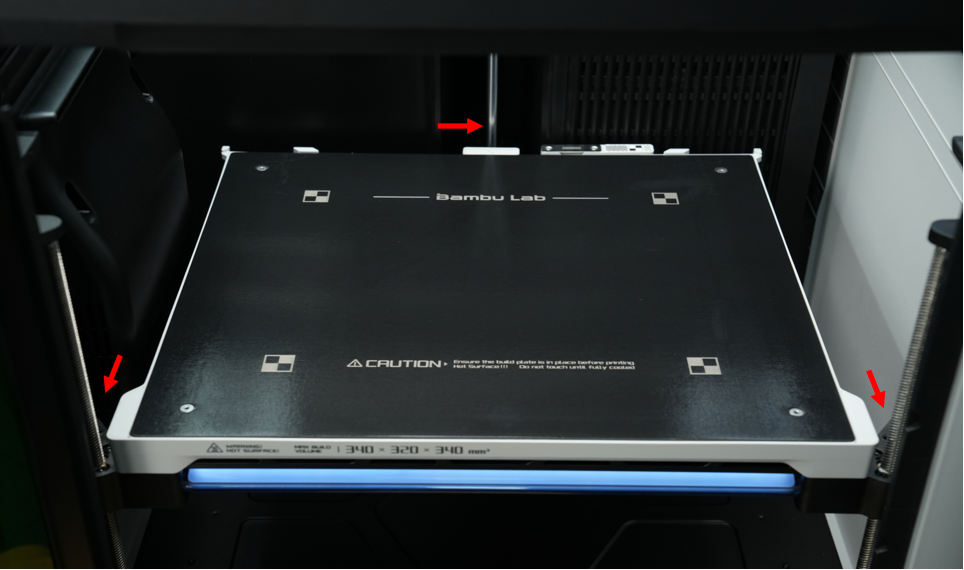
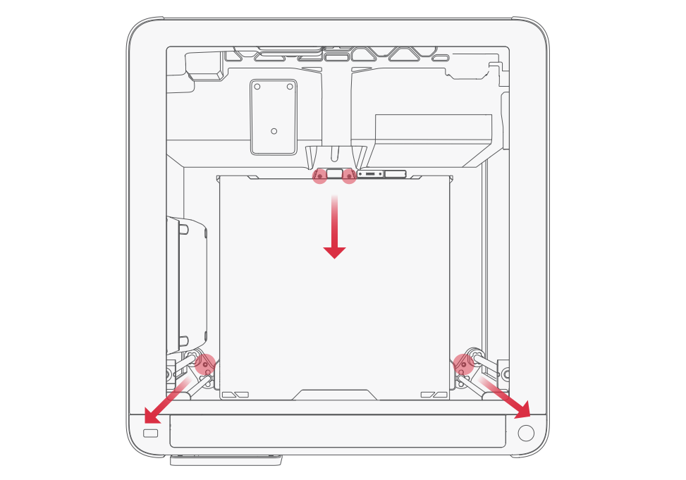
The printer’s Z-axis is driven by three lead screws, all linked to a single Z stepper motor through a belt. This setup ensures stable and even vertical movement of the build platform also known as the Heatbed.
When shipped, the H2S is already leveled at the factory. Before your first print, you only need to remove the four screws that secure the Z-axis to the base. Keep these screws in a safe place, as you will need them again if you ever disassemble the Z-axis for maintenance or transport the printer.
 |
 |
|---|
¶ Printer Enclosure
The H2S printer is available in two variants: the Standard Version and the Laser Version.
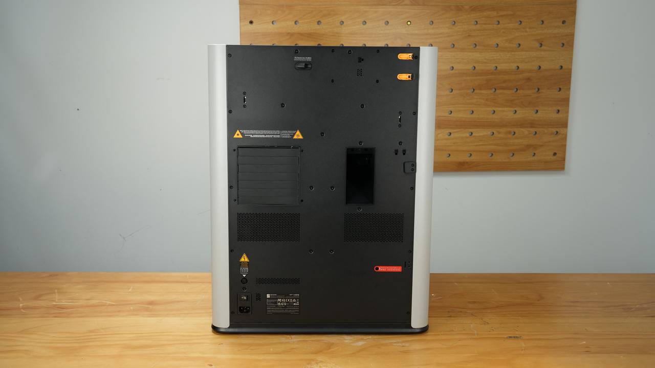
The Laser Version includes a laser protection panel by default, while the Standard Version uses regular panels. If you want to add a laser module to the Standard Version, you will need an upcoming upgrade kit, which includes a green polycarbonate (PC) front door and a black top protective cover. Without these safety components installed, the printer will automatically disable the laser function.
The H2S also has a door-opening detection system for both the front door and top cover.
- If the laser module is installed and a door is opened, the printer immediately shows a red error message and pauses the job for safety.
- If no laser module is in use, the printer displays an orange “door open” warning in the HMS (Health Monitoring System) but continues printing.
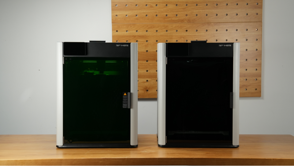
Laser Version (left) next to the Regular Version (right) |
 |
|---|---|
 |
 |
¶ Extruder
The extruder is the part of the printer that feeds filament to the nozzle, where it is melted and deposited to form the printed object.
It consists of key components such as the extruder motor and extruder gears. The extruder motor pulls filament from the spool and pushes it into the hot end, where it is heated and melted. The extruder gears grip the filament to ensure smooth and consistent feeding.
Precise control of how much filament passes through the hot end is essential for accuracy and print quality, making the extruder motor one of the most important components in the entire 3D printer.
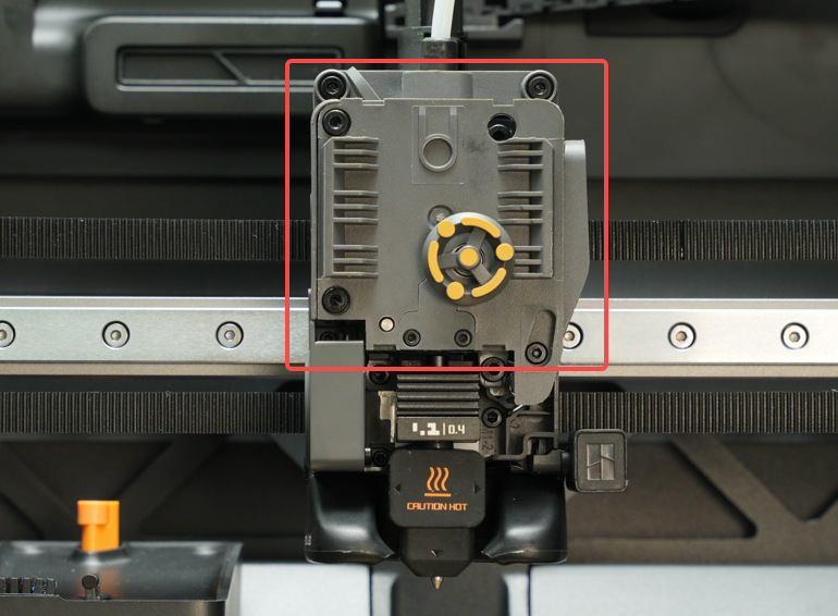
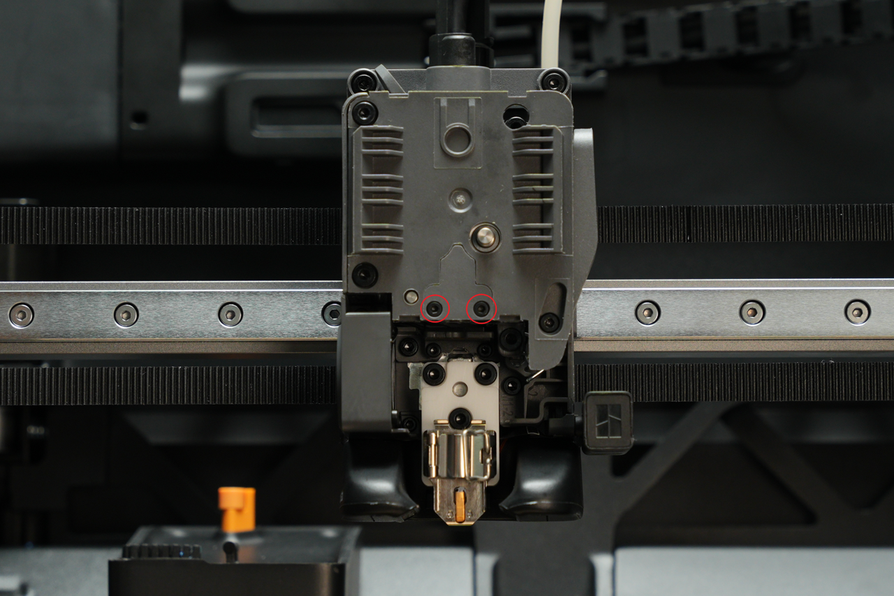
Inside the extruder, the filament guide directs the filament toward the nozzle, keeping it properly aligned during feeding. This guide can be removed if you need to check for blockages inside the extruder or just above the nozzle, making it useful for maintenance and troubleshooting.
The filament guide is an essential part of the extruder, as it ensures the filament stays constrained and feeds smoothly into the hot end. Without it, printing performance and reliability can be affected.
 |
 |
|---|
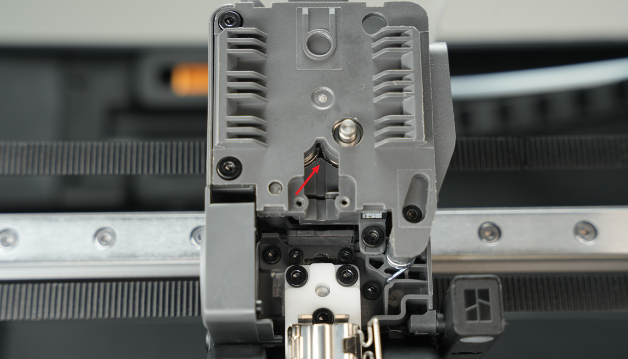
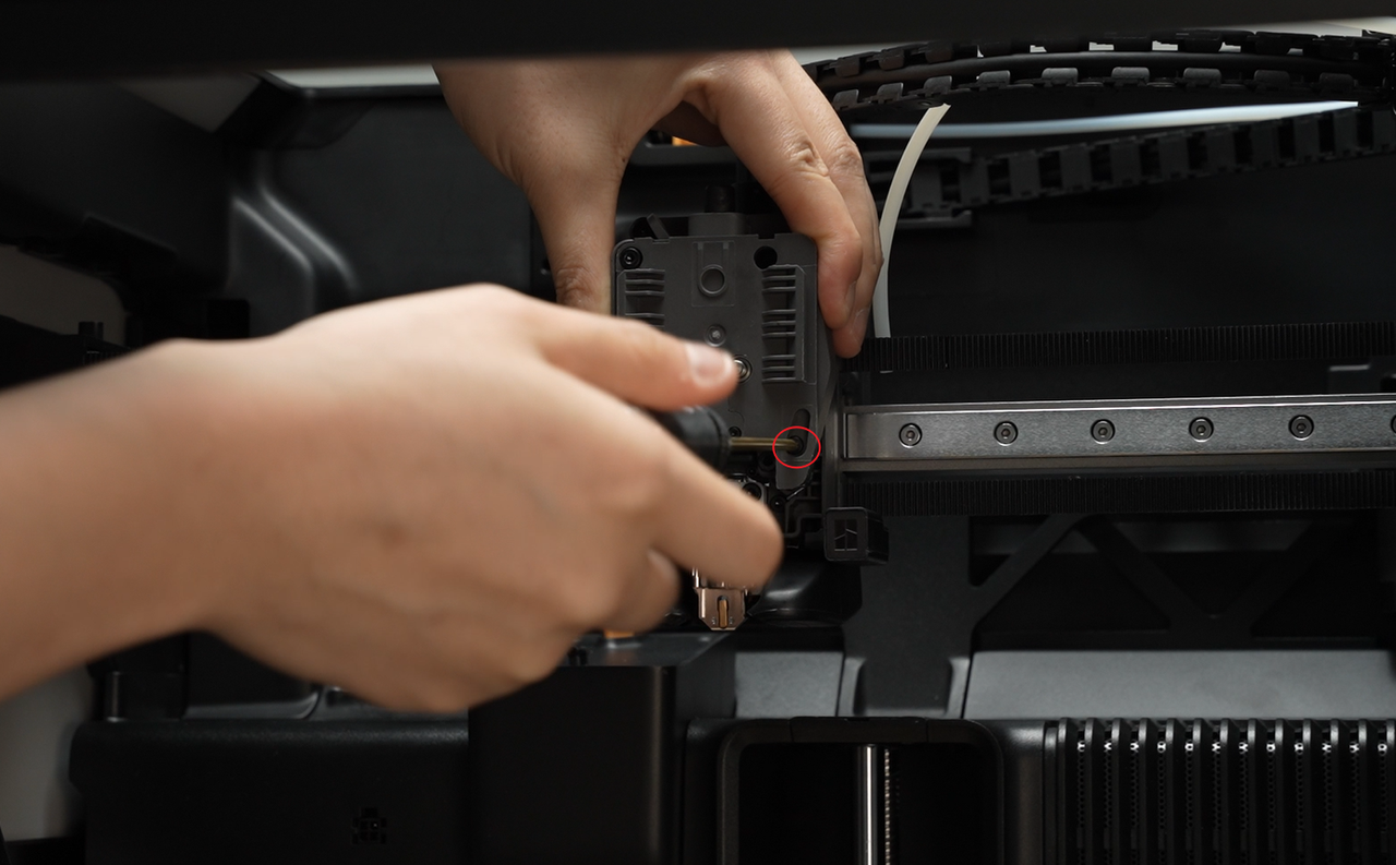
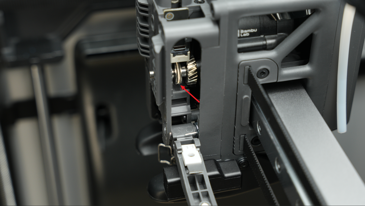
On the side of the extruder, there is a filament cutter lever. When this lever is loosened, you can access and inspect the extruder gear to check for any material buildup. If you see filament residue on the gear teeth, it can be cleaned to maintain smooth and consistent filament feeding.
 |
 |
|---|
¶ Filament Sensor
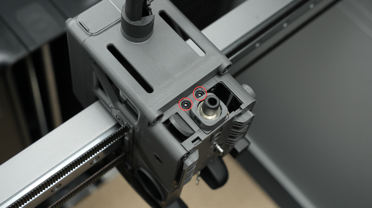
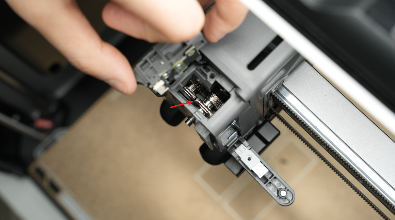
Mounted on top of the extruder, the filament sensor detects whether filament is present. If the filament runs out, the sensor signals the printer to pause and prompt a filament change.
The sensor can be removed for maintenance or troubleshooting, but care must be taken not to damage the thin ribbon cable. Removing it can help clear filament jams or allow cleaning around the extruder gears.
 |
 |
|---|
¶ Filament Cutter
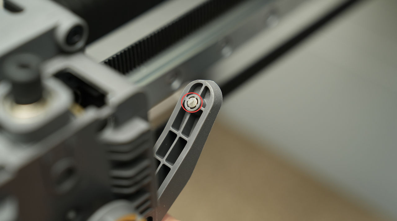
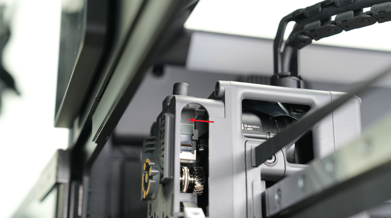
The filament cutter lever is located on the right side of the extruder assembly and controls the movement of the cutter blade. It also contains a magnet for position detection.
During the filament-cutting process, pressing the lever pushes the cutter blade to cut the filament. When combined with the filament cutter stopper on the printer frame and the AMS (Automatic Material System), this mechanism can automatically cut and replace filament, enabling multi-color or multi-material printing. After the cut is complete, the handle automatically returns to its original position.
 |
 |
|---|
The lever also has a magnet aligned horizontally with a hall sensor inside the tool head. This allows the printer to detect the exact position of the cutter handle, ensuring precise and reliable operation.
¶ Filament Cutter Stopper
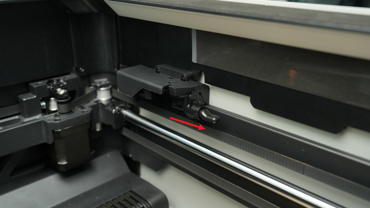
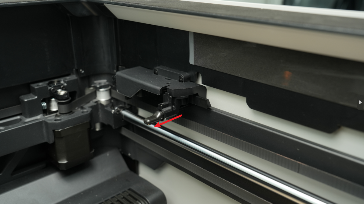
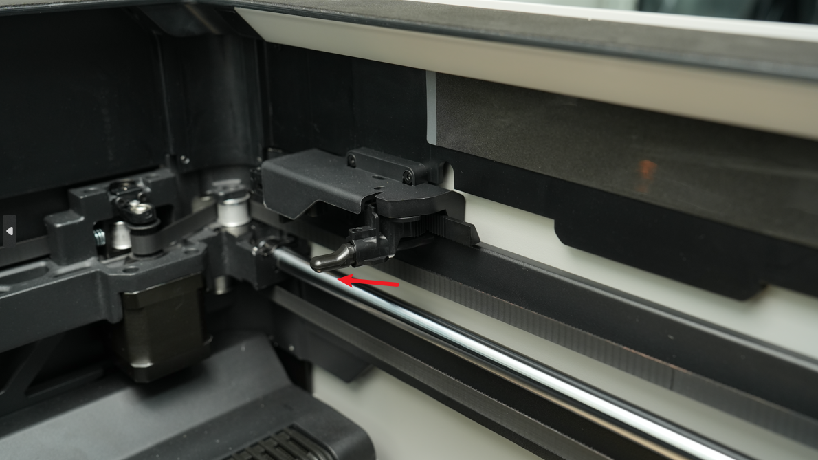
The H2S features a collapsible filament cutter stopper on the right side, which the filament cutter lever presses against to perform the cutting action.
During operation, the stopper can move between three positions:
- Zero position: Most of the time, the stopper stays in this position so it does not interfere with printing.
- Working position: When the filament needs to be cut, the stopper moves into this position to support the cutter.
- Tool head homing avoidance position: To prevent interference with the XY zero return, the stopper moves to an avoidance position when the tool head returns to zero.
Unlike the X1 and P1 printers, the H2S’s cutter ejector rod does not limit the tool head’s movement. This means the printer can use the full X and Y printing range without any special adjustments.
 |
 |
 |
|---|---|---|
| Zero position | Working position | Homing position |
¶ Hotend
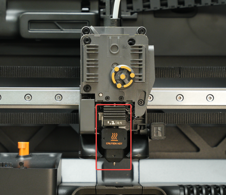
The hotend assembly is a core component of the tool head. It includes the hotend heating assembly and the nozzle, which itself contains several key parts:
- Cold end (heatsink): Keeps the upper part of the filament cool to prevent premature melting.
- Hotend: The section where the filament is heated and melted.
- Silicone sock: Provides insulation for the nozzle to maintain temperature stability and improve print quality.
The hotend can reach a maximum temperature of 350°C, allowing it to work with a wide range of filaments. It heats the filament to the specified temperature, and the melted material is deposited in thin layers to gradually build the 3D model.
Different filaments require different printing temperatures. For example:
- PLA: 210–220°C
- PPA: 300–320°C
Like the A1 series, the H2S secures the hot end heater and NTC temperature sensor directly to the heating base in the hotend heating assembly. This design simplifies the interaction with the nozzle and thanks to the tool-free quick-locking buckle, makes nozzle changes easy to do.
The H2S improves the performance of the hotend in two ways:
- Higher heating power: Increased heating power and a larger melting zone for better filament flow.
- Improved materials: The hotend heating assembly uses a zirconia ceramic insulation base and a copper heat conduction base, enhancing stiffness and reducing thermal deformation errors.
¶ Purge Chute and Nozzle Wiper
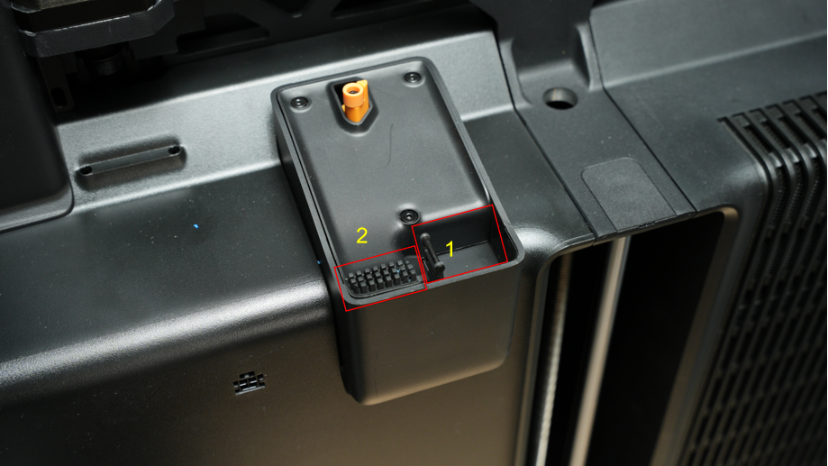
The purge chute and nozzle wiper are key components of the H2S that help remove excess filament and keep the nozzle clean.
This system includes a spring-loaded mechanism and a nozzle wiping component. During operation, the nozzle first passes over a coarse wiping strip (marked as 1) to remove larger filament residues. It then moves over a silicone strip (marked as 2) for fine cleaning, ensuring the nozzle tip is fully clean and ready for precise printing.
¶ Filament Ejection Component
This component handles the efficient disposal of large pieces of filament discarded from the nozzle during the print preparation stage. It includes a wiper strip for collecting waste and a material receiving plate for transporting it. This ensures discarded filament is properly managed, allowing smooth and uninterrupted printing. The material ejection system is important during multiple operations, including printer startup, pausing and resuming prints, loading and unloading filament, and multi-color printing.
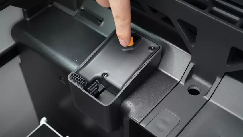
¶ Nozzle cleaning component
Used to clean the nozzle before starting a printing task. After each printing task is started, the cleaning action will be automatically executed without manual intervention.
¶ Heatbed
The heatbed is used to warm the printing surface and help printed layers stick better to the build plate. Without a heated surface, the filament might not stick well to the plate, or lead to warping.
The H2S automatically adjusts the heatbed temperature based on the filament type, with a maximum temperature of 120°C. For example:
- PLA: 35–45°C on a low-temperature print plate to prevent warping
- ABS or PC: 100–110°C to maintain layer adhesion and avoid deformation
The maximum printable area on the heatbed is 340 × 320 mm², providing a large workspace for various 3D models.
The heatbed of the H2S printer is made up of several key parts:
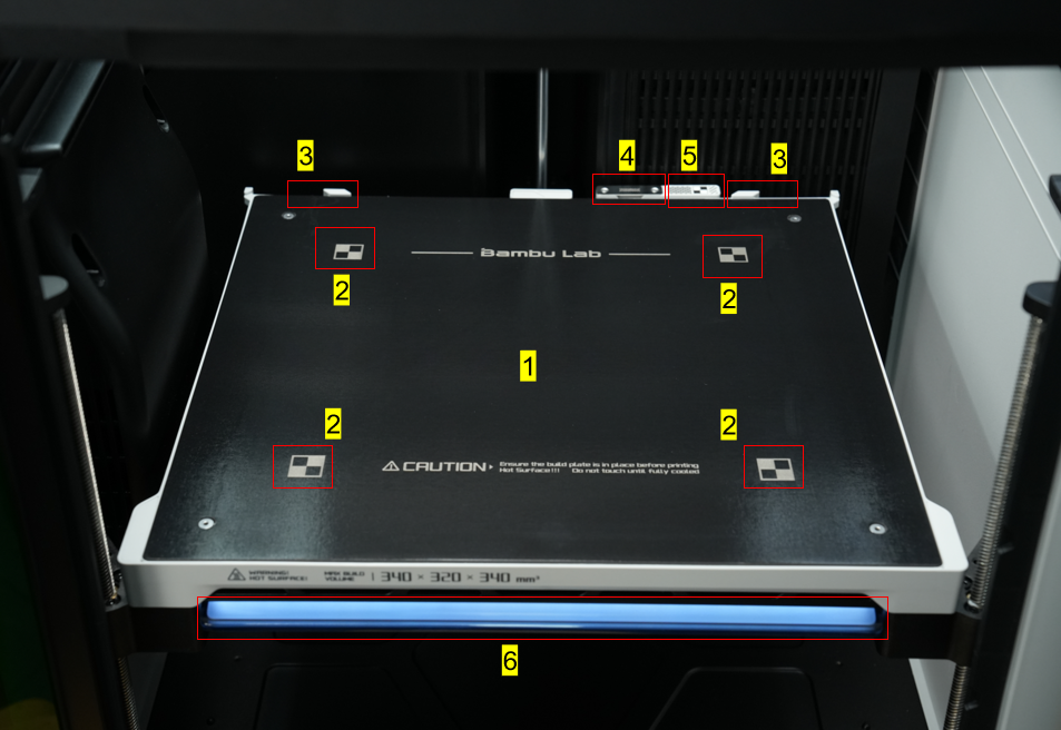
- Heating zone - The entire surface of the heatbed which will get hot. It is a magnetic surface that holds the plate in place.
- Calibration markers - used to calibrate the top-down camera and the live-view camera.
- Print Plate positioning blocks - Used to help place the build plate accurately on the heatbed.
- Nozzle Wiper Sheet - The nozzle is moved across this sheet to ensure the nozzle tip remains smooth and free from debris.
- Calibration Sticker - Used to calibrate the toolhead camera by providing a stable and consistent image.
- Status Light - the light bar underneath the print bed which shows different lighting patterns to indicate the current operating state of the printer, such as idle, preparing, printing, or error.
¶ Build Plate
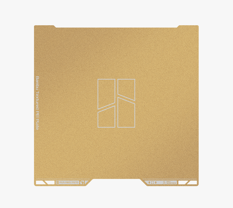
The H2S comes with a golden Textured PEI Plate, which is magnetically attached to the heatbed and serves as the primary print surface. This flexible build plate enhances print adhesion while making model removal easier. Simply bending the plate slightly allows printed objects to pop off effortlessly.
¶ Cooling System and Heating System
¶ Part Cooling Fan and Air Duct
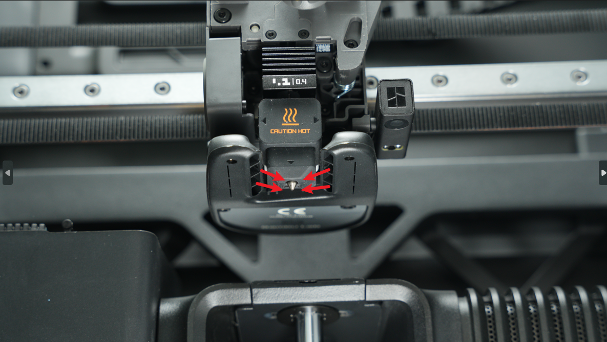
Fast and high-quality printing requires effective cooling of the printed layers. The H2S is equipped with a custom 5015 centrifugal fan and a dedicated air duct. The part cooling fan blows air through the duct, directing it precisely to the area near the nozzle. This targeted airflow rapidly cools the freshly deposited filament, helping to improve layer adhesion, prevent warping, and maintain overall print quality.
¶ Hotend Fan and Air Duct
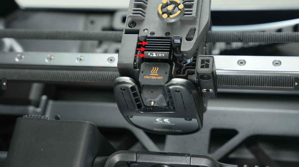
The H2S features a dedicated hotend cooling fan located on the left side of the hotend. Air from the fan is directed toward the hotend heatsink via a carefully designed air duct, helping to maintain stable temperatures in the hotend. This prevents overheating, improves print quality, and reduces the risk of nozzle clogs, ensuring consistent and reliable printing.
¶ Auxiliary component cooling fan
The H2S includes an auxiliary cooling fan to provide additional airflow for better print quality. While the main part cooling fan handles most printing tasks, small or intricate features may not cool quickly enough, which can cause deformation or weak layer adhesion.
The auxiliary fan creates a controlled airflow over freshly printed layers, helping them solidify evenly. This improves reduces sagging, improves overhangs and is especially useful when printing at high speeds or with materials that require precise cooling, such as PLA.
¶ Chamber Intake Vent
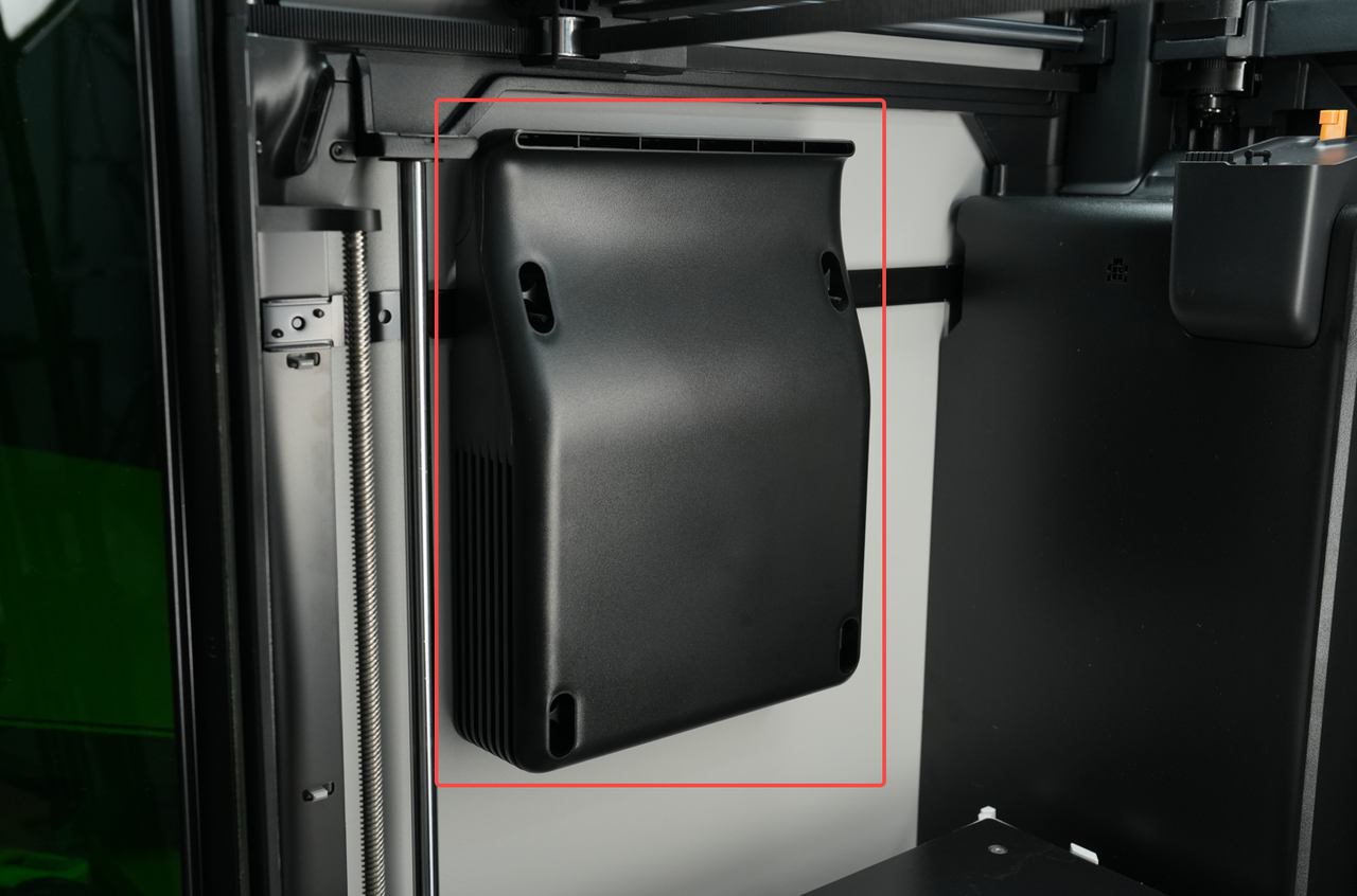
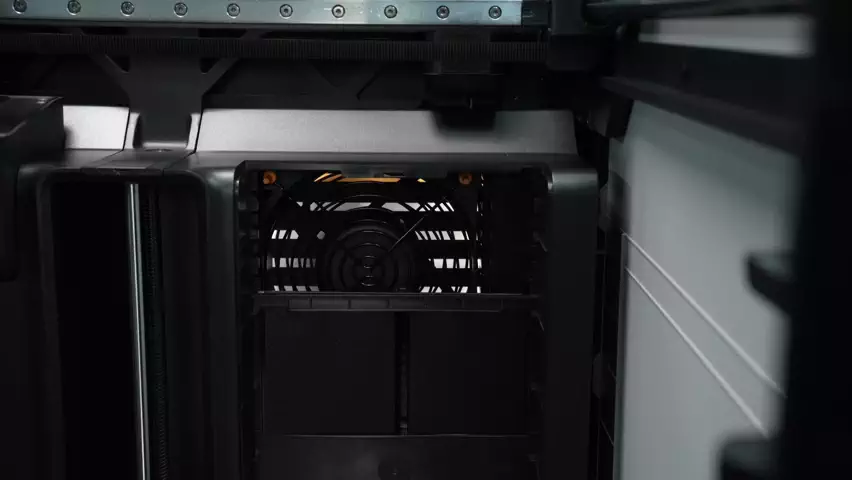
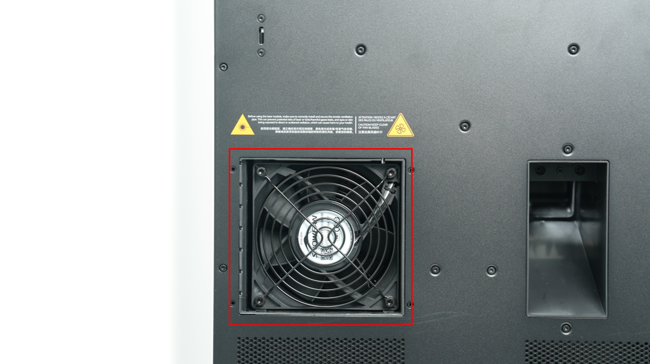
The automatic chamber intake vent is located on the top of the printer at the front. It is automatically controlled to allow cool outside air to be pulled into the chamber when the exhaust fan is pushing it out the exhaust vent.
When the H2S printer is idle or printing without chamber heating enabled, it enters cooling mode to manage internal temperatures.
- In cooling mode, the chamber filter cover remains open.
- The exhaust grille and chamber intake vent open in coordination with the chamber’s exhaust fan, allowing air to circulate between the printer enclosure and the outside environment. This helps reduce the internal temperature.
To balance cooling efficiency with noise levels, the exhaust fan automatically adjusts its speed: it increases as the chamber temperature rises during printing and decreases to around 30% when the chamber is cool and cooling demand is low.
 |
 |
|---|
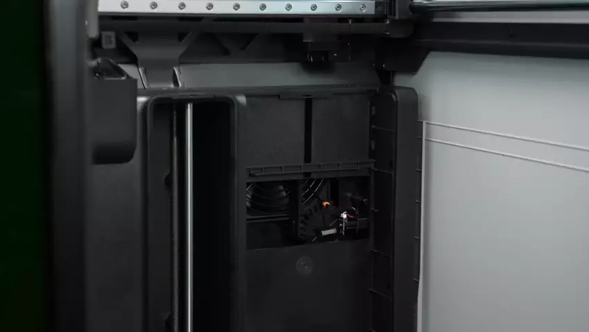
The chamber intake vent and exhaust grille serve two main functions:
- Chamber temperature control: During 3D printing, the system automatically opens, closes, and adjusts ventilation based on the filament type and chamber temperature. This ensures precise temperature management inside the printer.
- Laser operation safety and filtration: When using the laser module, the system provides sufficient intake airflow to help exhaust gases and particles pass through the filter before being released outside. The damper’s opening angle is carefully designed to maintain airflow while preventing direct laser radiation from escaping, minimizing potential harm to users.
¶ Chamber Heater
When the H2S heats the printer chamber, the system enters chamber temperature maintenance mode. During this mode:
- The automatic exhaust grille and chamber intake vent close to retain heat.
- During the initial heating phase, the filter switching damper opens to increase airflow and accelerate temperature rise.
- Once the target temperature is reached, the filter switching damper closes to maintain effective filtration while keeping the chamber temperature stable.
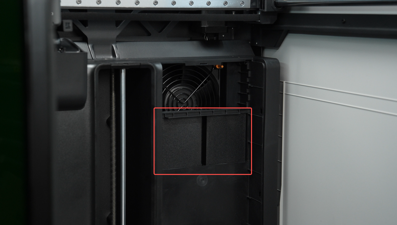
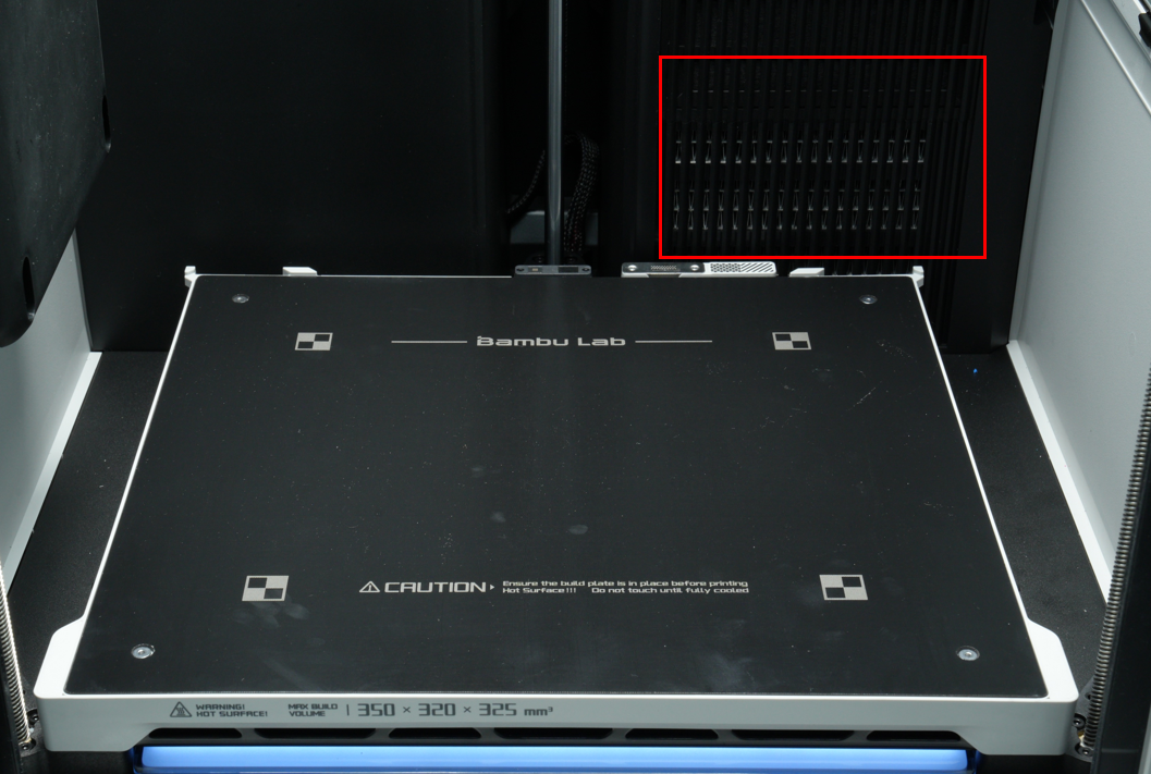
When the chamber temperature is set (either on the printer screen, in Bambu Studio, or via Bambu Handy) or when the chamber heating is specified in a sliced file, the printer enters heating mode.
Note that the heater may not immediately be active, depending on conditions.
Once the chamber temperature is activated, the system switches to chamber temperature maintenance mode.
The chamber heater consists of a PTC heating element and a circulation fan. During heating:
- The PTC element operates at full power.
- The circulation fan runs at maximum speed to distribute heat evenly.
After the chamber reaches the target temperature, the fan continues running at the same speed, while the PTC reduces power to maintain a stable chamber temperature.
¶ Filament Buffer
 |
 |
|---|
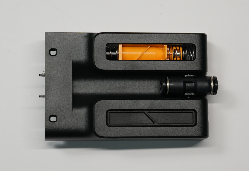
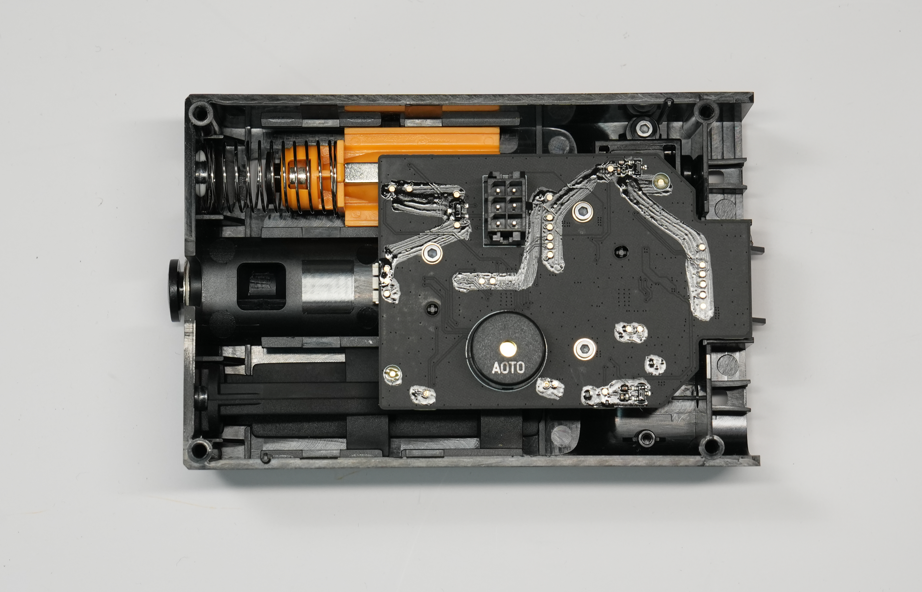
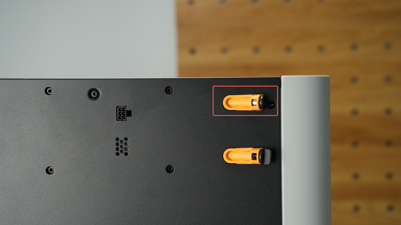
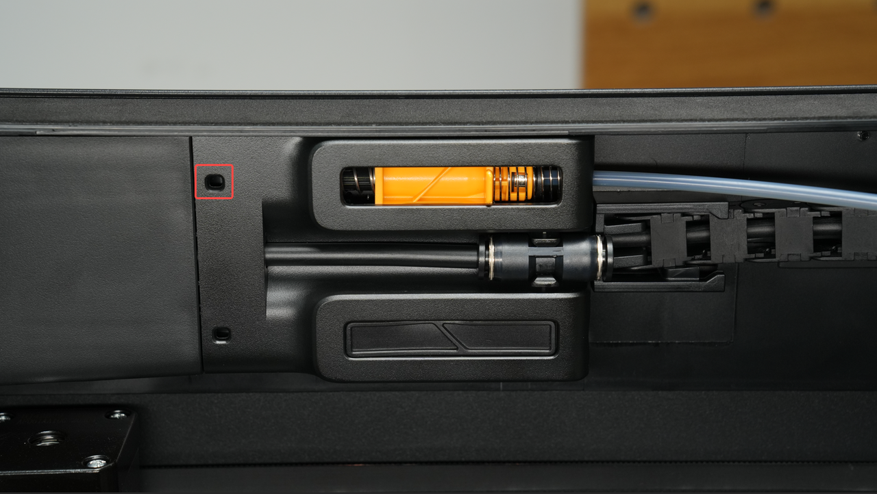
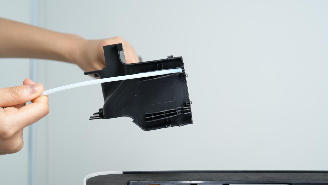
The filament buffer on the H2S is similar in design to that of the H2D. Since the H2S has a single hotend and single extrusion, it only has one filament path. To ensure smooth feeding, always use the filament path above the buffer along with the standard-length filament PTFE tube provided. This helps reduce resistance during filament feeding.
To use the buffer:
- Insert the tube through the filament coupler at the back of the printer.
- Push the tube all the way in until it reaches the end and is visible through the opening on the front of the buffer.
 |
 |
 |
|---|
The filament buffer consists of two main sections:
- Buffering section: Includes a slider*, a magnet, two springs, and a hall sensor. This section absorbs filament tension to ensure smooth feeding.
- Material detection section: Includes a magnet, a spring, and a hall sensor. This section detects whether filament is present, helping the printer monitor material flow.
¶ Buffer Section
The buffer stores a short length of filament to make feeding smoother. When the AMS pushes filament into the extruder, the filament pressure moves a slider to the right, temporarily storing some filament inside the buffer. As the extruder uses the filament, the slider moves back to the left. A sensor monitors the slider’s position and sends this information to the AMS and printer, which can then adjust the feeding speed.
The buffer also detects filament tangles. If the filament gets stuck or entangled, the slider cannot move normally. When the Hall sensor detects this unusual movement, the printer alerts the user through the HMS system, allowing them to fix the problem before it affects printing.
¶ Filament Detection Section
The H2S buffer includes a filament detection function that works with the official material tube expansion port. This allows a single hotend to connect to up to four AMS units, without needing the AMS Hub used in the X1 or P1 series. This setup simplifies multi-material printing and improves feeding reliability.
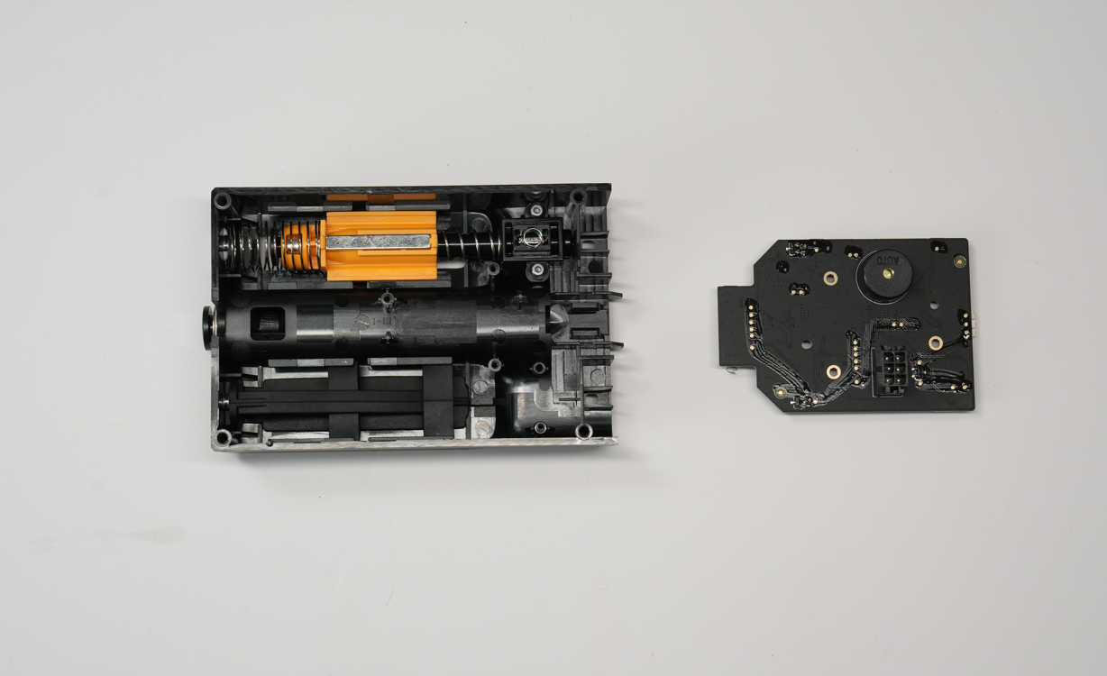
The material detection section uses a magnet and spring system along with a Hall sensor.
- No filament: The spring pushes the magnet away from the hall sensor.
- Filament present: The filament pushes the magnet toward the hall sensor.
This movement allows the printer to detect whether filament is present, ensuring smooth feeding and alerting the user if material runs out.
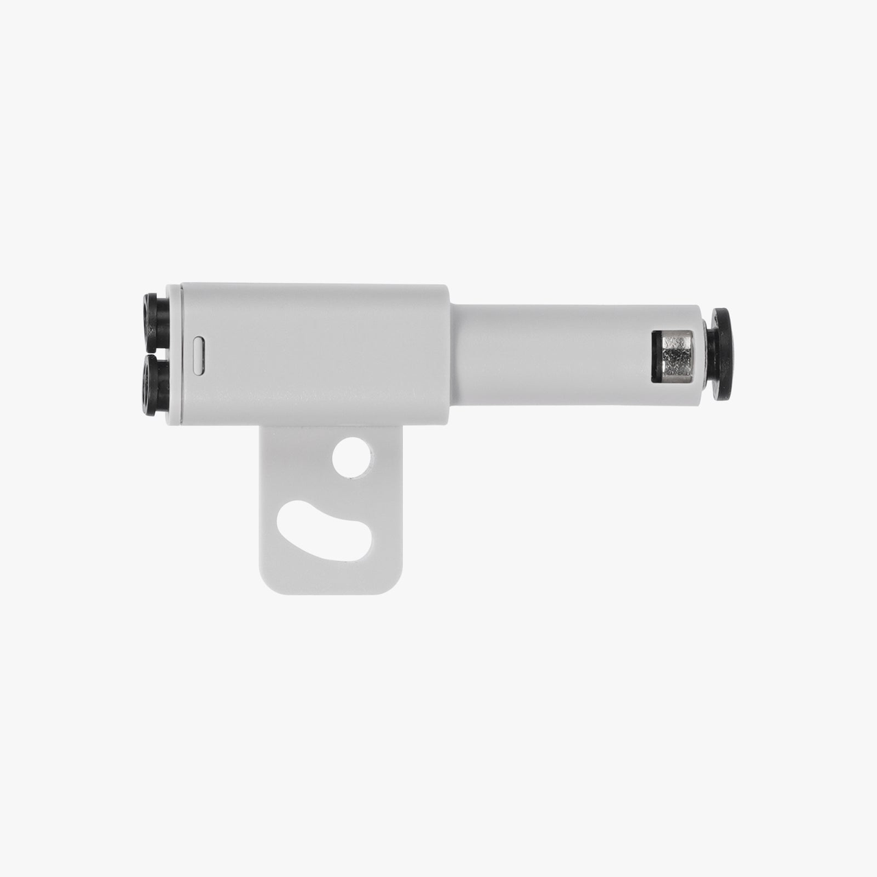 4-in-1 Filament Hub can be used to connect up to 4 AMS units
¶ Belt Tensioner
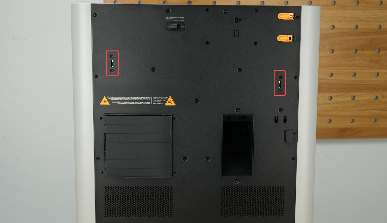
The H2S features an adjustable belt tensioner at the rear of the printer. The Belt Tension Monitor (BTM) continuously checks the tension of the belts, provides feedback to the user, and allows adjustments to maintain optimal belt performance. Proper belt tension helps ensure accurate and reliable printing.
¶ Electrical Components
The H2S contains a variety of electronic components that control its functions. Here are the most important ones:
¶ Main Control Boards
The printer has two core main control boards: one handles interactive logic, and the other controls overall machine motion.
¶ AP Logic Main Control Board
This board features a quad-core CPU and interfaces with various connected devices. It manages intelligent functions such as AI detection, flow calibration, and vibration compensation, and also handles communication between slicing software, mobile apps, and the printer.
¶ MC Motion Control Board
This board includes a dual-core M4 MCU and a single-core M7 MCU, as well as stepper drivers and connections for motion electronics. It provides:
- XYZ motion control
- Chamber and hotbed temperature control
- Chamber status monitoring (door, top cover, side panel switch, and glass type detection)
- Circulation system control (airflow and vent management)
- The MC board executes the printer’s movements and overall status after receiving the G-code stream from the AP Logic Board.
¶ USB Storage Interface
The H2S includes a USB A port supporting USB 2.0, which can be used for offline printing from a flash drive and storing time-lapse videos.
¶ Screen
The printer has a 5-inch 1280×720 touchscreen with a smooth user interface, providing a responsive and easy-to-use control experience.
¶ Toolhead Camera
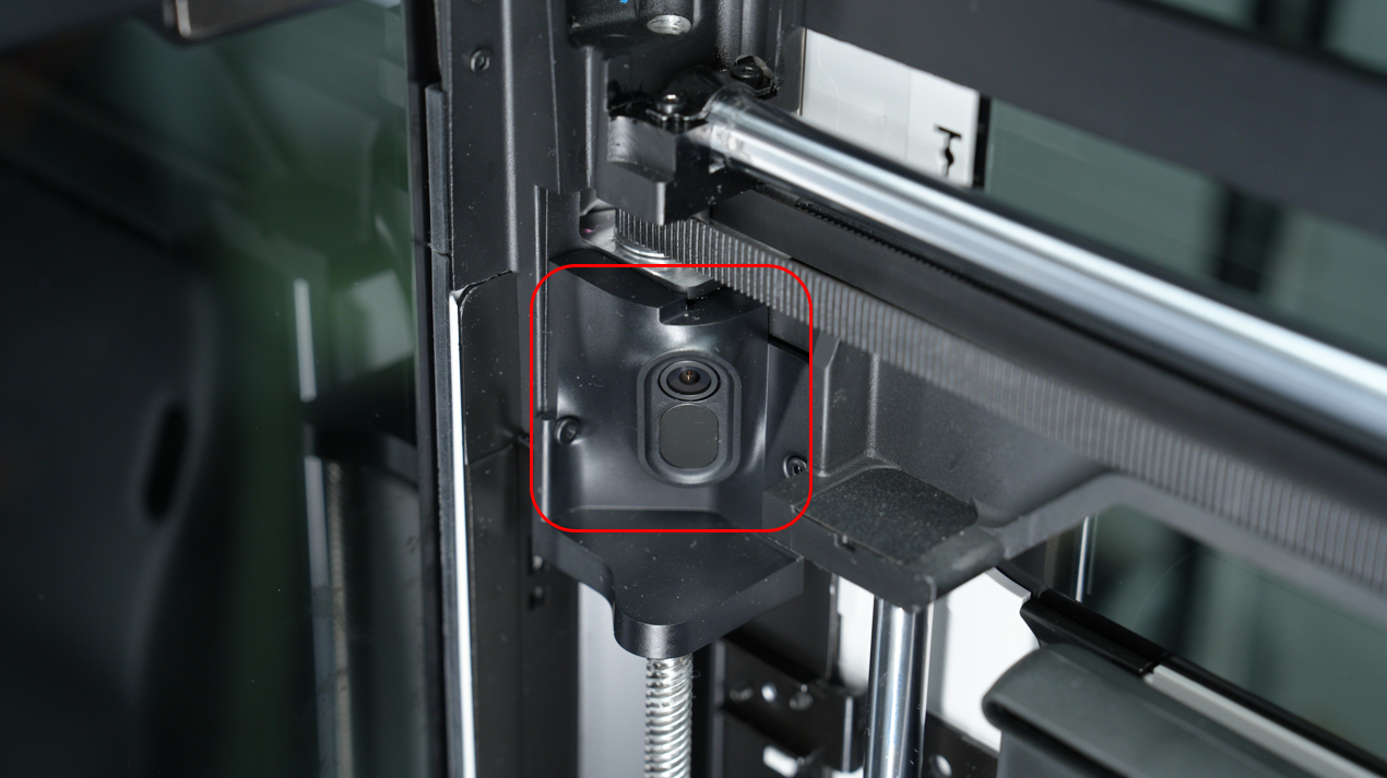
A 1600×1200 resolution camera at 30fps is built into the toolhead for motion accuracy calibration, ensuring precise printing.
¶ Live View Camera
The H2S features a live view camera with 1920×1080 resolution at 30fps. It allows users to monitor the printer chamber in real time, capture time-lapse videos, and supports AI detection functions for smarter printing management.
¶ BirdsEye View Camera (Optional)
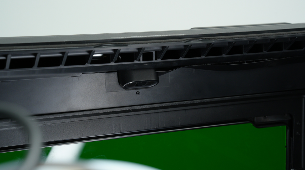
The H2S can be optionally equipped with a top-down BirdsEye camera with 3264×2448 resolution and a maximum frame rate of 15fps. This camera is designed for advanced intelligent detection and recognition, particularly in laser and die-cutting applications. It requires the laser module to be installed.
¶ LED Lighting
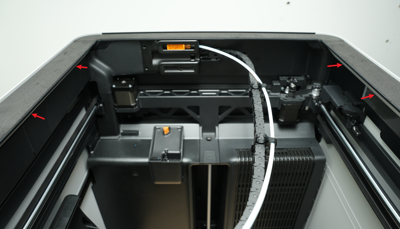
Both the left and right crossbeams of the H2S are equipped with LED light strips. These provide bright, even illumination inside the printer chamber, making it easier to monitor prints and inspect the interior.
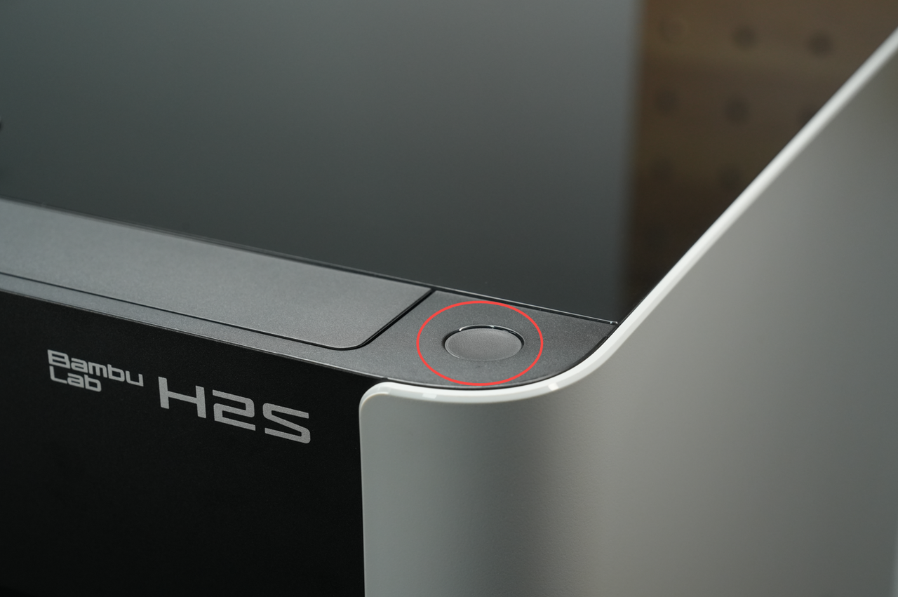
¶ Start/Pause Button
Laser tasks require manual supervision. Therefore, after sending a laser or cutting task from the pre-processing software, the operator must press the start button located at the upper right corner of the printer to begin execution. The start button also supports pausing for laser and cutting tasks, but it does not currently support pausing 3D printing tasks (pausing for 3D printing can be initiated from the screen).
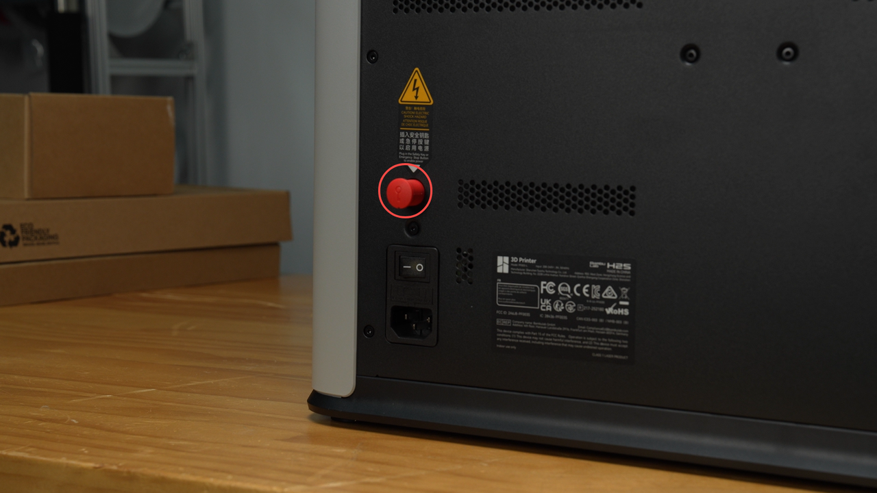
¶ Security Key
The H2S includes a safety key to comply with safety regulations.
- For 3D printing and knife cutting, the printer will only power on when the safety key is inserted.
- For laser operations, an emergency stop button with a safety key must be used.
If the printer does not power on after connecting the power supply and turning on the switch, always check that the safety key is properly inserted.
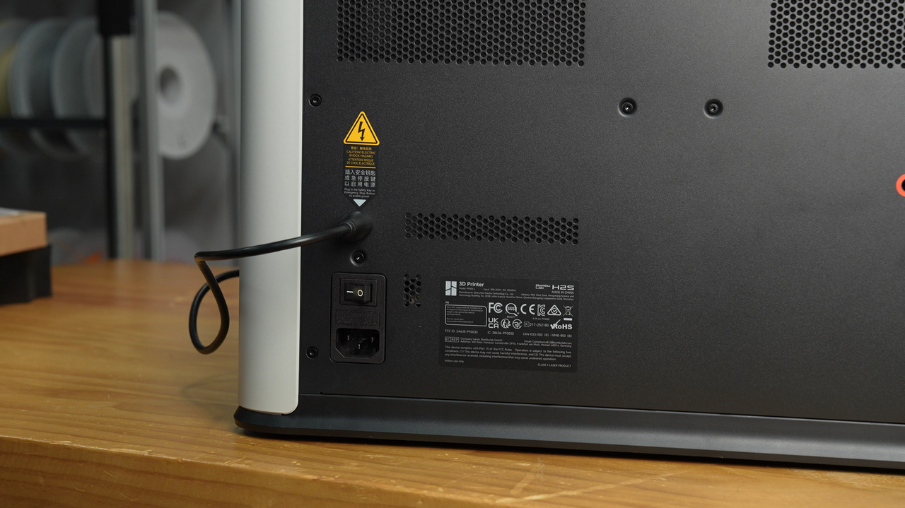
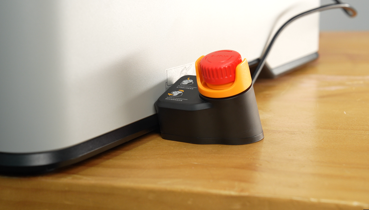
¶ Emergency Stop Button (optional)
Emergency Stop Button (optional)
The emergency stop button is optional for 3D printing and knife cutting but is required for laser operations. To use the laser function, the emergency stop button (with its safety key) must be installed, and its plug inserted into the safety key slot on the back of the printer.
Laser tasks require continuous on-site supervision. In an emergency, pressing the emergency stop button immediately cuts power to the printer, allowing the operator to handle urgent situations safely.
Note: Both the back of the printer and the emergency stop button come with pre-installed safety keys. Always store the safety key from the back of the printer safely after removing it.
 |
 |
|---|
¶ End Notes
We hope the detailed guide provided has been helpful and informative.
If this guide does not solve your problem, please submit a technical ticket, we will answer your questions and provide assistance.
If you have any suggestions or feedback on this Wiki, please leave a message in the comment area. Thank you for your support and attention!