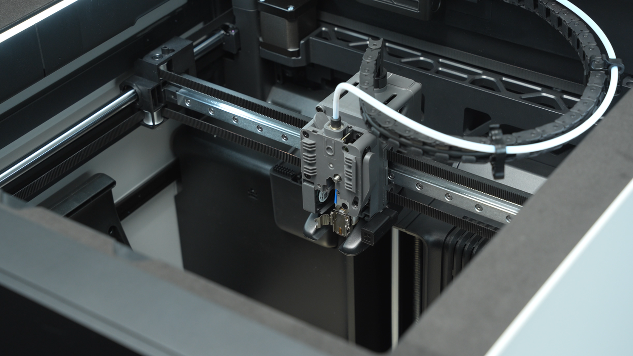
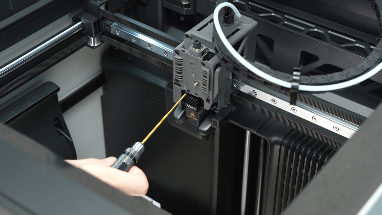
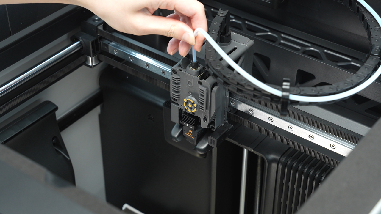
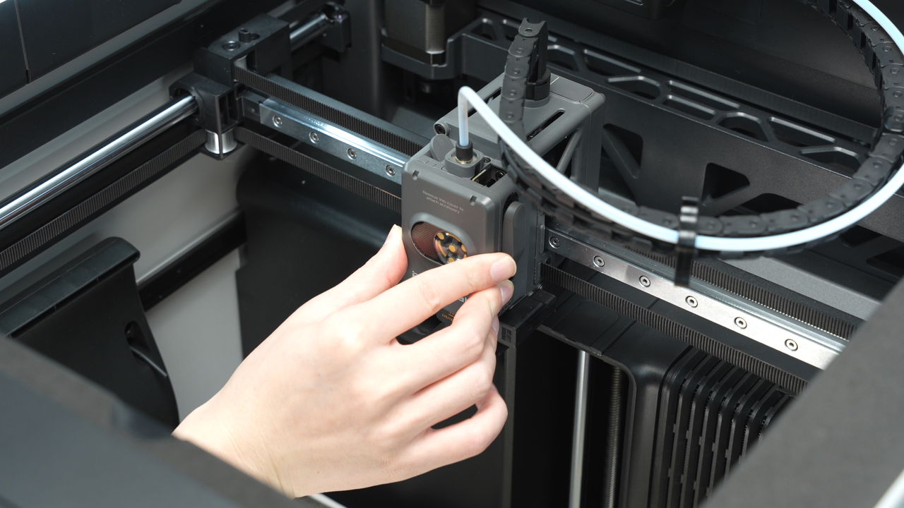
Please be sure to follow the disassembly sequence outlined in this article strictly. Especially before removing the cover of the extruder, make sure to first remove the extruder filament sensor (handle with care to avoid pulling too hard), as failure to do so may result in the wiring of the sensor broken.
The printer reports extruder motor overload, air printing, or no error but it can be observed that the hotend is unable to extrude filament.
- Extruder assembly
- Hotend
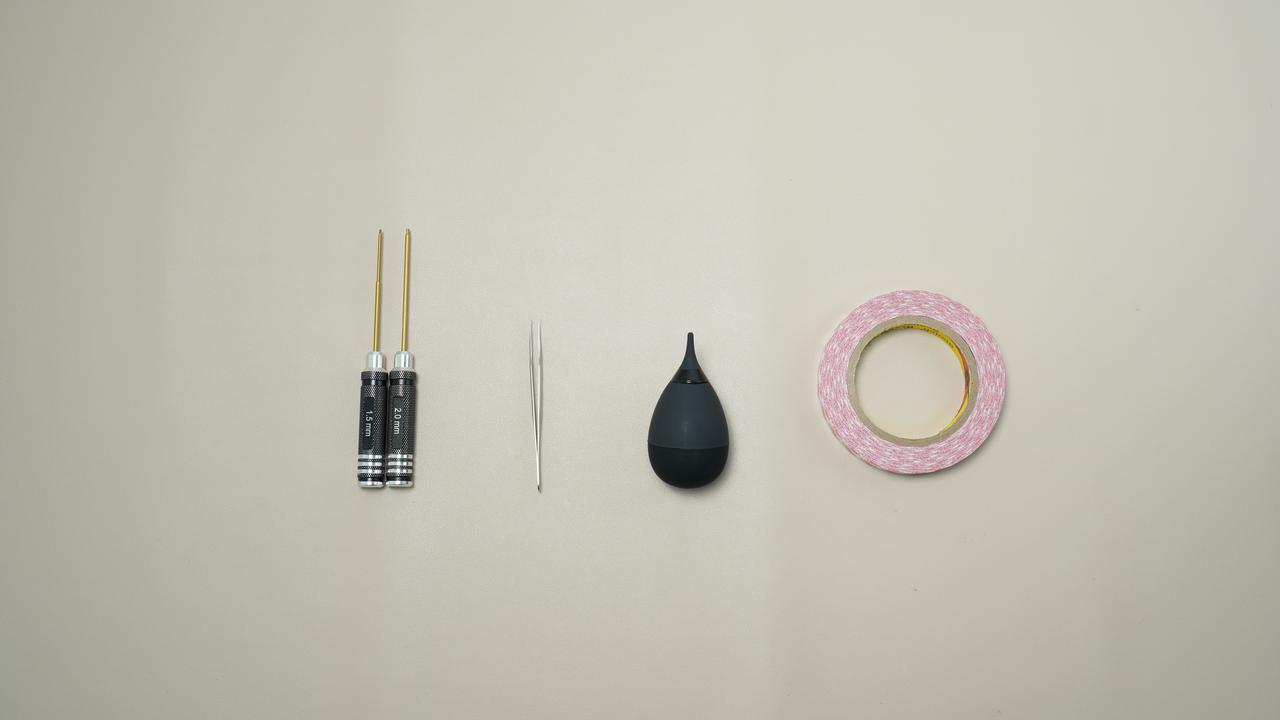
- H1.5 or H2.0 Allen key
- Tweezer and Blowing Balloon
- Double-sided tape
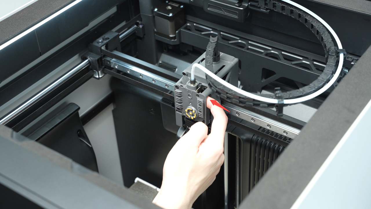
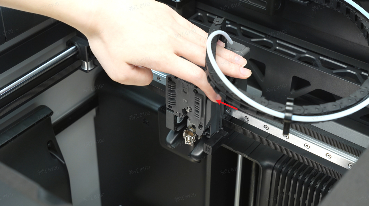
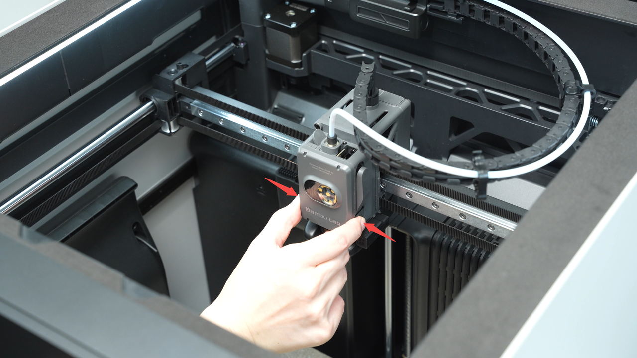
Apply force from the side to press on the front cover of the toolhead, unlocking and removing it.
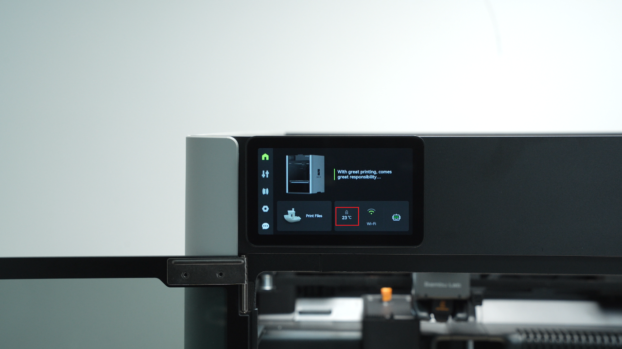
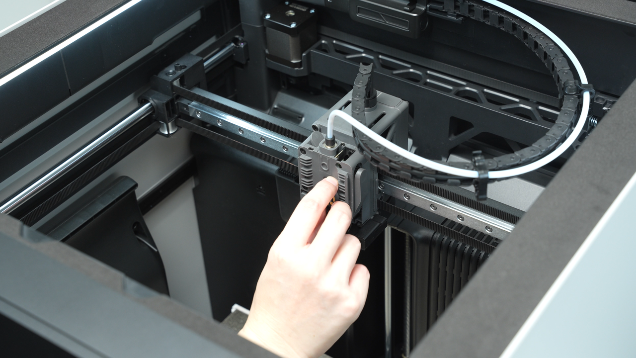
Ensure the hot end temperature is at room temperature. Press the cutter to cut the filament.
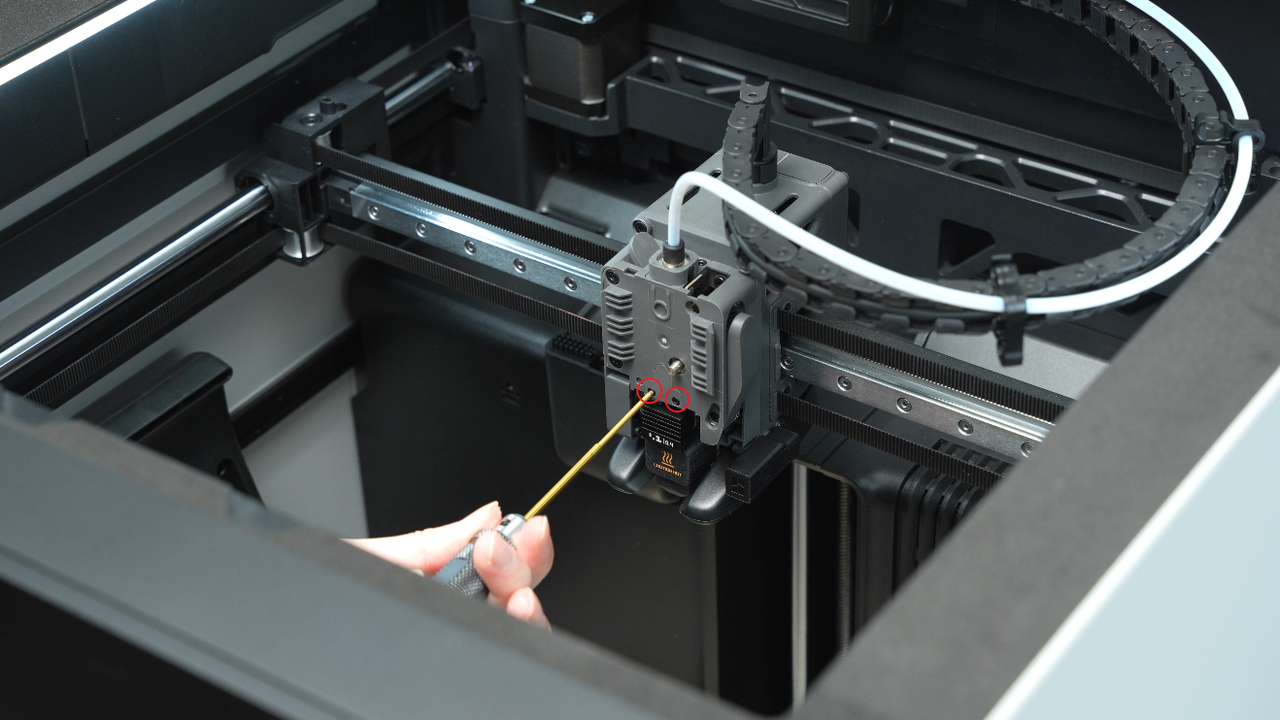
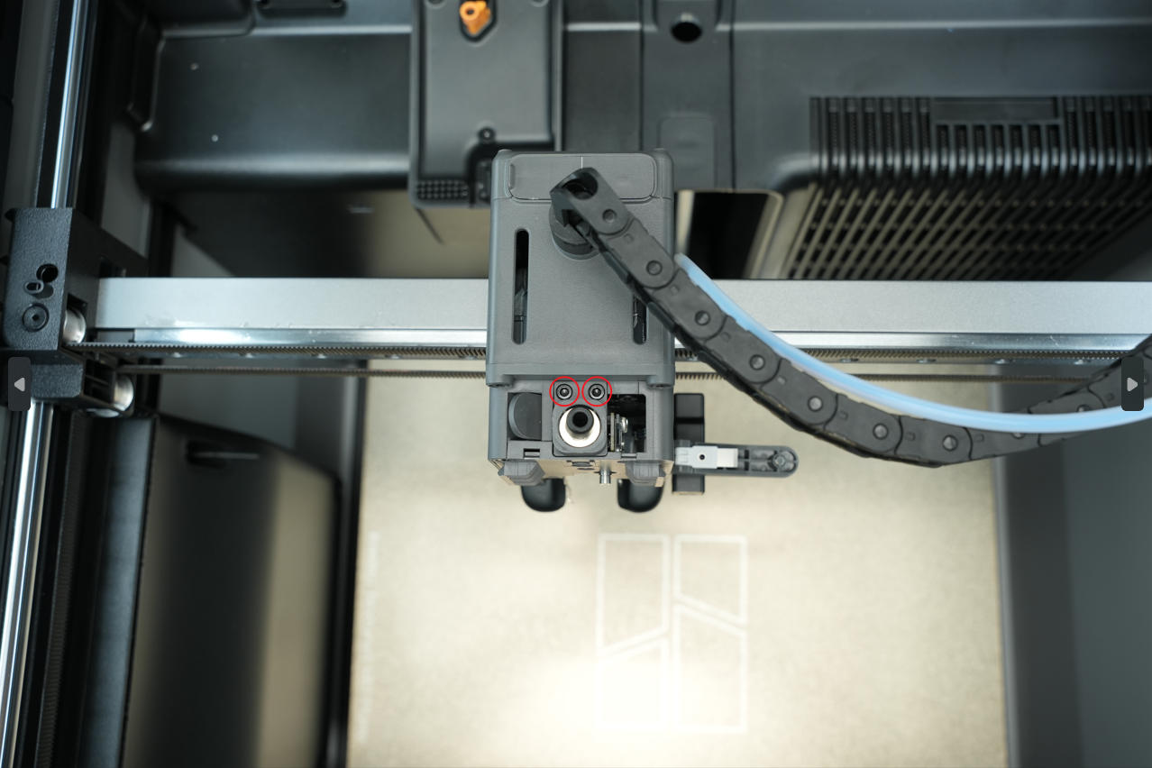
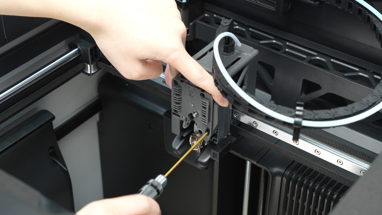
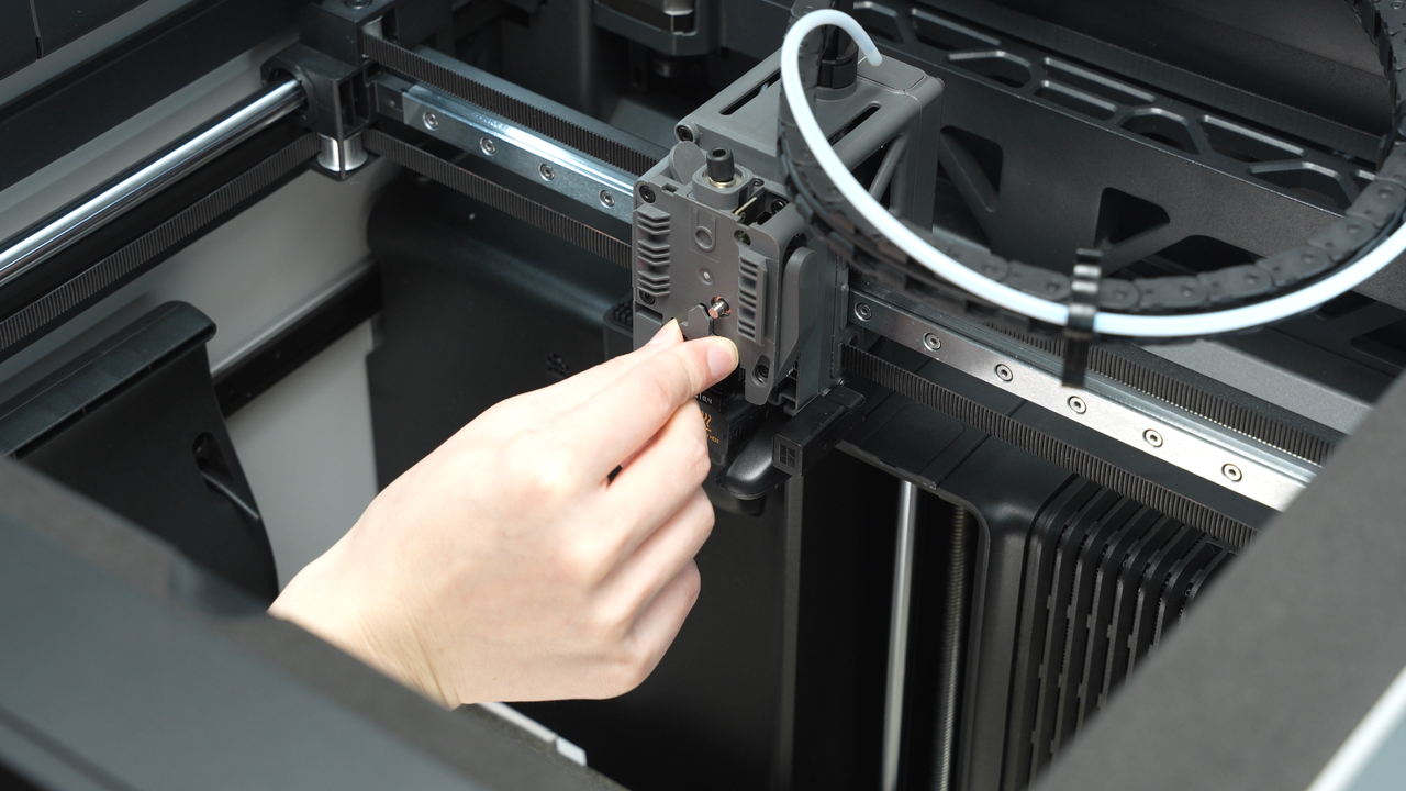
Remove the rotary wheel. Use a H1.5 hex key to remove the two screws and take off the filament guide block.
Under normal circumstances, the hot end can be removed directly without disassembling the filament guide block. However, we choose to remove the clamp first to facilitate subsequent cleaning in this wiki.
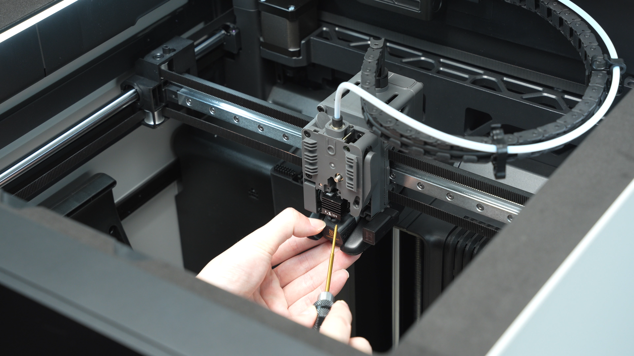
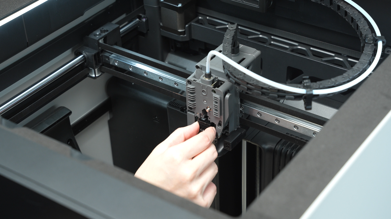
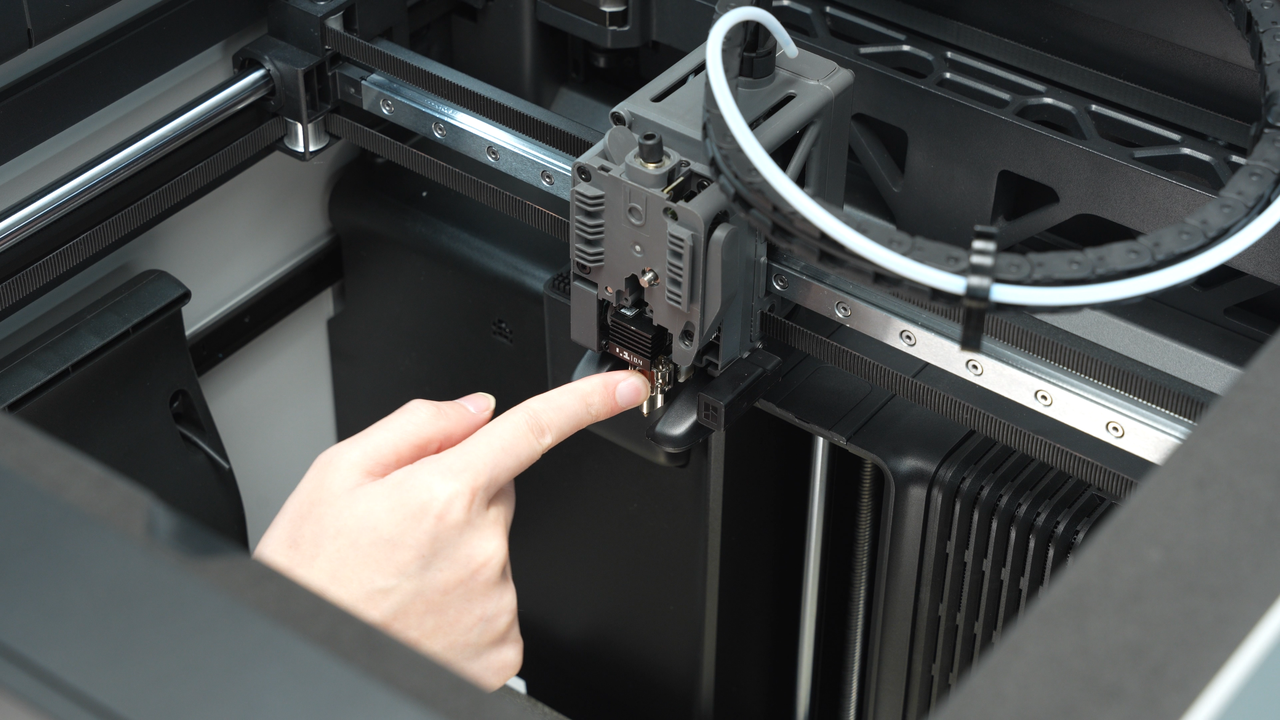
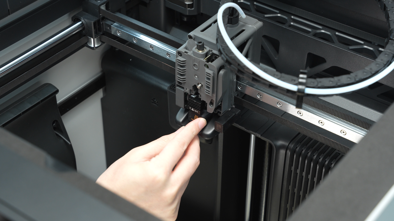
Remove the silicone sock, release the hot end latch, then grasp the heat sink by hand to remove the hot end.
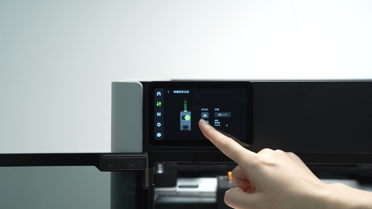
After removing the hot end, feed the filament into the extruder and attempt manual extrusion by pressing the extrusion button on the screen. If the printer prompts "Please heat the nozzle to above 170°C", you can select "Don't remind me".
If the filament is extruding smoothly, it likely indicates a clog in the hot end. We recommend referring to H2S Hotend Unclogging Procedure for guidance on clearing the hot end.
If the filament cannot be extruded properly or retracts, it indicates a clog or jam in the extruder, requiring disassembly for cleaning. Please proceed to step 3.
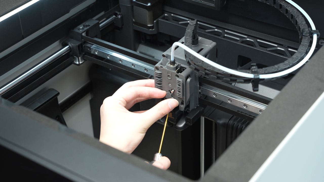
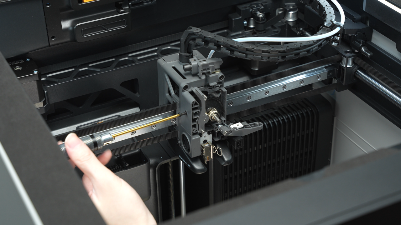
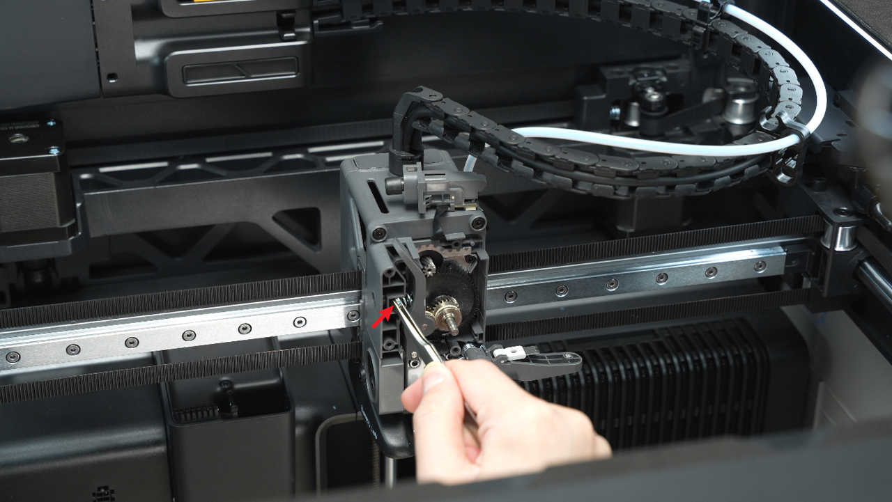
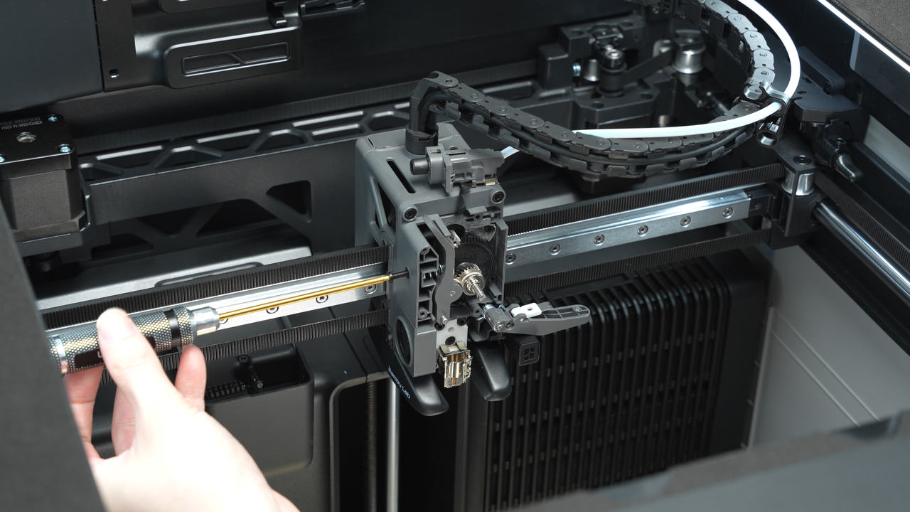
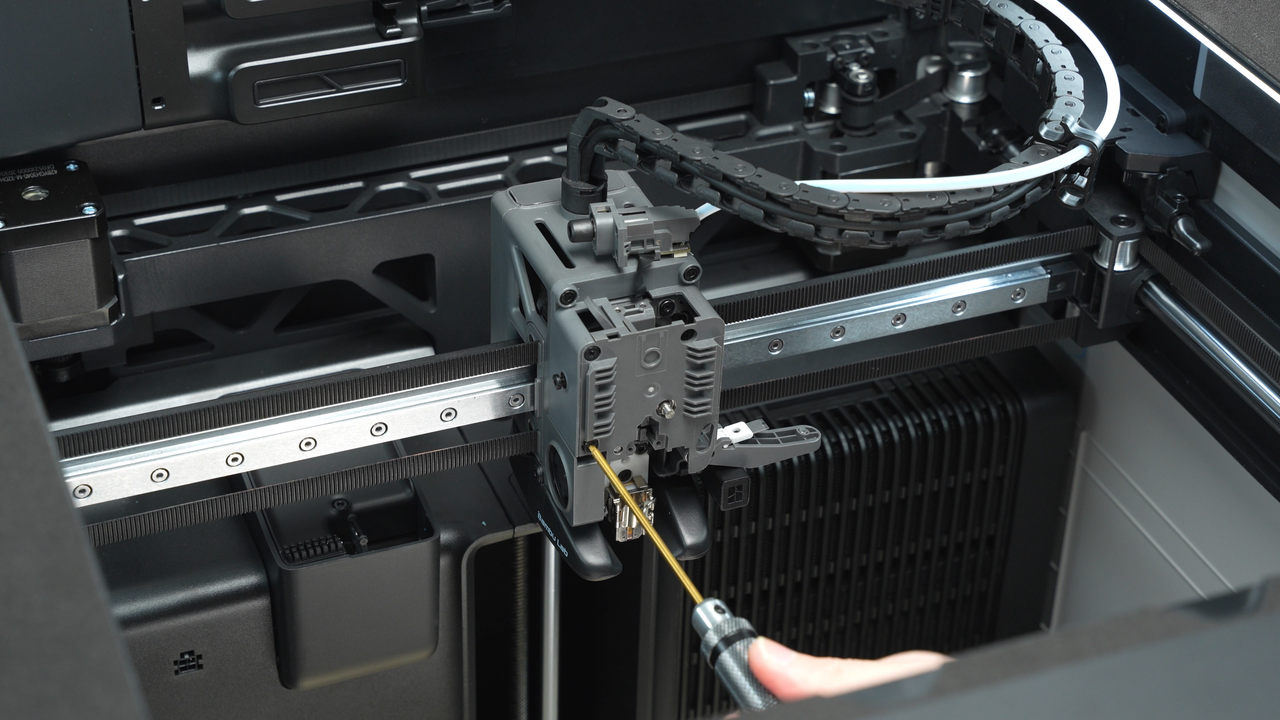
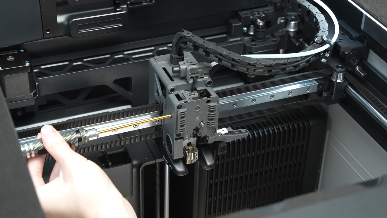
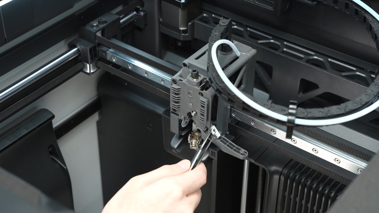
Use a H2.0 hex key to remove the cutter screw and loosen the cutter handle. This allows for cleaning from the side of the extruder.
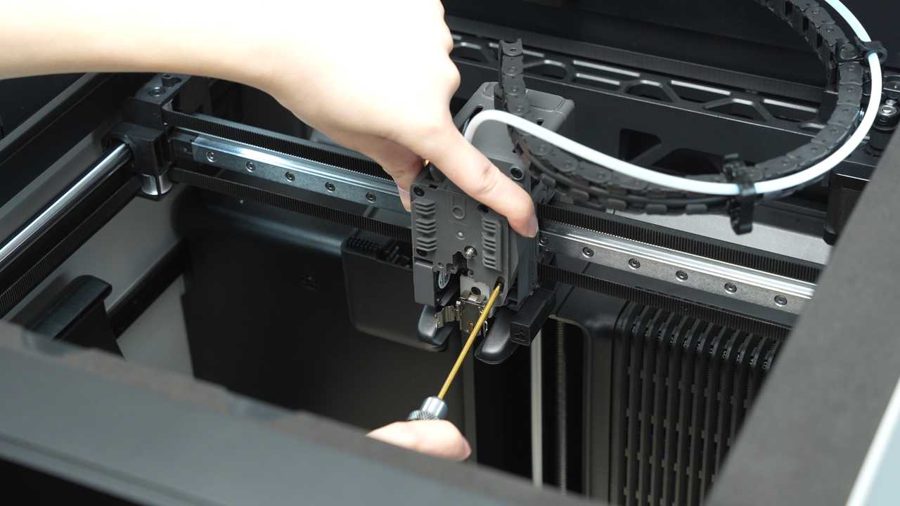
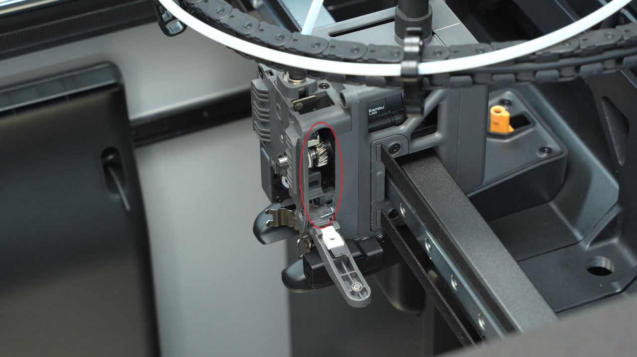
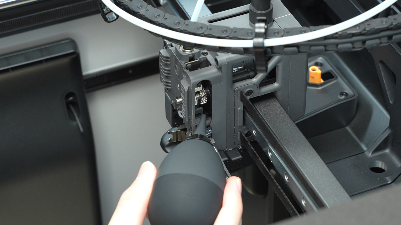
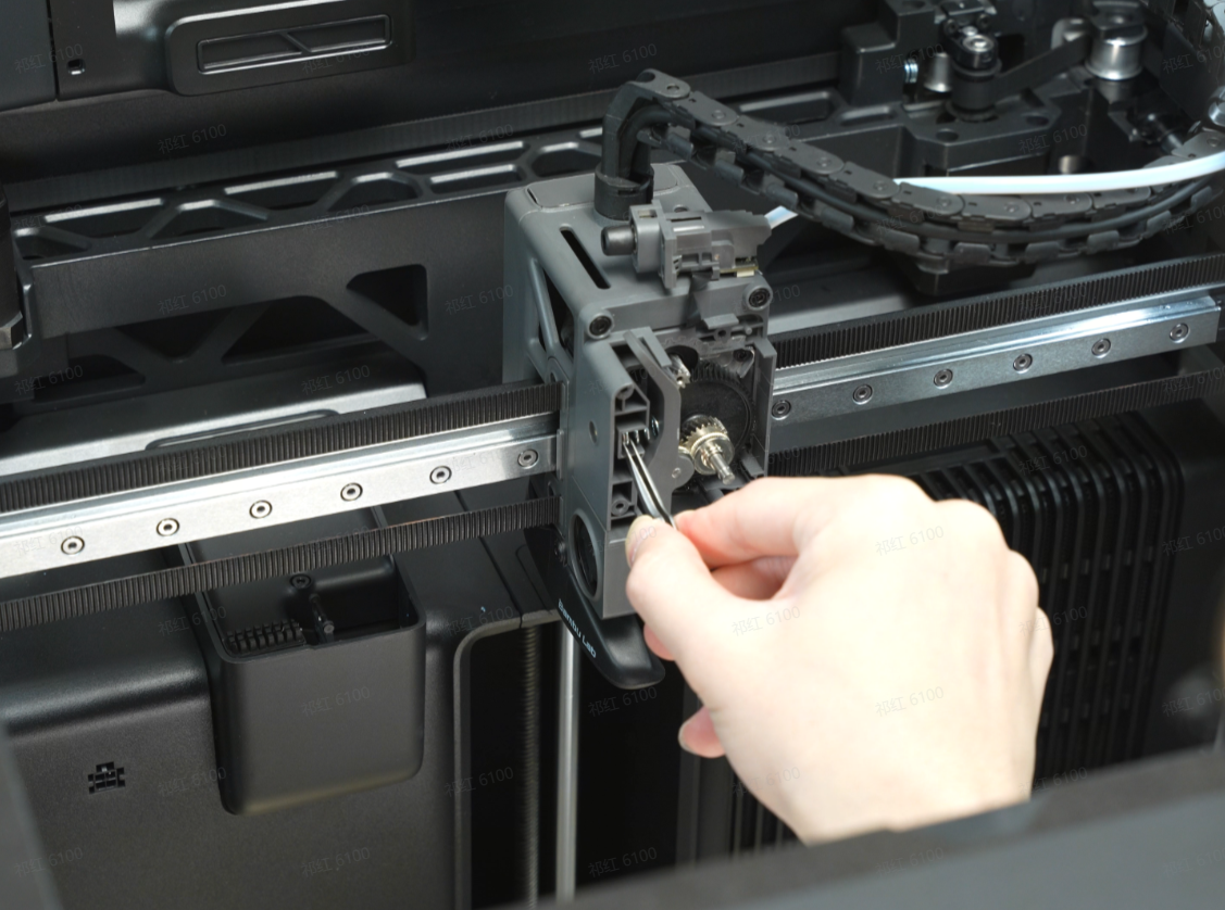
Use a tweezer or an air blower to clean the internal debris and residue from the indicated locations. In a powered-off state, manually rotate the black gear clockwise for cleaning.
If cleaning the extruder according to the above steps does not resolve the issue of improper extrusion, you may need to disassemble the extruder and remove the extruder assembly for a more thorough cleaning.
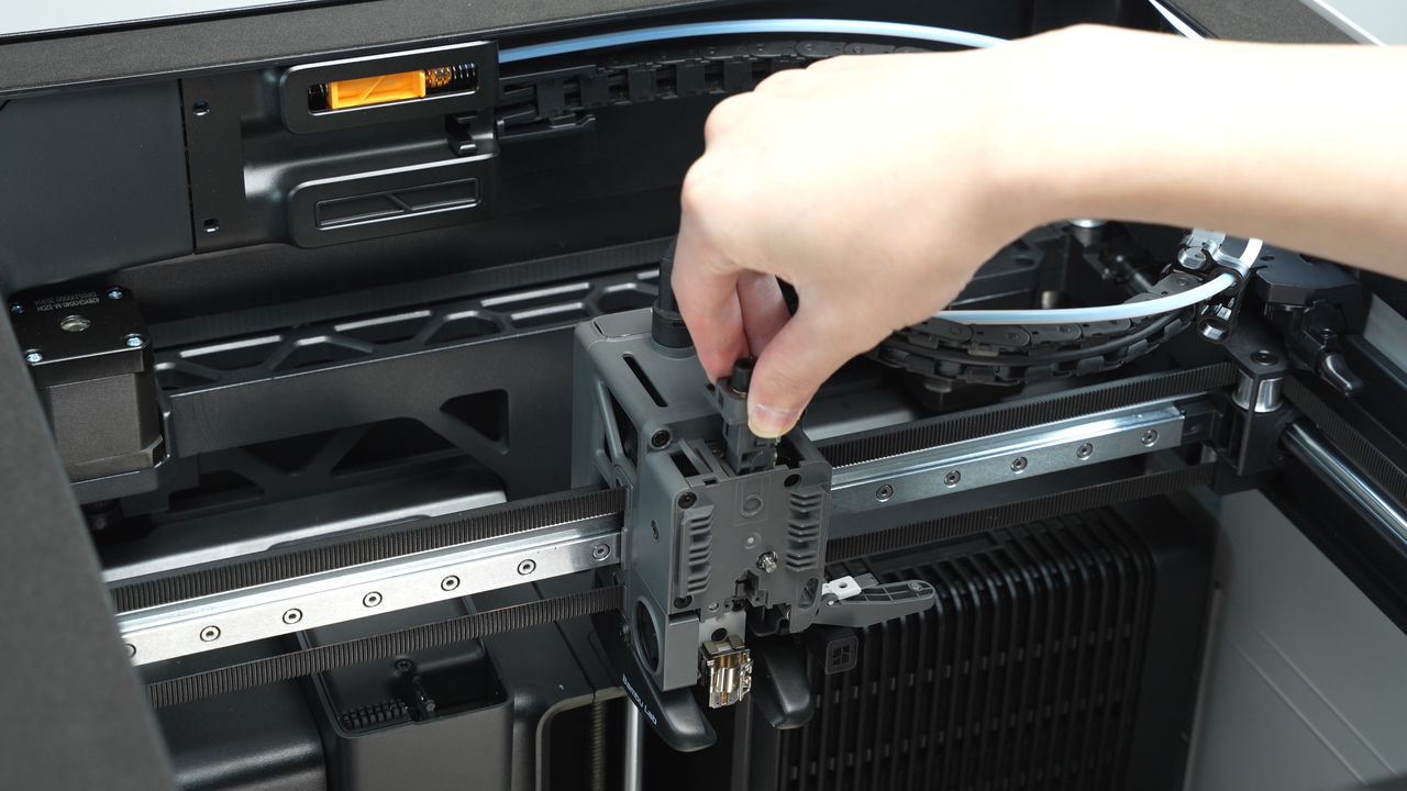
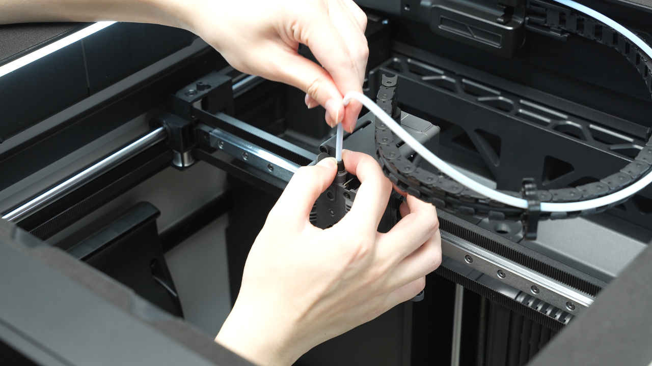
Press the black ring to disconnect the PTFE tube.
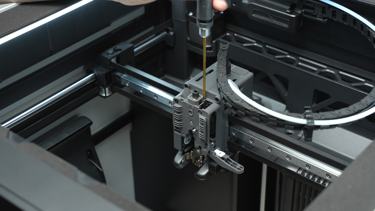
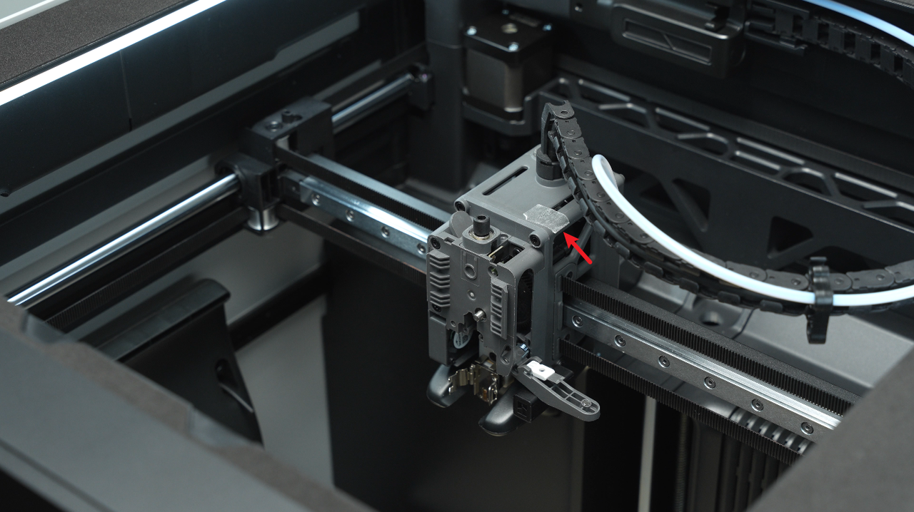
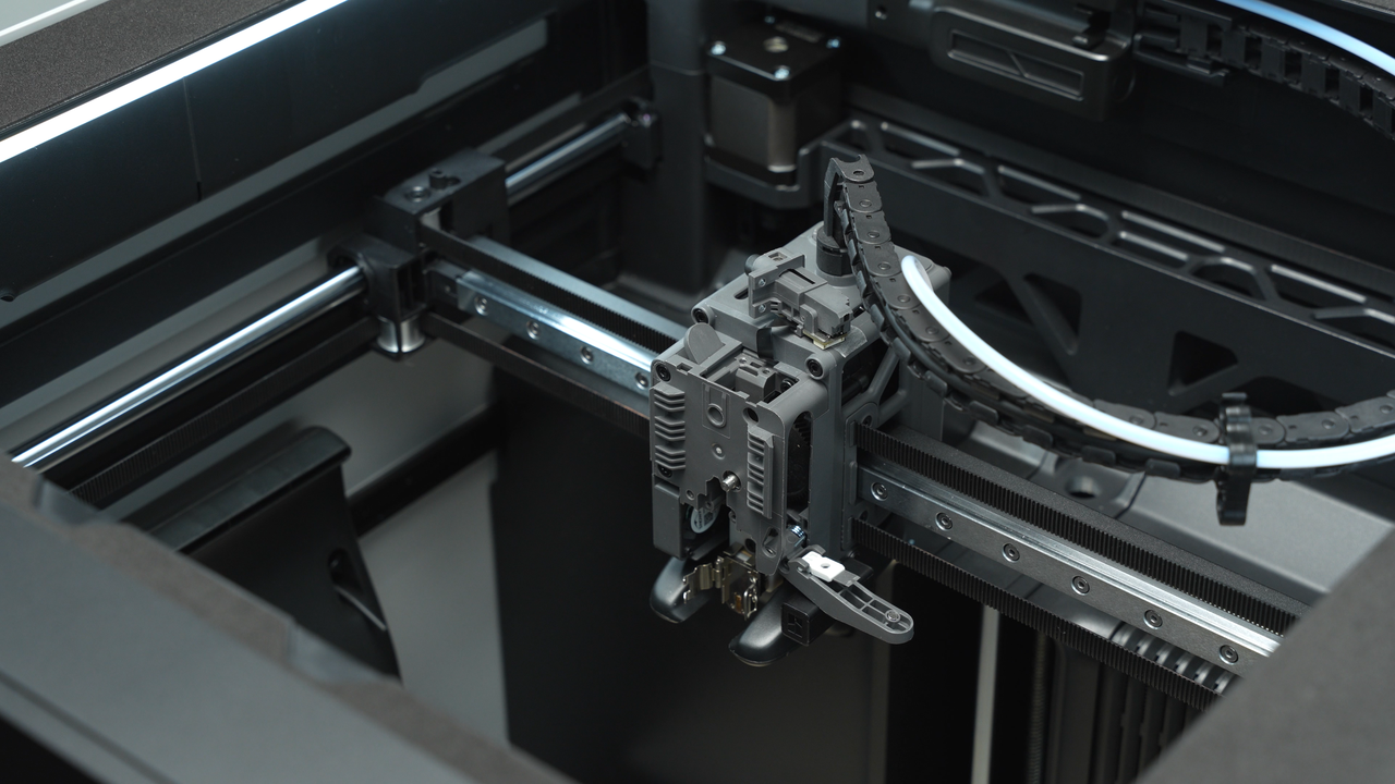
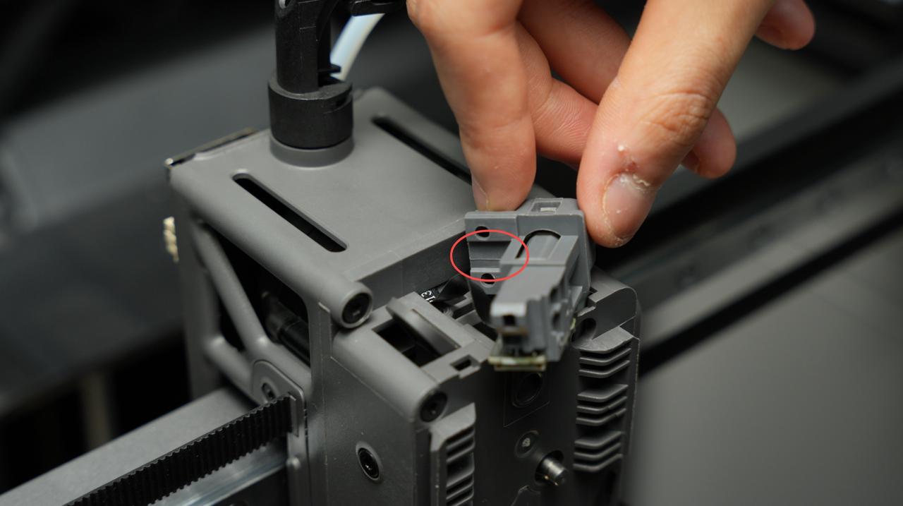
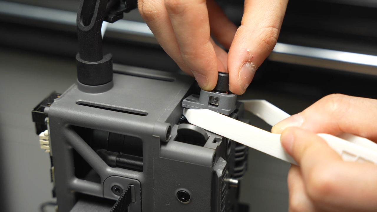
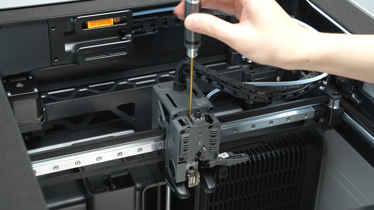
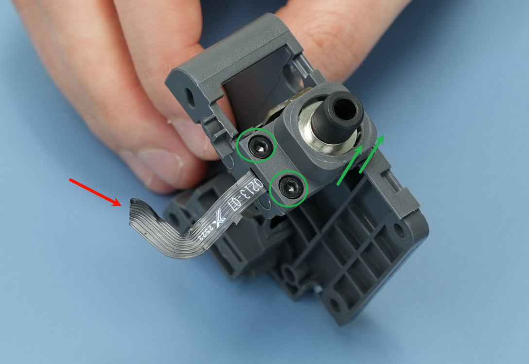
Use a H2.0 hex key to remove the 2 screws. Before removing the filament sensor, you can place double-sided tape above the tool head to hold the filament sensor in place to prevent it from falling off midway, as shown in the diagram. It is important to be careful not to damage the black FPC cable while positioning the filament sensor.
There is an FPC ribbon cable located at the back of the filament sensor. Please handle it with care during removal to avoid damaging or breaking the cable.
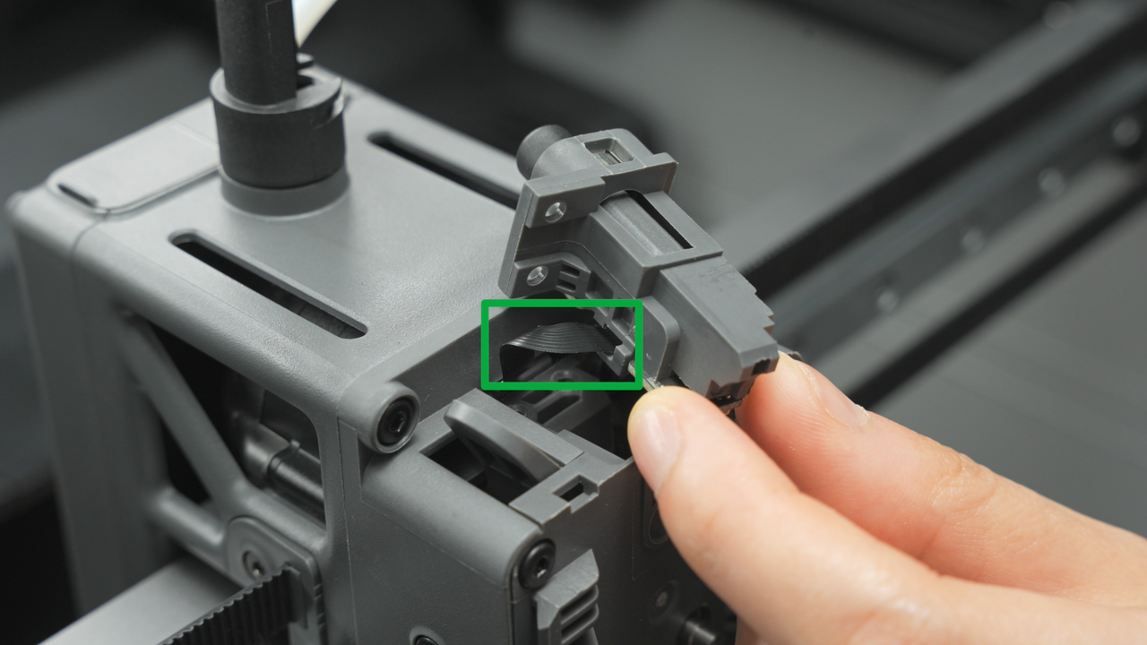
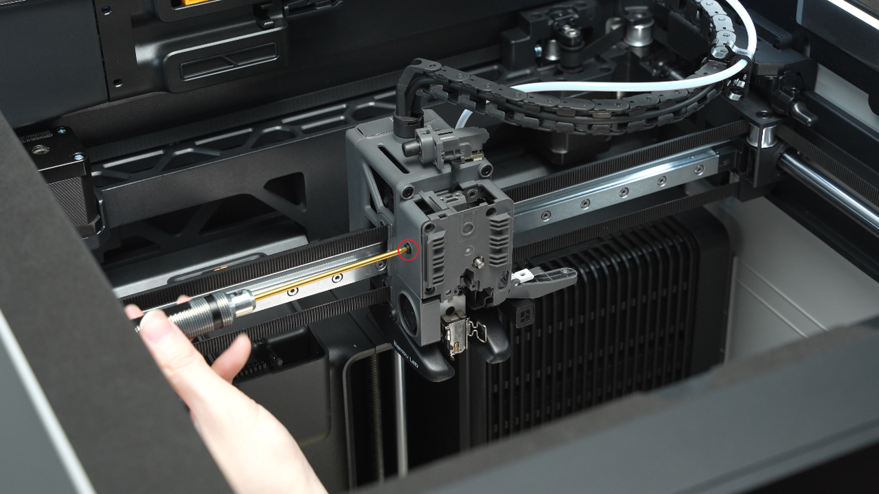
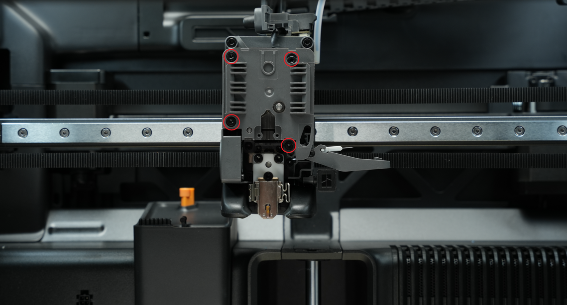
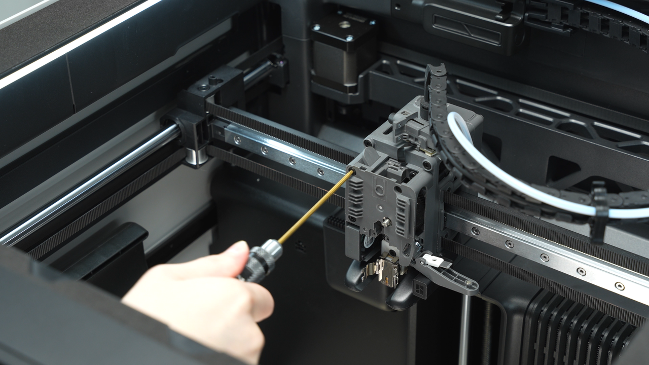
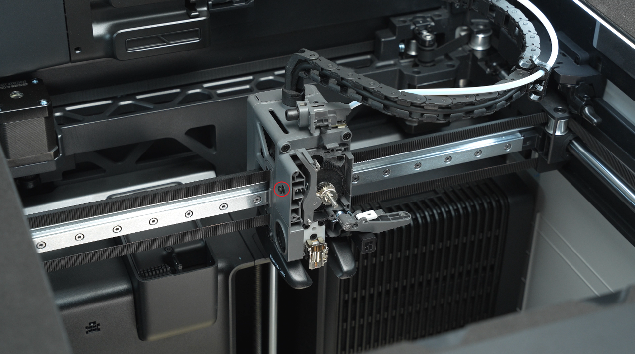
Before removing the extruder front cover, loosen the screw on the side first (just enough to loosen it slightly), and then remove the 4 screws on the extruder front cover.
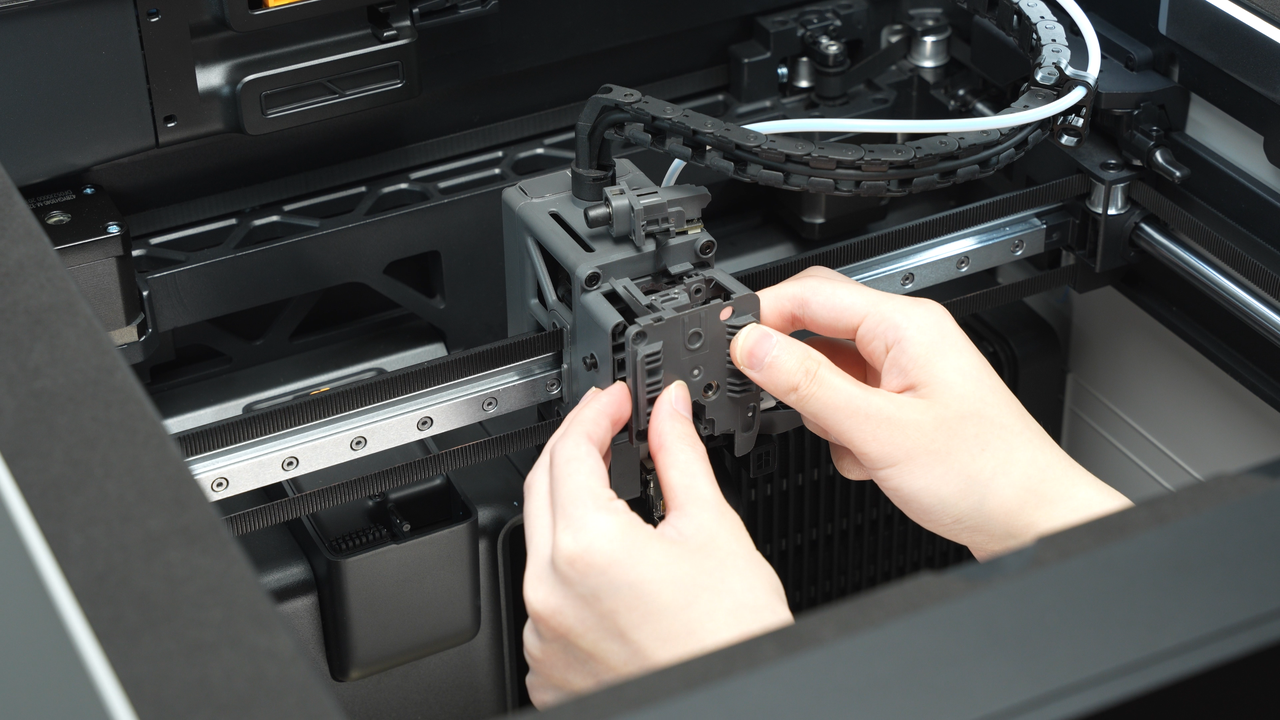
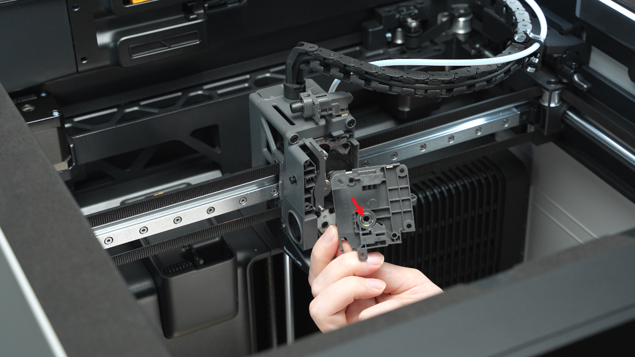
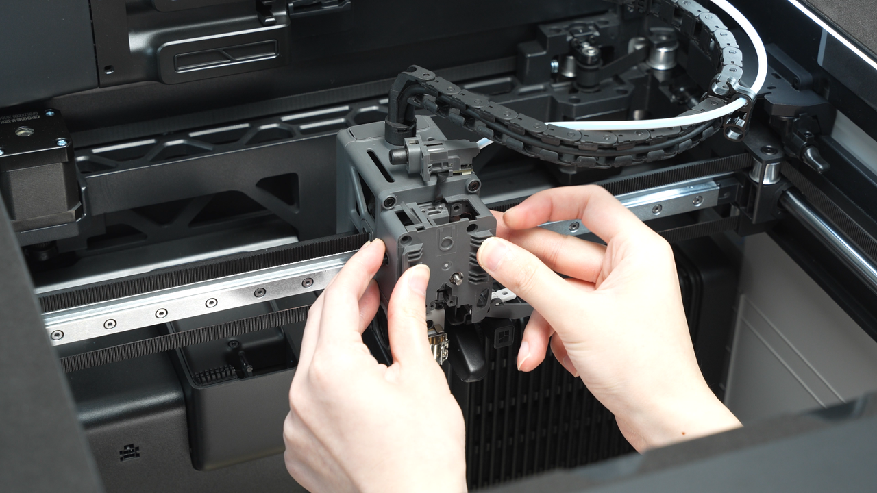
Carefully remove the extruder front cover with force. When removing the extruder front cover, be cautious of the front cover bearings and springs coming out.
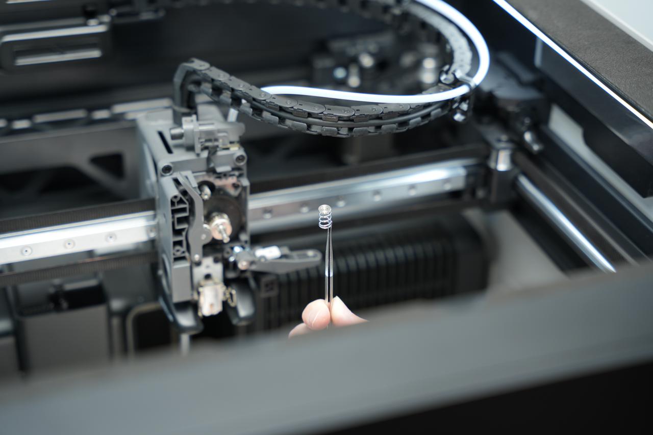
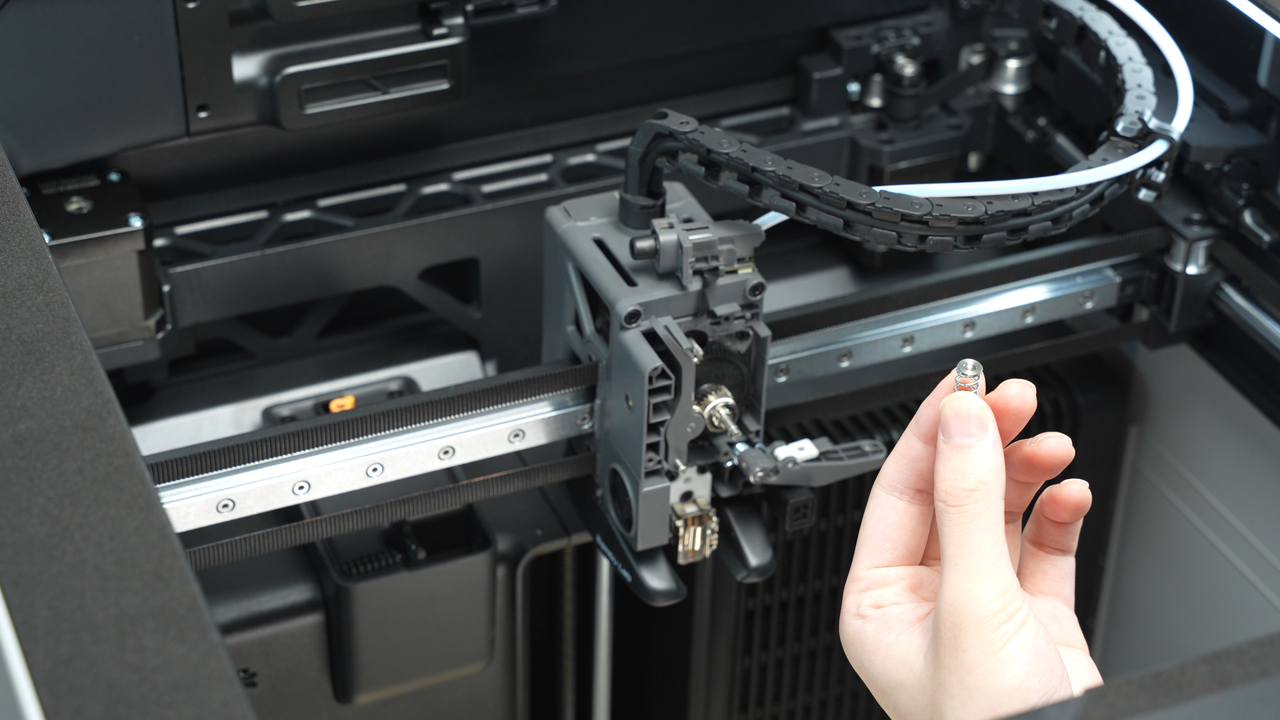
Completely remove the side screw, then carefully extract the internal spring and end cap with tweezer, and store them safely to prevent loss.
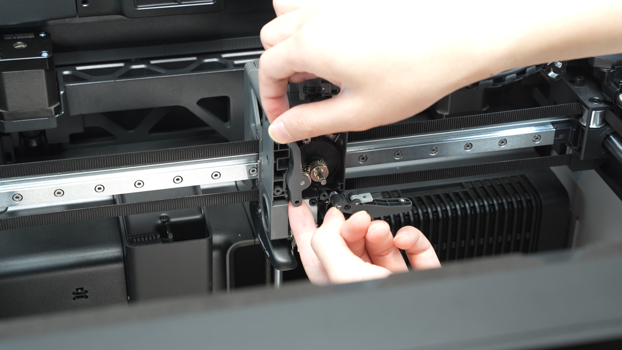
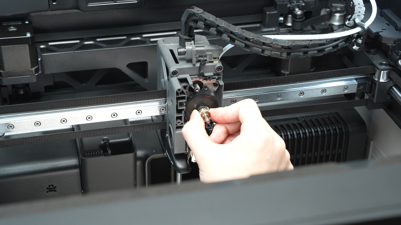
Remove the driven wheel bracket and take out the extruder gear.
Clean up the residual filament debris inside the extruder.
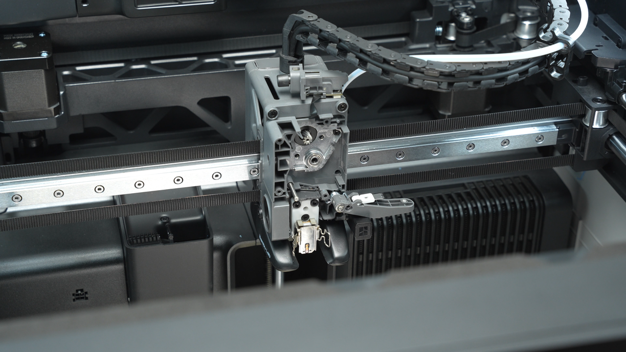
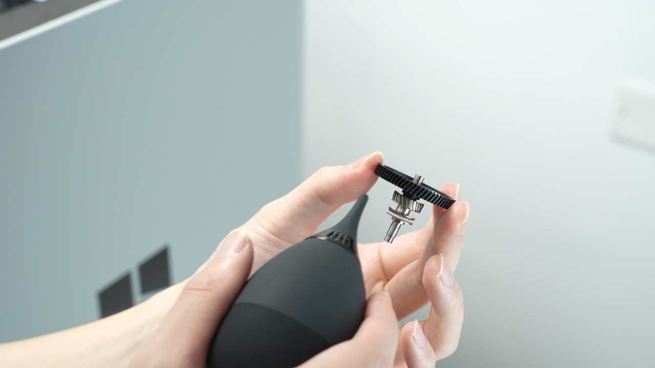
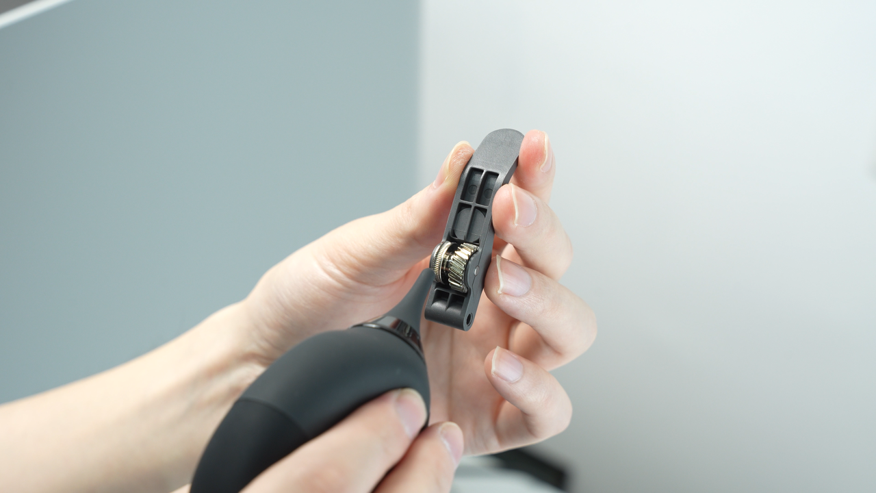
Also, use an air blower or tweezer to clean up the filament debris in the extruder gear and driven wheel.
¶ Step 5. Install the extruder and hot end
Install the extruder gear.
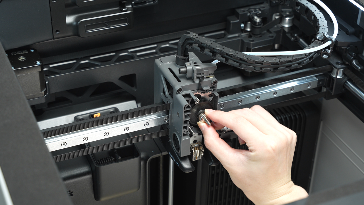
Install the driven wheel bracket to the corresponding shaft.
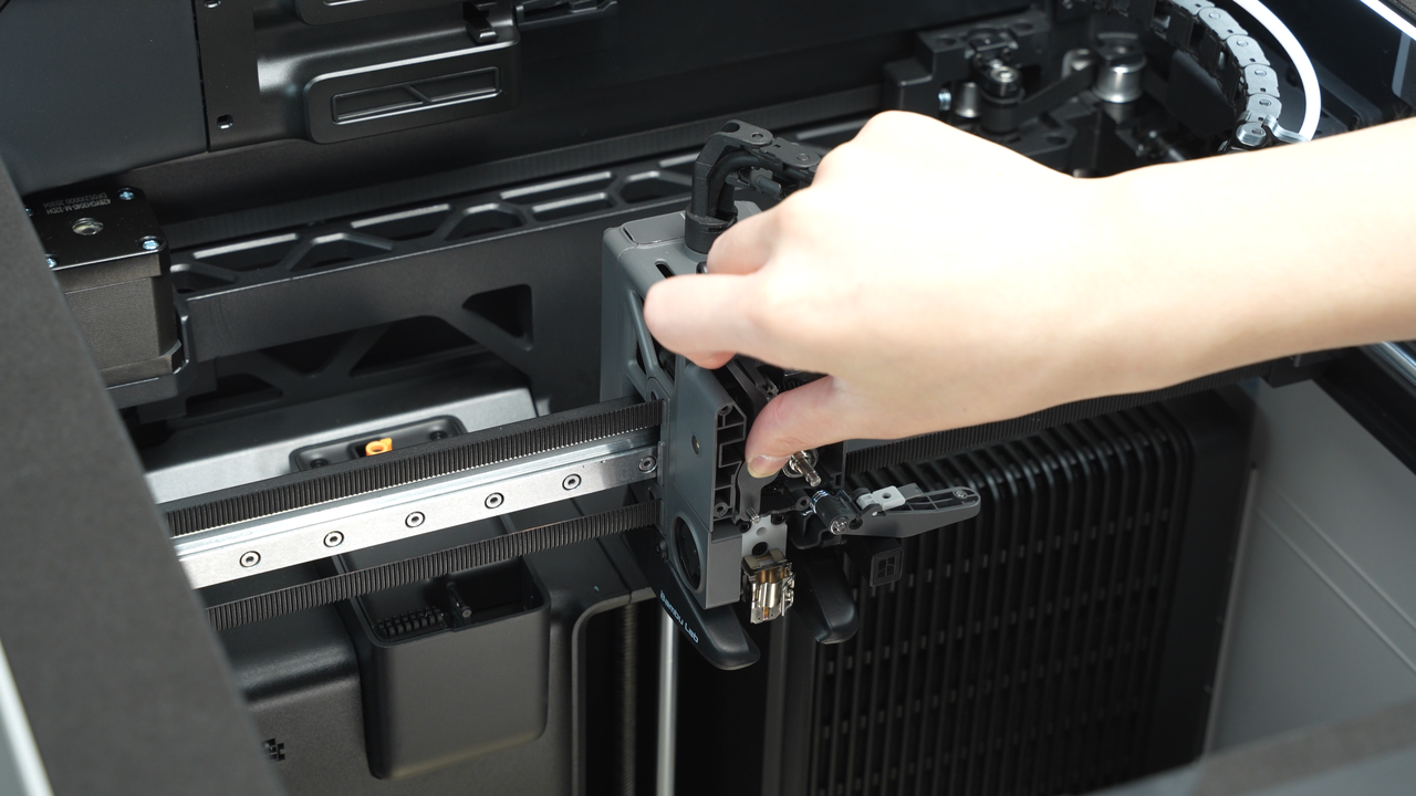
Next, assemble the spring and end cap in the correct orientation and position, ensuring that the end cap faces the side with the screw during installation. Using tweezer to place the spring and end cap into the corresponding position on the driven wheel bracket, then tighten the side screw to hold it in place, but do not fully tighten the screw yet.
Install the extruder front cover and screw in the 4 screws, then finally tighten the side screw of the extruder.
Remove the filament sensor from the tape. Before installation, ensure that the FPC cable is neatly organized within the cable management slot to prevent it from coming out, which could cause damage when inserting screws.
Ensure that the black FPC cable is not folded during the installation process. Then, secure the filament sensor in place by tightening the 2 screws.
Remove the tape from the tool head.
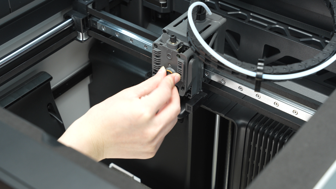
Lift the cutter handle with tweezer, slide the blade into place along the blade groove, tighten the screw to secure the cutter handle.
Install the hot end and lock the hot end latch, then install the silicone sock.
Install the filament guide block, tighten the 2 screws to secure the filament guide block in place.
Install the rotary wheel.
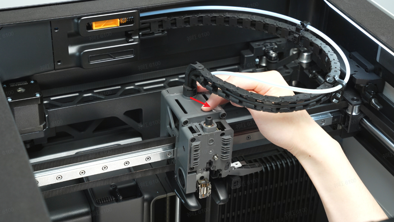
Install the PTFE tube and the tool head front cover.
After reinstalling the extruder and the hotend, resume printing or attempt manual extrusion to observe if the extrusion is functioning properly.
We hope the detailed guide provided has been helpful and informative.
If this guide does not solve your problem, please submit a technical ticket, we will answer your questions and provide assistance.
If you have any suggestions or feedback on this Wiki, please leave a message in the comment area. Thank you for your support and attention!


