¶ Controller Core
The core board is the heart of CyberBrick, offering logic control, wireless connectivity and programming capabilities. All current CyberBrick projects use the same core board, giving creators a unified development standard and enabling users to switch between different projects without buying multiple expensive main control boards.
Based on the ESP32-C3 microprocessor (MCU), the core board provides key GPIO pins and supports Bluetooth and WiFi connectivity. It comes with CyberBrick’s unique underlying runtime library and Bluetooth-upgradable firmware. Creators can develop with MicroPython at the application level. For programming details, refer to the Code Repository.
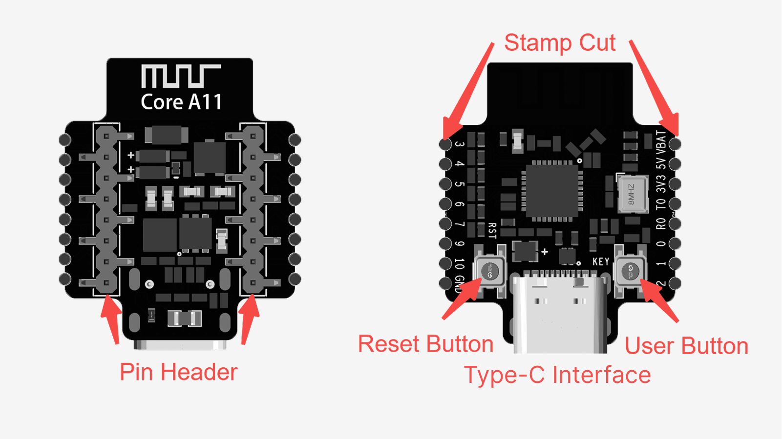
¶ Multi-Function Controller Core-XA003
Type-C interface input voltage: 5V
Battery input voltage: 3.7V–12.6V
Remote control range: 4m
- Pin header: Soldering pins. Allows users to solder wires for custom circuit connections.
- Reset button: Push-button switch. Press to reset the core board’s main control program.
- User button: Push-button switch. Programmable for custom user functions.
- Type-C interface: Type-C port. Connects to a PC via a data cable for programming and firmware upload.
- Pin headers: Connects to expansion boards.
¶ Indicator Light Status Guide for the Core Board:
- Power on (not connected): steady green.
- Bluetooth connected: steady blue.
- 2.4G master - slave connected: steady yellow.
- Bluetooth and 2.4G connected: blue and yellow alternate blinking.
- Transferring/updating settings: blinking green (2Hz) till done.
- ID light show: blinking green (1Hz), 5-second duration.
- Firmware update failed: steady red.
- Firmware update pending: steady white.
- Firmware updating: fast - blinking white.
¶ Pinout
If you need to design and connect circuits on your own, refer to the following figure:
¶ Functional Shields
The core board's computational power must be complemented with various peripheral devices to create interesting applications. In CyberBrick's first - batch projects, remote - controlled vehicles are the most common application, which often use output devices like motors, servos and LEDs on the vehicle, while the remote controller needs to read signals from input devices such as buttons and joysticks. Therefore, we've launched two functional shields for the transmitter and receiver ends. They convert the main control board's GPIO into peripheral device interfaces and incorporate additional circuits for driving motors.
CyberBrick also has advantages over traditional development boards, thanks to its standardized, solder-free connectors and standard libraries. Users can simply plug in the required modules as per the instructions and call the corresponding software controls. This eliminates the need to worry about interface and voltage compatibility or search for the necessary code libraries.
¶ Remote Control Transmitter Shield-XA005
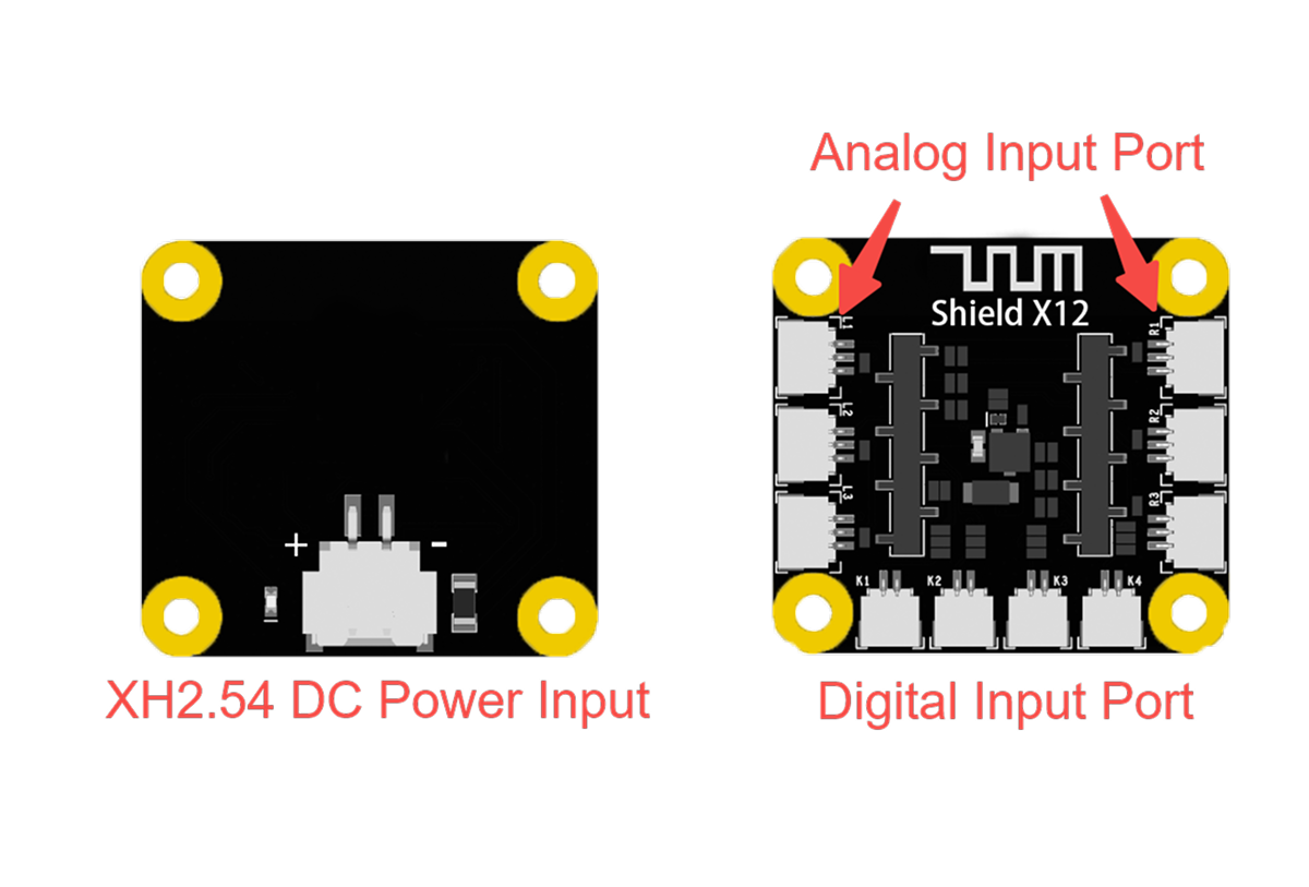
The remote controller's transmitter board has 3 analog input channels on each side (L1–L3, R1–R3) and 4 switch input channels below. Its rear gray slot is the core board slot. It's powered via an XH2.54 power port, with a white indicator light near the port illuminating when powered.
- Analog input channels (L1–L3, R1–R3): 3 - pin SH1.0 female headers. Connect to joysticks or toggle switches.
- Switch input channels (K1–K4): 2 - pin SH1.0 female headers. Connect to switches or buttons.
- XH2.54 power port: 2 pin XH2.54 female header. Connect to 4.5V–12.6V lithium or dry cell battery boxes.
Input voltage: 4.5V–12.6V.
Operating current: 65mA.
Channels: 6 x analog (SH1.0 3P), 4 x digital (SH1.0 2P).
¶ Remote Control Receiver Shield-XA004
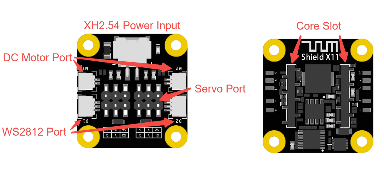
The remote controller's receiver board has one DC motor port and one LED port on each side, four servo ports in the center. It's powered via an XH2.54 power port, with a white indicator light near the battery port.
- DC motor ports M1, M2: 2 - pin SH1.0 female headers. For brushed DC motors, supporting rotation control and PWM speed regulation.
- LED ports D1, D2: 3 - pin SH1.0 female headers. For LED boards or WS2812 - protocol LED strips.
- Servo ports S1–S4: 3 - pin headers. For common 5V servos.
- Core board slot: Dual - row gray slot for connecting the core board.
- XH2.54 power port: 2 - pin SH1.0 female header. Connects to 7.4V–12.6V lithium or dry cell battery boxes.
Input voltage:7.4V-12.6V
Max operating current:3A
Channels: 2x DC motor ports (SH1.0 2P), 4x servo ports, 2x LED ports (SH1.0 3P).
¶ Input Module
Input modules, like joysticks, buttons, and touch sensors, capture user actions or environmental changes and convert them into system - recognizable signals. When you push a joystick or press a button, the system receives the corresponding control commands via these modules.
¶ Single-Axis Joystick Module-XA009
Single-channel joystick modules are single-axis analog input modules that auto-center when not in use. Unlike dual-channel joysticks, they move in one direction, outputting a single analog signal. They're ideal for controlling speed or position in independent motion systems.
For instance, in a vehicle model, one module can control speed while another handles steering. In a tower crane model, it can control hook height. On a tracked vehicle, two modules can separately control each track's speed.
¶ Hardware Connection
Connect the single - channel joystick module's terminal to an SH1.0 - 3pin cable, and link the cable's other end to the analog input ports on the remote transmitter board's sides.
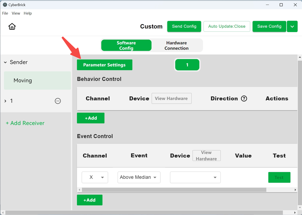
¶ Software Configuration
Behavior control allows devices to output corresponding to the analog values of designated channels. It's commonly used for controlling motor speed or servo angles via joysticks. You can view the hardware connection status of the receiver, including motor devices, by checking "Hardware Connection" beside the motor devices.

Event control divides each channel's values into three cases (greater than, equal to, or less than the median), allowing you to control a device's status. It can link actions, like connecting turn signals to steering movements.
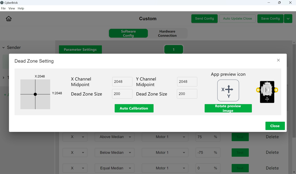
If the joystick drifts after centering, use parameter settings to perform mid-point calibration and adjust the dead zone size.

¶ Dual-Axis Joystick Module with 3Pin SH1.0 Connectors-XA011
A dual-channel joystick module is a two - axis analog input device that automatically centers when not in use. It's suitable for controlling both speed and direction in scenarios where movements are interrelated. For instance, in vehicle models, one axis can control movement speed while the other steers. In crane models, one axis can handle rotation and the other controls distance.
¶ Hardware Connection
Connect each end of the dual - channel joystick module to an SH1.0-3pin cable, and plug the other ends of these cables into the analog input ports on the sides of the remote transmitter board.
¶ Software Configuration
Behavior control adjusts a device's output to match the analog values of a designated channel. It's often used for joystick-based motor speed or servo angle control. Checking "Hardware Connection" beside motor devices lets you see the receiver's hardware connection status.
Event control splits each channel's values into three cases (greater, equal, or less than the median) to control device status. It can bind actions, like linking turn signals to steering movements.
If the joystick drifts after centering, use parameter settings to perform mid-point calibration and adjust the dead zone size.

¶ Three-Position Rocker Switch Module-XA010
A 3 - position switch module is a single - channel analog input module with three switch positions representing three states.
It can be fixed in left, center, or right positions, making it ideal for state-switching tasks like toggling lights or transformations. For example, it can switch vehicle model headlights on/off or control multiple vehicles in a one-to-many remote control setup.
¶ Hardware Connection
Connect the 3-position switch module's terminal to an SH1.0-3pin cable, and plug the cable's other end into the analog input ports on the remote transmitter board's sides.
¶ Software Configuration
In the three - position switch module configuration interface, you can set the device status corresponding to the switch status, such light as effects, motor speed, and servo position. Suitable for switching light states and controlling model transformations.
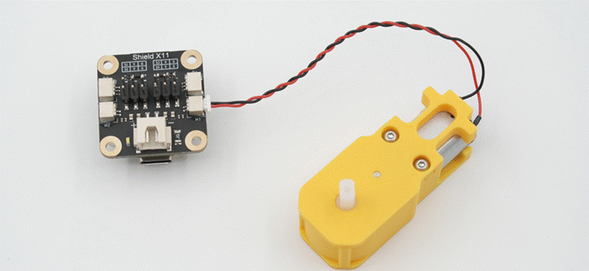
¶ Power Switch Module-XA007
The switch board is a dual-position switch. It's used to control power on/off without removing the battery. It has two 2-pin XH2.54 ports and is usually connected in series between a power source (like a lithium battery) and functional shields (like remote transmitter/receiver boards). This allows you to cut off power without removing the battery, preventing battery drain from standby mode.
¶ Hardware Connection
Connect one side of the switch board to the power source, and the other side to an XH2.54 2 - pin cable. Connect the other end of the cable to the XH2.54 power port on the expansion board.
¶ Momentary Button Module-XA008
The momentary button module is a binary input module that can recognize various actions, including short press, long press, button down and button up.
Unlike a three-position switch, it has only two states: pressed and released, and it always returns to the released state. This module allows for cycling through modes in a set order, and triggering or stopping actions in real-time. For example, it can trigger a launch mechanism in a model or switch light modes and colors in models with LED lights.
¶ Hardware Connection
Connect the momentary button module's terminal to an SH1.0 2 - pin cable, and plug the cable's other end into the digital input port on the underside of the remote transmitter board.

¶ Software Configuration
In the button module configuration interface, you can switch the status value of corresponding components via short press, long press, press and release actions.
Click the value to add multiple status values, allowing sequential switching between them.
¶ Output Module
Output modules perform actions based on input signals, showcasing the model's responsiveness. Examples include motors, servos, and LED lights. When the system detects signals from input modules, output modules react by moving, lighting up, etc., completing the interactive process.
¶ WS2812 LED Hub-XA006
An LED bead adapter connects WS2812 - protocol LED beads to the LED port on the expansion board, enabling independent control of multiple RGBW LED beads. It's ideal for models requiring numerous LEDs.
¶ Hardware Connection
Connect the horizontal 3 - pin SH1.0 port to a 3 - pin SH1.0 cable, and plug the cable's other end into the LED port on the remote receiver board's side. Connect the WS2812 LED strip's cable to the four vertical ports.
¶ Software Configuration
In the settings, click 1, 2, 3, or 4 below the activated LED to select the controlled LED bead. Choose a solid or blinking mode, pick a color, and set the blink frequency with repeat and time settings.
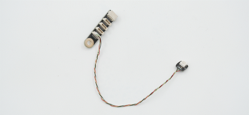
¶ WS2812 RGB LED-KB003
The WS2812 RGB LED, an RGBW bead with a wire and WS2812 protocol support, can emit multi-colored light. When used with an LED adapter, multiple beads create various visual effects, making them ideal for models requiring lighting, like vehicle headlights.
¶ Hardware Connection
Plug the connector of the WS2812 LED bead into the vertical terminal of the LED adapter.
¶ Software Configuration
Use it with an LED bead adapter. For details, see the software configuration section above.
¶ 030 Micro DC Motor-LA024
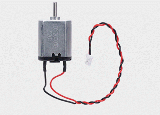
The 030 brushed motor, a compact motor balancing size and power, can be paired with gearboxes of varying reduction ratios to form single- or dual-shaft gear motors with different speeds. It suits models needing sustained motion but not precise speed control, like chassis motors in vehicle models or rotary table drive motors.
¶ Hardware Connection
Connect the 030 brushed motor connector to the DC motor ports on the remote receiver board's sides.
¶ Software Configuration
In the motor settings interface, you can adjust the maximum speed for forward and reverse rotation, as well as the bias. The bias determines the motor's default speed when the joystick is centered.
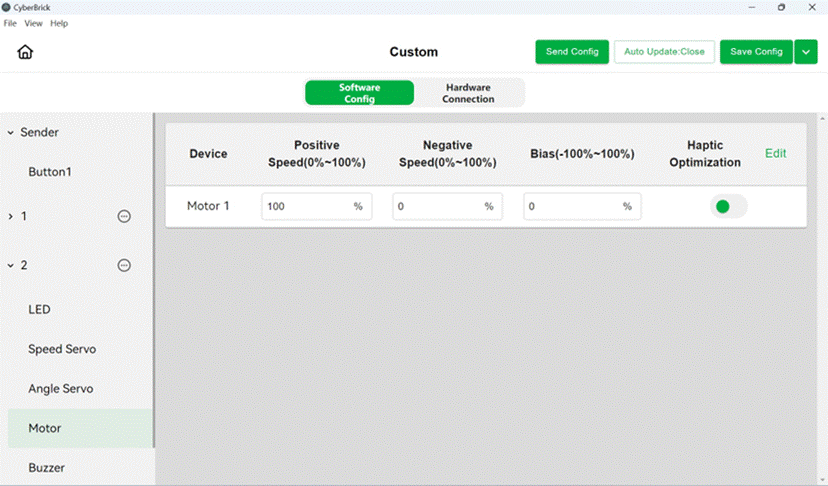
Haptic Optimization enables a non-linear relationship between joystick values and motor speed, allowing for precise low-speed control and fast high-speed response. You can customize the game feel optimization in the settings.
¶ N20 Reduction Gear Motor
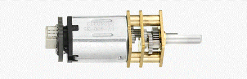
There are 3 variants of N20 Reduction Gear Motor:
- 150RPM - LA002
- 400RPM - LA003
- 1000RPM - LA004
The N20 brushed DC motor, smaller than the 030 version, offers various shaft and speed options. It suits small - sized models needing continuous motion, low torque, or joint self - locking (use side - shaft N20 motors). Examples include vehicle chassis motors and joint drive motors for robotic arms and rotary tables.
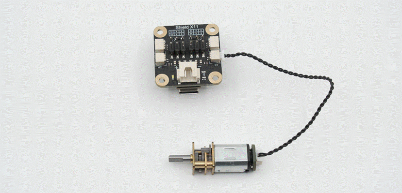
¶ Hardware Connection
Connect one end of a 2-pin SH1.0 cable to the N20 brushed motor terminal and the other end to the DC motor ports on the remote receiver board's sides.
¶ Software Configuration
All DC brushed motor configurations are the same. For details, see the software configuration section for the 030 motor above.
¶ 9g Servo Motor 360°-PG002
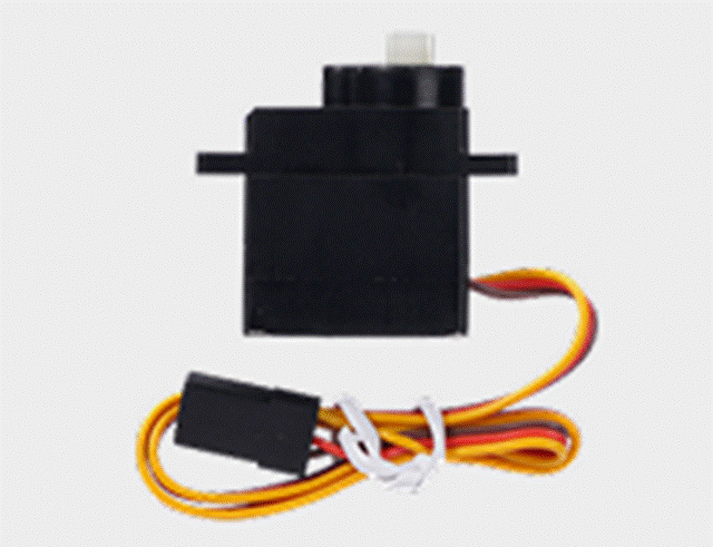
A speed servo is a motor with a speed closed-loop. Compared to other brushed motors, the 9g speed servo has low torque but can maintain a constant speed and operates quietly. It's often used to drive small, lightweight decorative parts in models.
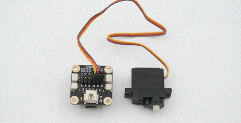
¶ Hardware Connection
Plug the 9g speed servo's connector into the servo port on the remote receiver board.
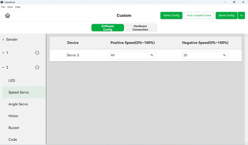
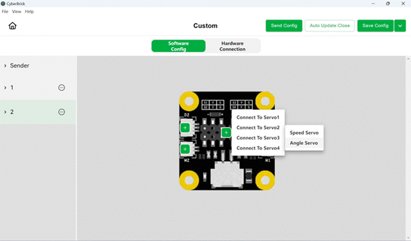
¶ Software Configuration
Adjust the speed servo's maximum and minimum speed in the settings interface.
¶ 9g Servo Motor 180°-PG001

An 180° servo is a position closed loop motor. The 9g 180° servo, similar in appearance to a speed servo but differing in function, maintains a set angle rather than speed. This makes it ideal for steering and transformation mechanisms, such as controlling the steering rack in vehicle models or joint angles in robotic arm models.
¶ Hardware Connection
Plug the 9g speed servo's connector into the servo port on the remote receiver board.
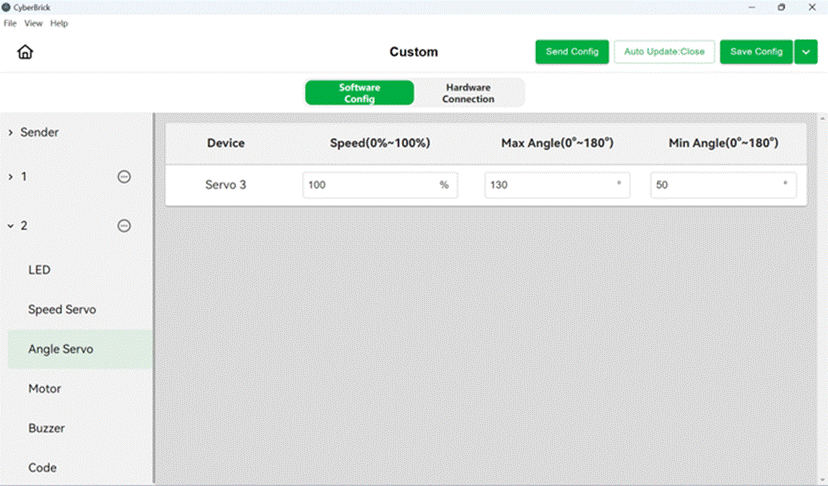
¶ Software Configuration
Click the "+" next to the servo port in the configuration interface to add an angle servo.
Adjust the rotation speed and max/min angles of the angular servo in the settings interface.