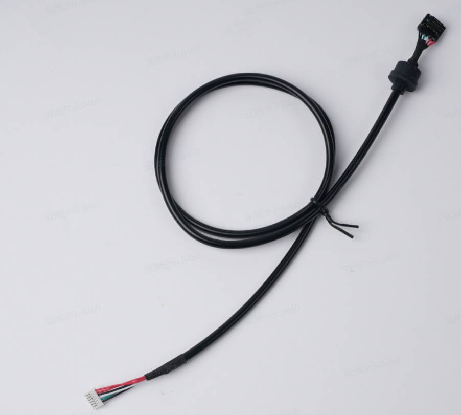
¶ Toolhead cable
It is the signal cable from the MC board to the extruder board on the toolhead.
¶ Tools
H1.5/H2.0 hex key
¶ Preparation
Disconnect the power cord cable
¶ Disassembly
¶ Step 1 - Remove the rear panel
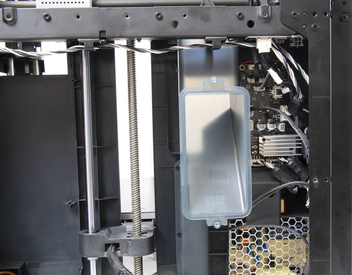
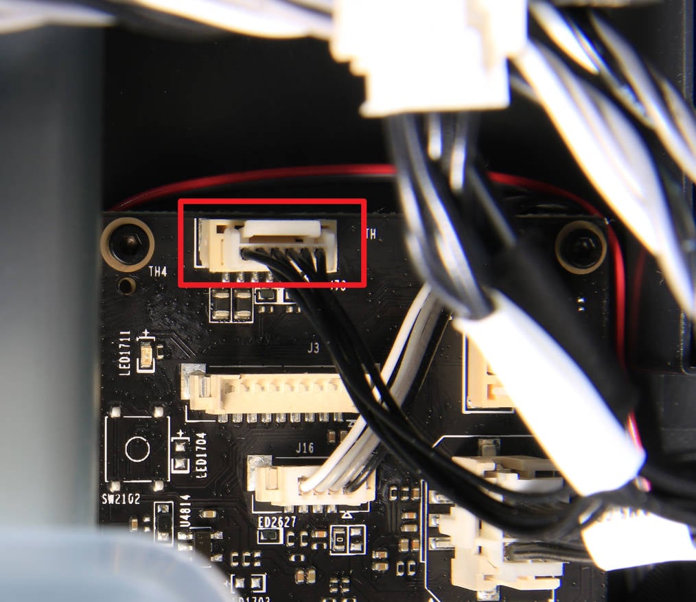
Remove the Rear panel/Rear metal panel, and then disconnect the toolhead cable from the MC board.
 |
 |
¶ Step 2 - Remove the rear housing of the toolhead
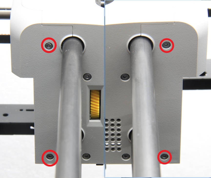
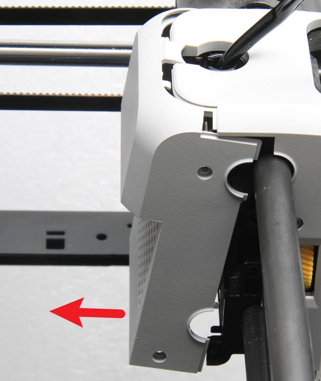
Unscrew the 4 screws that fix the rear housing of the toolhead and remove the rear housing.
 |
 |
¶ Step 3 - Remove the extruder board
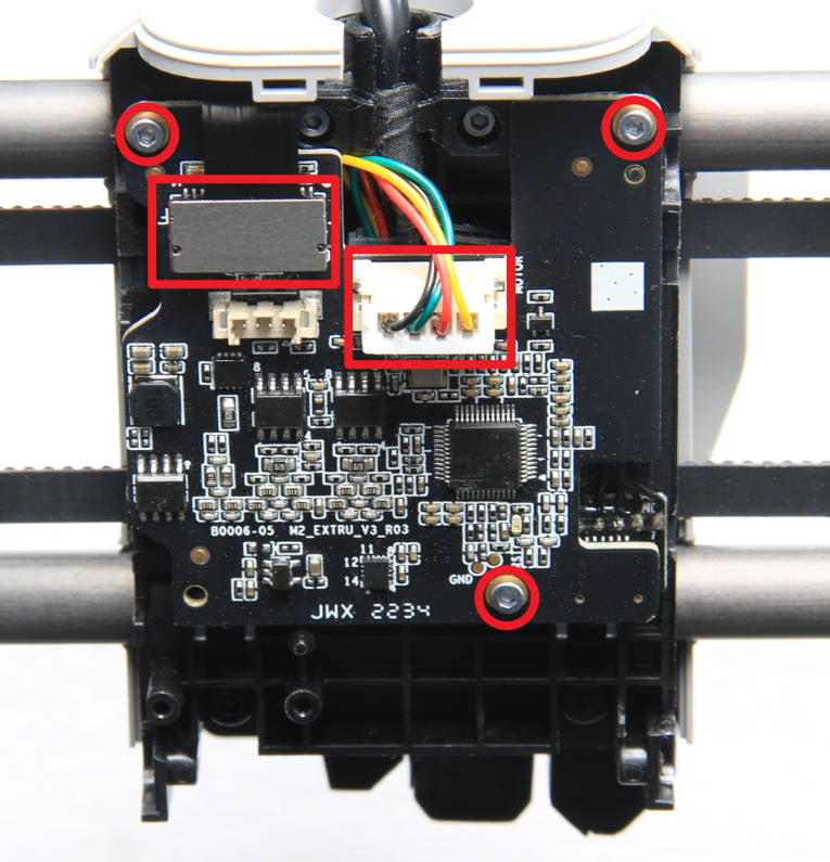
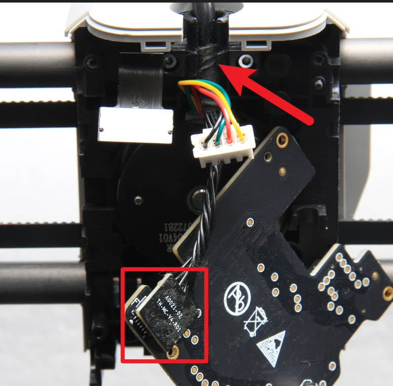
Disconnect the extruder FPC cable and the motor cable, unscrew the 3 screws with the H1.5 hex hey, and loosen the extruder board. Then flip the extruder board over, disconnect the cable at the bottom of the extruder board, and remove the extruder board.
 |
 |
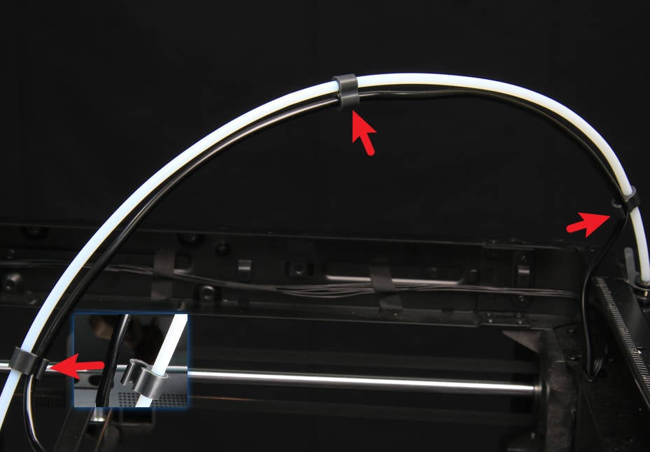
¶ Step 4 - Loosen the toolhead cable from the clips
Unhook the toolhead cable from the 3 cable clips.
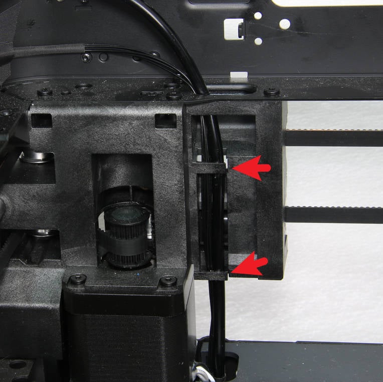
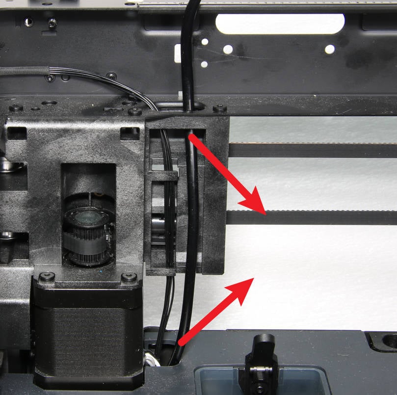
¶ Step 5 - Remove the toolhead cable
Loosen the toolhead cable from the cable slot and pull out the cable.
 |
 |
¶ Assembly
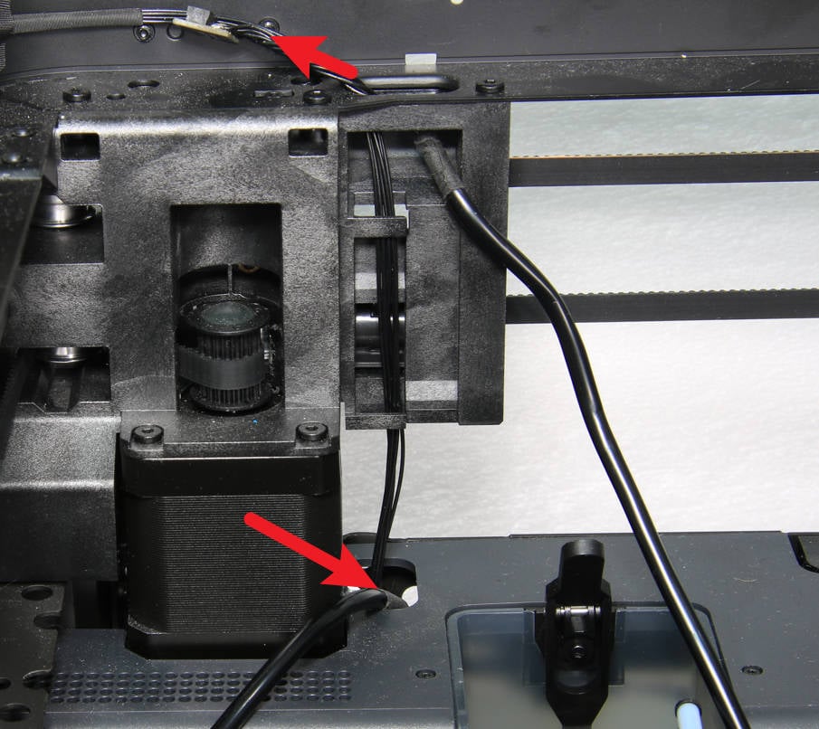
¶ Step 1 - Pass through the cable
Pass the two ends of the cable through the cable hole respectively, and stuff the cable into the cable slot.
 |
 |
¶ Step 2 - Connect the toolhead cable
Connect the cable to the connector on the MC board first, and then connect it to the extruded board.
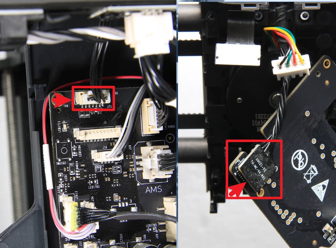
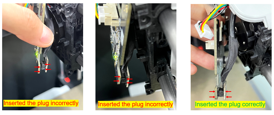
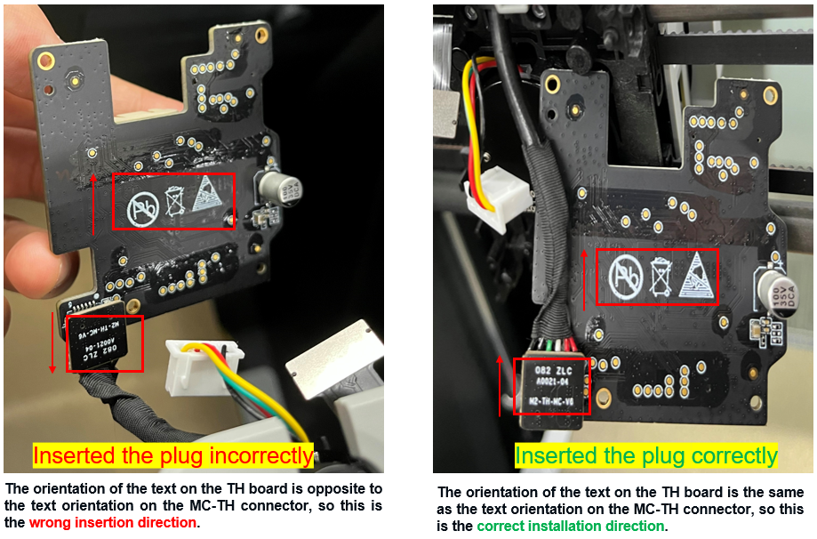
The MC-TH connector is directional, so please ensure the socket is inserted correctly. If it is inserted in reverse, it will cause a power short circuit, resulting in the printer reporting an HMS error or not being able to power on properly.
¶ Step 3 - Install the extruder board
Turn the extruder board over, with the motor connector facing outward, install it on the tool head, lock in 3 screws to fix it, and connect the extruder FPC and the motor cable.

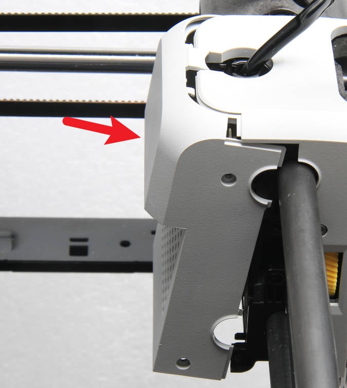
¶ Step 4 - Install the rear housing of the toolhead
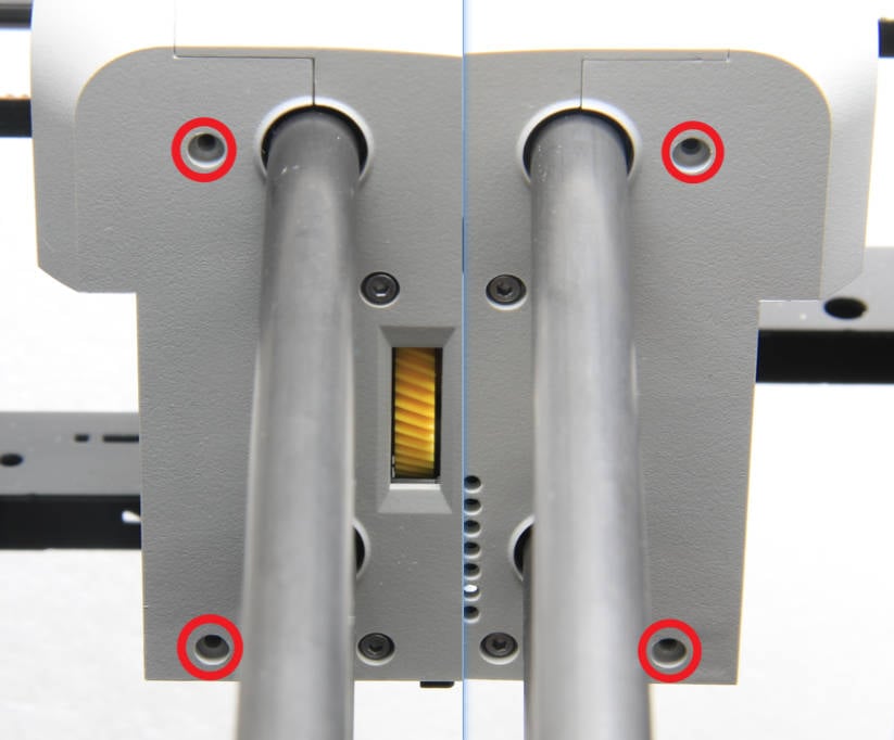
Install the rear housing of the toolhead and lock in 4 screws.
 |
 |
¶ Step 5 - Install the rear panel
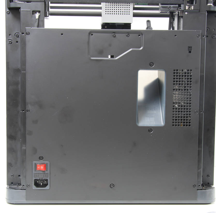
Refer to the contents of the Rear panel to install the rear panel.
¶ How to verify
1. Visually check the appearance, the joint positions are free of misalignment and floating;
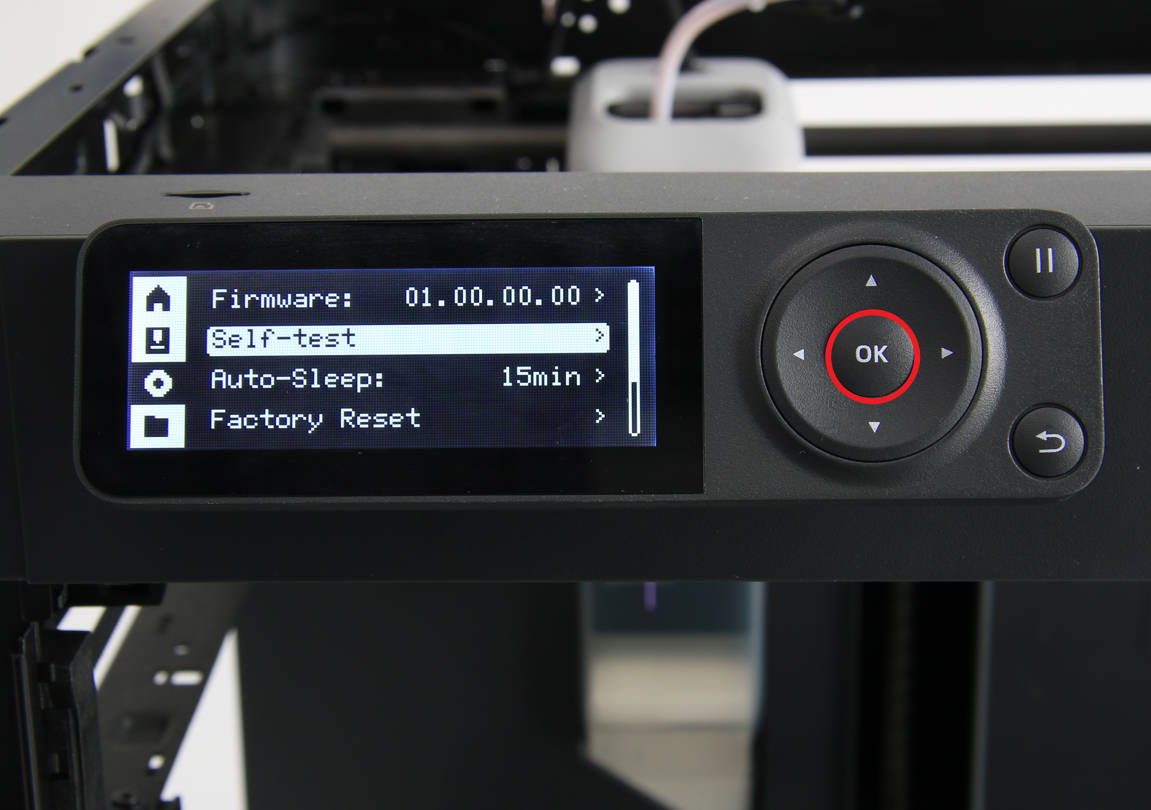
2. Power on the printer and run the device self-test process. If the self-test passes, the operation is successful.
