¶ P1P Enclosure Kit
We have introduced the new P1S 3D printer and simultaneously launched the official upgrade kit, enabling everyone to enjoy the majority of upgrades introduced by the P1S. To simplify the upgrade process, we have summarized installation guidelines for the relevant accessories included in the upgrade kit in this article.
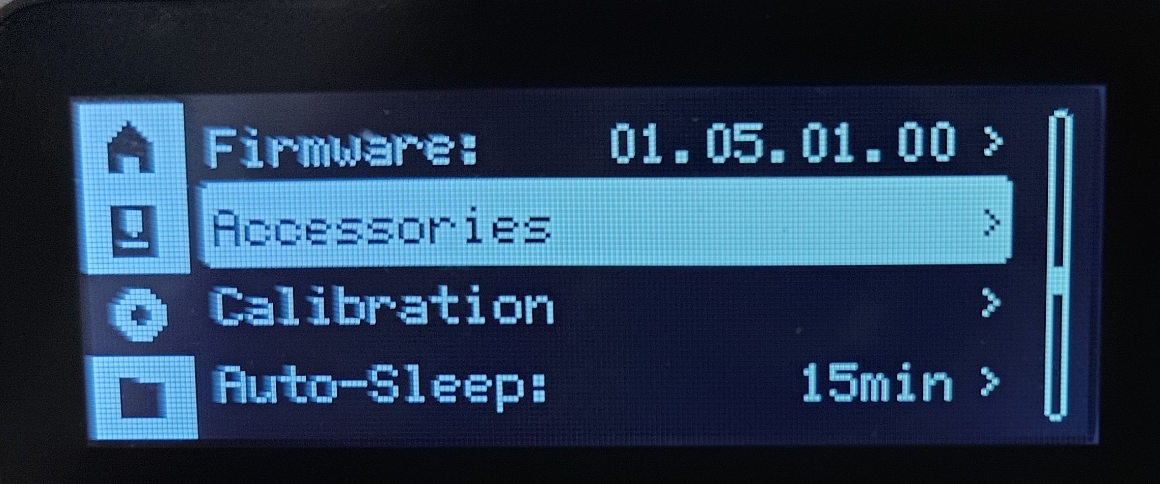
Note: Starting from P1 series OTA version 01.05.00.00 (Know more about it from P1P/P1S and AMS Firmware Release History), P1P now has support for the flag confirming if the P1P has been upgraded with an enclosure. It is available under "Accessories" -> "Upgrade Kit". When this option is selected, you can use the P1S Bambu Studio profiles without the prompt "Incorrect printer model". (Studio supported version: 1.8.1 and above).
After the P1P Enclosure Kit has been successfully installed, please do the following settings on the P1P:
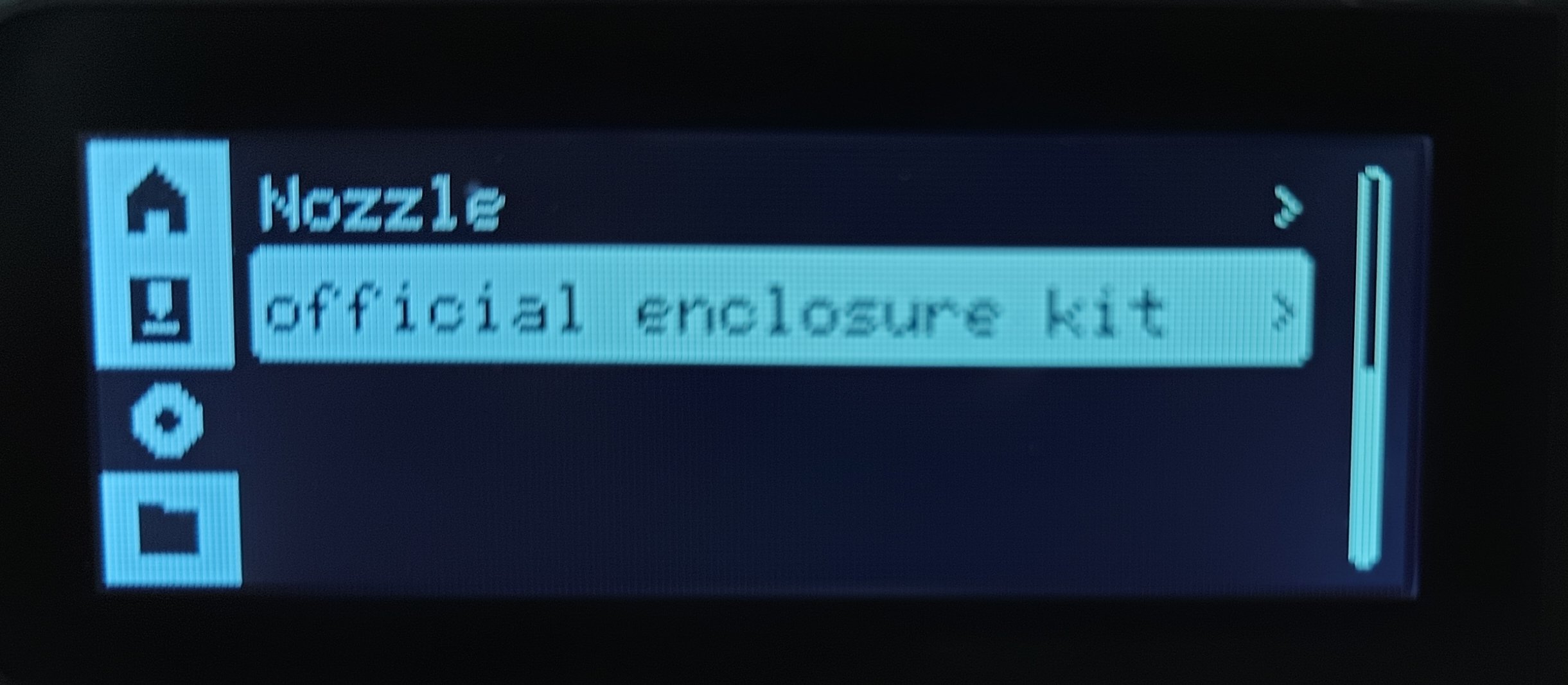
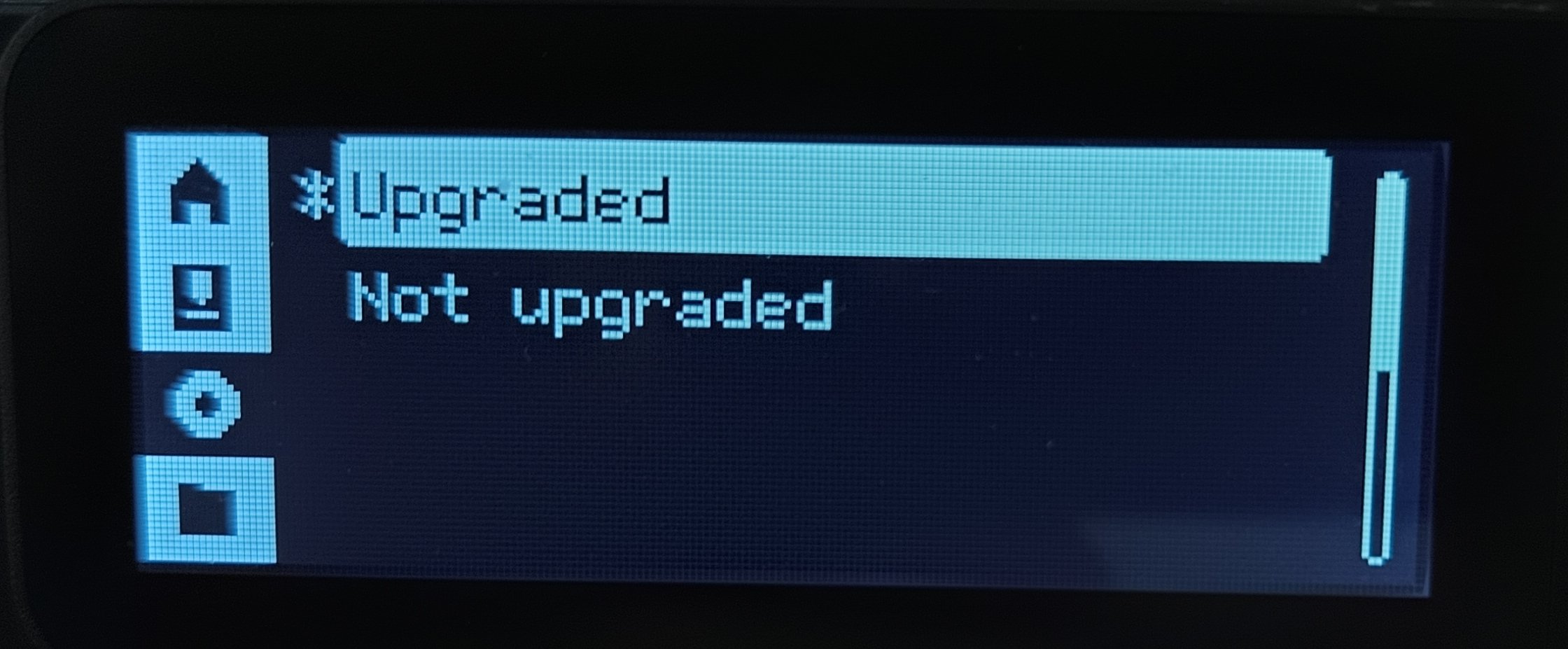
Click "Accessories" → "official enclosure kit" → "Upgraded".
You can also refer to this Firmware upgrade to update the P1P's firmware to the latest version.
¶ In the Box
(No.1~NO.7 are enclosing parts; No.8~NO.14 are upgrade parts)
| NO. | Commodities | NO. | Commodities | NO. | Commodities | NO. | Commodities |
| 1 | Glass Cover Plate | 5 | P1S Right Plastic Panel | 8 | PTFE Tube | 12 | Cable Chain Assembly |
| 2 | Front Glass Door | 6 | P1S Rear Metal Panel | 9 | Auxiliary Part Cooling Fan | 13 | P1P Heavy Duty Toolhead Cable |
| 3 | Front Door Mounting Kit | 7 | P1S Front Cover | 10 | Control Board Fan | ||
| 4 | P1S Left Plastic Panel | 11 | Chamber Temperature Regulator Fan |
Note: Before initiating the upgrade, it is recommended to 3D print the air duct for the chamber temperature regulator fan.
¶ Safety Warning
IMPORTANT!
It's crucial to power off the printer before conducting any maintenance work, including work on the printer's electronics and tool head wires. Performing tasks with the printer on can result in a short circuit, leading to electronic damage and safety hazards.
During maintenance or troubleshooting, you may need to disassemble parts, including the hotend. This exposes wires and electrical components that could short circuit if they contact each other, other metal, or electronic components while the printer is still on. This can result in damage to the printer's electronics and additional issues.
Therefore, it's crucial to turn off the printer and disconnect it from the power source before conducting any maintenance. This prevents short circuits or damage to the printer's electronics, ensuring safe and effective maintenance. For any concerns or questions about following this guide, open a new ticket in our Support Page and we will do our best to respond promptly and provide the assistance you need.
¶ Install the upgrade kit
Important
1. Please print the air duct (.3mf model) before upgrading, and we recommend installing the cable chain first(Installation Guide).
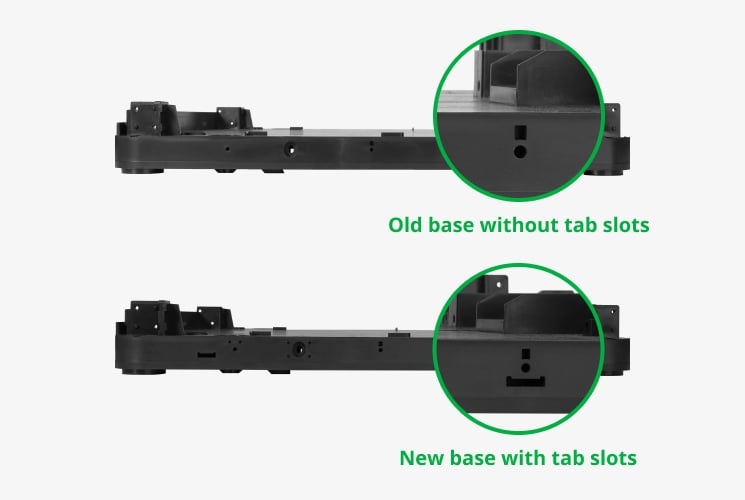
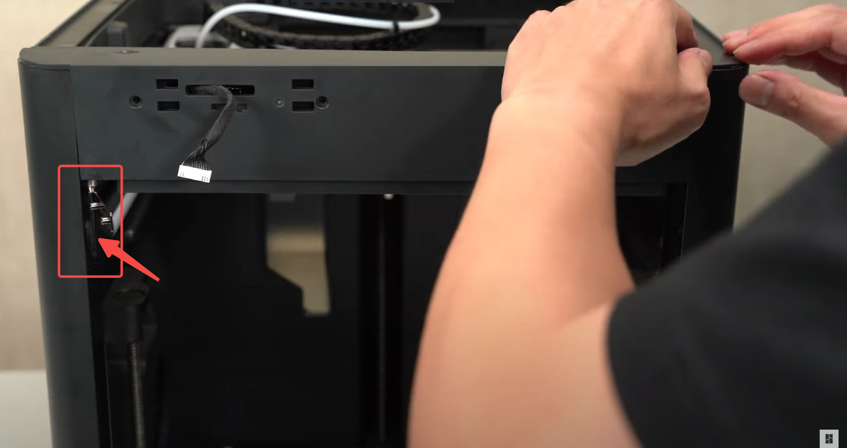
2. Due to the structural upgrades in the P1S, please follow the instructions below to inspect the side panels and printer base before installing the side panels. Remove the tabs if necessary.
 |
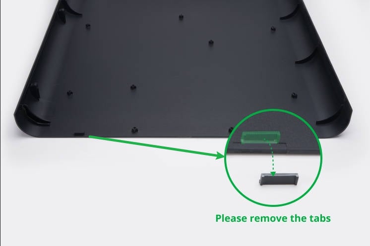 |
¶ Video Guide:
¶ Operation Steps:
1. Print the air duct (Click to download the .3mf model of the air duct)
2. Install the cable chain assembly and PTFE tube by following the installation guide(click here)
3. Remove the SD card, the screen, and then remove the front cover of the P1P
4. Install the front door mounting kit (1 screw is enough for the bottom hinge, if you want to lock 2 screws, you need to bend the interfering column slightly)
5. Remove the spool holder and the metal rear panel of the P1P
6. Remove the auxiliary part cooling fan bracket (if previously installed)
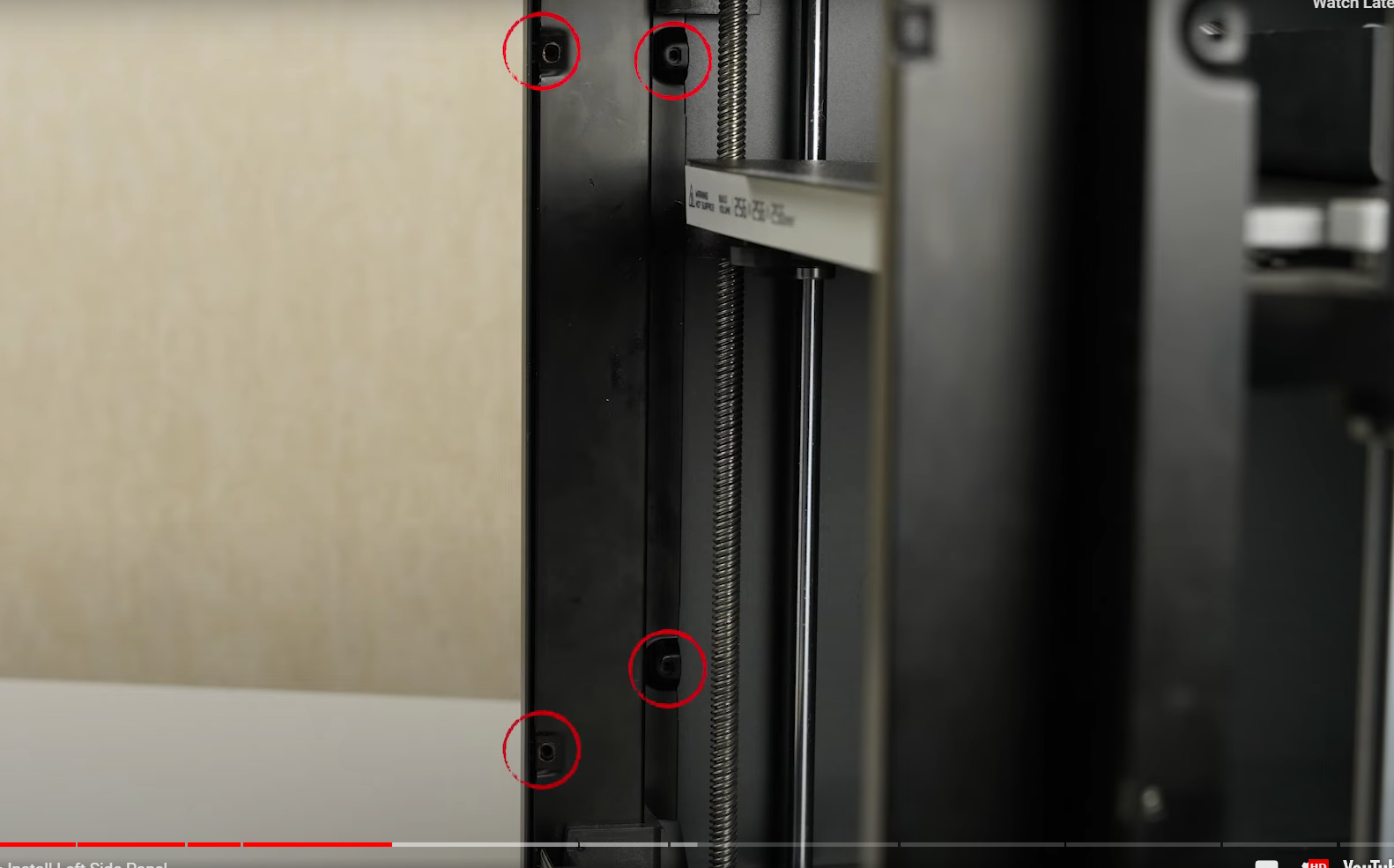
7. Install the left panel
8. Install auxiliary part cooling fan
9. Remove the heat sink of the MC board and install the MC board fan
Note: When installing the original heat sink of the P1P MC board, make sure the direction of the heat sink is correct. Installing the heat sink in reverse may result in direct contact between the heat sink and the 24V power supply, leading to a short circuit.
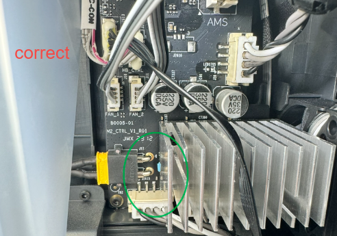 |
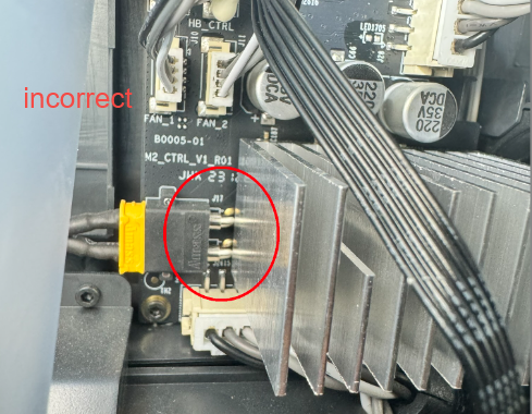 |
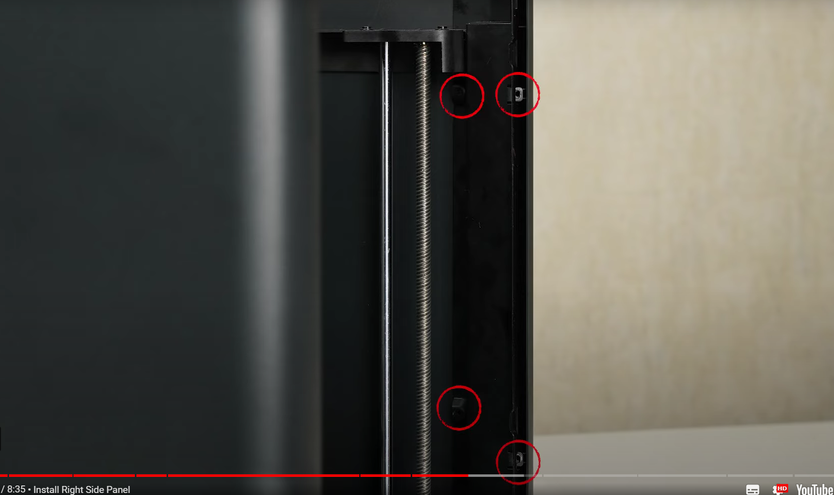
10. Install the right panel
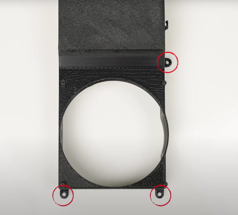
11. Install the chamber temperature regulator fan and place the activated carbon air filter
When installing the fan, screws are not required. Simply attach the fan to the air duct. As shown in the video, three screws are needed to secure the connection between the air duct and the printer's lining.
12. Install the P1S metal rear plane and install the spool holder (Please ensure the cable chain installation is completed before installing the rear panel)
13. Install the P1S front cover, the screen, and the micro SD card
When installing the front cover, rotate the hinge outward to prevent it from getting stuck inside the front cover.
If you encounter difficulty in fitting the front cover during installation, you can try loosening the screws located in front of the left and right side panels slightly (as shown in the diagram below). This will make it easier for the front cover to fit in.
 |
 |
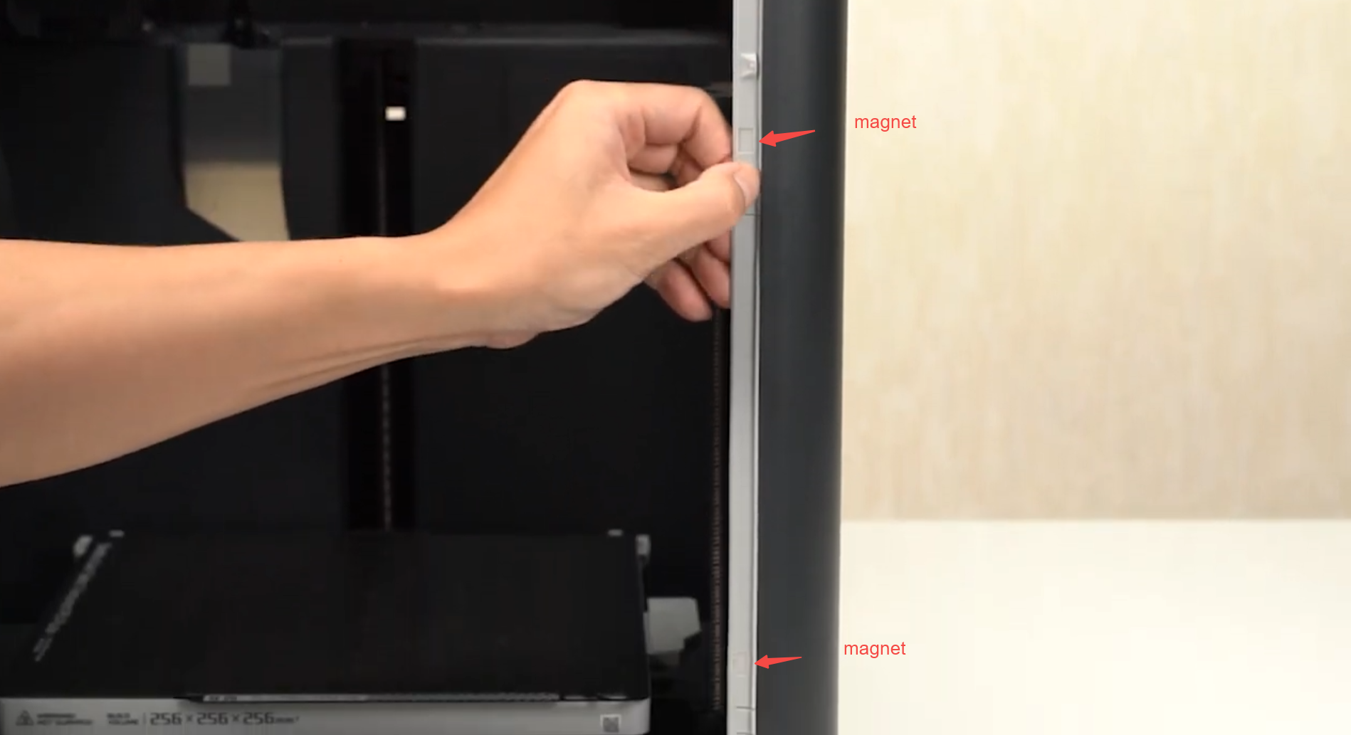
14. Install the front door rubber strip, install the glass front door, and place the glass upper plate
The front door seal is elastic and may undergo deformation during installation. We recommend aligning the front door seal based on the position of the magnet.
¶ Screws list
| Model | Position | Drawing | Model | Position | Drawing | ||
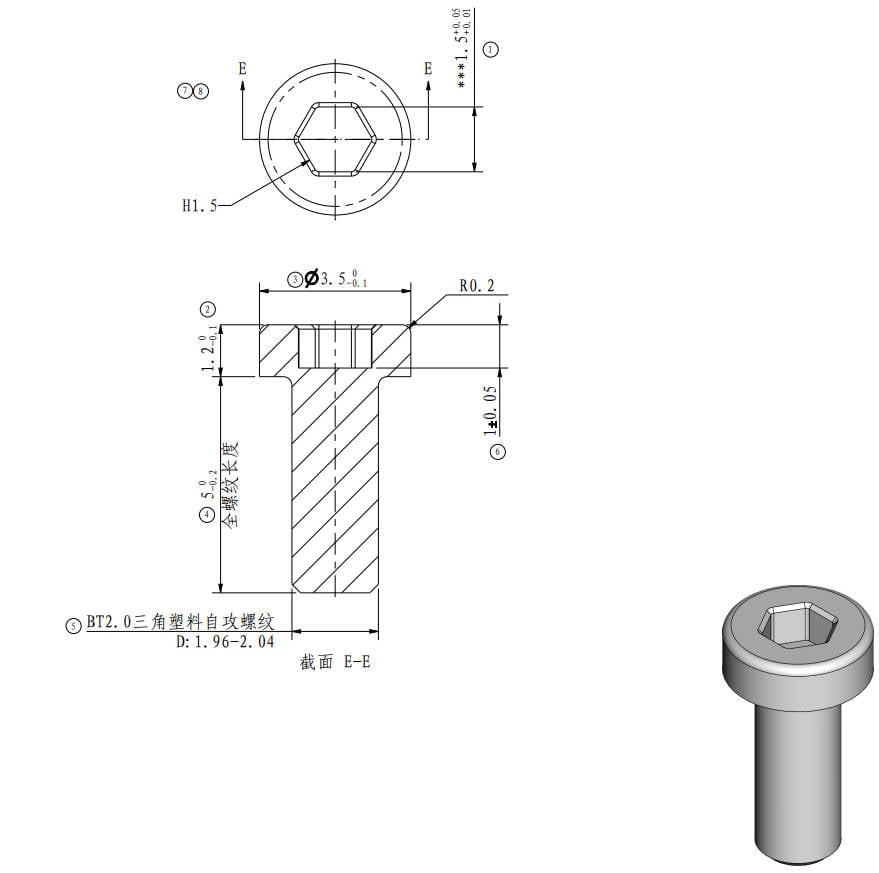
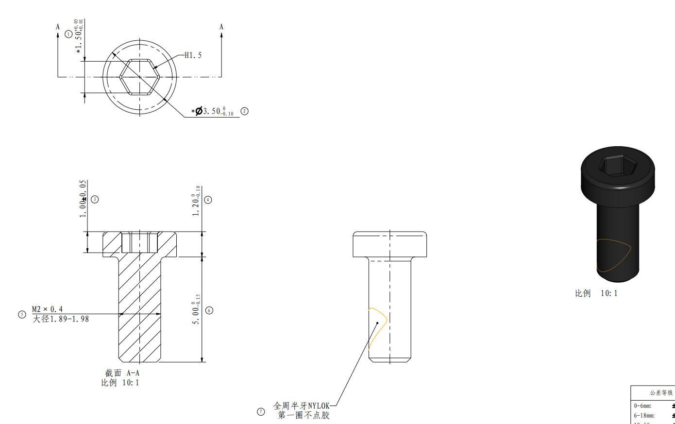
| Screw A | BT2*5 |
Toolhead housing (4PCS) |
 |
Screw B | BT2*8 | The cover of cable chain(1PCS) |
 |
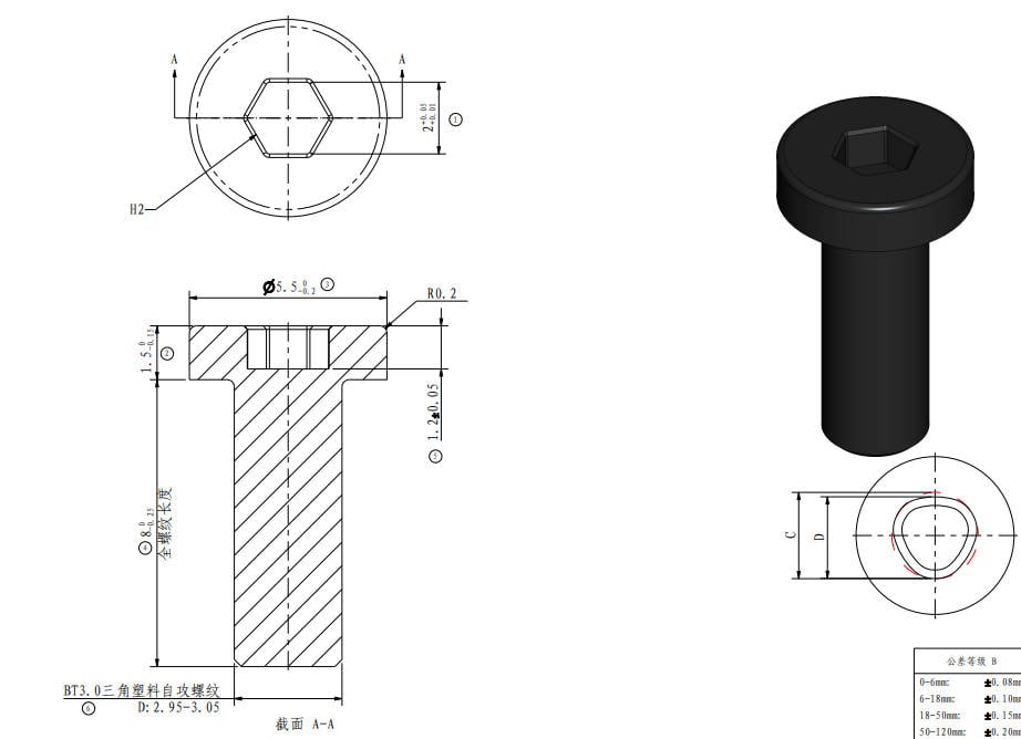
| Screw C | BT3*8 |
The lower hinge (2PCS/ 1PCS) |
 |
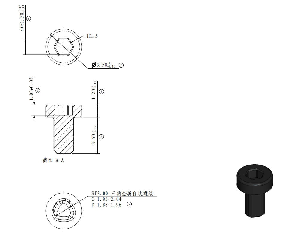
Screw D |
ST2*3.5 (2PCS) |
The Upper hinge (2PCS) |
 |
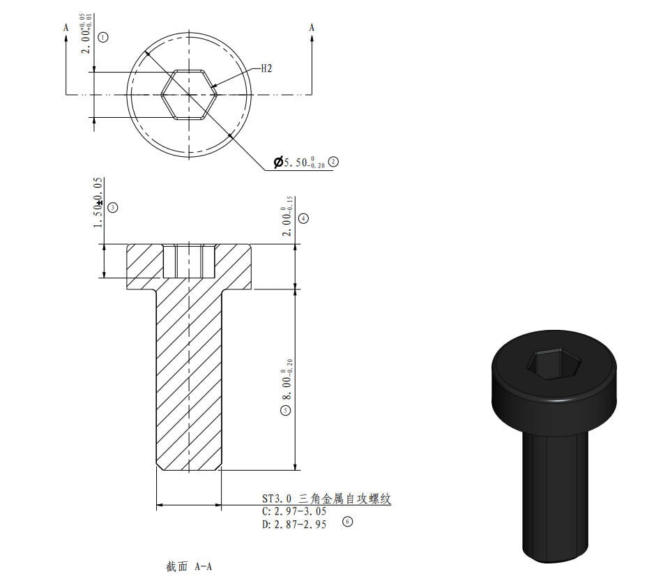
| Screw E | ST3*8 |
Spool holder (2PCS) |
 |
Screw F |
BT3*5
|
The rear panel and front cover (4PCS +1PCS) |
 |
| Screw G | ST3*4.5 |
The rear panel and front cover (9PCS +2PCS) |
 |
Screw H | BT3*6 |
The left & right panel (12PCS+ 12PCS) |
 |
| Screw I | ST3*4.5 |
The rear part of the panels (4PCS+ 4PCS) |
|
Screw J | ST2*3.5 |
The top part of the panel (4PCS+ 4PCS) |
|
| Screw K | BT3*12 |
Aux. part cooling fan (2PCS) |
 |
Screw L | M2*5 |
Heat sink (2PCS) |
 |
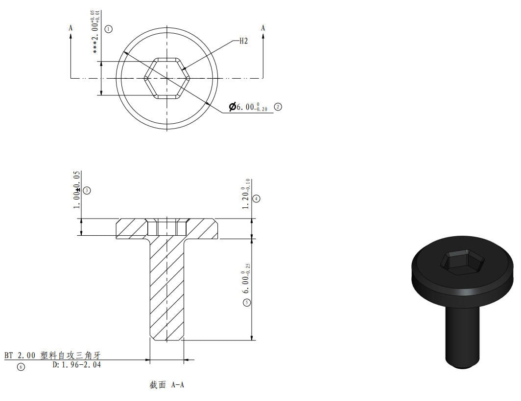
| Screw M | BT2*6 |
The air duct (3PCS) |
 |
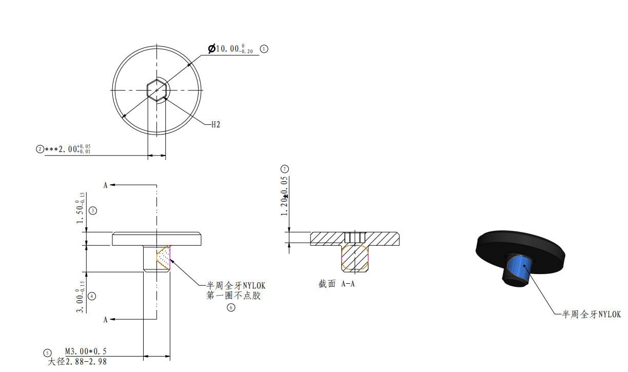
Screw N | M3*3 |
Front glass door (4PCS) |
 |
¶ Verify completion/success
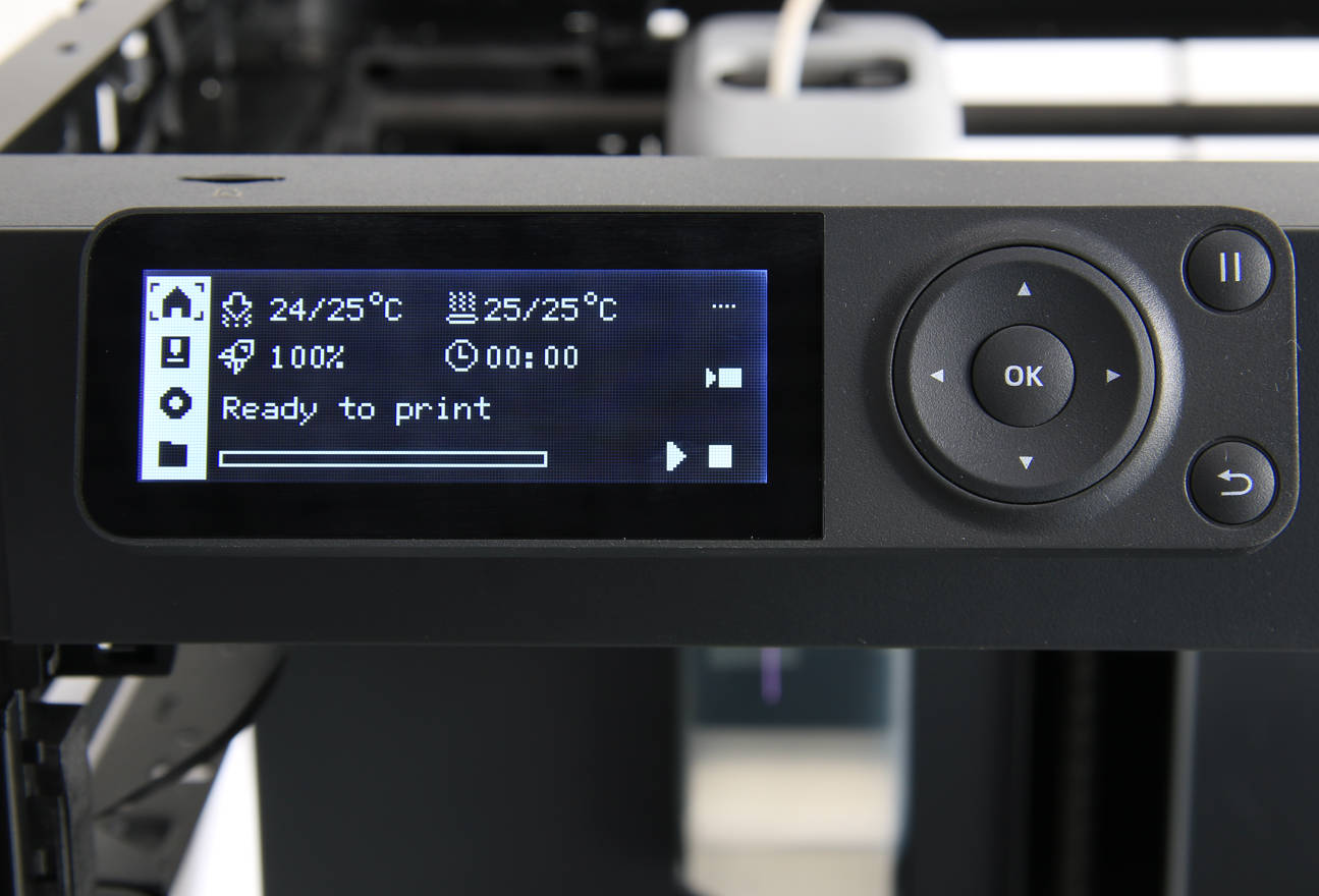
1. Power on the printer and verify that the screen is displayed normally, and the keys on it respond as expected.
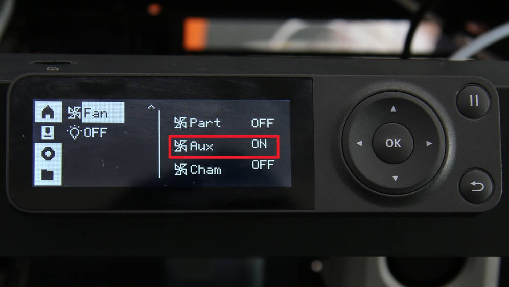
2. Click the auxiliary cooling fan icon on the screen to activate the auxiliary cooling fan. Confirm that the fan can be turned on and off normally.
¶ Calibration step after the operation
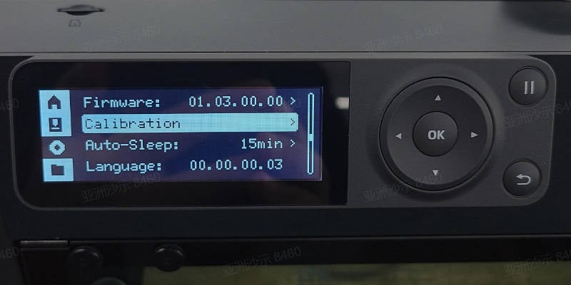
Operate on the screen, initiate a device calibration process, and confirm that the device calibration can be completed successfully and passes.
¶ End Notes
We hope the detailed guide provided has been helpful and informative.
To ensure a safe and effective execution, if you have any concerns or questions about the process described in this article, we recommend reaching out to technical support team before initiating the operation. We will do our best to respond promptly and provide the assistance you need. Click here to open a new ticket in our Support Page.