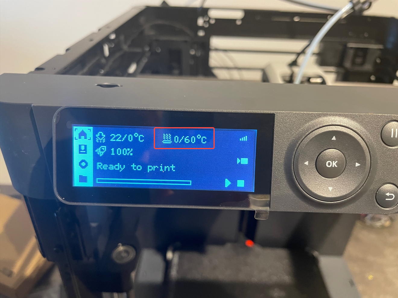
¶ Phenomenon
During the preparation for printing, the heat bed temperature does not rise, or the heat bed does not heat up after a heat bed temperature was set.
¶ Causes & Solutions
The main reasons and solutions for abnormal heatbed temperature are as follows:
- Check the resistance value of the heatbed → Abnormal → The heatbed may have burnt components or an open circuit → The heatbed needs to be replaced;
- Check the connection status of the power cable and the cable connecting the MC board with the AC power board → Poor contact → Reconnect the cable(s);
- Check the conduction of the power cable of the heatbed → The power cable is damaged → Replace the power cable (or replace the heatbed);
- Check the AC power board → The components on the AC power board are damaged (the heatbed and power cord are confirmed to be normal) → Replace the AC power board.
¶ Safety warning and Machine state before starting operation
1. The heatbed is directly heated by the mains electricity, and there is a danger of high voltage. It is necessary to ensure that troubleshooting is carried out with the power off.
2. If it is found that the heatbed (AC power board) is burnt, check whether the AC power board (heatbed) is in good condition at the same time.
¶ Tools needed
- H2.0 Allen key
- Multimeter
- Tweezers
¶ Scenario one - The heatbed temperature is displayed as 0
¶ Troubleshooting suggestions
1. Check the connection status of the heatbed NTC;
2. Check the connection status of the connection cable from the heatbed to the MC board;
Note: The connectors of these two cables are fixed with white silicone gel. If there is no obvious tilt or PIN withdrawal, just press again; When you need to disconnect them, you can use a hair dryer to heat the silicone gel to reduce the hardness and then remove the silicone gel or disconnect the cables.
¶ Operation guide (disassembly & inspection)
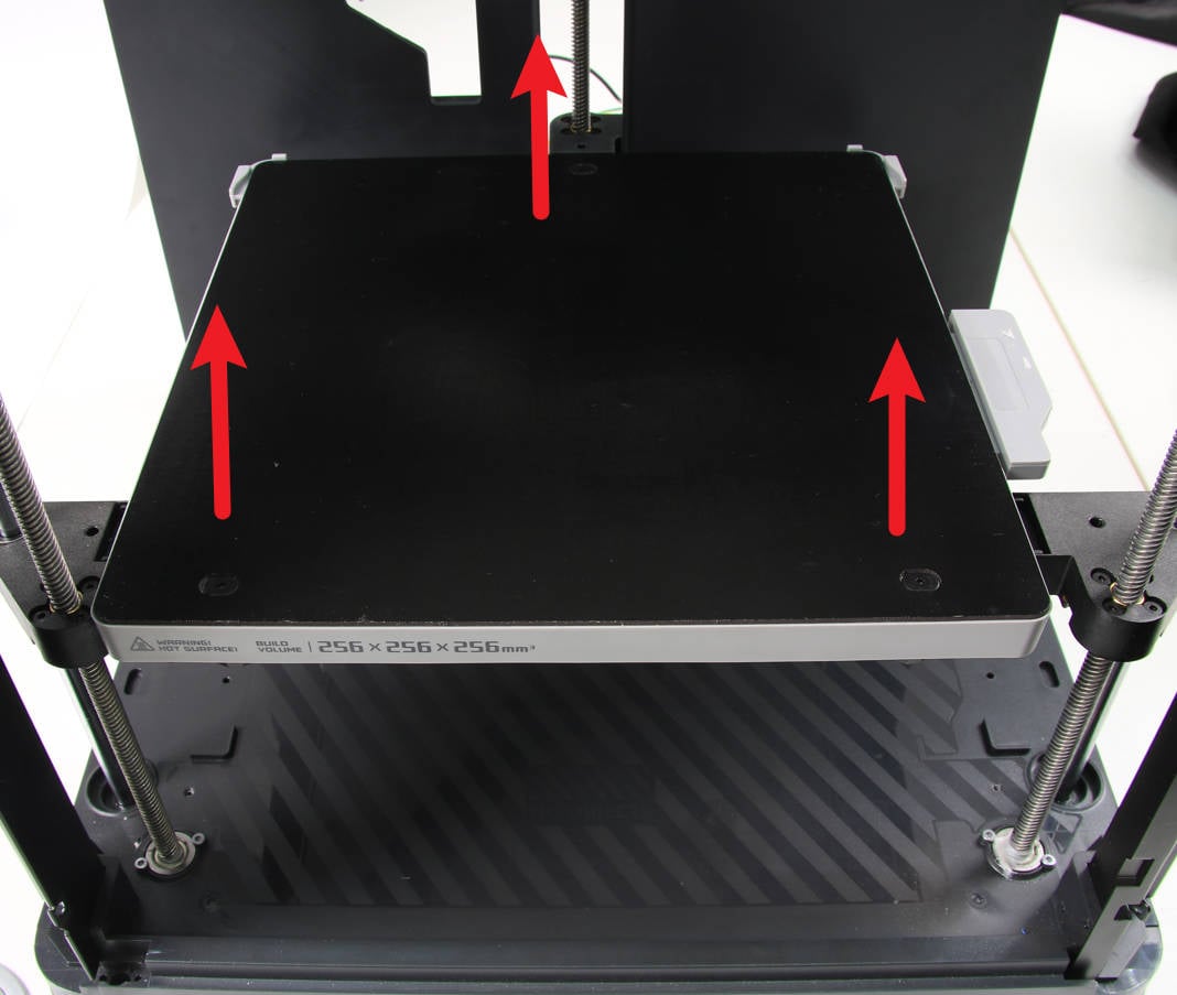
¶ Step 1 - Raise the heatbed
Tilt the printer and pull the Z-axis belt to raise the heated bed to ⅔ of the full height of the screw to make room for processing.
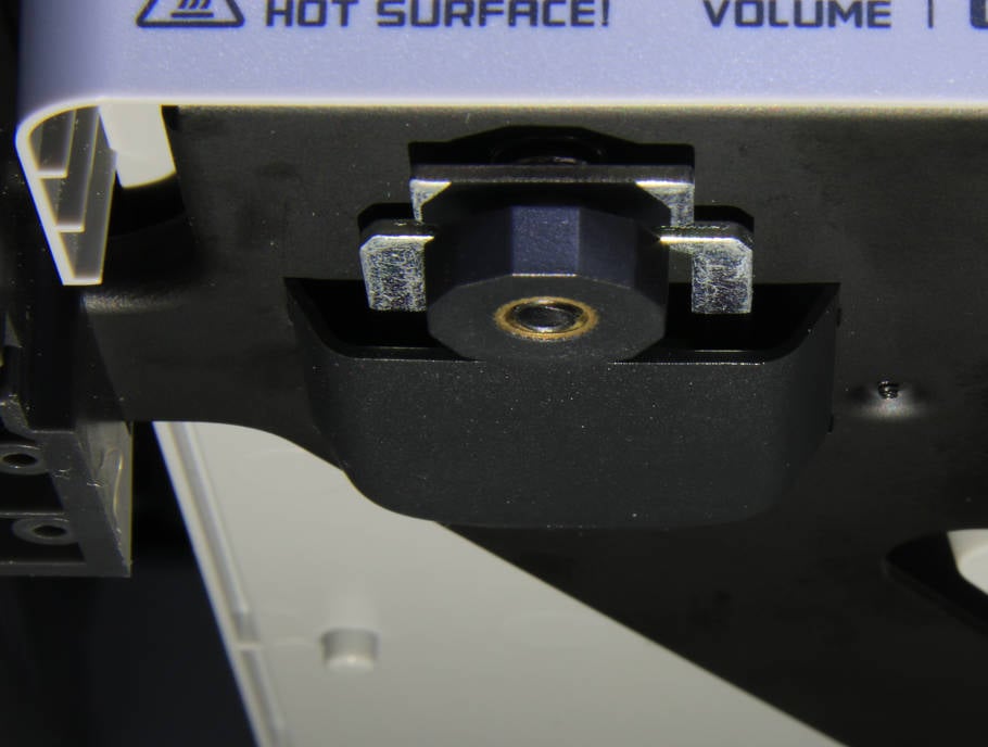
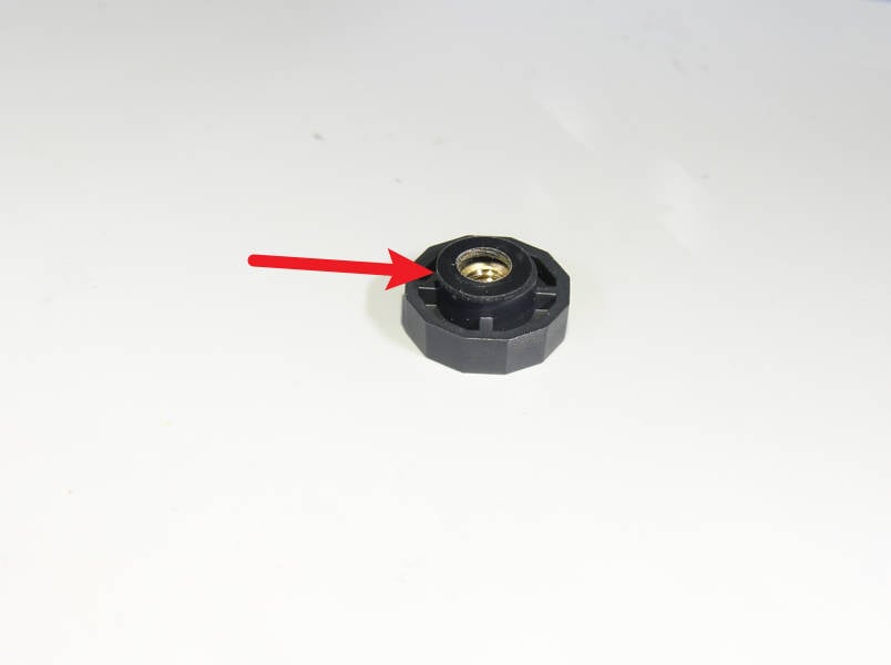
¶ Step 2 - Remove the heatbed pretension nuts
Unscrew the 3 pretension nuts to unlock the heatbed from the metal bracket. Note that there is also a rubber ring on top of each nut.
 |
 |
¶ Step 3 - Open heatbed
Open the heatbed carefully because of the cable inside, and remove the loose pretension springs.
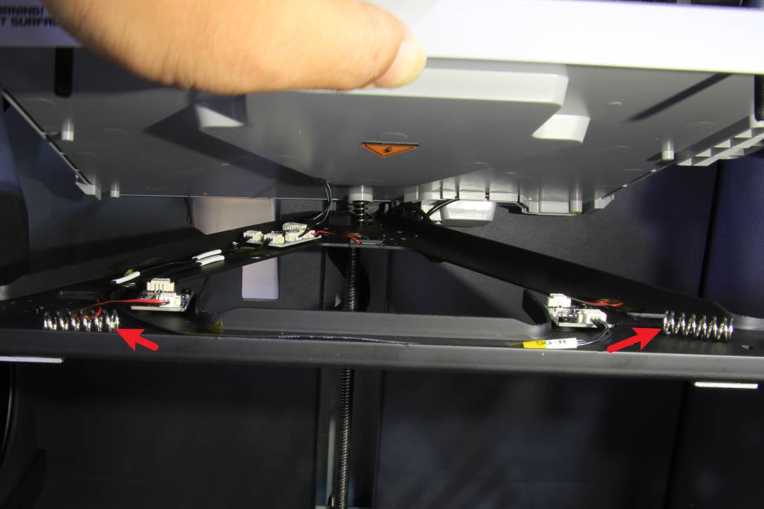
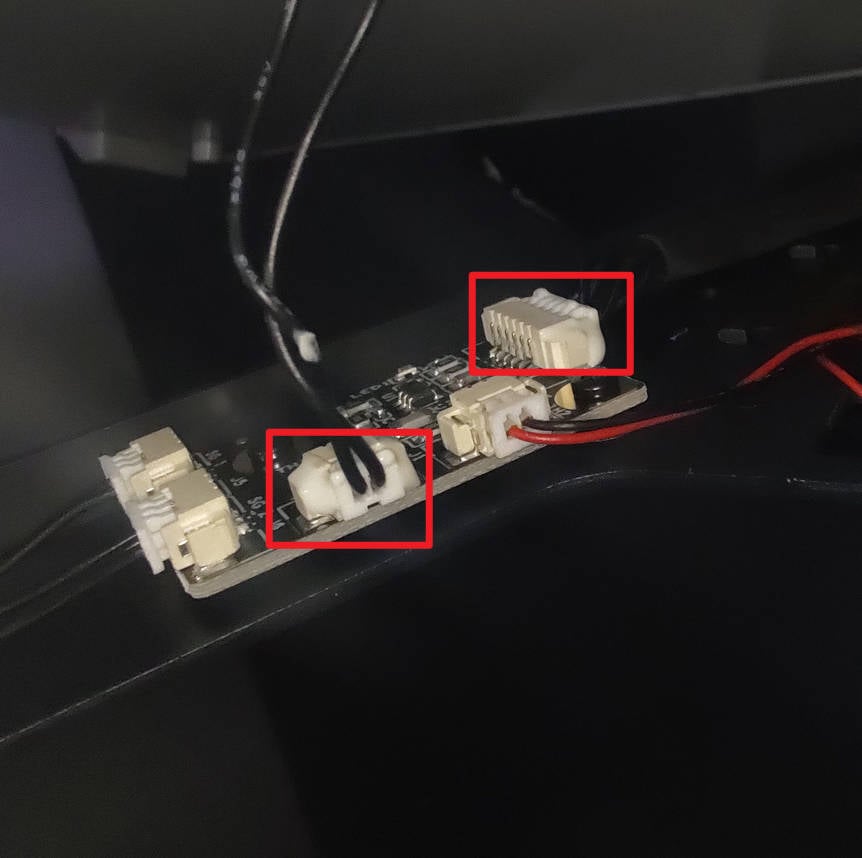
¶ Step 4 - Check the connection status
During this step, you can check the connection between the heatbed to the MC board and the NTC cable simultaneously. The 2PIN connector is for the NTC cable. It is necessary to check whether the connectors are loose and whether the cables are loose.
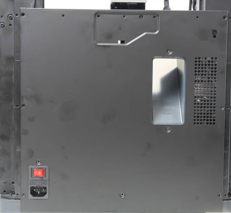
¶ Step 5 - Remove the rear panel
- Remove 4 coarse thread screws with an H2.0 Allen key.
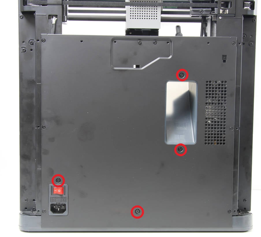
- Remove 7 fine thread screws with an H2.0 Allen key.
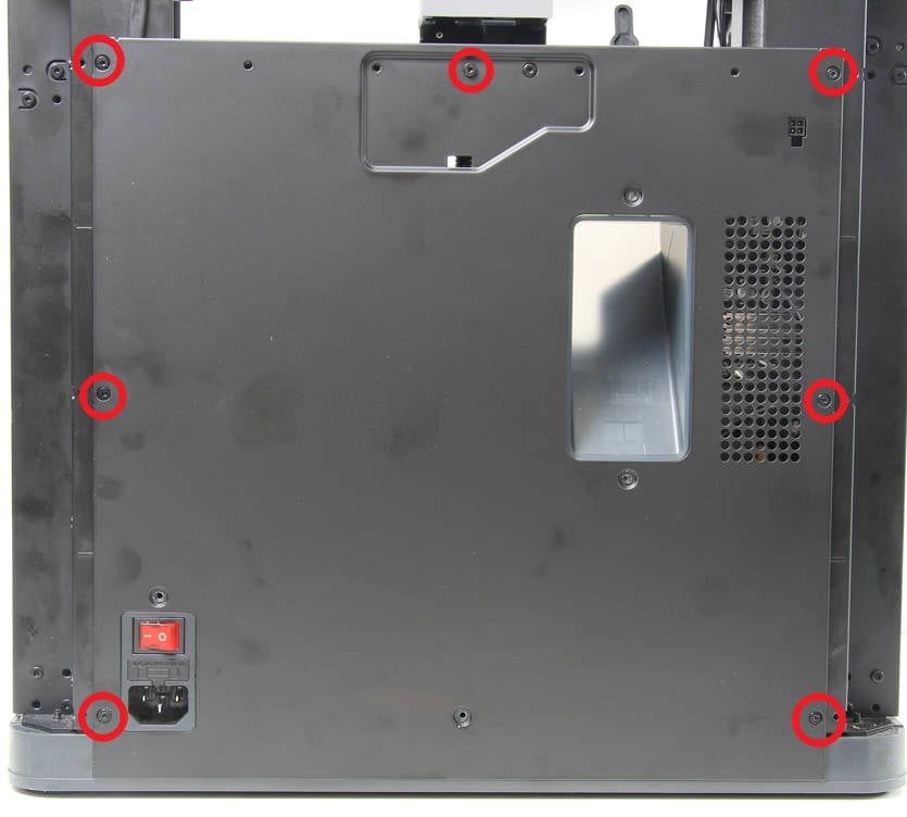
- Remove the rear panel from the printer.
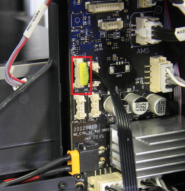
¶ Step 6 - Check the connector on MC board
Check the status of the connection cable on the MC board, and confirm that the connection is not floating and no PIN is withdrawn. After checking and confirming, you can reconnect the power supply and turn the printer on to confirm whether the heatbed temperature is no longer displayed as 0. If the fault is not eliminated, you need to check the connection status of the heatbed.
If the fault persists, you need to contact the service team for confirmation.
¶ Assembly guides
¶ Step 1 - Install the pretension springs
Hold the upper part of the heat bed, and install the pretension springs to the heat bed screws one after another.
¶ Step 2 - Mount the heatbed
Now you can close the heatbed and mount them together. Gently press from the top of the heat bed, and confirm that all three stubs can pass through the holes on the sensor holder.
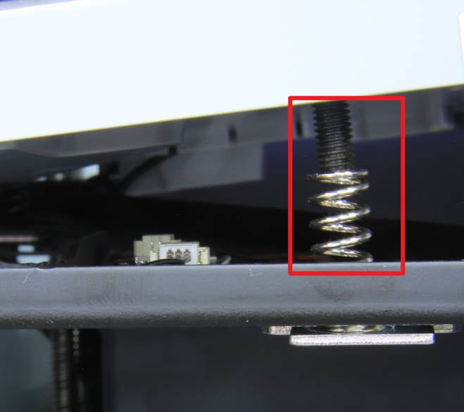
¶ Step 3 - Lock the pretension nuts
Place the rubber ring on the 3 pretension nuts and then screw them in evenly, a little at a time. DO NOT lock them yet. Continue to screw in the nuts evenly, until the studs are flush with the bottom of the nuts (see picture below).
|
 |
¶ Setp 4 - Install the rear panel
- Install the rear panel to the back of the printer;
- Lock in 7 fine-thread screws;
- Lock in 4 coarse-thread screws.
¶ Scenario two - The heatbed temperature is not displayed as 0
This situation is usually caused by abnormal power supply to the heatbed, which causes the heatbed to fail to heat up.
¶ Troubleshooting Suggestions
-
Check the connection status of the heatbed power cable;
-
Check the output of the AC board (High voltage, electrician basics are required).
¶ Operation guide (disassembly & inspection)
¶ Step 1 - Raise the heatbed
In order to facilitate this process, we need to raise the heatbed: tilt the printer, and pull the Z-axis belt to raise the heatbed to 2/3 of the way up.
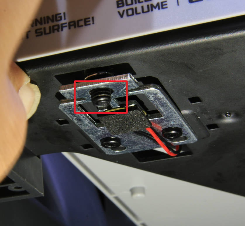
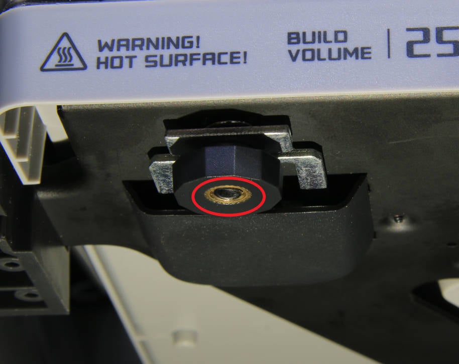
¶ Step 2 - Check the resistance of the heatbed
Remove the 2 screws as shown in the picture below, remove the cover, and use a multimeter to test the resistance value of the two terminals. If the resistance value is between 40 and 60 ohms, the heatbed is normal, and you can go to the next step; otherwise, the heatbed needs to be replaced. Please refer to Heatbed.
 |
 |
¶ Step 3 - Remove the rear panel
- Remove 4 coarse thread screws with an H2.0 Allen key.
- Remove 7 fine thread screws with an H2.0 Allen key.
- Remove the rear panel from the printer.
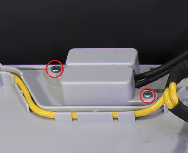
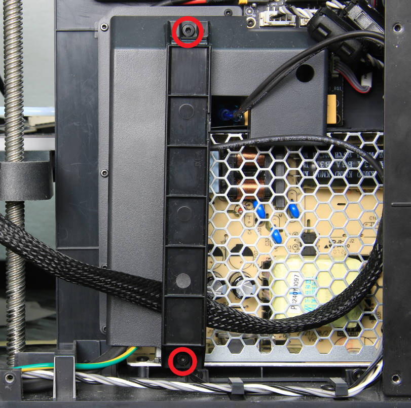
¶ Step 4 - Remove the cable cover
Use an H2.0 Allen key to remove the 2 screws and remove the cable cover.
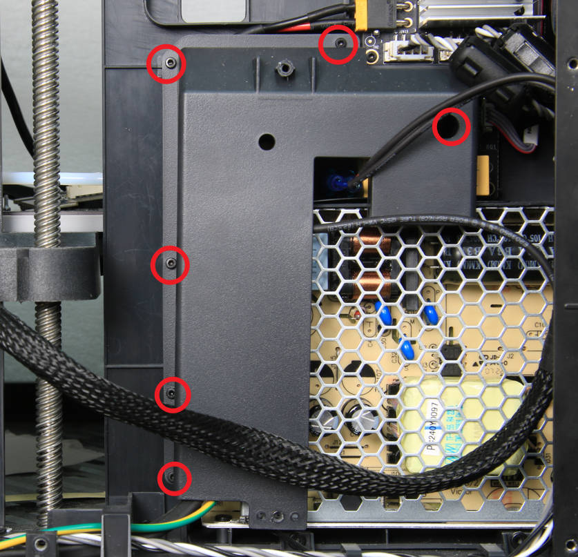
¶ Step 5 - Remove the cable holder
Use an H1.5 Allen wrench to remove the 6 screws and remove the cable holder.
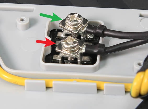
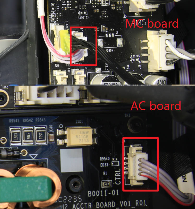
¶ Step 6 - Check the cable connections
Check the connection status of the power cable and the cable connecting the MC board with the AC power board to confirm that the connection is normal without looseness or skew. Then, go to the next step.
 |
 |
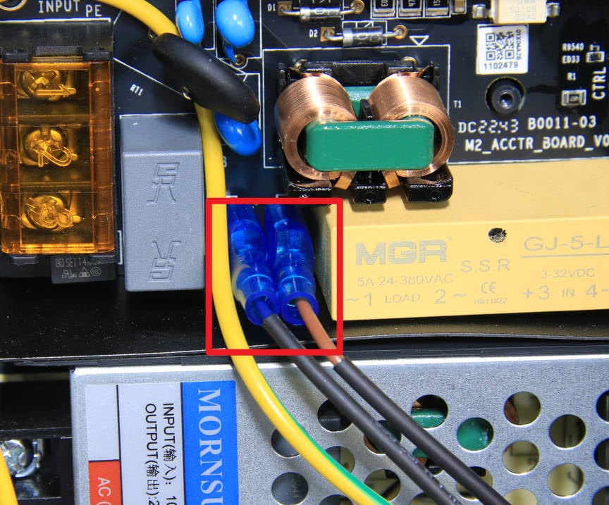
¶ Step 7 - Check the heatbed power cable
Remove the two blue silicone sleeves and test the resistance value with a multimeter.
- If the resistance value is between 40 and 60 ohms, the power cable is normal, and you can go to the next step.
- If the value is different, it means that the power cable is faulty and needs to be replaced (or the heatbed needs to be replaced). Please refer to Heatbed.
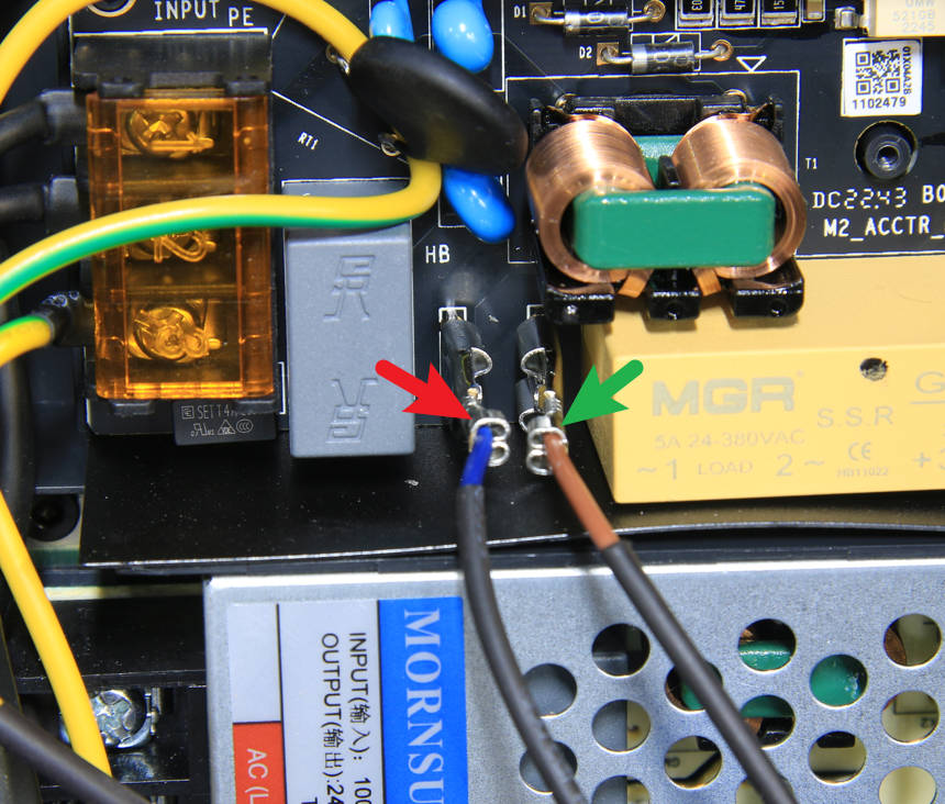
Caution: After measuring, please restore the blue silicone sleeves to keep the plugs insulated.
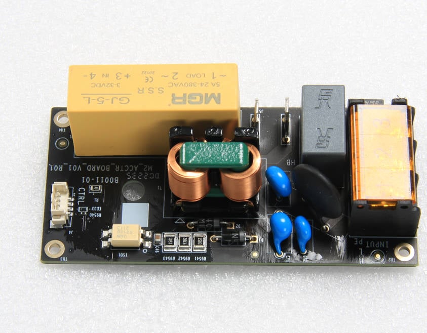
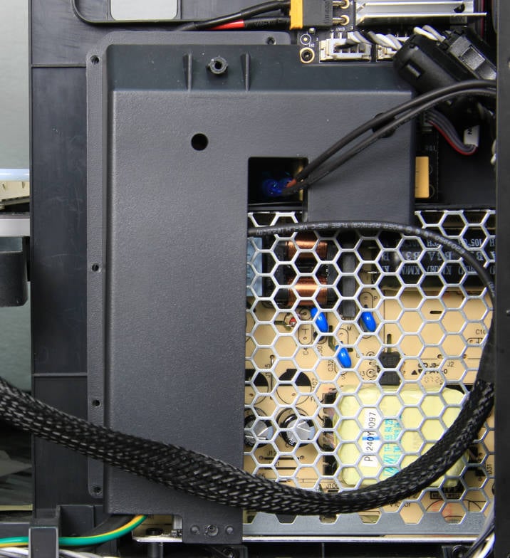
¶ Step 8 - Check the AC power board
If the above steps are normal, it can be confirmed that the AC power board is faulty and must be replaced.
Of course, if the AC power board has visible damage, this can also be used to determine that the AC power board is damaged and needs to be replaced. Please refer to AC board.
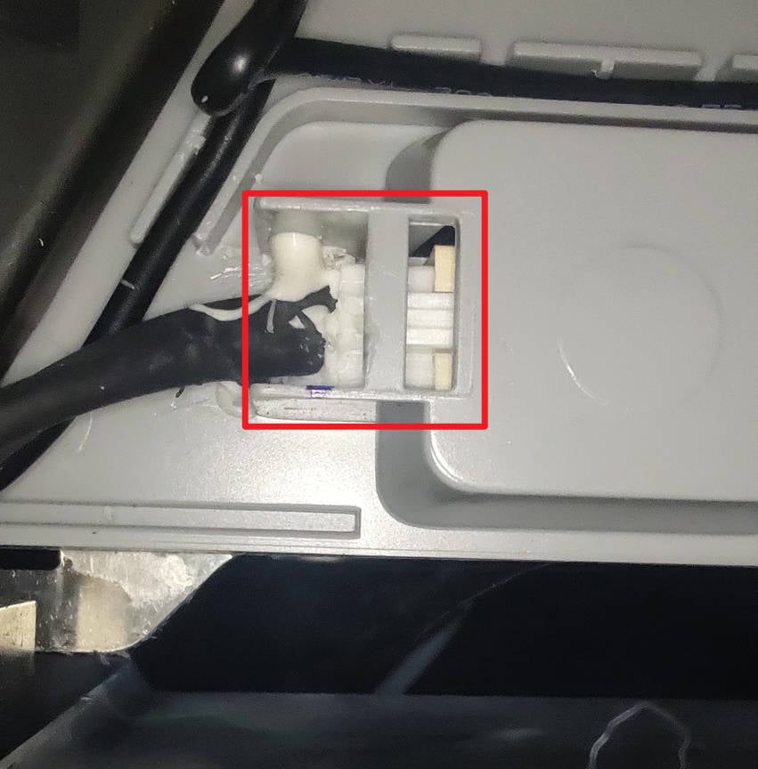
¶ Step 9 - Check the power cord connection under the heatbed
Warning: Make sure to disconnect the power cord before operation.
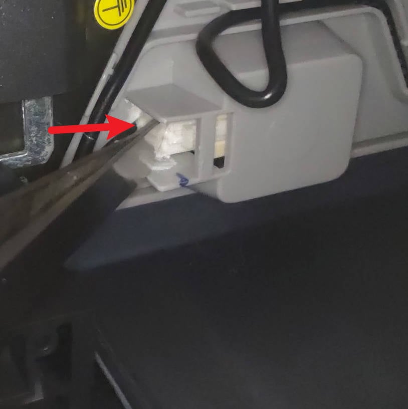
The connector is usually coated with white silicone, so it may not be directly visible whether it is connected properly. Just use tweezers to try to push the connector to the interface several times.
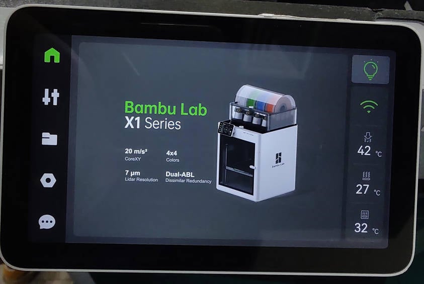
After pressing, connect the power supply to start the printer, set the bed temperature to confirm whether the problem is solved.
If the problem is not solved, continue to the next step to check the AC board output.
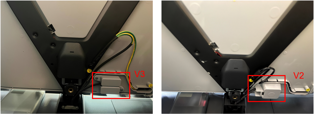
 |
 |
Note: Differences between V2 and V3 versions of the heatbed:
¶ Step 10: Check the appearance of the AC power board
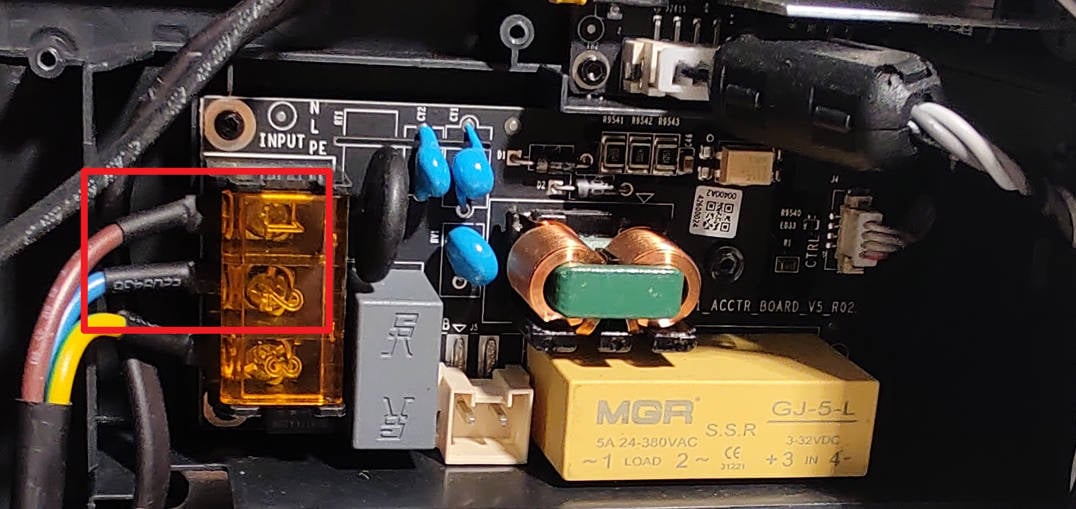
Visually inspect the appearance of the AC board, including shaking to check if the power input line is loose (if so, reconnect and fix it), and whether there are obvious signs of burnout on the components on the board (if so, please refer to Replace the AC power boardReplace the AC power board). If there is no abnormality, proceed to the next step.
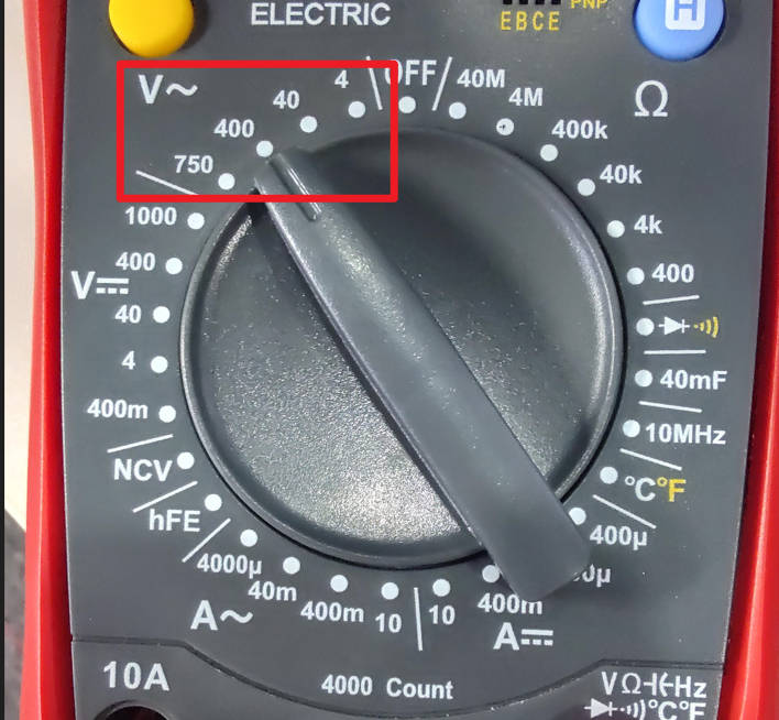
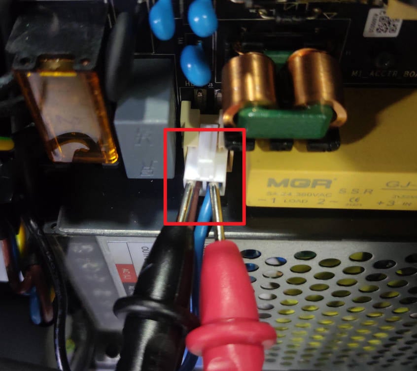
¶ Step 11: Check the AC board voltage output
Warning: This operation detects the mains voltage. It is not recommended for people without relevant knowledge to avoid danger.
When printer is turned on, use the AC voltage test file of the multimeter to check the output voltage. This voltage should be the same as the local voltage. If the output voltage is abnormal, it means that there is a problem with the AC board. Please refer to Replace the AC power board to replace the AC board.
 |
 |
If the above operations cannot eliminate the fault, you need to contact after-sales for confirmation.
¶ Assembly guides
¶ Install the cable holder
Install the cable holder on the printer, avoid the cables, and tighten the 6 screws.
 |
|
¶ Install the cable cover
Install the cable cover and tighten the 2 screws.
¶ Install the back panel
- Install the rear panel to the back of the printer;
- Lock in 7 fine-thread screws;
- Lock in 4 coarse-thread screws.
P1S Please refer to: Replace the Rear Metal Panel - P1 Series
¶ End Notes
We hope the detailed guide provided has been helpful and informative.
If this guide does not solve your problem, please submit a technical ticket, we will answer your questions and provide assistance.
If you have any suggestions or feedback on this Wiki, please leave a message in the comment area. Thank you for your support and attention!