Beam Interlocking is a feature that adds additional layers between two or more materials during multi-material 3D printing. When you enable it, it stitches different materials together by inserting tiny bridges or beams of one material into the other, creating a physically linked seam.
Normally, slicers handle multi-material models by assigning different parts of a mesh to different extruders or AMS slots. The problem? Some materials, such as TPU and PLA, even if printed perfectly, don’t bond well. This can cause your print to delaminate at the seams with just a small amount of pressure. Before we explore how to access this feature and its various settings, let's examine its benefits in detail.
¶ Benefits of Beam Interlocking Feature in Bambu Studio
¶ 1. Ensures There is a Stronger Bond Between Rigid and Flexible Materials
Beam Interlocking physically anchors the two materials together using small beam structures that cross the boundary between them. This provides both mechanical grip and thermal adhesion, reducing the risk of parts peeling, delaminating, or separating under stress or movement.
For example, in the simple cube below, this is how it looks before applying Beam interlocking.
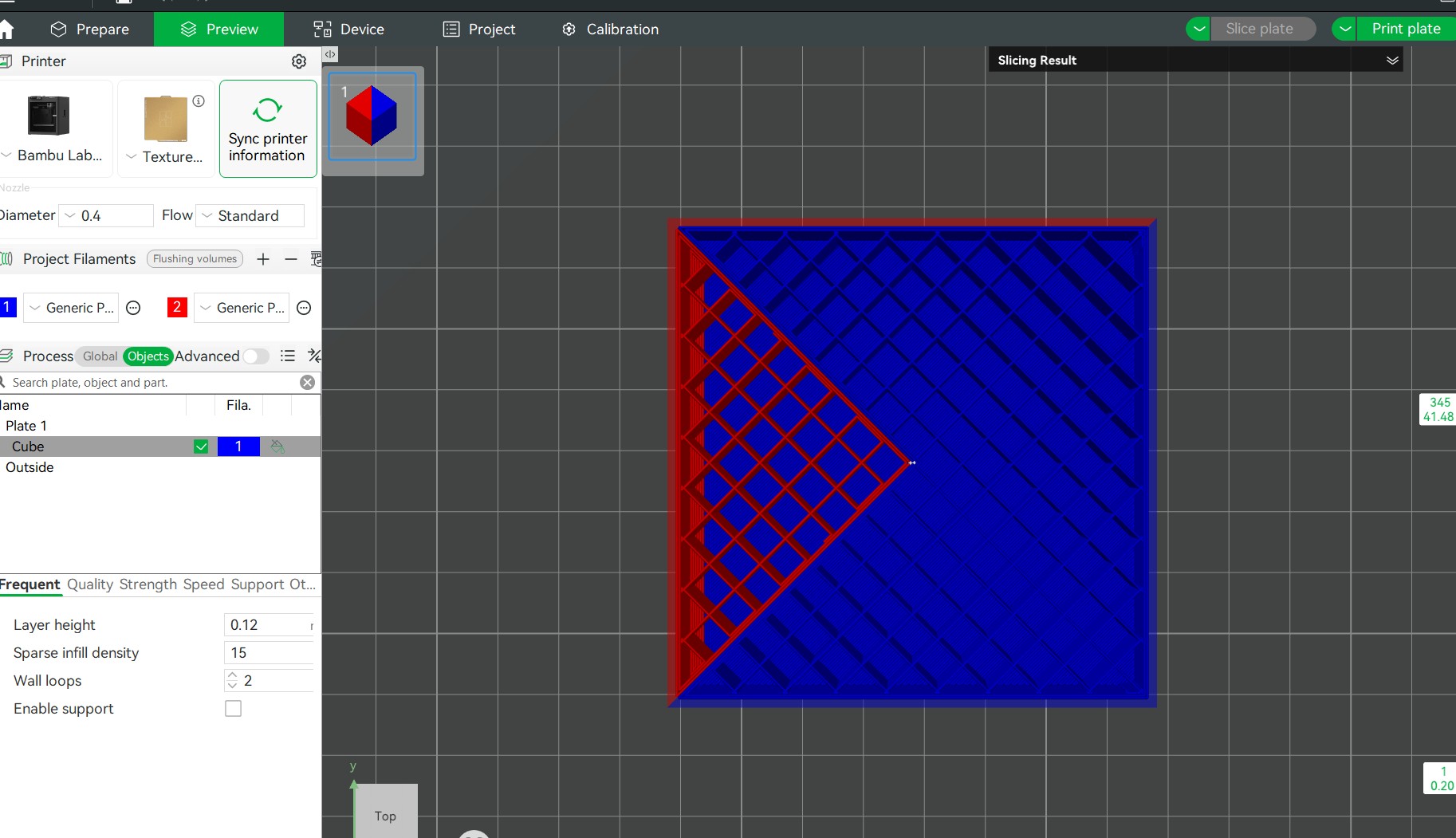
After activating the Beam Interlocking, it looked like this:
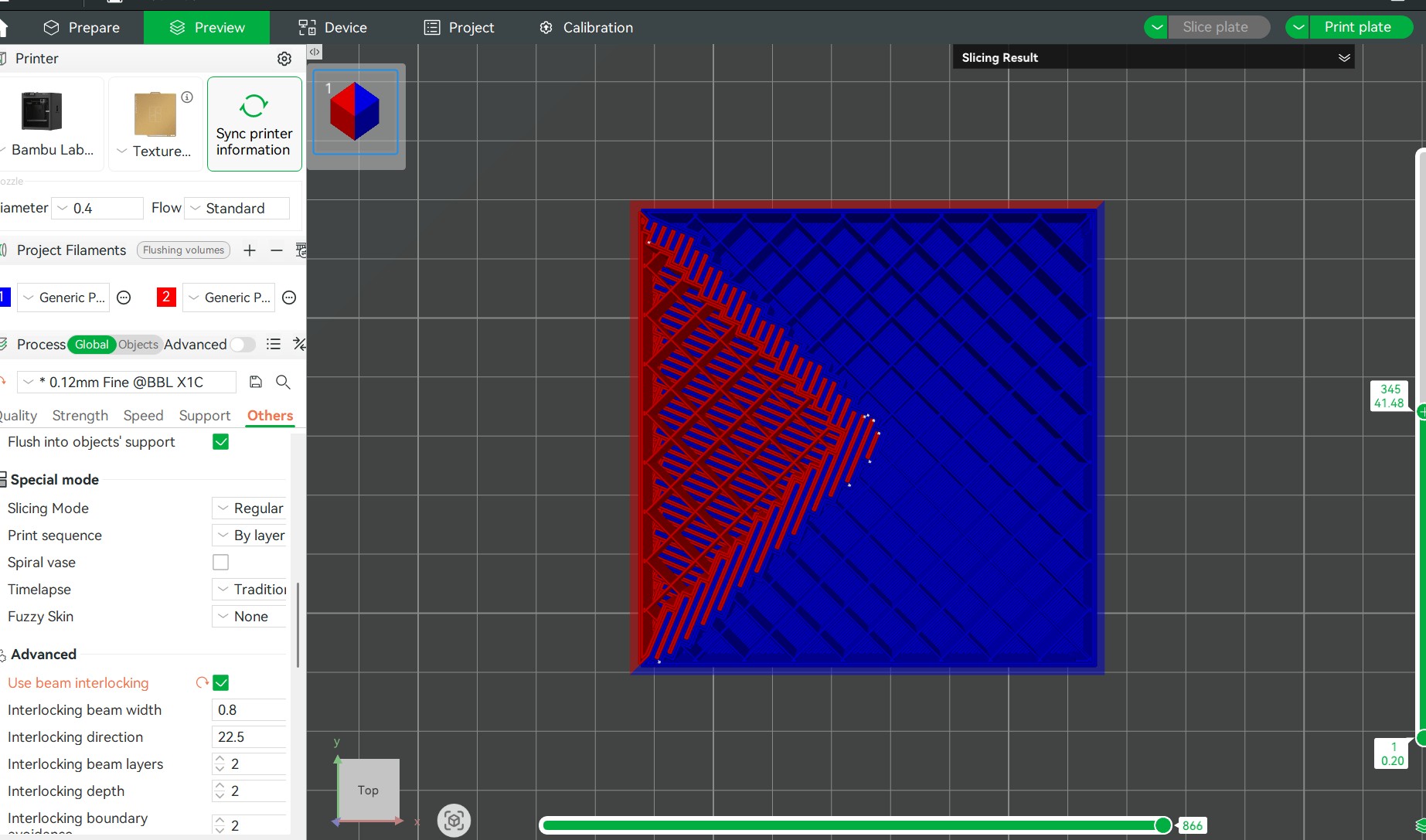
If you look keenly, you will realize, there are additional elements added where the two materials meet.
Without Beam Interlocking, the TPU sides may peel off over time, especially when pulling the phone in and out of your pocket. With Beam Interlocking enabled, the soft TPU edges are mechanically fused into the PETG part, making the case much more durable and resistant to wear.
¶ 2. Enhanced Durability and Longevity
Because we are not extruding continuously across the build plate, structural integrity may suffer when printing the object with different materials, and the adjacent extrusions might be potentially weaker. Beam Interlocking strengthens these weak points, resulting in longer-lasting prints, particularly for items subjected to flexing, pressure, or handling, such as tool grips, phone mounts, or wearables.
¶ 3. Greater Design Freedom
You can confidently create designs meant for 3D printing with different materials confidently knowing that they will stay connected. This is especially helpful in functional assemblies like snap-fits, or soft joints that would otherwise require glue or screws. You won't also worry about the file failing to print when using different materials, because some parts may detach.
¶ 4. Ensures Joints are Seamless
Beam interlocking ensures joints are tightly fitted and aesthetically clean, and it reduces the appearance of seams. This is great for presentation models, cosplay props, or any project where a professional finish is important.
¶ How to Access Beam Interlocking in Bambu Studio
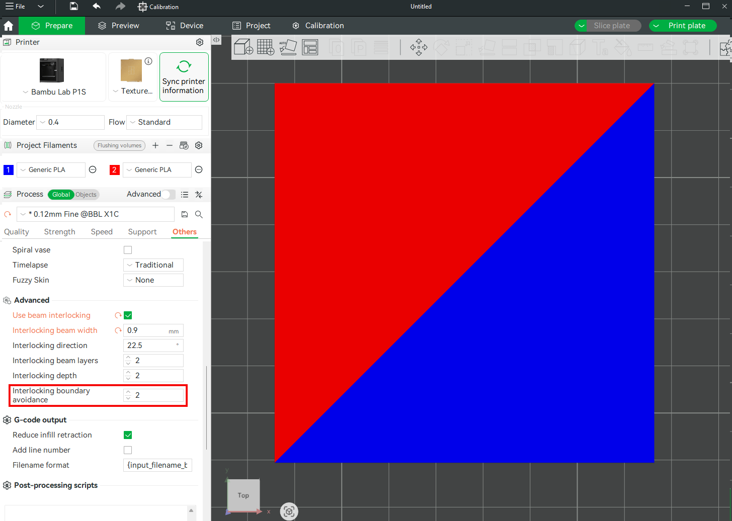
To access Beam Interlocking setting, click Global, then select Others. You will be able to see Use Beam Interlocking in the Advanced section.
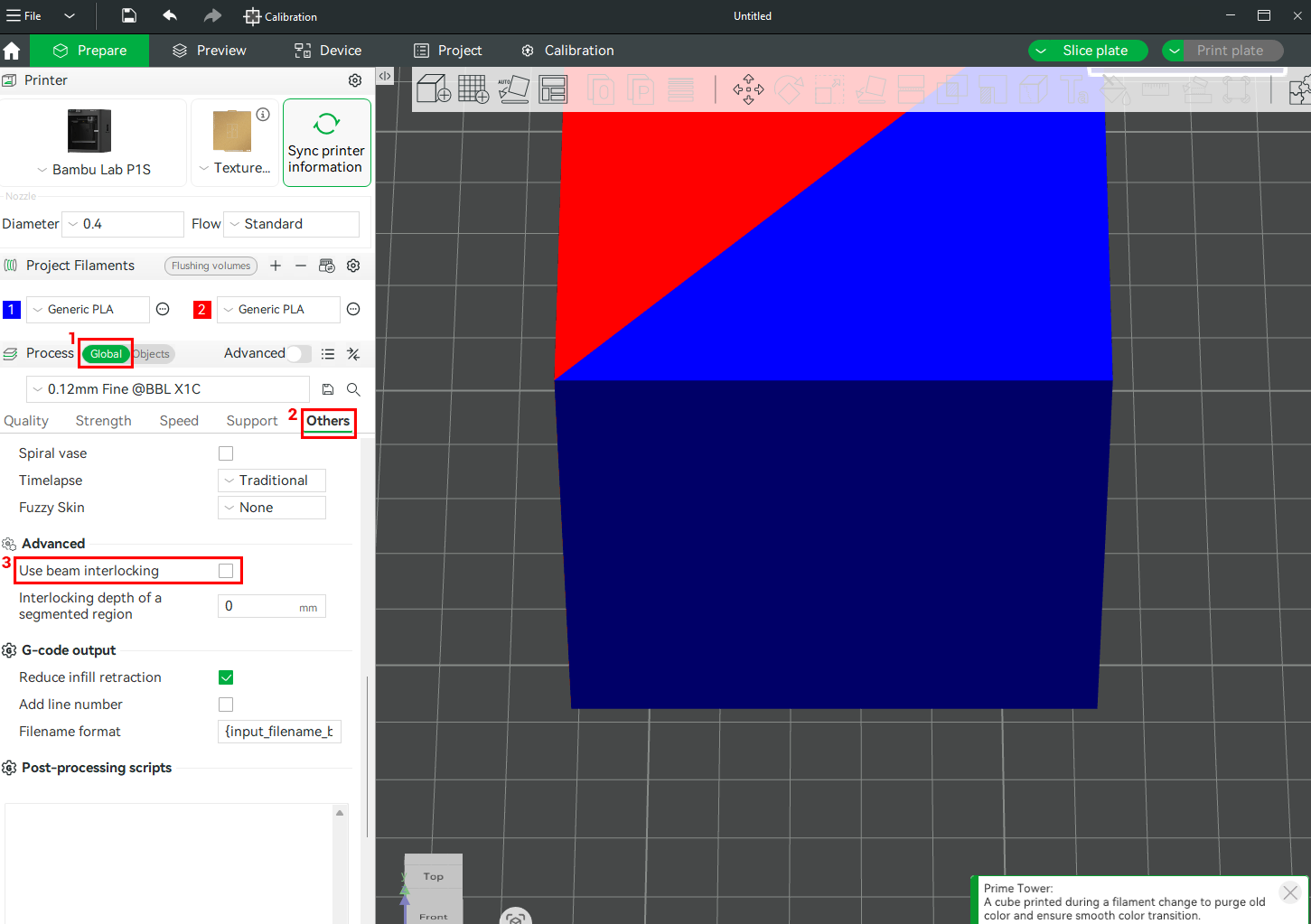
When you click the checkbox for Use Beam Interlocking, various settings will appear. These include: Interlocking beam width, Interlocking direction, interlocking beam layers, interlocking depth, and interlocking boundary avoidance.
¶ Beam Interlocking Settings
Each of the Beam Interlocking settings and their functionalities are described in detail below.
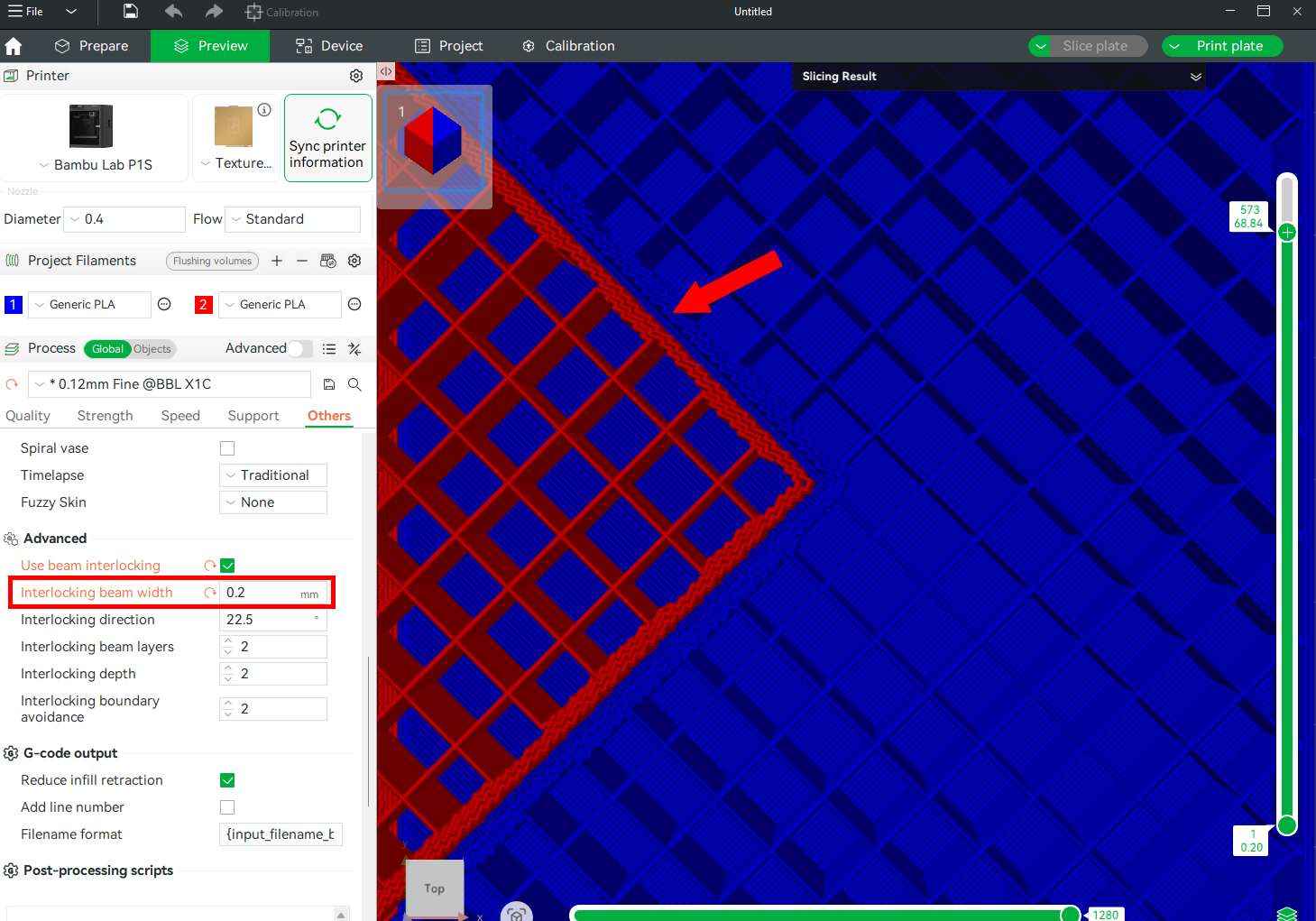
¶ 1. Interlocking Beam Width
This setting determines the thickness or width of each individual interlocking beam. A wider beam means more surface area and potentially better mechanical grip, but it also consumes more space and might interfere with the part’s design if too large. For smaller prints like, a narrower width of between 0.4–0.8 mm is often ideal to maintain design detail while still achieving a secure bond. For our example design, which we are 3D printing with PLA, PETG, and TPU, since PETG and PLA are both rigid but differ slightly in flexibility and adhesion, and TPU is very soft, we need to optimize the beam width for a solid grip without hindering flexibility. The default value is 0.8 mm, which we also used in our example above and it worked great. If we reduce the value to, say, 0.2 mm, the bond will be very weak, and it will even cause the flexible TPU membrane to detach. Below, you can see additional layers were added but are too thin.
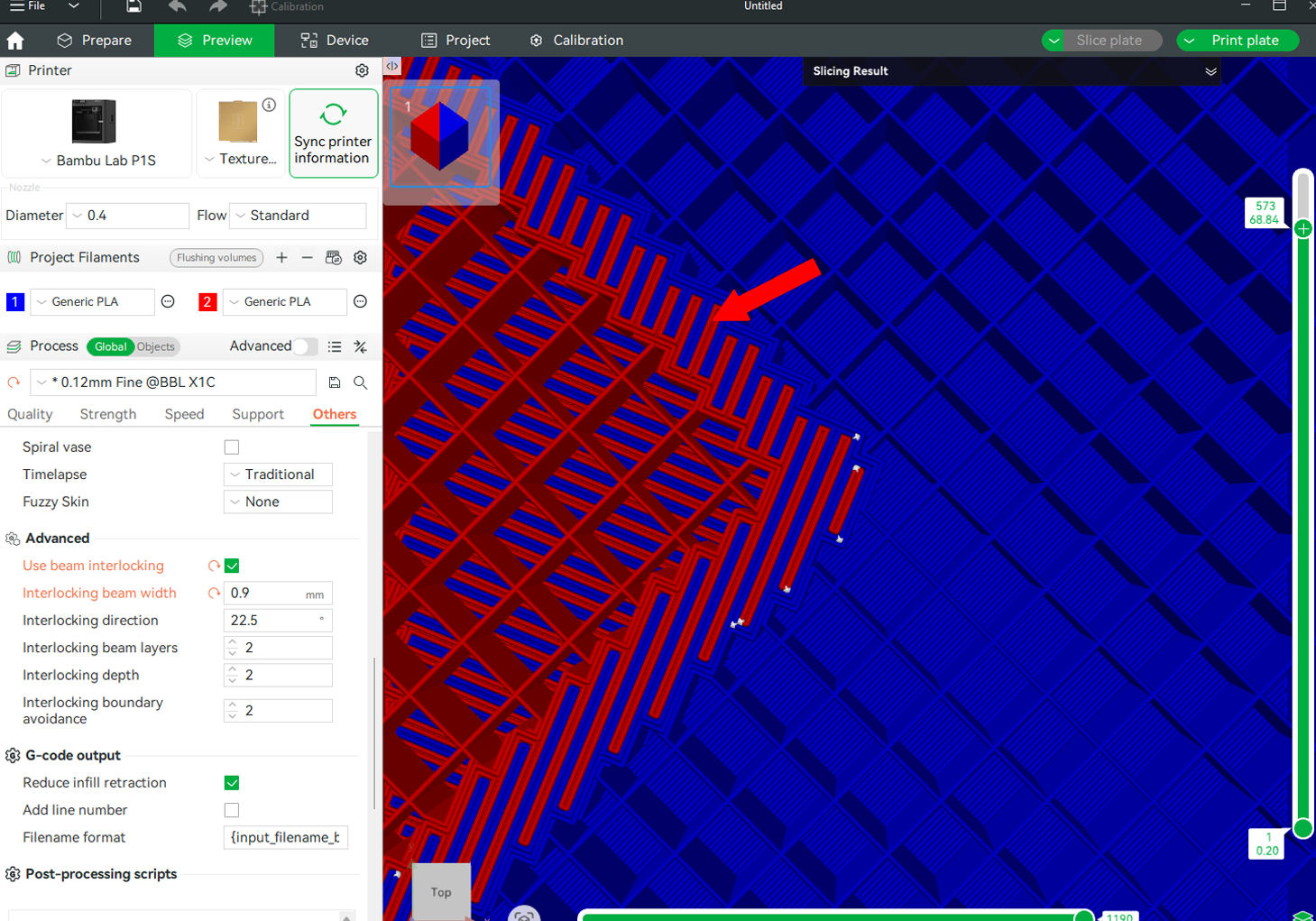
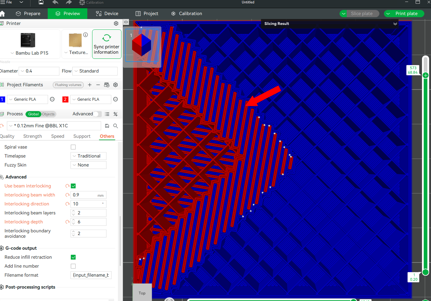
Too wide beams will make the connection become stronger. The image below shows the preview of the file after increasing the interlocking beam width to 0.9 mm. You will realize they are thicker and spaced too, as compared to the one for 0.2 mm.
¶ 2. Interlocking Direction

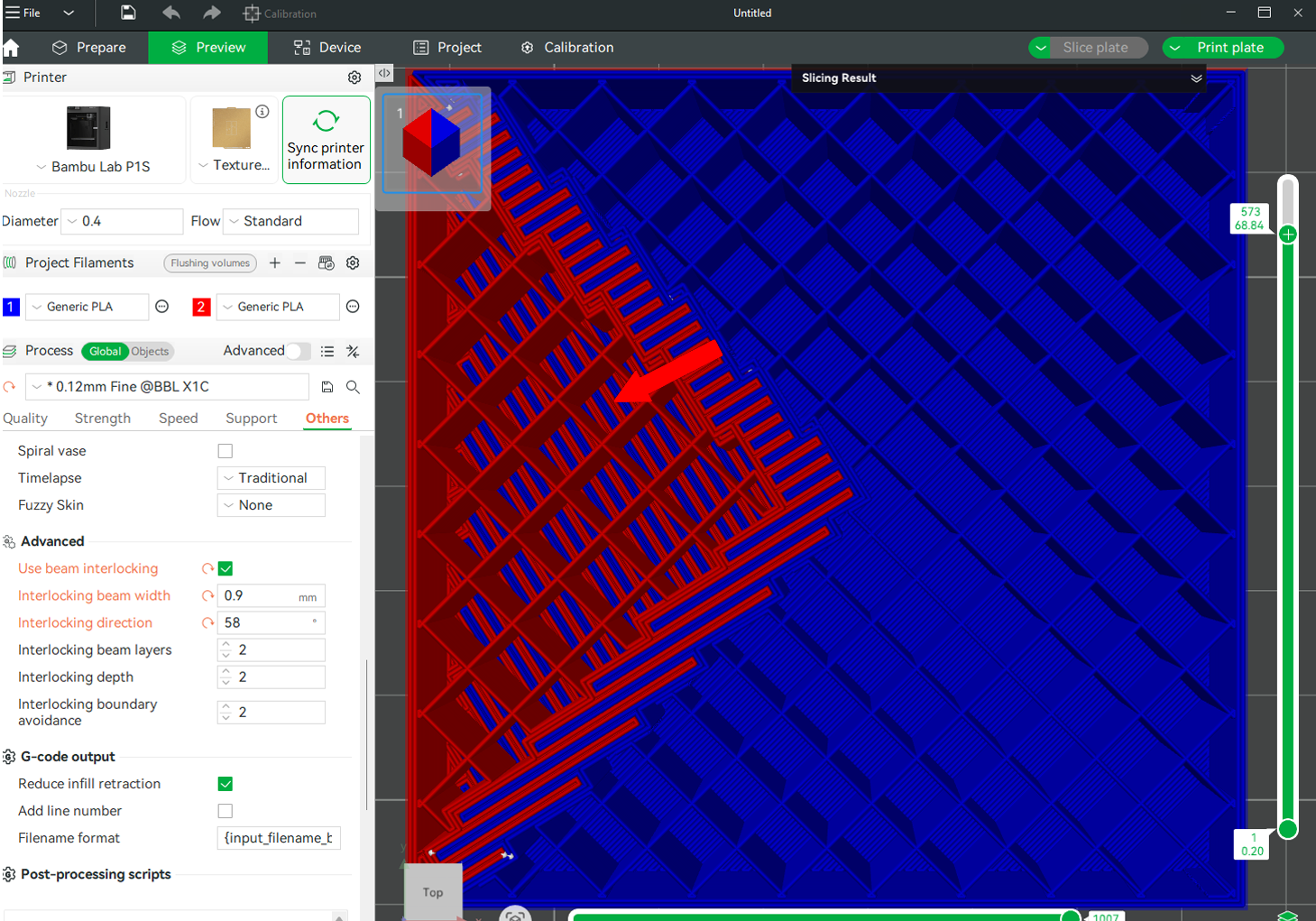
It determines the orientation or axis along which the interlocking beams are generated. The default angle is 22.5 degrees, which means the beams are slightly slanted rather than being perfectly vertical or horizontal. For our example, this default angle works perfect as it reinforces the bond between the flexible TPU middle and the rigid top and bottom shells, while still allowing the TPU to flex as needed during use. If we change the angle to other values, like 58 degrees, it will look like this.
After reducing the angle to 10 degrees, it will be as shown below.
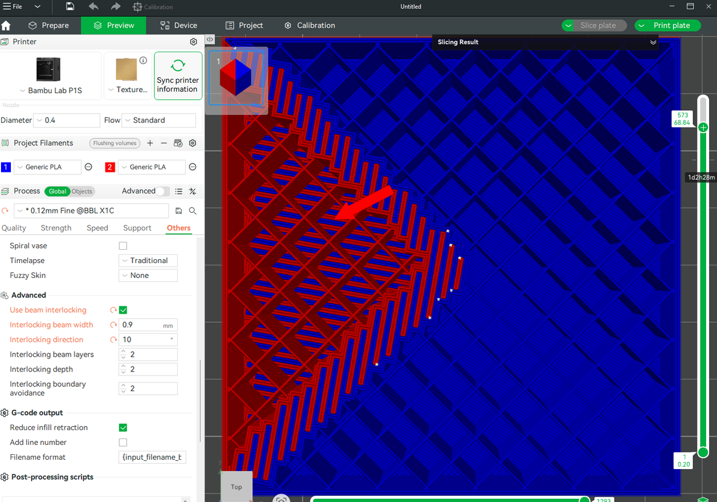
You can see there is a difference in the size and direction of the added layer material.
¶ 3. Interlocking Beam Layers

This setting determines the height of the beams of the interlocking structure, that is, the number of layers for printing each beam. Fewer layers mean a stronger bond, but this is prone to defects in most cases. More layers will result in a weaker bond, but it's more dependable. It's recommended to leave the value at 2, unless you have tested another value that's more appropriate.
¶ 4. Interlocking Depth
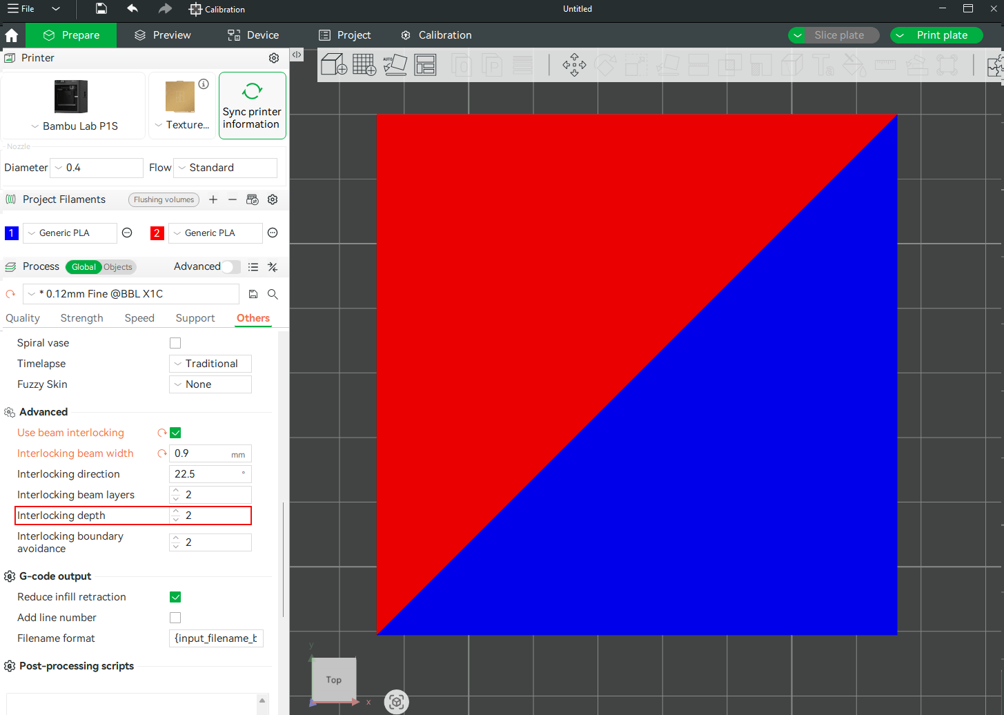
The Interlocking Depth measures how far the layers penetrate into the material, that is, the distance from the boundary to generate materials for the interlocking structures. The default value is 2, and you can increase it by clicking the up icon, and decrease it by clicking the icon pointing downwards. Slicing and previewing with the default value is shown below.

When we increase the value to 6, you will see it will now interlock much higher into the new material, and also the number of layers formed is higher too.
The default value of 2 works well in most cases; however, you can run tests to determine the optimal value that best suits your specific design. You should remember that changing the interlocking depth can sometimes affect the number of filament changes.
¶ 5. Interlocking Boundary Avoidance
This setting controls how far the beam interlocking infill stays away from the model’s outer walls.
Below is the preview when the value is 1.
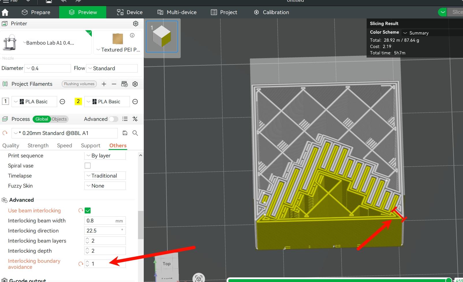
In the above, you notice the beams are coming relatively close to the wall, providing good structure. This balances strength and surface quality.
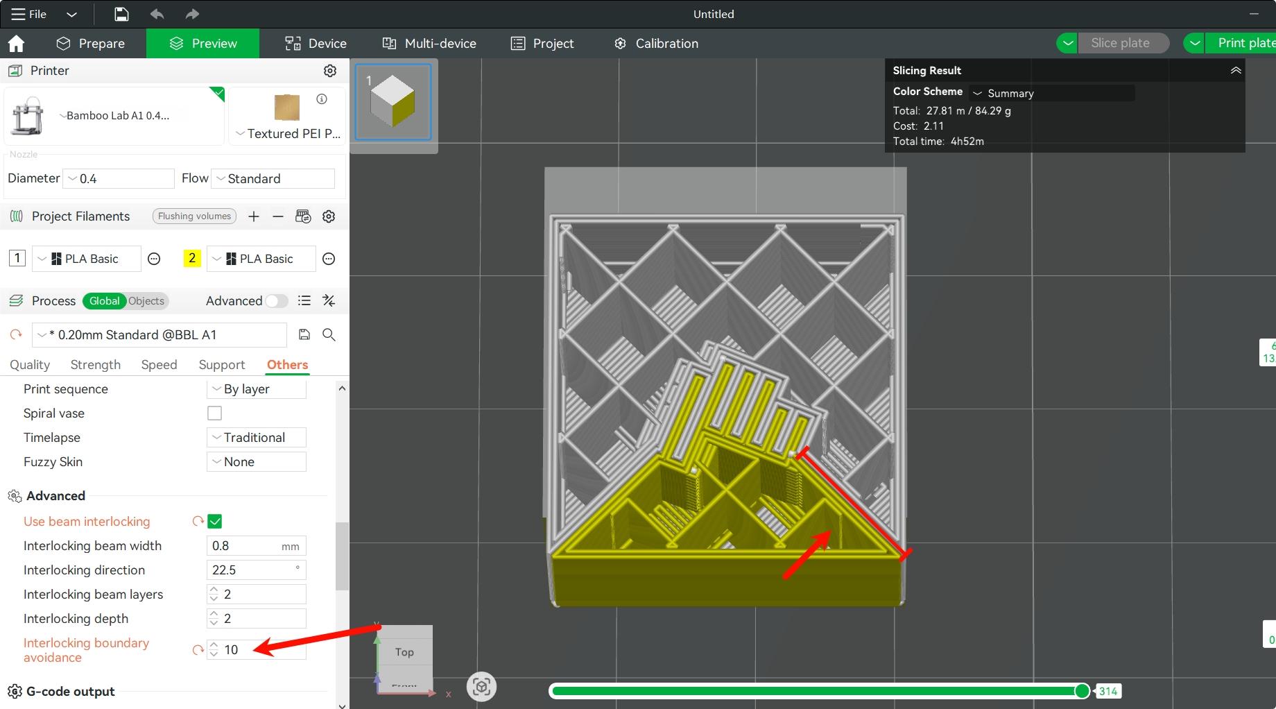
When we increase it to 10, you will realize the beams are heavily pushed inward, and a large margin is left between the infill pattern and the model’s walls. This option prioritizes wall surface appearance, but reduces strength at the edges.
¶ Key Things to Note When Using Beam Interlocking
When using Beam Interlocking, you should take note of the following:
-
Check wall thickness and internal geometry: Ensure there is sufficient internal space for the beam structures to form correctly. Additionally, surrounding walls must be sufficiently thick to maintain their strength. For thin walls or highly detailed surfaces, adjust the interlock beam layers and beam depth to prevent damage to critical features.
-
Optimize alignment and interlocking direction: Ensure the parts are oriented or aligned perpendicular to the beam direction for optimal results.
-
Consider material compatibility: Choose the materials that easily bond together. TPU and PETG can bond easily, and they adhere during printing. You should also avoid pairing materials with poor bonding characteristics, like TPU and standard PLA, as they often suffer from layer separation or weak adhesion, especially at the corners. It's also important to do a test print before doing a major 3D print.
¶ End Notes
We hope the detailed guide provided has been helpful and informative.
To ensure a safe and effective execution, if you have any concerns or questions about the process described in this article, we recommend submitting a technical ticket regarding your issue. Please include a picture or video illustrating the problem, as well as any additional information related to your inquiry.