¶ Special mode - Slicing Mode
The Special Slicing Mode in Bambu Studio determines how the slicer interprets and processes the geometry of your 3D model before generating G-code. It affects how surfaces, holes, and shells are handled, especially in models that have unusual structures, open edges, or overlapping geometry.
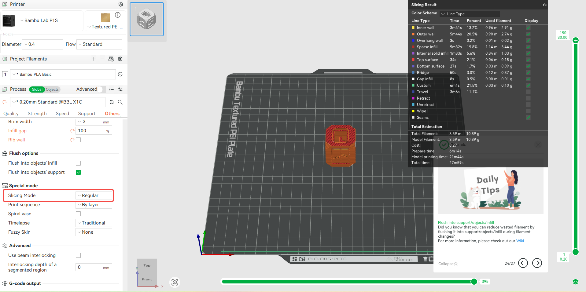
Slicing Mode is found in the Others > Special Mode section.

The available options include Regular, Even-Odd and Close Holes. Each of these modes is designed to address specific characteristics of the model. To use them, you select the option, then go ahead and slice the model.
¶ Regular Mode
This is the default option, which you can use for standard 3D models with clean, manifold geometry. It processes the 3D models based on standard mesh rules, assuming your model is watertight (manifold), has no open edges, and adheres to design principles.
- Applicable models: Regular models;
- Unsuitable models: Models with complex internal features, like wing ribs in RC planes, especially if those features are non-solid or self-intersecting. In such cases, the standard algorithm may not produce toolpaths that match the intended design. Hence, you will need to switch to Even-odd mode.
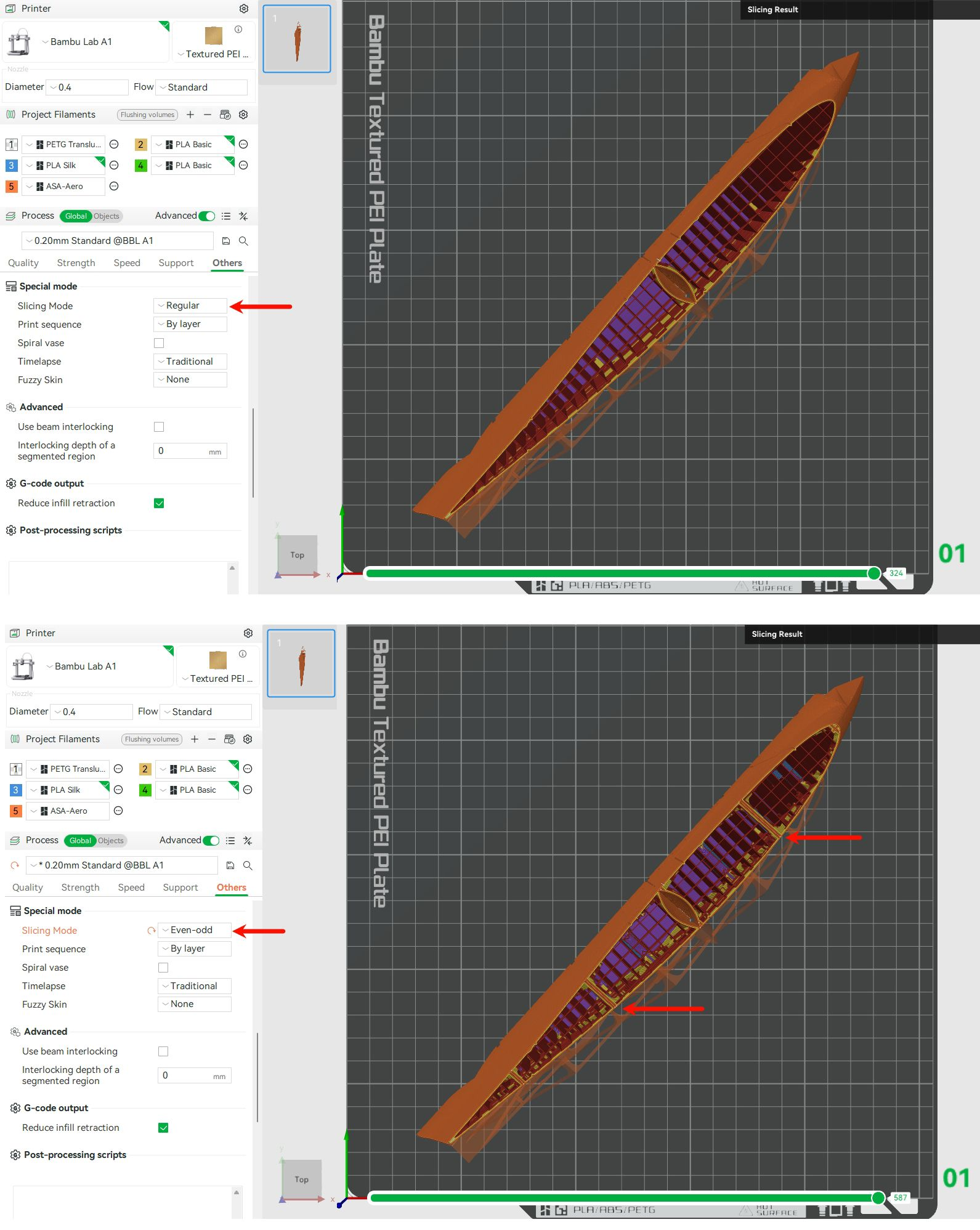
¶ Even-Odd Mode
The Even-Odd slicing mode is specifically designed for specialized 3D models like RC cars, drones, and airplanes that rely on thin, intersecting surfaces to create internal structures. These models are often built with a single perimeter and no infill, resulting in extremely lightweight components that are ideal for applications where reducing weight is crucial for optimal performance.

Traditional slicers struggle with these designs due to overlapping or non-manifold geometry, often interpreting them as broken models. Additionally, they may over-extrude or under-extrude when dealing with such narrow geometries, which can lead to weak or inconsistent walls. The Even-Odd mode addresses this issue by accurately interpreting closed contours, distinguishing between solid and hollow regions, and ensuring the correct toolpaths are generated for precise print areas.
A good example of the category of 3D models that benefit from this feature is the 3DLabPrint files, and those from similar sites. They are specifically designed for thin-wall printing, and often use a modeling technique where the walls are made of overlapping shells with shared edges, creating complex geometry that may confuse a slicer’s default interpretation of what’s “inside” or “outside.
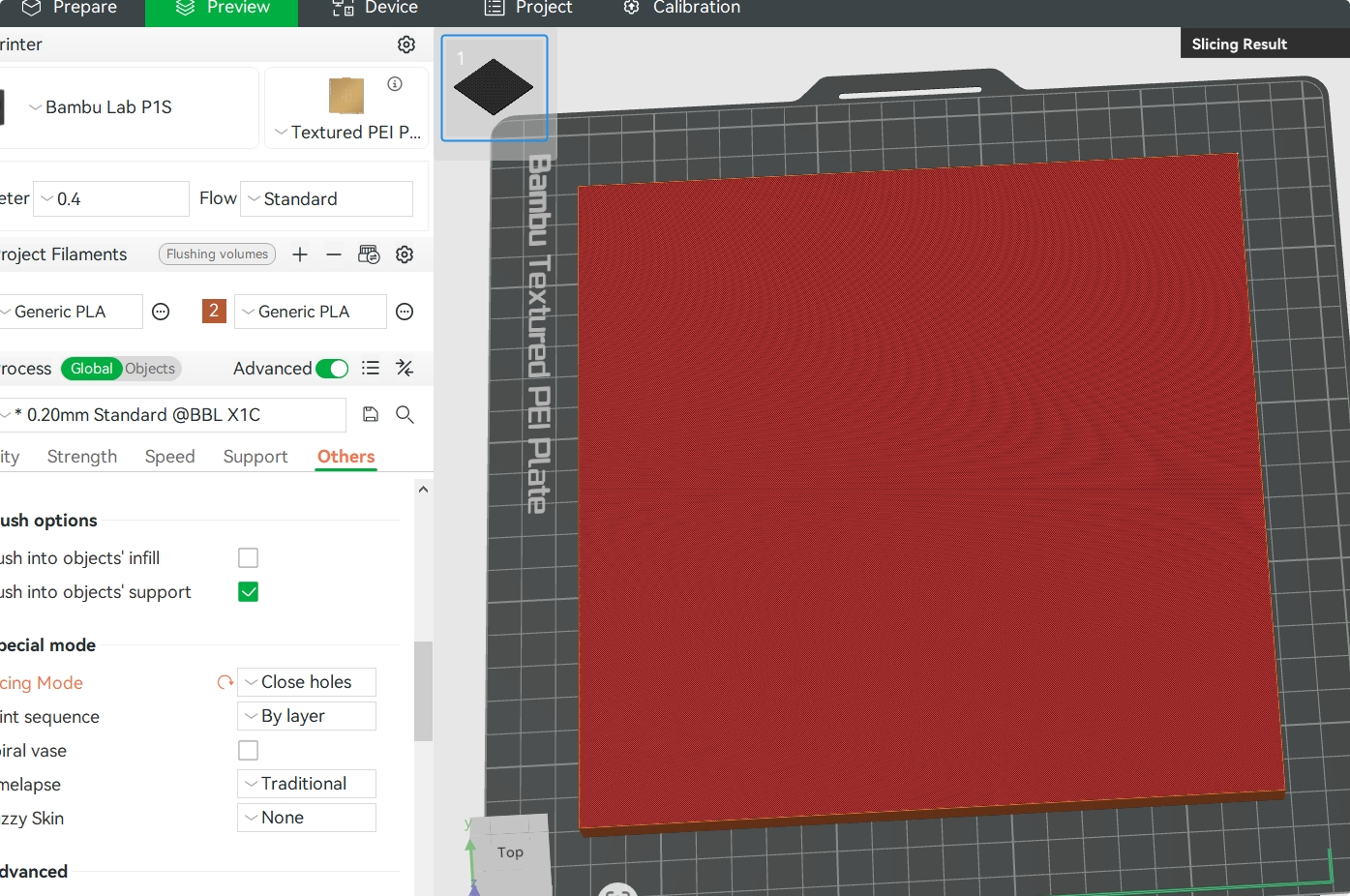
¶ Close Holes
This option seals open areas in a 3D model. It doesn't just close circular holes, but also fills any type of gap or open contour in the XY plane. For example, when used in the design below.

This is how it looks after applying “Close holes”. All the holes at the top were closed.
If the model has openings on the sides, they are interpreted as unclosed lines within a single layer and, therefore, are not identified as holes.

When using this option, exercise caution, as closing certain areas may unintentionally alter the model’s design or functionality.
¶ End Notes
We hope the detailed guide provided has been helpful and informative.
To ensure a safe and effective execution, if you have any concerns or questions about the process described in this article, we recommend submitting a technical ticket regarding your issue. Please include a picture or video illustrating the problem, as well as any additional information related to your inquiry.