¶ What is the Bambu Suite
Bambu Suite is a 2D graphics processing software from Bambu Lab, with custom features developed specifically for Bambu laser and cutting suites. It includes project-based processes, systematically optimized slicing algorithms, and an easy-to-use graphical interface, which is expected to bring you a smooth experience.
¶ System requirements
-Windows 10 system and above versions;
- Intel ® Core 2 or AMD Athlon ® 64 processor; 2 GHz or faster processors;
-A system that supports OpenGL 2.0;
-Recommend 8GB RAM, at least 4GB -20 GB or more available hard disk space;
¶ Installation procedure
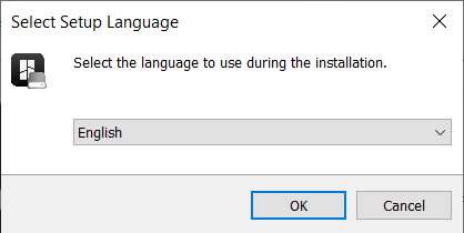
- Download the software installation package from the official website and double-click it to go to the software installation page. First, select the language you want to use.
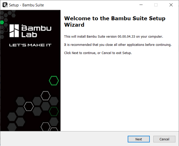
- Go to the installation welcome page and click Next.
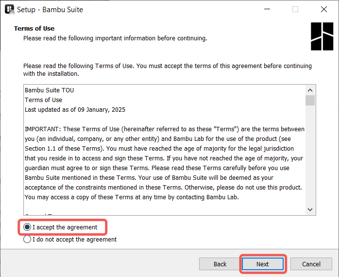
- Please read the terms of use, accept it, and enter the next step.
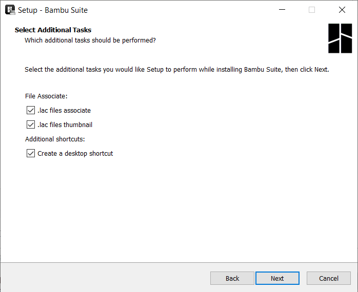
- Select additional tasks, and click "next" to install the software.
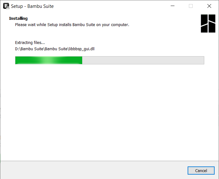
- After the installation, the software icon appears on the desktop, you can double-click to run it.
¶ Login and beginner tutorials
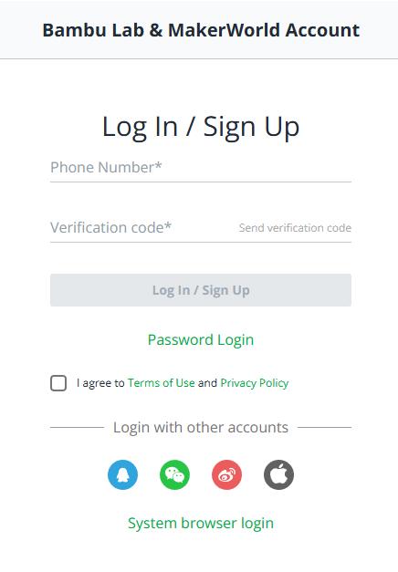
- The login page will pop up when the software is run for the first time. If there is no account, you need to create an account first (users in the Chinese Mainland need to log in with their mobile phone number as an account, while users outside the Chinese Mainland need to log in with their email address), or you can log in with a third-party account or system browser. To log in, you need to first agree to the software user agreement and privacy terms. You can click on it to view the detailed content.
- After logging in, enter the main interface of the software, and a beginner's tutorial will pop up. You can click "Next" to view each page and familiarize yourself with the overall layout and operation process of the software.
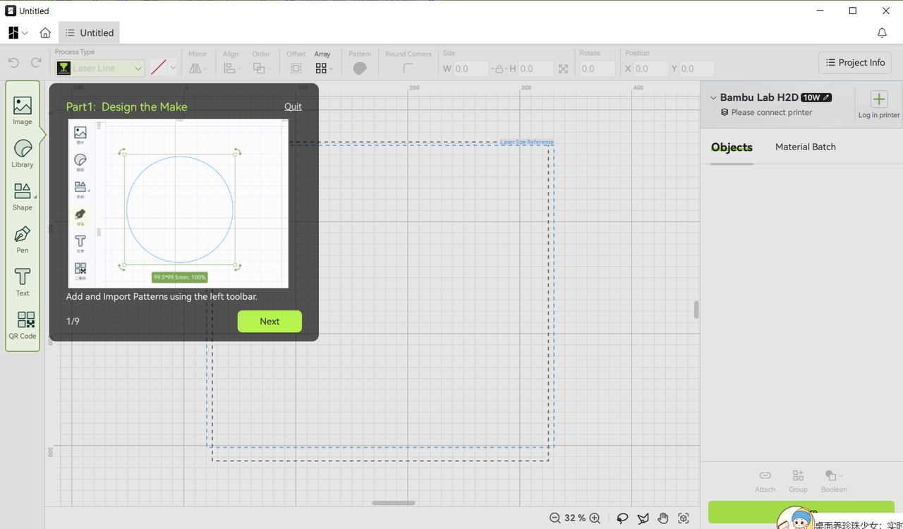
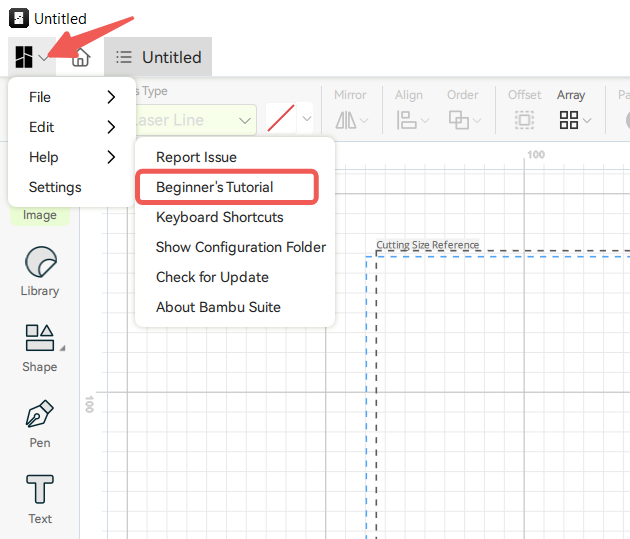
You can also temporarily exit the tutorial, and check again at any time in Help ->Beginner's Tutorial.
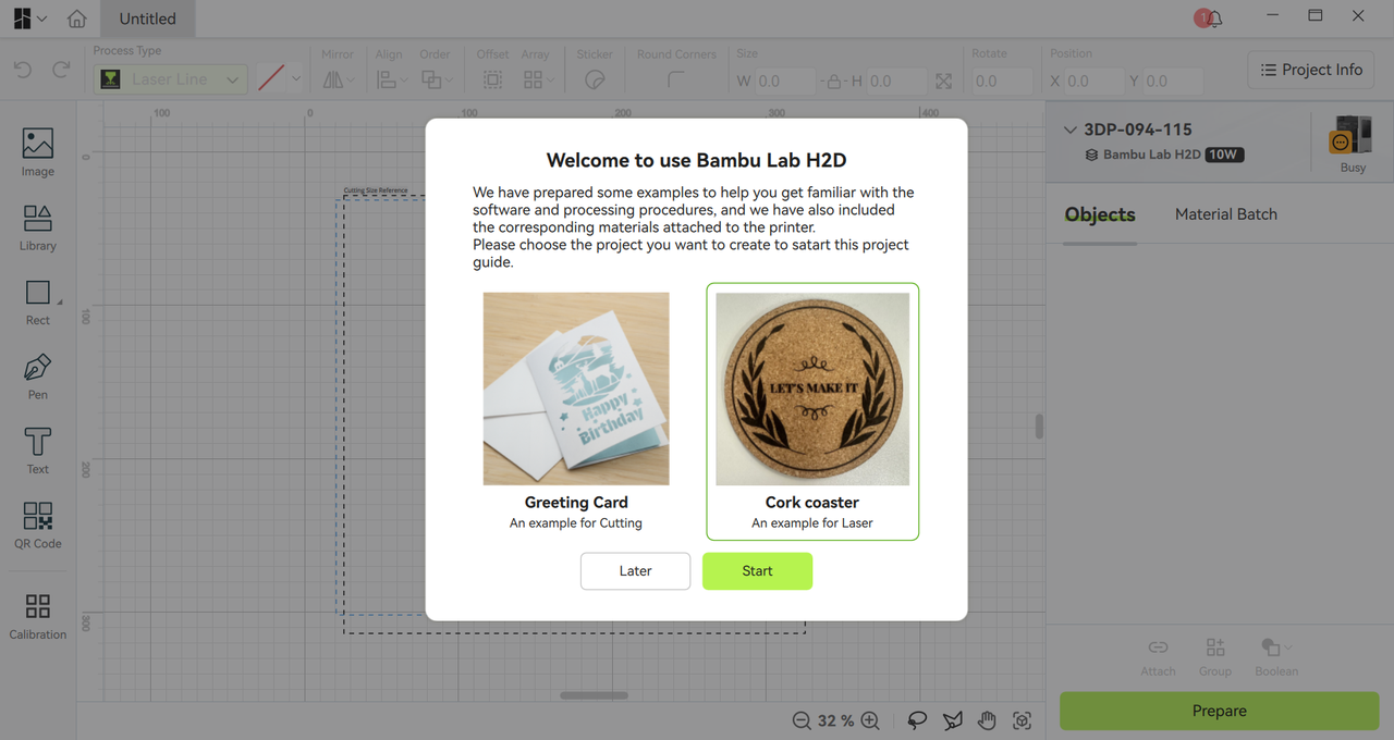
- In addition to the tutorial, when you bind and connect the machine for the first time, the software will automatically pop up the guide for novice production cases, and guide the user to make their first 2D work project step by step. You just need to follow the prompts and flashes of the software, click the relevant position, and you can use the machine to make your first work. Taking the BambuLab H2D model as an example, after the software is connected to the printer for the first time, it will automatically pop up the coaster case made by laser and the greeting card case made by the blade cutting to guide the user to complete the production process.
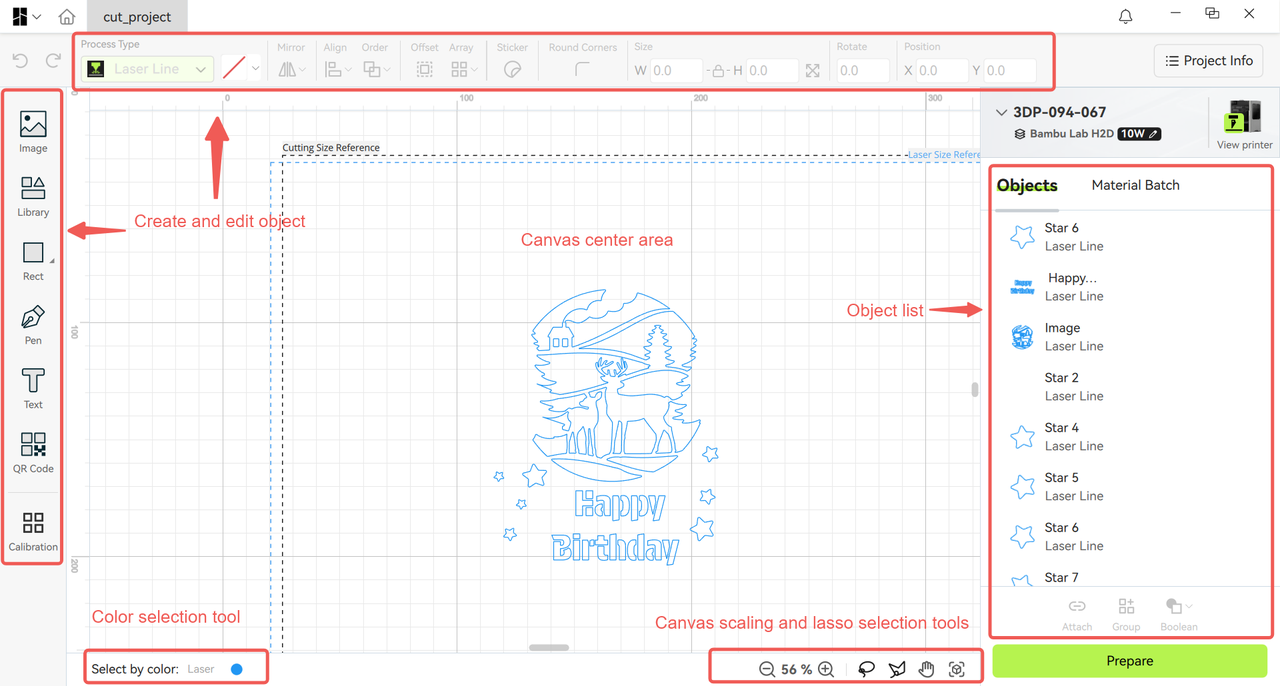
¶ Design interface
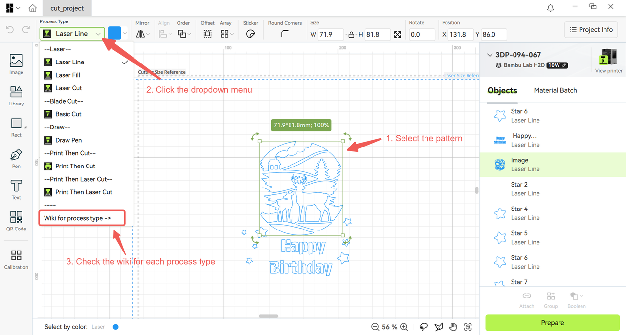
The software's overall design interface is a huge canvas with grids as the background, on which you can edit, design, and view the project's overall effect. In addition, different processing techniques can be added to different patterns, such as laser line engraving, laser filling engraving, laser line cutting, drawing pen, basic cutting, and so on. You can click on the wiki for process type in the drop-down list to view detailed introductions, applicable scenarios, and production effects for them.
The design page provides rich pattern creation and editing tools, including image import tools, shape tools (rectangles, circles, and arcs, etc.), pen tools, text tools, QR code generation tools, etc. Editing tools include setting the coordinate position and angle of patterns, setting rounded corners, setting the size and mirror of patterns, etc. The sticker tool is used to attach sticker border attributes to patterns, making it convenient for users to create cartoon stickers.
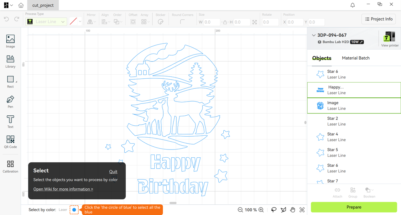
The upper right corner of the design interface is the entrance for machine connection and viewing, which facilitates users to bind and connect machines. The lower right middle side is a list of all pattern objects for the entire project, as well as commonly used object Groups and Boolean tools. You can further click on the material group label to set different processing materials for different patterns. At the bottom of the design interface are color selection tools, canvas scaling, and lasso selection tools, which facilitate users to adjust the size of the canvas and select the desired pattern objects in the canvas.
¶ Prepare interface
Click the "Prepare" button in the bottom right corner of the design interface to enter the preparation interface. In the preparation interface, users can preview the processing space and area of the machines that they can use during production. Therefore, complex projects are often divided into multiple plates for production. The overall layout of the prepared page is shown below.
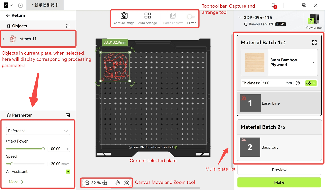
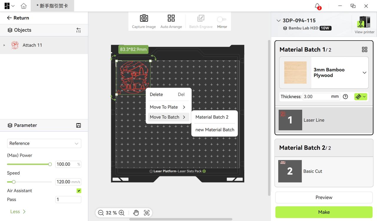
After entering the preparation interface, the software will automatically divide and arrange the plate according to the processing type of the pattern and the binding and grouping state, combined with the size of the production plate. You can click on the list of plates (material batch) on the right to view the patterns within each plate and specify what materials to use for each material batch. If you need to adjust the splits, you can select the pattern you want to manipulate and right-click, and the menu items to "move to the plates" and "move to the groups" will appear on the screen.
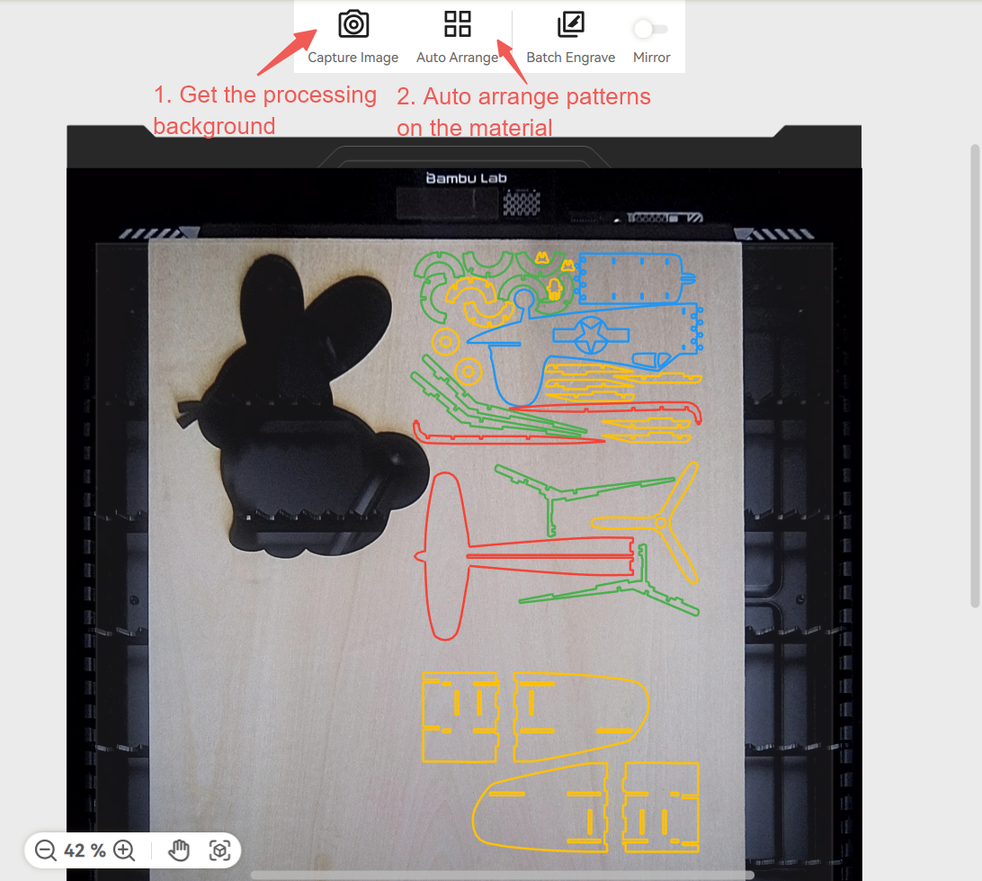
When you need to start processing, first click the "Capture Image" button to obtain the background image of the material and check if the pattern is placed in the appropriate position of the material. If the pattern is not placed on the material, you can manually select the pattern for movement, or simply click the "auto arrange" button. The software will automatically recognize the outline and position of the material, and adjust the pattern within the range of the material.
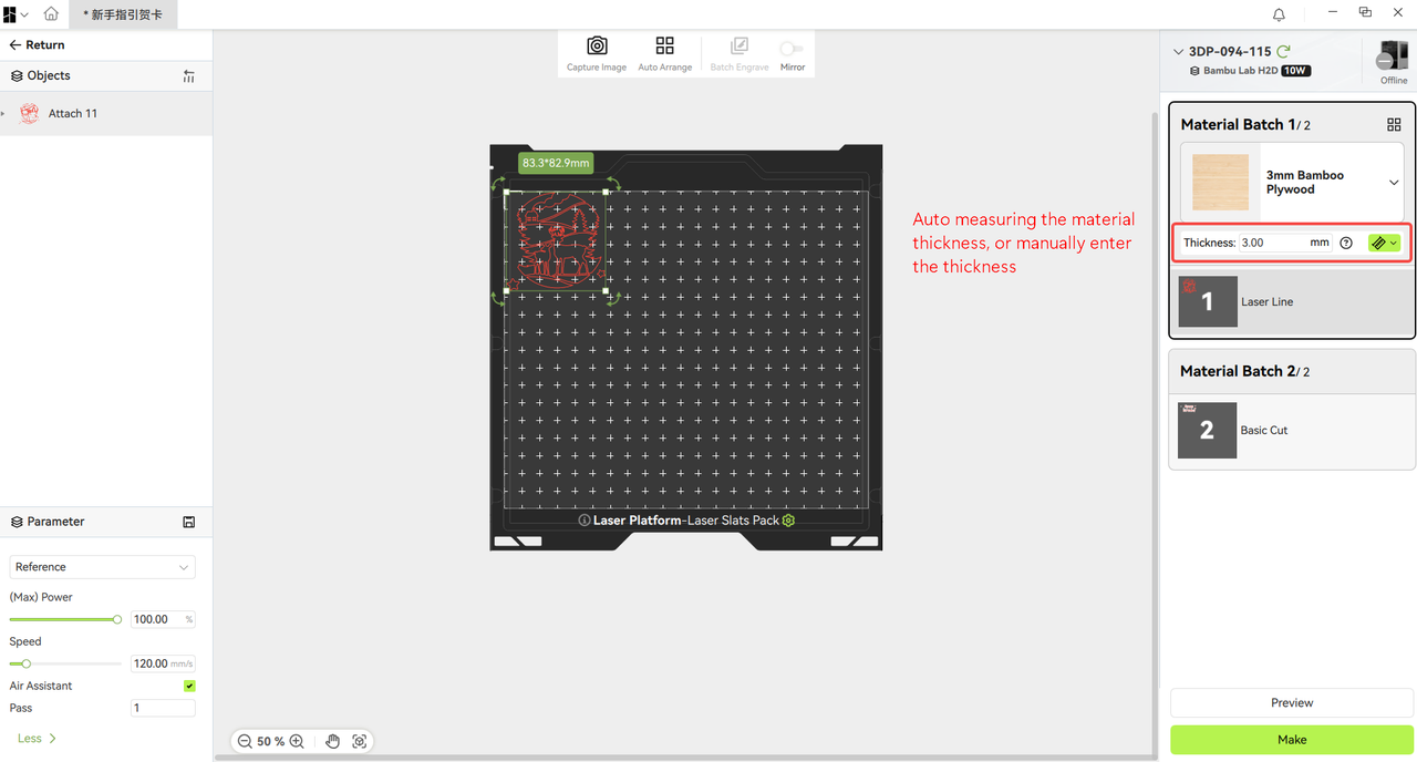
Laser processing needs to focus the laser so that the laser cursor appears in a minimum state on the surface of the material to ensure the processing quality. The software provides the height-measuring function option that will trigger the machine to measure the thickness of the material. For scenarios where the material reflects light and cannot be measured, you can manually measure the thickness of the material and fill in the parameter box.
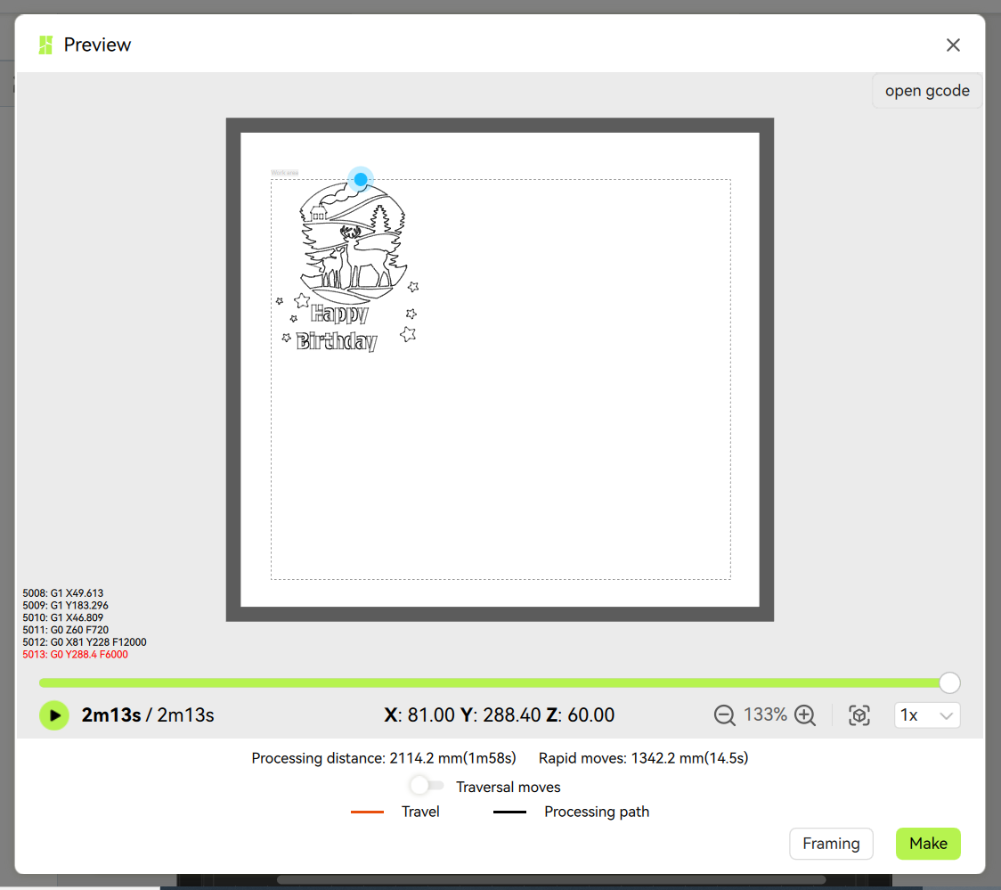
After completing the pattern placement, you can start processing. Before processing, you can click the preview button in the lower right corner to view the processing path and duration. The preview interface is shown below. You can drag and drop the progress bar below or click the play button in the bottom left corner to view the simulation process of the processing path.
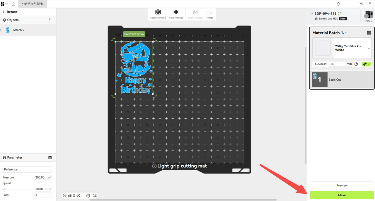
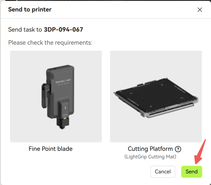
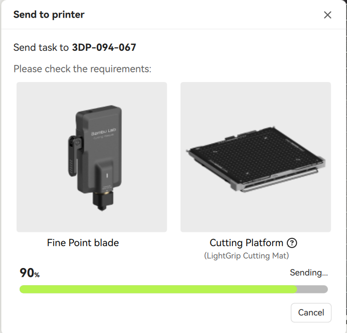
Then you can click the "Make" button, and the software will pop up to prompt the user what machining tool and platform type to use. After confirming that the relevant tool and platform are installed, you can click "Send" to start processing.
¶ Production process monitoring interface
After the task is successfully sent, the software automatically jumps to the production process monitoring page. First, it will prompt the user to go to the machine before the operation, to ensure that the relevant materials, tool head, and platform are ready.
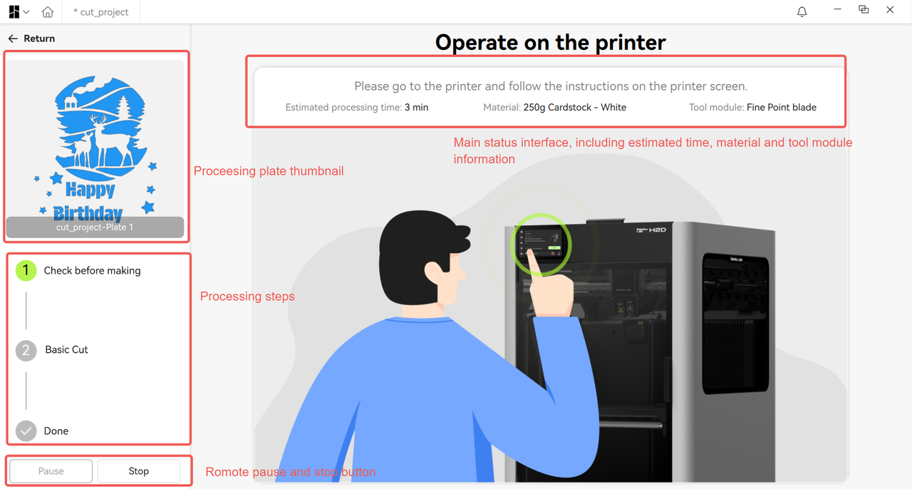
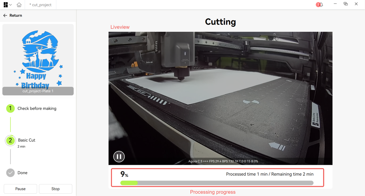
When you walk up to the machine and confirm that everything is ready, click the button according to the on-screen prompts to start the processing. After starting the processing, if the machine is equipped with a live camera, you can remotely view the monitoring image of the camera through software and wait for the processing to be completed. When there is an abnormality in the processing task or when you do not want to continue, you can use the button in the bottom right corner of the interface to pause or abort the production task.
Process each plate according to the above steps until the entire project is completed.
¶ End Notes
We hope the detailed guide provided has been helpful and informative.
If this guide does not solve your problem, please submit a technical ticket, we will answer your questions and provide assistance.
If you have any suggestions or feedback on this Wiki, please leave a message in the comment area. Thank you for your support and attention!