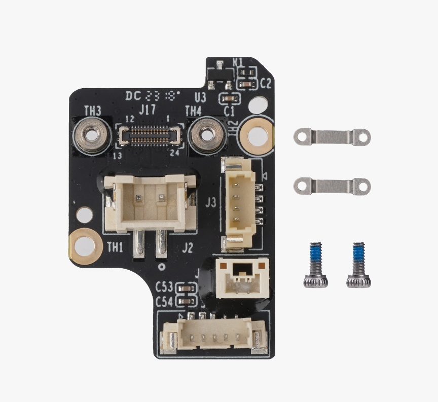
¶ Extruder Connection Board - X1 series
¶ When to use?
- The connectors and components were damaged
- Issues were found through a printer LOG analysis
¶ Tools and materials needed
- H1.5 hex key
- Bambu Lab Extruder Connection Board
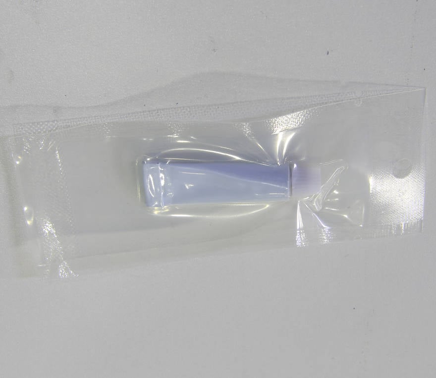
- Silicon glue
- Scapel or a sharp knife
¶ Safety Warning
IMPORTANT!
It's crucial to power off the printer before performing any maintenance work on the printer and its electronics, including tool head wires, because leaving the printer on while conducting such tasks can cause a short circuit, which can lead to additional electronic damage and safety hazards.
When you perform maintenane or troubleshooting on the printer, you may be required to disassemble some parts, including the hotend. This process can expose wires and electrical components that could potentially short circuit if they come into contact with each other or with other metal or electronic components while the printer is still on. This can damage the electronics of the printer and cause further damage.
Therefore, it's essential to switch off the printer and disconnect it from the power source before doing any maintenance work. This will prevent any short circuits or damage to the printer's electronics. By doing so, you can avoid potential damage to the printer's electronic components and ensure that the maintenance work is performed safely and effectively.
If you have any concerns or questions about following this guide, open a new ticket in our Support Page and we will do our best to respond promptly and provide you with the assistance you need.
¶ Disassembly Steps
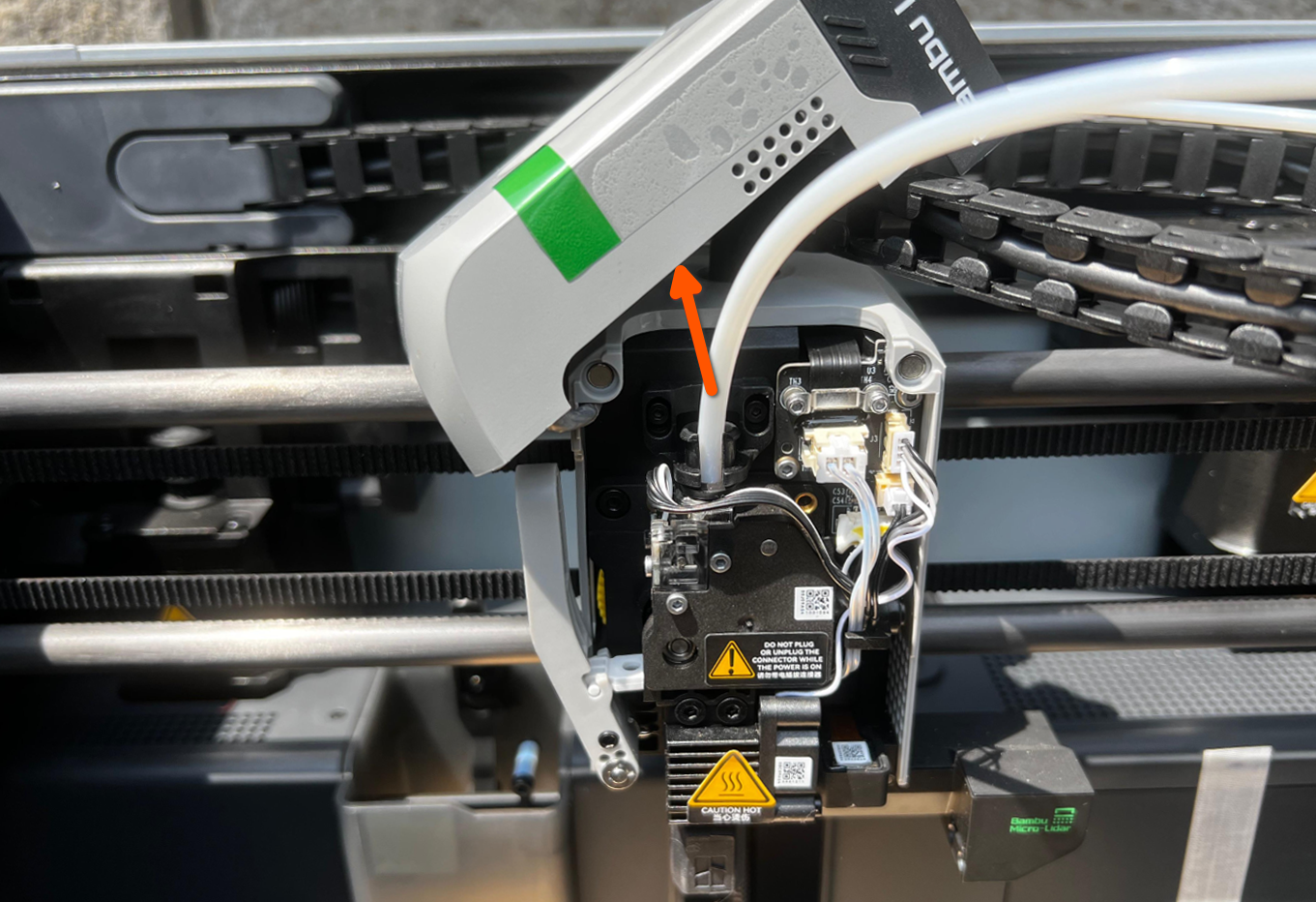
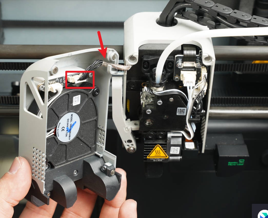
¶ Step 1 - Remove the front housing
Open the front housing and rest it on the carbon rod, as shown below. Do this gently to avoid damaging the attached cables.
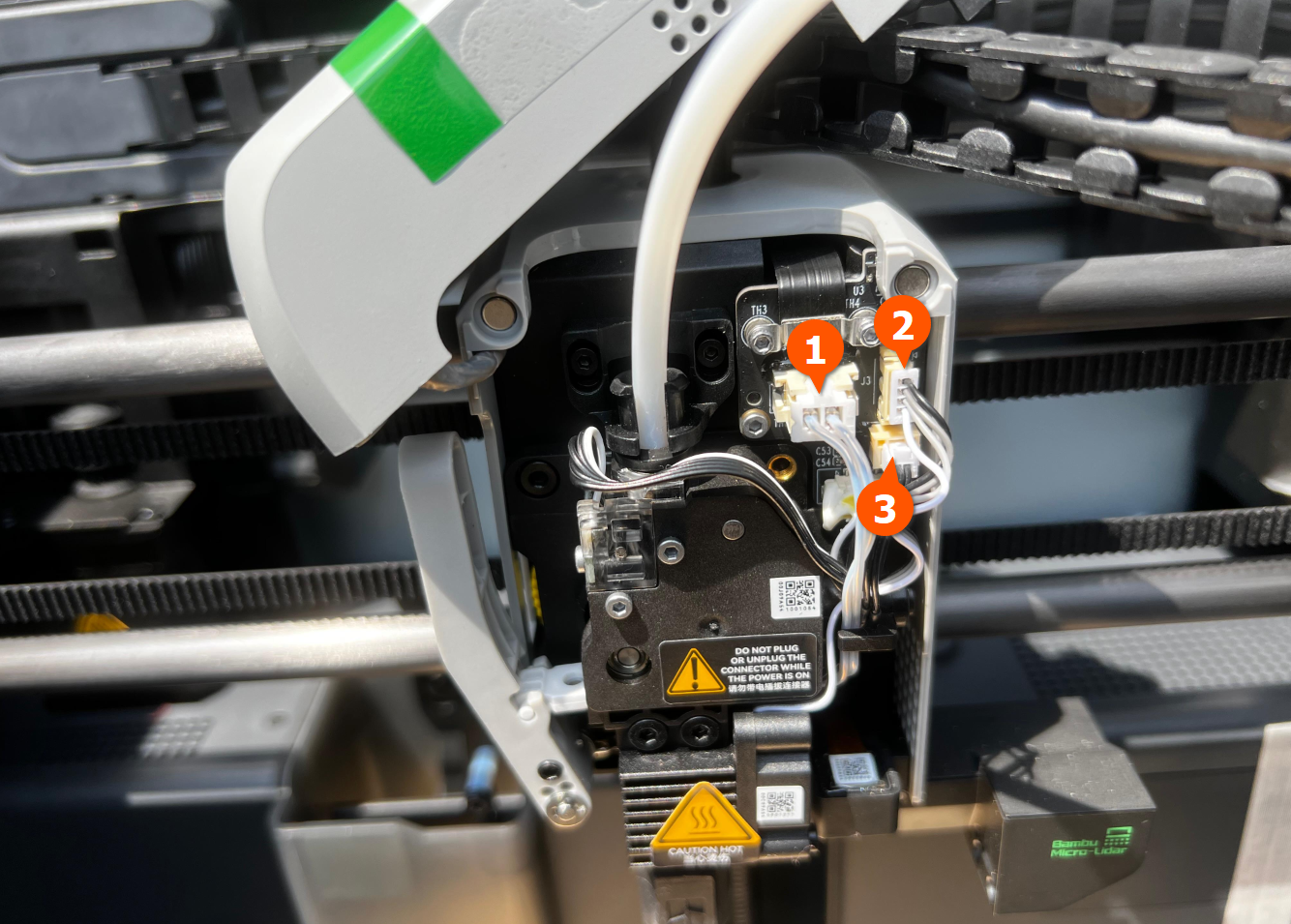
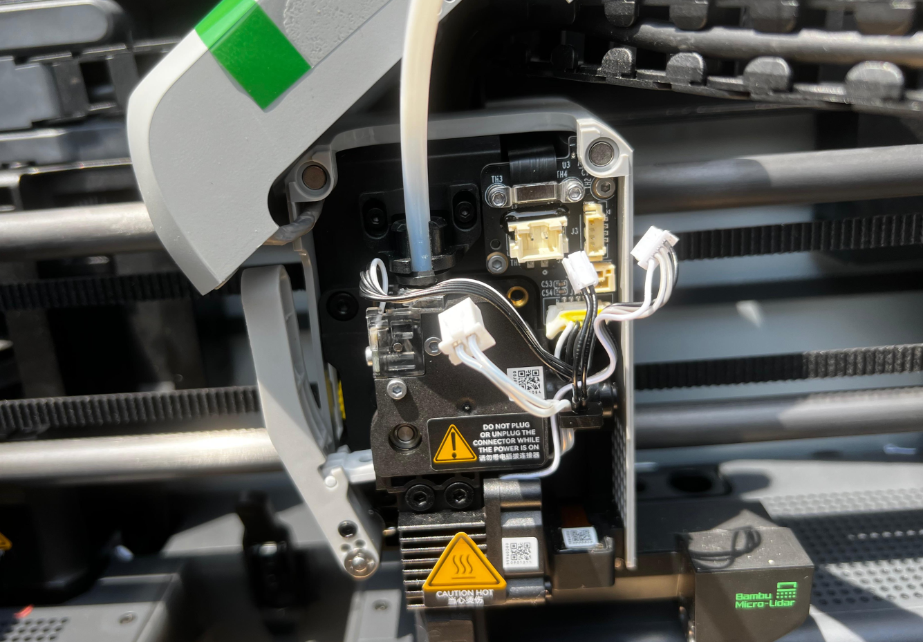
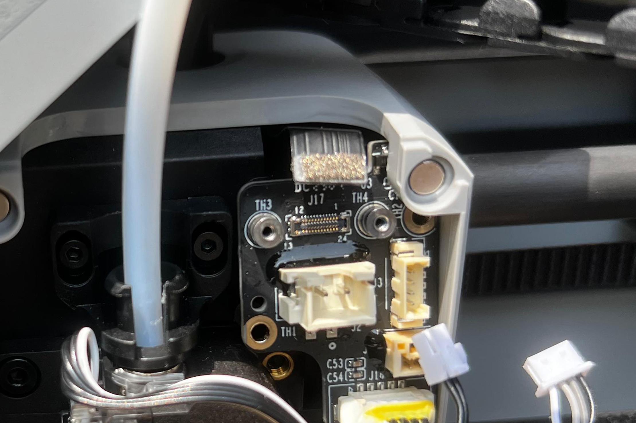
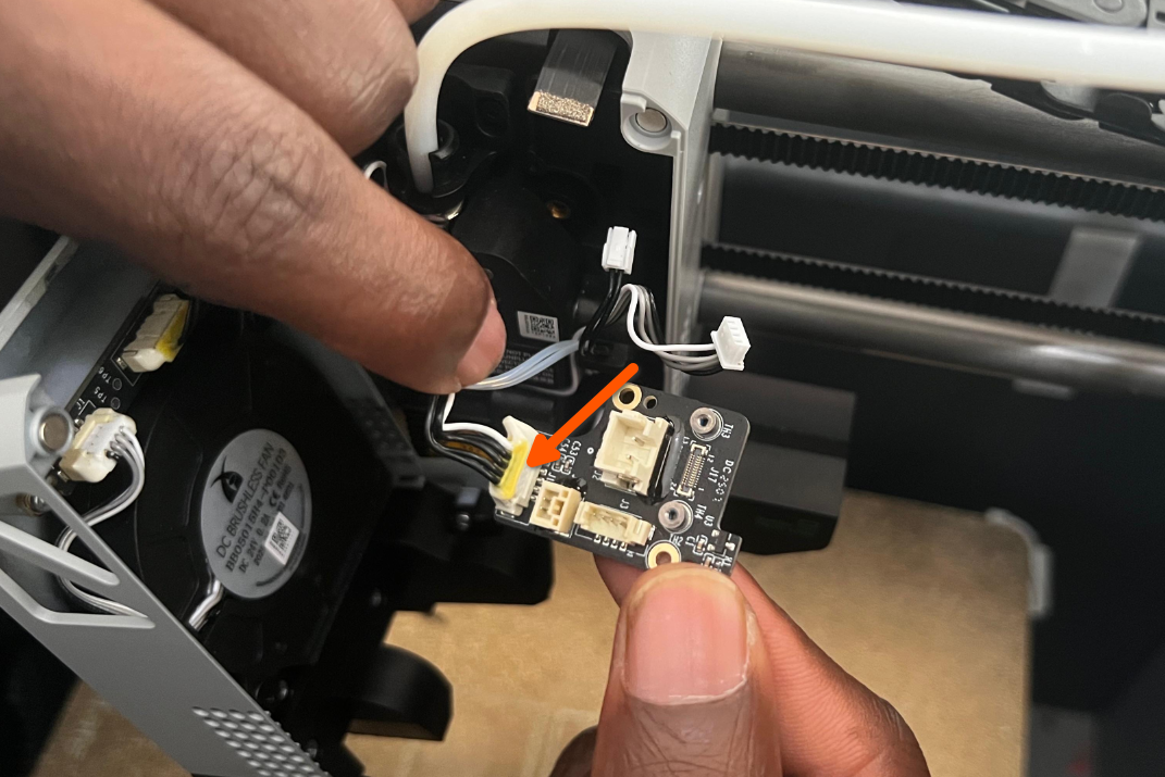
¶ Step 2 - Disconnect the cables from the Extruder Interface board
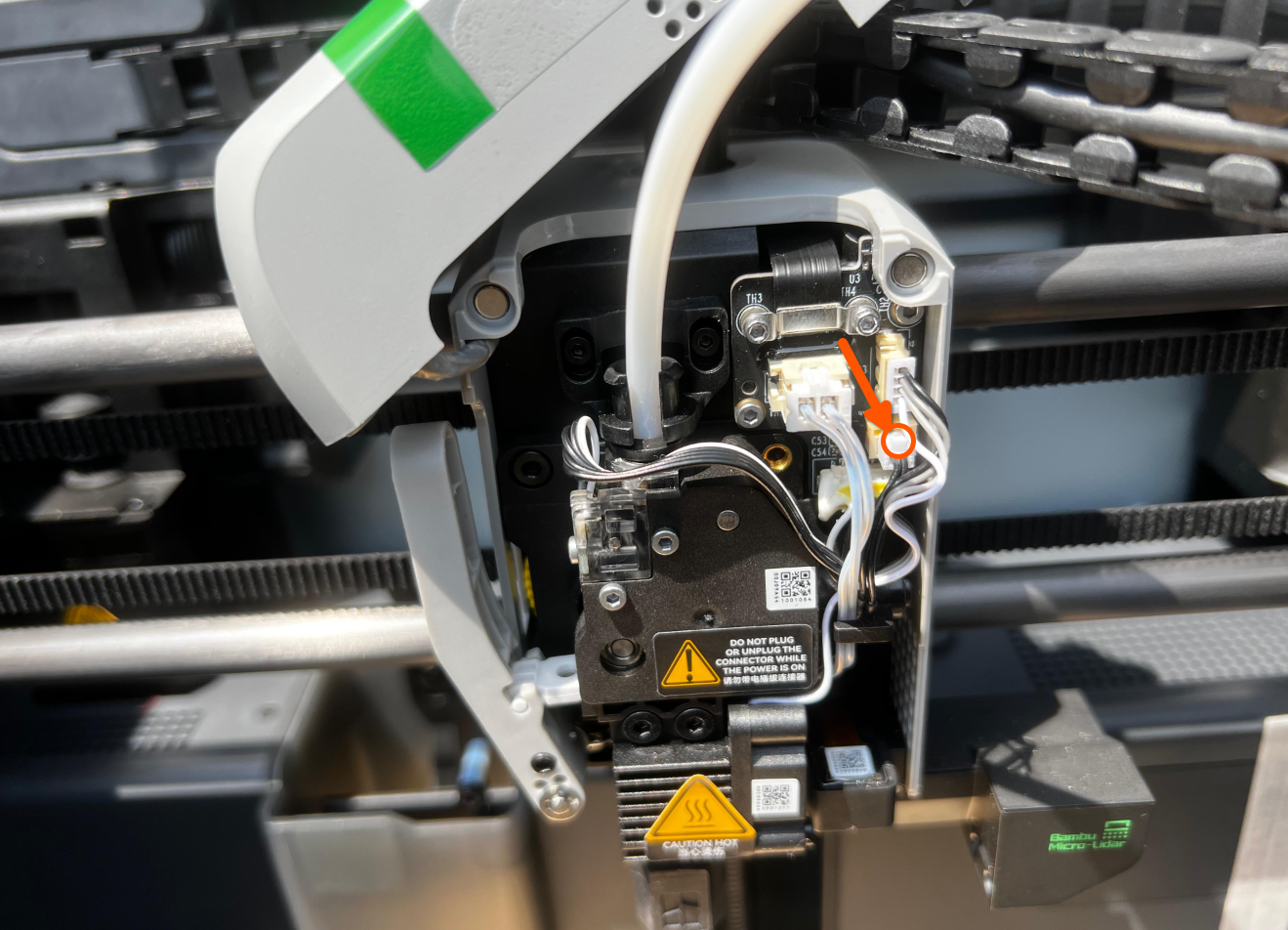
Disconnect the the three hotend cables that are connected to the interface board.
 |
 |
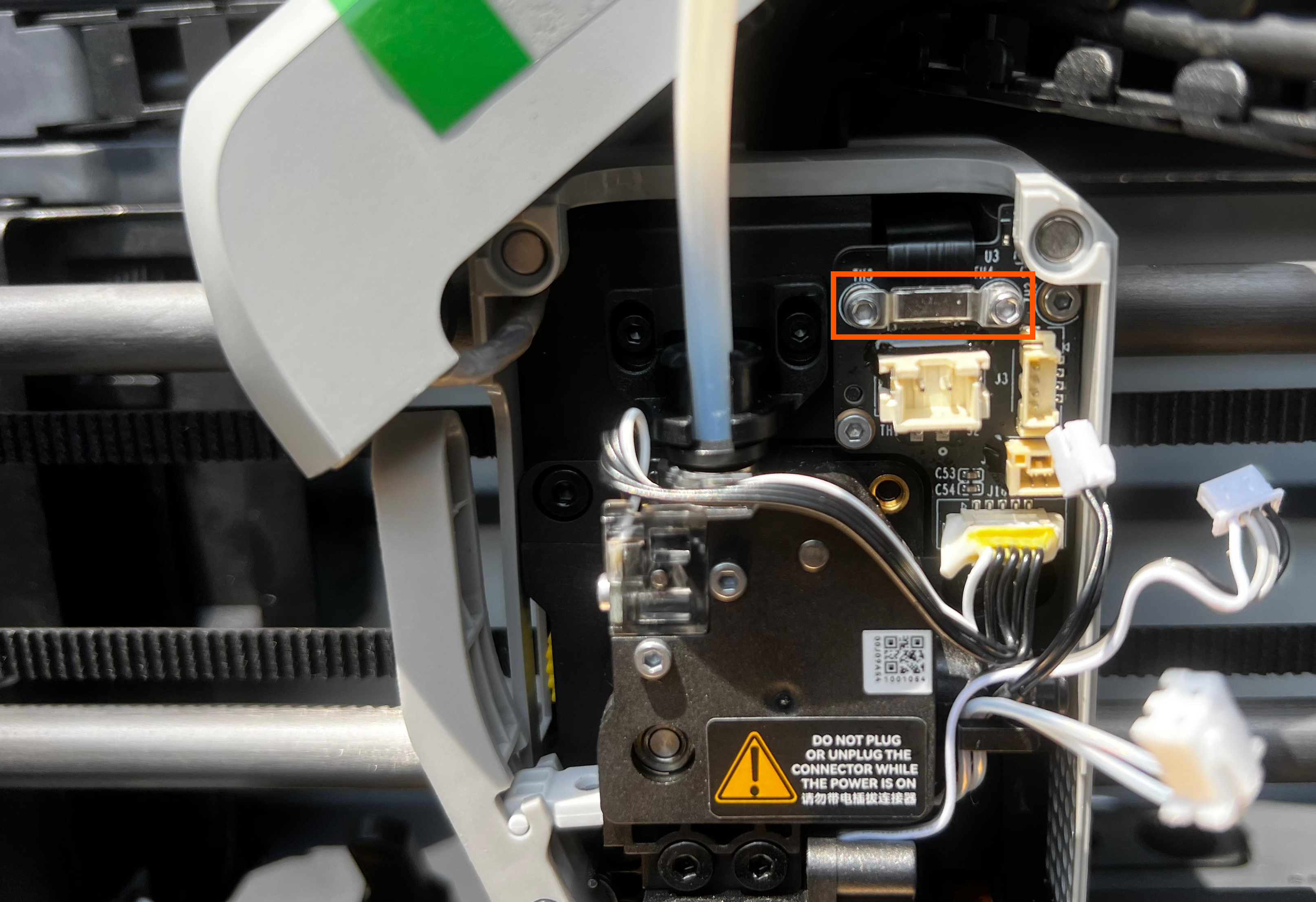
Warning: For cables 1 and 2, remove them by holding and pulling the connector, not the wires. For cable 3, the plug has a latch. Push the latch to release it instead of pulling on the wires or plug, as this may cause the entire PCB connector to detach. The latch location is shown below.
Do not remove the extruder cable at the bottom yet. Remove it only after taking out the extruder interface board, as it is tightly secured with silicone glue. This will help avoid damaging other parts in the process.
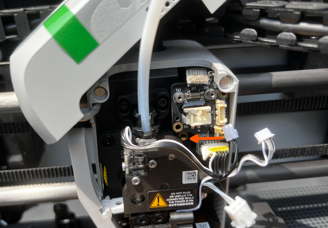
¶ Step 3 - Remove the screws and FPC cable
Remove the four screws using the H1.5 hex key. Remember to keep the bracket in the first two screws.
Note: The screws used are smaller in size.Keep them safe so that they don't get lost.
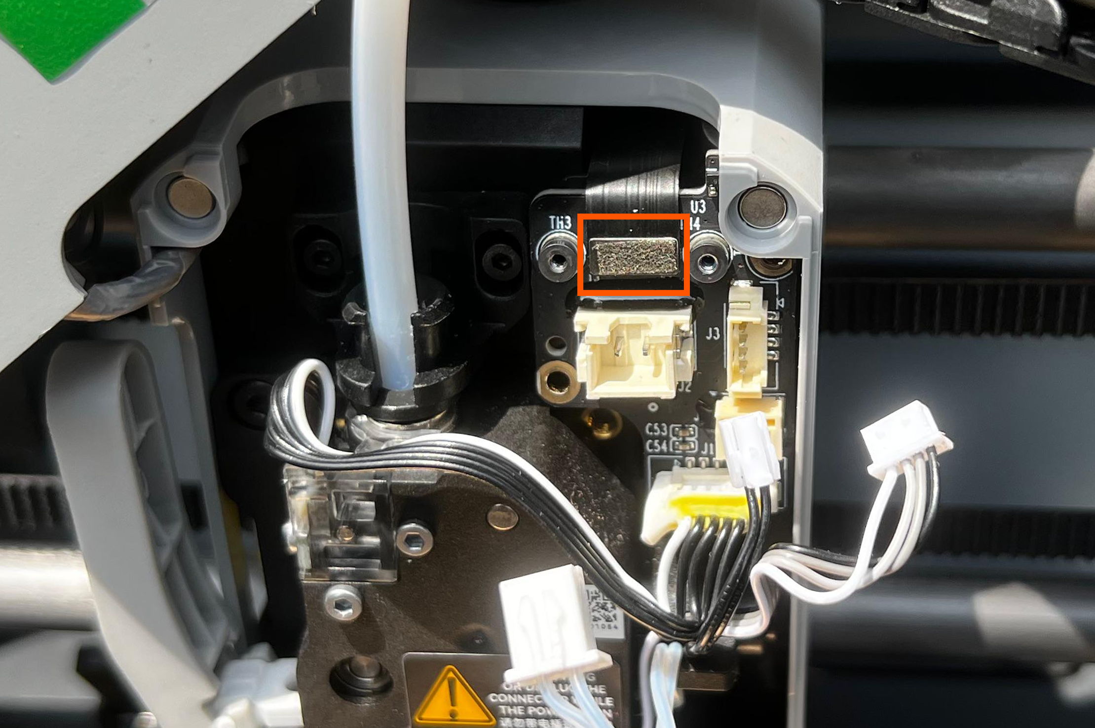
Then, disconnect the FPC from the interface board.
 |
 |
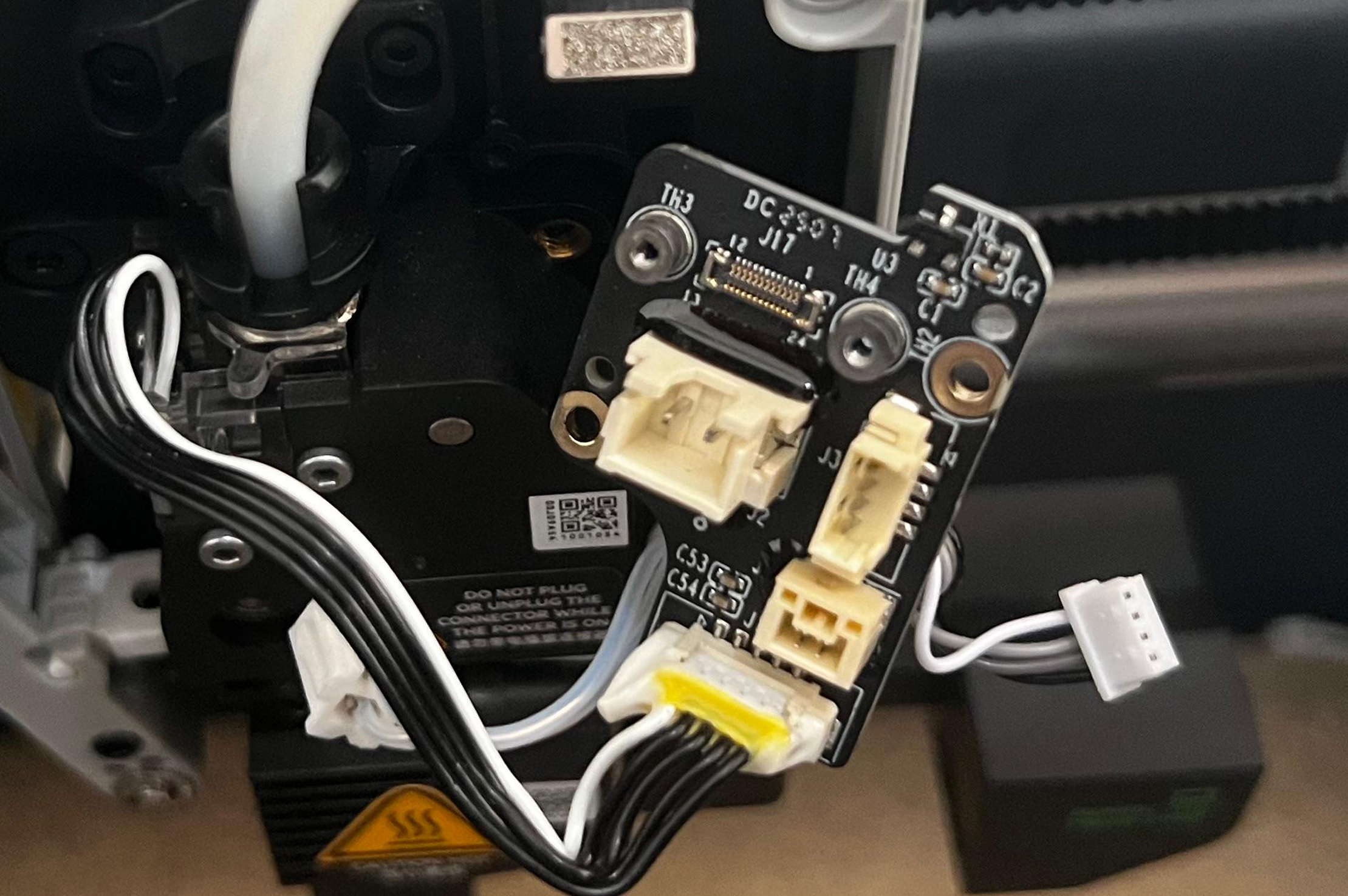
¶ Step 4 - Remove the interface board
Hold the extruder interface board, tilt it slightly to the left, and remove it gently.
 |
 |
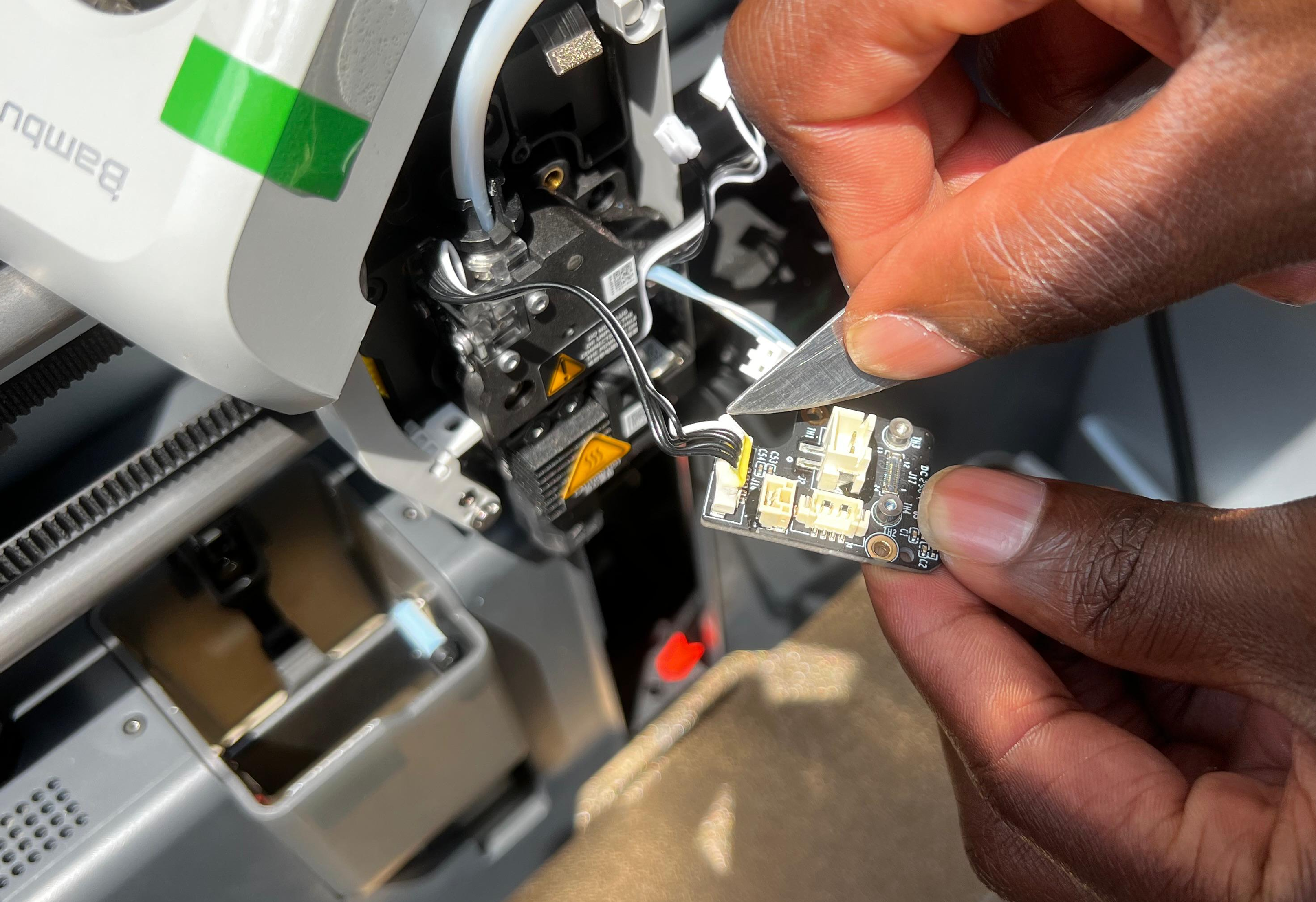
¶ Step 5 - Remove the extruder cable
Remove the silion glue attaching the extruder cable to the interface board using a scapel or a sharp knife. The silicone glue is used for holding the connector in place during shipping and re-gluing is optional. Be careful when doing this to avoid cutting the connector or the wire.
Then, disconnect the extruder cable.
We have now successfully disassembled the extruder interface board.
¶ Assembly Steps
¶ Step 1 - Install the interface board
Connect the extruder cable. Then, install the interface board onto the tool head, and ensure it's correctly in its place then connect the FPC to the connectors of the interface board, and reinforce them with crimping brackets and screws.
Next, tighten the two remaining screws, and then connect the three hotend cables.
 |
 |
|
Note: Do not overtighten the screws, as this may damage the brackets or board.
¶ Step 2 - Install the front housing
Close the front housing, and ensure the attached front cable is securely in place and properly inserted.
¶ Verify functionality
-
Visually inspect the interface board and the cables and verify that everything is firmly in place.
-
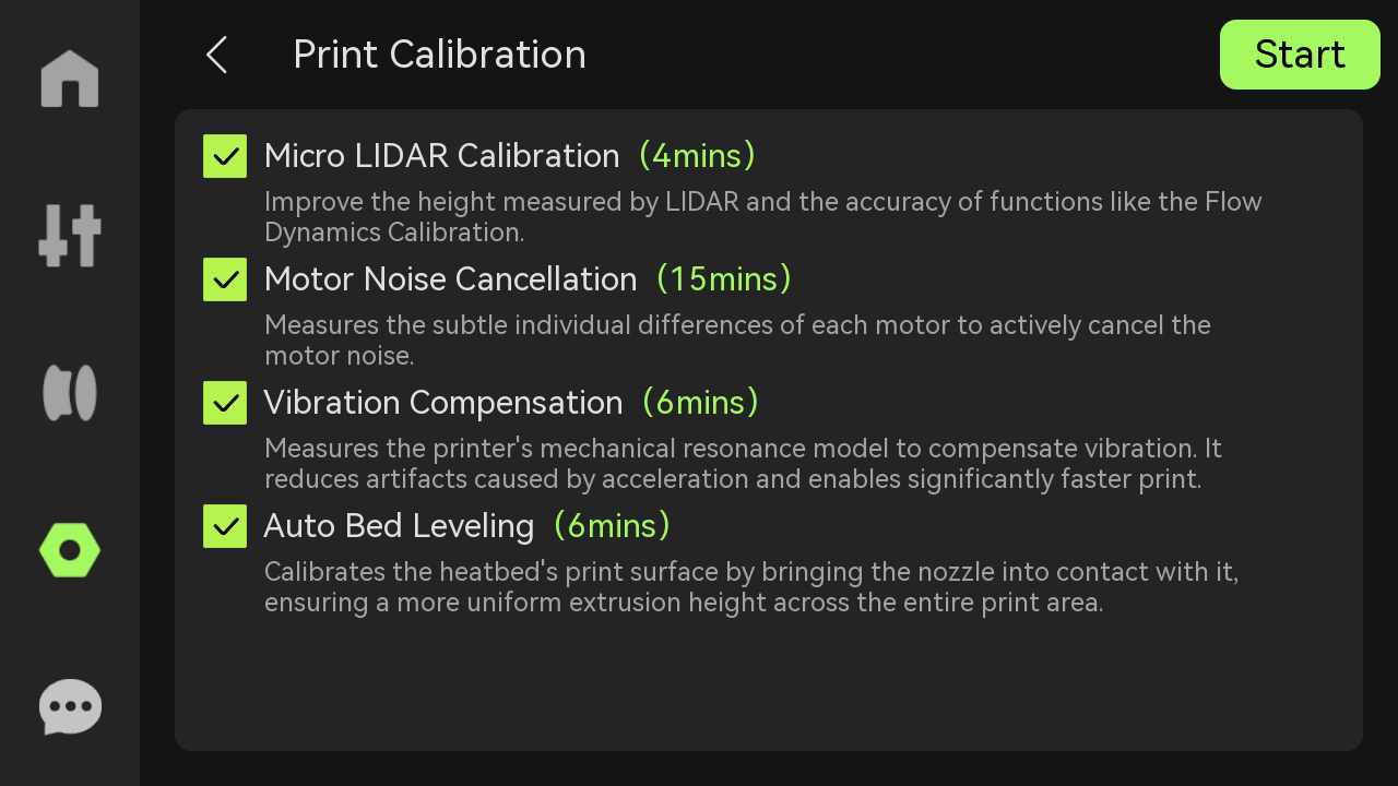
Power on the printer and initiate the device calibration process. Check to see if it passes the calibration process.
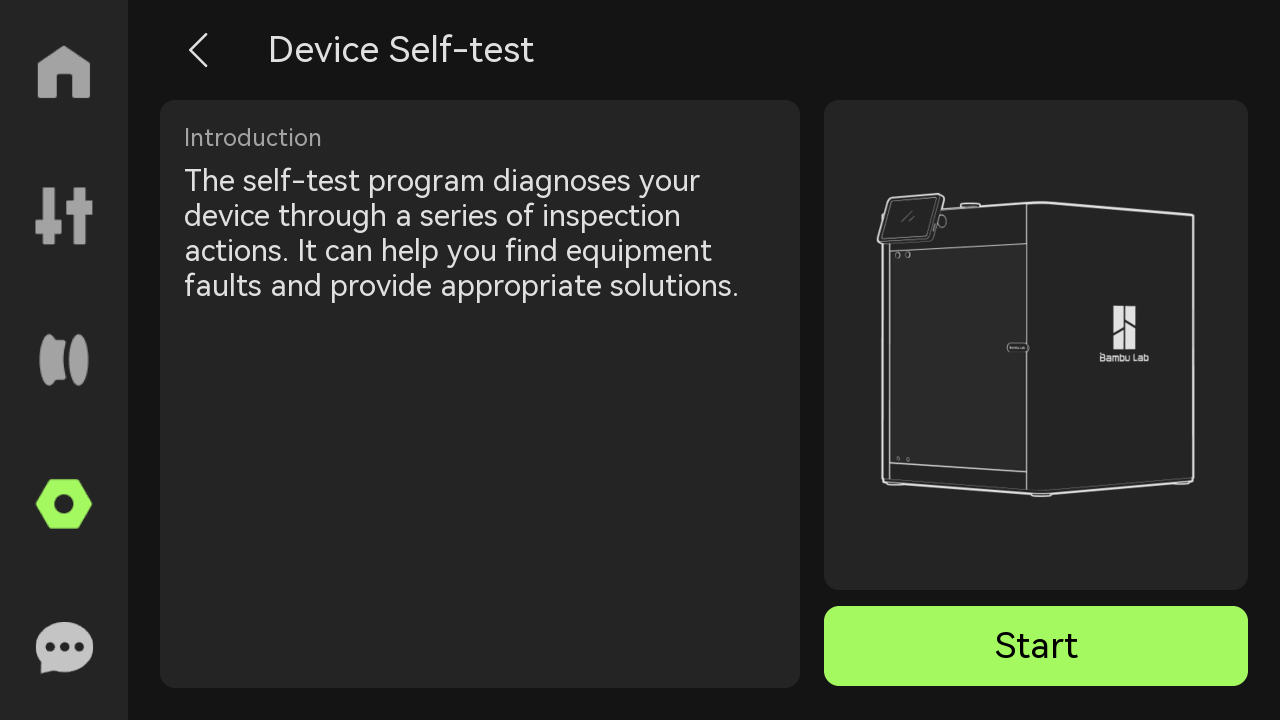
- Run a Device self-test operation as shown below and if no errors occur, the replacement was successful.
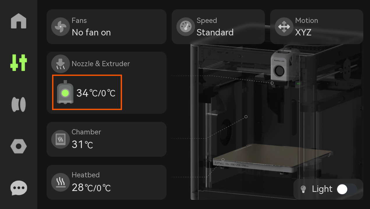
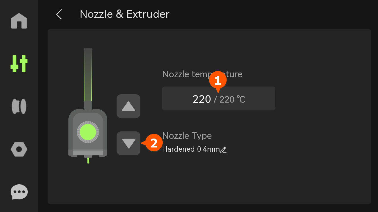
- Check to see if the nozzle and extruder temperature is greater than 0c.
Then, increase it to an appropriate value like 220° for PLA and extrude some filament. A smooth filament flow should ooze out the nozzle without any disturbance.
 |
 |
¶ Potential issues and solutions
- If the extruder motor fails to move: Check if the extruder cable is securely connected to the interface board.
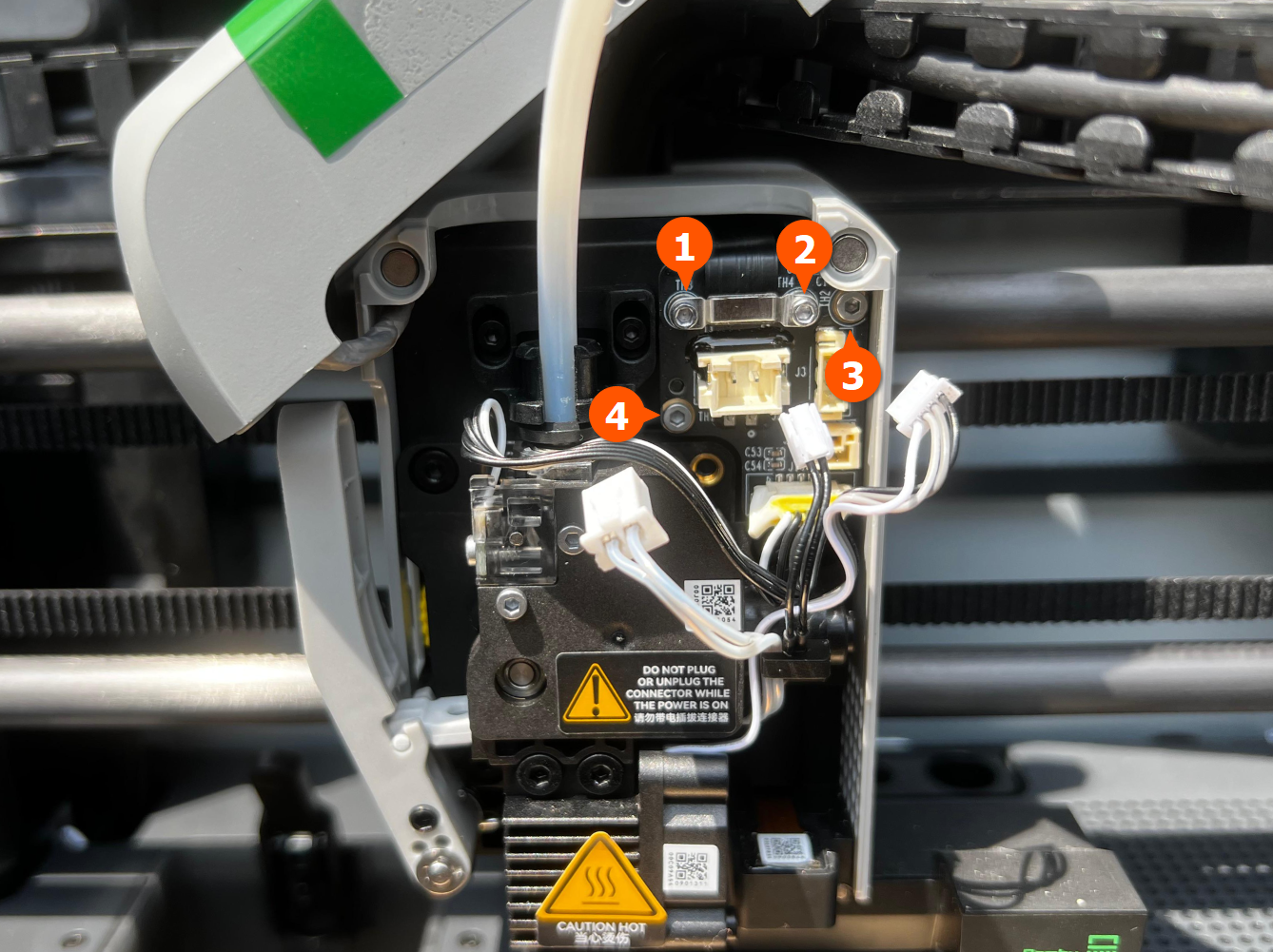
- If the hotend temperature is not detected, verify that the connector marked with 1 in Step 2 of the disassembly section is securely connected to the interface board.
- If the hotend is not heating, verify that the connector marked with 3 in Step 2 of the disassembly section is securely connected to the interface board.
- If the printer displays an HMS error: Confirm the FPC cable is inserted in the correct direction and fully seated.
¶ End Notes
We hope the detailed guide provided has been helpful and informative.
If this guide does not solve your problem, please submit a technical ticket, we will answer your questions and provide assistance.
If you have any suggestions or feedback on this Wiki, please leave a message in the comment area. Thank you for your support and attention!