¶ What is this AC board
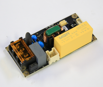
This AC board is a circuit board that provides AC power for the X1 series V2 version heatbed.
¶ When to use
When the heatbed does not heat up, or the AC board is burnt.
¶ Tools and materials needed
- New AC board
- H1.5 & H2.0 allen key
- Phillips screwdriver.
¶ Safety warning and Machine state before starting operation
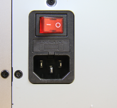
Turn the power OFF and disconnect the power cord from the power socket.
¶ Operation guide
¶ Step 1 - Disconnect the power cord
Turn the power OFF and disconnect the power cord from the power socket.
¶ Step 2 - (Disassembly) Remove screws
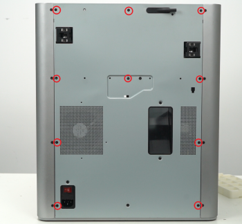
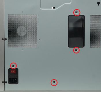
NOTE: There are a lot of screws involved in this procedure. Please label them and group them in separate sections as to avoid issues.
Remove the 10 screws and 4 screws from the rear cover shown in the picture. There are 2 types of screws, so keep them separate and remember which ones go where.
 |
 |
¶ Step 3 - Remove the rear cover
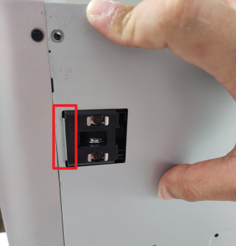
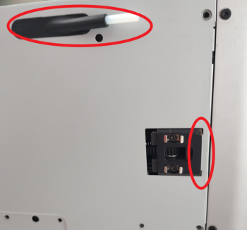
Remove the rear cover by unlocking the left side belt tension port first, and then the right side one to avoid getting stuck.
 |
 |
¶ Step 4 - Removing the excess chute
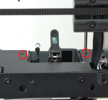
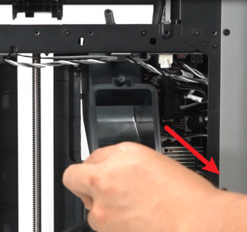
Undo the screws located at each side of the excess chute. once done, take out the excess chute. Some printers have three screws to secure the excess chute, while others only have two; please refer to your unique situation.
Note: For some versions, the heat bed cables are fixed to the bottom of the excess chute with a buckle, do not use too much force when taking off the excess chute.
Two screws case:
 |
 |
Three screws case:
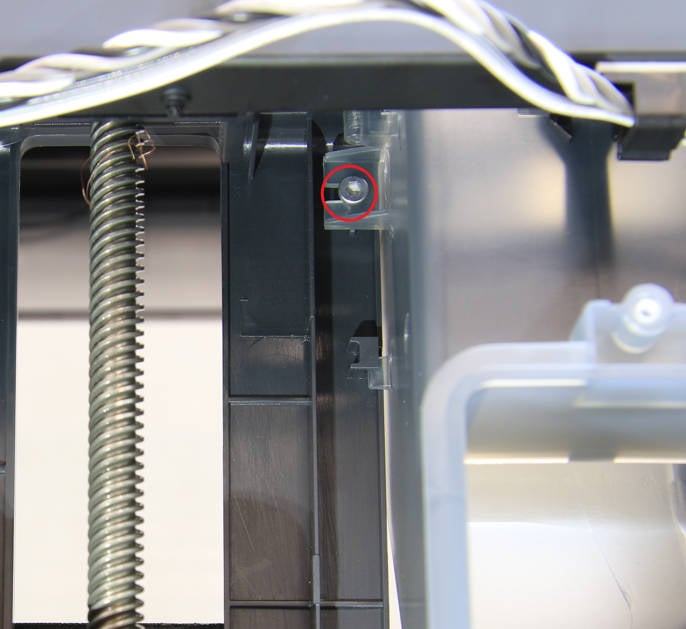 |
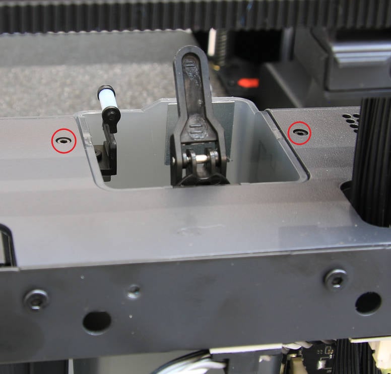 |
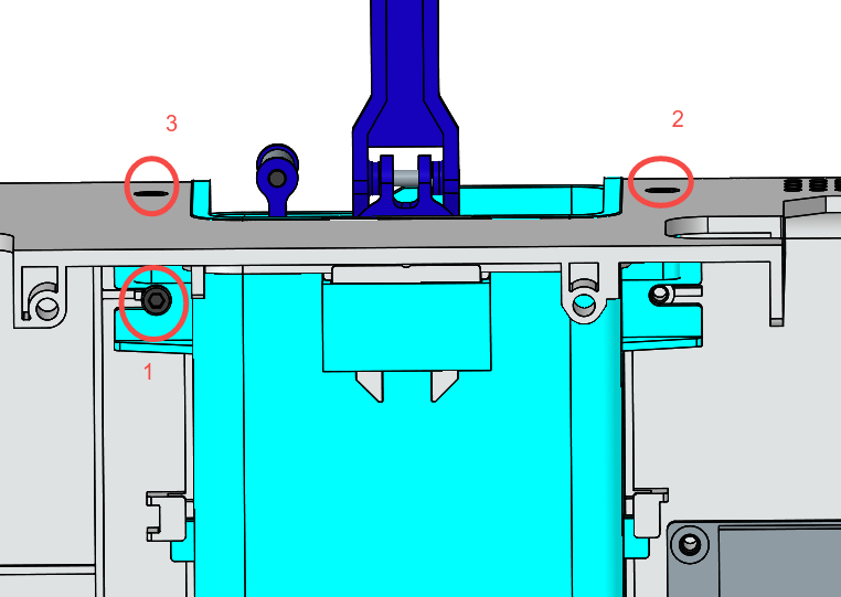 |
¶ Step 5 - Remove the power module protect cover
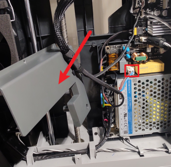
Remove the 6 screws shown, move the power module protect cover to the side and disconnect the power cable of the heatbed.
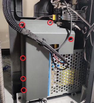 |
 |
¶ Step 6 - Disconnect cables
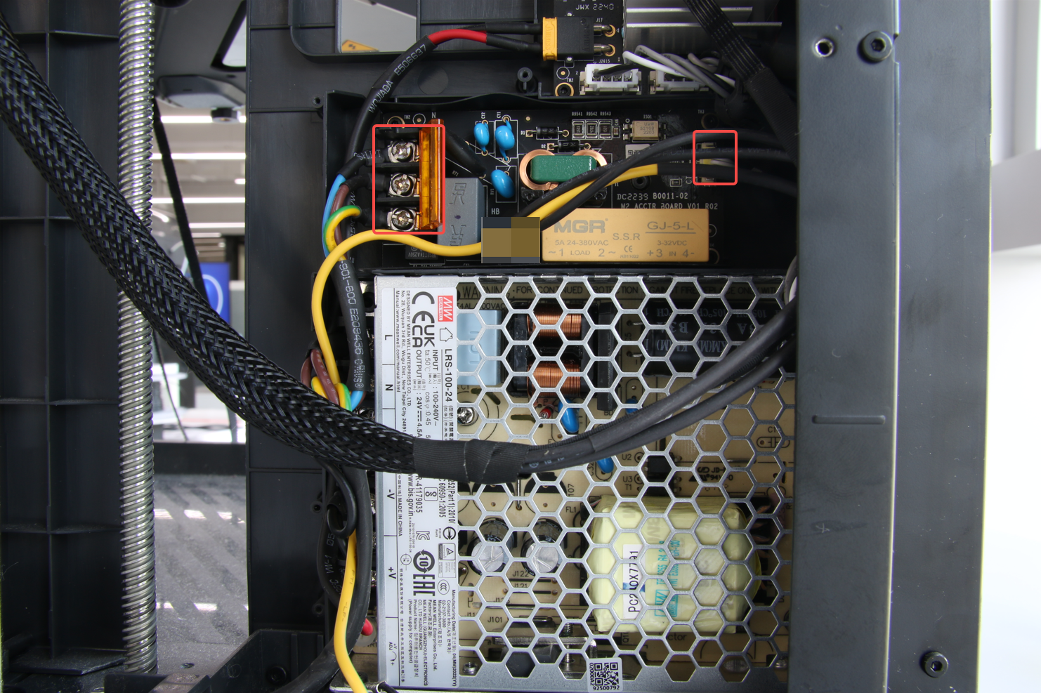
Open the power interface cover, loosen (but don't remove) the 3 screws, remove the 3 power cables and disconnect the MC-AC connect cable.
¶ Step 7 - Remove the AC board
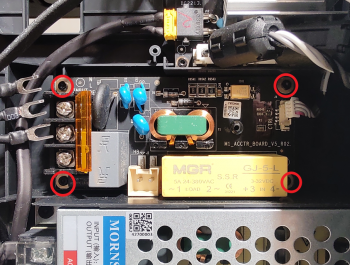
Remove the 4 screws as shown, and then remove the AC board.
 |
 |
¶ Step 8 - (Assembly) Install the AC board
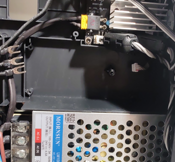
Reverse the procedure and install the new AC board to the inner shield using the 4 AC board screws.
 |
 |
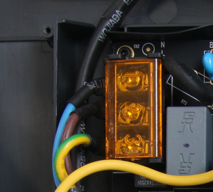
¶ Step 9 - Connect cables
Connect the AC-MC connect cable, connect the 3 power cables and tighten the screws, close the interface cover.
|
 |
 |
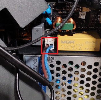
¶ Step 10 - Connect the heatbed power cable
Connect the power cable of the heatbed.
¶ Step 11 - Install the power module protect cover
Install the power module protect cover, and secure it with the 6 screws.

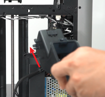
¶ Step 12 - Install the excess chute
Install the excess chute, pay attention to the buckles on both sides, and use the 2 screws to secure it.
 |
 |
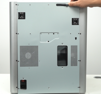
¶ Step 13 - Install the rear cover
Pass the PTFE tube through the tube bracket, install first the right side belt tension port, and then the left side to install rear cover.
 |
 |
¶ Step 14 - Install the 10+4 screws
Install the 10 + 4 screws (see picture).
 |
 |
¶ How to verify completion/success
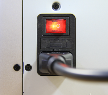
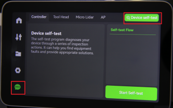
Connect the power cord and turn on the power, then navigate the LCD screen to start a self-test. If no errors occur, the replacement is complete. Success!!
 |
 |
Otherwise, check the connections, and try it again. If still you have errors, contact the service team for solution advice.